1
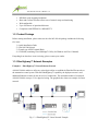
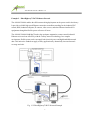
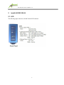
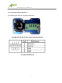
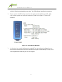
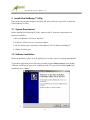
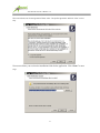
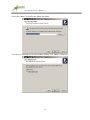
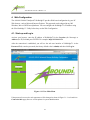
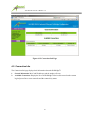
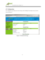
AIA1803-200-04 User’s Manual v1.0
AIA1803
AIA1803-200200-04
EtherHighway™ Industrial Ethernet
NetBridge™
User’s Manual
Version 1.0
1
AIA1803-200-04 User’s Manual v1.0
IMPORTANT SAFETY INFORMATION
1.
2.
3.
4.
5.
Please read all instructions before installing and operating AIA1803-200-04 and keep all
instructions for later reference.
Please follow all performance and safety requirements for each installation, including any
applicable laws, regulations, codes and standards.
Do follow all the warnings and instructions marked on the product.
AIA1803-200-04 is NOT field serviceable and should not be opened under any
circumstance.
Aboundi is not responsible or liable for indirect or consequential damage resulting from the
use or application of this product.
2
AIA1803-200-04 User’s Manual v1.0
Copyright © 2011 by Aboundi Inc. All rights reserved.
No part of this documentation may be reproduced in any form or by any means or used to make any
derivative work (such as translation, transformation, or adaptation) without written permission from
the copyright owner.
All the other trademarks and registered trademarks are the property of their respective owners.
Statement of Conditions
The content described in this manual may be improved or changed at any time and it is subject to be
changed without notice.
Manufacturer assumes no responsibility for errors contained herein or for direct, indirect, special,
incidental or consequential damages with the furnishing, performance, or use of this manual or
equipment supplied with it, even if manufacturer of its suppliers have been advised of the
possibility of such damages.
Electronic Emission Notices
This device complies with Part 15 of the FCC Rules. Operation is subject to the following two
conditions:
(1) This device may not cause harmful interference.
(2) This device will accept any interference received, including interference that may cause
undesired operation.
Audience
The information in this manual is composed for technicians, engineers and network administrators
who are installing and maintaining a control system that includes the AIA1803-200-04 NetBridges.
You should have a basic knowledge of:
(1) Microsoft Windows OS
(2) Ethernet Networks Installation and Maintenance
Support
(1) Phone: 1-603-889-8188
(2) Fax: 1-603-889-8181
(3) Email: [email protected]
(4) Web: http://www.aboundi.com/Support/Technical_Support.html
Please contact your local Aboundi representative if you need an on-site support.
3
AIA1803-200-04 User’s Manual v1.0
Table of Content
1.
Introduction ................................................................................................... 5
1.1.
1.2.
Features .....................................................................................................................5
Product Package.........................................................................................................6
1.3.
EtherHighway™ Network Examples..........................................................................6
2.
Install AIA1803-200-04 ................................................................................. 8
2.1.
2.2.
2.3.
LED ...........................................................................................................................8
Communication Interfaces .........................................................................................9
Din Rail Mounting ................................................................................................... 10
2.4.
2.5.
2.6.
2.7.
Make a secured Ethernet cable (optional) ................................................................. 11
Connect the Ethernet RJ45 Ports .............................................................................. 12
Connect the Signal and Power Wires ........................................................................ 12
Inspect The Connectivity ......................................................................................... 14
3.
Install Ultra NetBridge™ Utility.................................................................. 16
3.1.
3.2.
4.
System Requirement ................................................................................................ 16
Software Installation ................................................................................................ 16
Web Configuration....................................................................................... 24
4.1.
4.2.
4.3.
4.3.1.
4.3.2.
4.4.
4.5.
4.6.
4.7.
5.
Start-up and Log in .................................................................................................. 24
Connection Info ....................................................................................................... 25
Configuration ........................................................................................................... 26
Security Page ........................................................................................................... 27
Network Page .......................................................................................................... 28
Change Password ..................................................................................................... 29
Firmware Upgrade ................................................................................................... 30
Factory Reset ........................................................................................................... 31
Reboot ..................................................................................................................... 32
Default Settings ........................................................................................... 32
4
AIA1803-200-04 User’s Manual v1.0
1. Introduction
The traditional Ethernet network cabling for the industrial automation I/O device network requires
the deployment of new CAT5 wiring in addition to the legacy I/O process and control infrastructure.
This addition of another paralleled wiring infrastructure at the I/O network level increases the Total
Cost of Ownership (TCO) and ongoing operational maintenance expenditures. Aboundi’s patent
pending AIA1803-200 series of EtherHighway™ Industrial Ethernet NetBridge™ allows a
Plug-and-Play simplicity utilizing the existing robust floor DC power electrical wiring as means of
providing the network service. The Aboundi solution dramatically reduces the Total Cost of
Operation (TCO) with its product line installation flexibility.
The robust AIA1803-200 NetBridge™ enclosure is designed to withstand the harsh industrial
operating environments.
1.1. Features
EtherHighway™ capability layer the Ethernet communication over the power wires and
thus eliminates need for a separate communication wiring
Compatible with all Ethernet ready I/O modules
Simple Plug-and-Play installation
168-bit Tri-DES encryption for secure data transmission
Robust housing
Supports Industrial operating temperature
5
AIA1803-200-04 User’s Manual v1.0
DIN-Rail ready mounting installation
Ident-and-Connect™ feature allows ease of network setup and monitoring
Web configurable
Up to 300 meters of operational distance
Compliance with IEEE802.3u 100BASE-TX
1.2. Product Package
Before starting installation, please make sure the AIA1803-200-04 package includes the following
five items:
1)
2)
3)
4)
Quick Installation Guide
AIA1803-200-04 unit
Female type 4-PIN Terminal Block
CD-ROM (containing Ultra NetBridge™ Utility for Windows and User’s Manual).
If anything from the above items is missing, please contact your vendor.
1.3. EtherHighway™ Network Examples
Example 1 – EtherHighway™ Linear Ethernet Network
AIA1803-200-04 enables to utilize any twisted pair cables to establish the EtherNet/IP networks on
the automation control system. With the EtherHighway™ capability, the deployment won’t need
additional Ethernet switches for the device level connections. The maximum number of connected
AIA1803-200-04 can up to 32 in a physical wiring. The graphic below shows an example of a linear
network.
Fig. 1.3.1 EtherHighway™ Linear Network Example
6
AIA1803-200-04 User’s Manual v1.0
Example 2 – EtherHighway™ RGV Ethernet Network
The AIA1803-200-04 enables the efficient networking deployment on the power track in the factory.
It provides a reliable high speed Ethernet connection to enable networking for the industrial PLC
control, HMI, industrial computer, IP cameras, video servers, and other Ethernet interfaced I/O
equipments through the flexible power rail across all areas.
The AIA1803-200-04 NetBridge™ makes the warehouse automation, remote control industrial
Ethernet easier and cost effectively with the TrolleyConnect™ technology. In a complex
environment, flexible power tracks can supply both electrical power and high bandwidth network
data. This innovative method can apply to many applications by dramatically increased network
coverage and scale.
Fig. 1.3.2 EtherHighway™ RGV Network Example
7
AIA1803-200-04 User’s Manual v1.0
2.
Install AIA1803-200-04
2.1. LED
The following figure shows the AIA1803-200-04 LED indicator.
8
AIA1803-200-04 User’s Manual v1.0
2.2. Communication Interfaces
The following figure shows the communication interfaces.
9
AIA1803-200-04 User’s Manual v1.0
2.3. Din Rail Mounting
Follow the steps below to mount AIA1803-200-04 on a DIN rail.
1.
Determine a proper DIN rail. This product’s grounded through the DIN rail to the chassis
ground. Please make sure the material of the DIN rail to mount is good conductor to avoid
improper or intermittent grounding.
2.
Holding the AIA1803-200-04 body and hook the latch over the DIN rail bottom.
3.
List the unit and push the unit to lock on the latch.
Figure 2.3.1 - AIA1801-200-04 on DIN Rail
10
AIA1803-200-04 User’s Manual v1.0
2.4. Make a secured Ethernet cable (optional)
Dismantle the secured Ethernet RJ45 connector cover. You can find it in the package.
Inset the Ethernet cable through the cover parts then make a RJ-45 connector.
Tighten the parts and cable then screw on the cover parts.
11
AIA1803-200-04 User’s Manual v1.0
2.5. Connect the Ethernet RJ45 Ports
Follow the steps below to connect the Ethernet RJ45 port on the AIA1803-200-04 unit.
1.
Locate the Ethernet RJ45 port on the bottom of the unit. Connect one end of an Ethernet cable
with RJ45 jack to the Ethernet port on the unit.
Figure 2.4.2 – Ethernet Cable on AIA1803-200-04 RJ45 port
2.
Connect the other end of the Ethernet cable to the Ethernet port on the I/O module or the
device with Ethernet interface.
2.6. Connect the Signal and Power Wires
1.
Locate the terminal strip on the bottom of the unit and unplug it.
2.
Insert the signal wires into the terminal strip and screw it tight.
12
AIA1803-200-04 User’s Manual v1.0
3.
Insert the power wires into the terminal strip and screw it tight.
4.
Plug the terminal block into the socket and screw it on.
13
AIA1803-200-04 User’s Manual v1.0
5.
Repeat step 1 to 5 to connect all the Ethernet devices on a EtherHighway™ network. See the
following drawings for examples.
Figure 2.6.1 – DataHighway Cable Connection
Figure 2.6.2 – Any Twisted Pair Cable Connection
2.7. Inspect The Connectivity
Follow the steps below to verify the connection on the cable is established and ready to go.
1.
Power on the 24V DC power supply for the device network and all connected
14
AIA1803-200-04 User’s Manual v1.0
AIA1803-200-04 units should be powered on. The LED indicator should be also turned on.
2.
Please examine the LED indicator and check the application bandwidth status LED. If the
color is blue or purple, the quality of connection is good. See the figure 2.5 for the LED
definition.
Figure 2.6 – LED Indication Definition
3.
At this point, the essential deployment is completed. For some advanced configuration, you
may want to customize these AIA1803-200 units by using the Ultra NetBridge™ Utility or via
web configuration described by the next two chapters.
15
AIA1803-200-04 User’s Manual v1.0
3. Install Ultra NetBridge™ Utility
If you need to do advance settings for AIA1801-200, please follow the steps below to install the
Ultra NetBridge™ Utility.
3.1. System Requirement
Before installing Ultra NetBridge™ Utility, make sure the PC meets these requirements for
hardware installation:
1. Microsoft Windows XP, Vista or Windows 7
2. Pentium®1.6 GHz processor, equivalent or higher
3. One free Ethernet port connecting to EtherHighway™ Series Ethernet NetBridge™
4. 30Mbyte free disk space
3.2. Software Installation
Before the installation, please close the application (if an older version is running) and uninstall it
To install the application just run the setup executable program utility-setup.exe in the Product
CD-ROM, and follow the steps of the installation wizard. To start the Ultra NetBridge™ Utility
installation, press “Next>”:
4.
16
AIA1803-200-04 User’s Manual v1.0
Next screen shows our license agreement. Please select ‘I accept the agreement’ and click “Next” to next
step.
Next screen allows you to select the installation folder for the application. Click “Next>” to next
step:
17
AIA1803-200-04 User’s Manual v1.0
Please click “Next>” to install at the default Start Menu:
You can create a desktop icon on your windows desktop, click “Next>” to next step:
18
AIA1803-200-04 User’s Manual v1.0
You are ready to extract and copy the files to your computer, it’s the chance to change the
installation settings by clicking the “<Back” button. Click “Install” button to start installation.
Please wait for Installation progress bar finish. Press “Cancel” button to abort the installation
process.
19
AIA1803-200-04 User’s Manual v1.0
5.
Utility has been installed. Click the “Finish” to quit Setup window.
Run the Utility
When utility is installed, please run the utility from Start / Programs or double-click the Ultra
NetBridge™ Utility icon
on the Windows Desktop.
Configure IP Address (Optional)
1.
Start the program and the main window will show up.
20
AIA1803-200-04 User’s Manual v1.0
2.
Click on the “Search Device(s)” Button on the bottom right corner to start finding the
connected Aboundi devices. The time for searching devices depends on the network quality of
the number of connected Aboundi devices. When the program is performing scanning, it
shows the message on the screen.
3.
When the searching finishes, the connected devices will be displayed on the list.
21
AIA1803-200-04 User’s Manual v1.0
4.
Select the device you want to configure and click the “Configure Device” button or double
click the device to enter the configuration dialog.
22
AIA1803-200-04 User’s Manual v1.0
5.
You are able to change the IP configuration of the individual NetBridge™. The default IP
configuration is “Fixed” and the IP Address were set to “0.0.0.0”. The IP Address will be set
when you want to use the web based configuration from a web browser or you’d like to ping the
NetBridge™ from other device in the network. Select “DHCP” option to get an IP address
assigned by an available DHCP server in the network. Select ‘Fixed’ option and fill in the values
to all the text boxes then press the “Update” button to take effect.
6.
Read more information about other configuration from the Ultra NetBridge Utility User Guide
installed along with the software.
23
AIA1803-200-04 User’s Manual v1.0
4. Web Configuration
The AIA1801-200-04 UltraSpeed™ NetBridge™ provides Web based configuration by your PC
Web browser, such as Microsoft Internet Explorer. This approach can be adopted in any MS
Windows, Mac or UNIX based platforms. You can configure the NetBridge™’s IP address using
the Ultra Netbridge™ Utility before they use the Web Configuration
4.1. Start-up and Log in
Activate your browser, enter the IP address of NetBridge™ in the Location (for Netscape) or
Address (for IE) field and press ENTER. For example: http://192.168.1.176.
After the connection is established, you will see the web user interface of NetBridge™. At the
Password filed, enter the password (the factory default value is admin) and then click Log in.
Figure 4.1.1 User Main Menu
If the password is correct, the web appearance will be changed as shown in Figure 3.1.2. As listed in its
Connection Info page, there are several options for system administration.
24
AIA1803-200-04 User’s Manual v1.0
Figure 4.1.2 Connection Info Page
4.2. Connection Info
The Connection Info page displays basic Information about the NetBridge™
1.
General Information: MAC and IP addresses and the number of boots.
2.
Available Connections: Display the list of all NetBridge™ devices discovered on the current
logical power line or coax networks and the connectivity status.
25
AIA1803-200-04 User’s Manual v1.0
4.3. Configuration
The Configuration page displays the current settings of the NetBridge™ including Security, Network,
System Information.
Figure 4.3 Connection Info Page
26
AIA1803-200-04 User’s Manual v1.0
4.3.1.Security Page
The Security page enables you to modify the Network Identifier, Encryption Key and the Mac mode.
Figure 4.3.1 Security Page
27
AIA1803-200-04 User’s Manual v1.0
4.3.2.Network Page
The Network page enables you to modify the network settings of the NetBridge™.
Figure 4.3.2 Network Page
28
AIA1803-200-04 User’s Manual v1.0
4.4. Change Password
You can change the administration password for the NetBridge™ in the Change Password page.
Figure 4.4 Change Password Page
29
AIA1803-200-04 User’s Manual v1.0
4.5. Firmware Upgrade
You can upgrade the firmware for the NetBridge™ in the Firmware Upgrade page.
Figure 4.5 Firmware Upgrade Page
30
AIA1803-200-04 User’s Manual v1.0
4.6. Factory Reset
You can reset the NetBridge™ to the factory default settings from the Factory Reset page.
Figure 4.6 Factory Reset Page
31
AIA1803-200-04 User’s Manual v1.0
4.7. Reboot
You can reboot the NetBridge™ remotely from the Reboot page.
Figure 4.7 Reboot Page
5. Default Settings
Administration Password: admin
IP Address: 0.0.0.0
Network Identifier: Electric-Connect
32