1
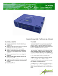
APL2400-200 User’s Manual
Version 1.3
1
APL2
APL240000-200
UltraSpeed CoaxLine Quad
Ethernet NetBridge™
TM
User’s Manual
Version 1.3
TM
APL2400-200 User’s Manual
Version 1.3
2
IMPORTANT SAFETY INSTRUCTIONS
1.
2.
3.
4.
5.
6.
7.
8.
Please read all instructions before installing and operating APL2400-200 and keep all
instructions for later reference.
Please follow all warnings and instructions marked on the product.
Unplug the AC coupler from the wall outlet before cleaning. Use a damp cloth for
cleaning. DO NOT use liquid cleaners or aerosol cleaners.
DO NOT operate APL2400-200 near water.
APL2400-200 should never be placed near or over a radiator, or heat register.
APL2400-200 relies on the building’s electrical installation for short-circuit (over current)
protection.
Ensure that a fuse or circuit breaker no larger than 120 VAC 15A or 240 VAC 6A is used on
the phase conductors (all current-carrying conductors).
DO NOT allow anything to rest on the APL2400-200 interconnect cables. DO NOT locate
APL2400-200 where people may walk on the cables.
9. APL2400-200 has its own power filter for protection against surges.
10. APL2400-200 is NOT field serviceable and should not be opened under any circumstance.
Opening or removing covers may result in exposure to dangerous voltage points or other risks.
11. Unplug the AC coupler from the wall outlet and refer the product to qualified service
personnel for the following conditions:
When the interconnect cords are damaged or frayed.
If liquid has been spilled into the product.
If the product has been exposed to rain or water.
If the product does not operate normally when the operating instructions are followed.
If the product exhibits a distinct change in performance.
APL2400-200 User’s Manual
Version 1.3
3
Copyright © 2009 by Aboundi Inc. All rights reserved.
No part of this documentation may be reproduced in any form or by any means or used to make any
derivative work (such as translation, transformation, or adaptation) without written permission from
the copyright owner.
All the other trademarks and registered trademarks are the property of their respective owners.
Statement of Conditions
The content described in this manual may be improved or changed at any time and it is subject to be
changed without notice.
Manufacturer assumes no responsibility for errors contained herein or for direct, indirect, special,
incidental or consequential damages with the furnishing, performance, or use of this manual or
equipment supplied with it, even if manufacturer of its suppliers have been advised of the
possibility of such damages.
Electronic Emission Notices
This device complies with Part 15 of the FCC Rules. Operation is subject to the following two
conditions:
(1) This device may not cause harmful interference.
(2) This device will accept any interference received, including interference that may cause
undesired operation.
APL2400-200 User’s Manual
Version 1.3
4
Table of Content
1.
Introduction .......................................................................................................... 5
1.1.
1.2.
Features ............................................................................................................................ 5
Product Kit ....................................................................................................................... 6
1.3.
1.4.
LED.................................................................................................................................. 6
Hardware Installation ........................................................................................................ 7
1.5.
Application ....................................................................................................................... 8
2.
Software Installation ............................................................................................. 9
2.1.
2.2.
3.
4.
System Requirements........................................................................................................ 9
Installation ........................................................................................................................ 9
Web Configuration.............................................................................................. 12
3.1.
Start-up and Log in ......................................................................................................... 12
3.2.
3.3.
3.3.1.
3.3.2.
3.3.3.
3.3.4.
3.4.
3.5.
3.6.
3.7.
Connection Info .............................................................................................................. 13
Configuration.................................................................................................................. 14
Security Page .................................................................................................................. 15
Network Page ................................................................................................................. 16
VLAN Page .................................................................................................................... 17
QoS Page ........................................................................................................................ 18
Change Password............................................................................................................ 19
Firmware Upgrade .......................................................................................................... 20
Factory Reset .................................................................................................................. 21
Reboot ............................................................................................................................ 22
Default Settings .................................................................................................. 22
APL2400-200 User’s Manual
Version 1.3
5
1. Introduction
The Aboundi APL2400-200 UltraSpeed™ CoaxLine™ Quad Ethernet NetBridge™ allows utilizing
the coaxial cable lines already deployed in a building as the network infrastructure connections. The
APL2400-200 provides reliable network quality and enables IP Cameras, Video Servers, POS,
Media Converters, Printers, Digital Signages and Network Equipments for easy broadband access in
a tight cluster space.
The APL2400-200 NetBridge™ can be quickly installed for commercial applications require high
bandwidth and critical demand of reliable network connection (QOS). This networking group can
be easily reallocated without the need to rewire “home run” Ethernet drops to such cluster group
locations.
The APL2400-200 NetBridge™ is designed specifically for small cluster networking applications
by providing four MDI/MDIX auto detection RJ-45 ports that can connect to any 10/100Mbps
Ethernet ports on the computer and other peripheral devices. The network over the coaxial cables
can convert to the existing power line with ACX1000 VersatileWire™ Adaptor to work with all
Aboundi UltraSpeed™ series NetBridge™. This capacity provides the flexibility to enhance your
network to be ubiquitous to everywhere in the building.
1.1. Features
Four shielded RJ-45 MDI/MDIX auto detection Ethernet Ports
Up to 200Mbps speed over the existing coaxial cables
Integrated Quality of Service (QOS) allows reliable triple play applications
Reliable and cost effective network
Supports up to sixteen APL2400-200 devices on one network domain
168-bit Tri-DES encryption for secure data transmission
Network segmentation through network identifier
Ident-and-Connect™ feature allows ease of network scan and network segmentation
Web based configuration
Up to 2.5 KM of operational distance
Compliance with IEEE802.3 10BASE-T, IEEE802.3u 100BASE-TX , UPA
Fully compatible with Aboundi UltraSpeed™ series PowerLine NetBridge™
APL2400-200 User’s Manual
Version 1.3
6
1.2. Product Kit
Before starting installation, please make sure the APL2400-200 package includes the following five
items:
1)
2)
3)
4)
5)
6)
Quick Installation Guide
APL2400-200 unit
CD-ROM (containing Ultra NetBridge™ Utility for Windows and User’s Manual).
Cat 5e cable
Power cord
BNC to F adaptor
If anything from the above items is missing, please contact your vendor.
1.3. LED
The following figure shows the APL2400-200 LED indicator.
The function for each LED is described as follow:
PWR-Green:
On when the power is on.
LNK/ACT-Blue:
On when PowerLine Link speed over 12Mbps,
Purple:
On when PowerLine Link speed between 12Mbps and 6 Mbps,
Amber:
On when PowerLine Link speed under 6Mbps,
Blinking when PowerLine activity is detected.
LNK/ACT-Green: On when Ethernet link is detected;
Blinking when Ethernet Activity is detected
APL2400-200 User’s Manual
Version 1.3
7
1.4. Hardware Installation
Step 1
Plug the included Ethernet network cable into the computer’s Ethernet port.
Step 2
Plug the other end of this cable into the Ethernet port of the APL2400-200.
Step 3
Plug the power cord into the electrical port of APL2400-200
Step 4
Connect the coaxial cable with F-type male connector.
Step 5
Plug the power plug into the AC socket on the wall.
APL2400-200 User’s Manual
Version 1.3
8
1.5. Application
Example – CCTV Application
APL2400-200 enables to extend the new IP Camera to run over the existing long distance coaxial
cable infrastructure and the extension of the ubiquitous Ethernet applications through coaxial cable
deployment already in existence. APL2400-200 also turns any existing analog video cable into a
high-speed Ethernet connection. This allows multiple network cameras to replace a single analog
CCTV camera without installing any new cable. Additionally, you’ll extend the coverage of the
surveillance system by simply branching the cabling with coaxial cable splitters.
• Innovative - Up to 200Mbps speed over existing coaxial cables
• Adaptive - No RF interference to the network
• Extensive - At least 2000 meters connection range
APL2400-200 User’s Manual
Version 1.3
9
2. Software Installation
Please follow the steps described in this section to install your Ultra NetBridge™ Utility.
2.1. System Requirements
Before installing Ultra NetBridge™ Utility, make sure the PC meets these requirements for
hardware installation:
Microsoft Windows* 98SE, ME, 2000, XP or Vista
Pentium® 166 MHz processor, equivalent or higher
One free Ethernet port for UltraSpeed™ Series PowerLine NetBridge™
30M free disk space
Only supported network components are installed:
Network Clients: Client for Microsoft Networks, Client for Netware Networks
Network services: File and print sharing for Microsoft Networks
Network protocols: Microsoft’s TCP/IP, IPX/SPX, NetBEUI, or Net BIOS support for
IPX/SPX
2.2. Installation
Before the installation, please close the application (if an older version is running) and uninstall it.
To install the application just run the setup executable program Setup.exe in the Product CD-ROM,
and follow the steps of the installation wizard. To start the Ultra NetBridge™ Utility installation,
press “Next>”:
APL2400-200 User’s Manual
Version 1.3
10
Next screen allows you to select the installation folder for the application. Click “Next>” to start
the installation:
Please wait for Installation progress bar finish. Press “Cancel” button to abort the installation
process.
APL2400-200 User’s Manual
Version 1.3
11
Utility has been installed. Press “Finish” to start the application:
Run the Utility
After installed the utility, please run the utility from Start / Programs or double-click the Ultra
NetBridge™ Utility icon
as shown in Figure 2.2. There is utility user guide which has
installed at same place. Please use adobe reader to open and read it for detail of the software.
Figure 2.2 Ultra NetBridge™ Utility
APL2400-200 User’s Manual
Version 1.3
12
3. Web Configuration
The APL2400-200 UltraSpeed™ NetBridge™ provides Web based configuration by your PC Web
browser, such as Microsoft Internet Explorer. This approach can be adopted in any MS Windows,
Mac or UNIX based platforms. You can configure the NetBridge™’s IP address using the Ultra
Netbridge™ Utility before they use the Web Configuration.
3.1. Start-up and Log in
Activate your browser, enter the IP address of NetBridge™ in the Location (for Netscape) or Address
(for IE) field and press ENTER. For example: http://192.168.1.176.
After the connection is established, you will see the web user interface of NetBridge™. At the
Password filed, enter the password (the factory default value is admin) and then click Log in
Figure 3.1.1 User Main Menu
APL2400-200 User’s Manual
Version 1.3
13
If the password is correct, the web appearance will be changed as shown in Figure 3.1.2. As listed in its
Connection Info page, there are several options for system administration.
Figure 3.1.2 Connection Info Page
3.2. Connection Info
The Connection Info page displays basic Information about the NetBridge™
1.
General Information: MAC and IP addresses and the number of boots.
2.
Available Connections: Display the list of all NetBridge™ devices discovered on the current
logical power line or coax networks and the connectivity status.
APL2400-200 User’s Manual
Version 1.3
14
3.3. Configuration
The Configuration page displays the current settings of the NetBridge™ including Security, Network,
VLAN, QoS, System Information.
Figure 3.3 Connection Info Page
APL2400-200 User’s Manual
Version 1.3
15
3.3.1. Security Page
The Security page enables you to modify the Network Identifier, Encryption Key and the Mac mode.
displays the current settings of the NetBridge™ including Security, Network, VLAN, QoS and System
Information.
Figure 3.3.1 Security Page
APL2400-200 User’s Manual
Version 1.3
16
3.3.2. Network Page
The Network page enables you to modify the network settings of the NetBridge™.
Figure 3.3.2 Network Page
APL2400-200 User’s Manual
Version 1.3
17
3.3.3. VLAN Page
The VLAN page enables you to modify the VLAN configuration of the NetBridge™.
Figure 3.3.3 VLAN Page
APL2400-200 User’s Manual
Version 1.3
18
3.3.4. QoS Page
The QoS page enables you to modify the QoS configuration of the NetBridge™.
Figure 3.3.4 QoS Page
APL2400-200 User’s Manual
Version 1.3
19
3.4. Change Password
You can change the administration password for the NetBridge™ in the Change Password page.
Figure 3.4 Change Password Page
APL2400-200 User’s Manual
Version 1.3
20
3.5. Firmware Upgrade
You can upgrade the firmware for the NetBridge™ in the Firmware Upgrade page.
Figure 3.5 Firmware Upgrade Page
APL2400-200 User’s Manual
Version 1.3
21
3.6. Factory Reset
You can reset the NetBridge™ to the factory default settings from the Factory Reset page.
Figure 3.6 Factory Reset Page
APL2400-200 User’s Manual
Version 1.3
22
3.7. Reboot
You can reboot the NetBridge™ remotely from the Reboot page.
Figure 3.7 Reboot Page
4. Default Settings
Administration Password: admin
IP Address: 0.0.0.0
Network Identifier: Electric-Connect
Mac Node: Client