1
(8527+(50
'5,9(6
3URGXFW0DQXDO
&RS\ULJKW (XURWKHUP 'ULYHV /LPLWHG All rights strictly reserved. No part of this document may be stored in a retrieval system, or transmitted in any form or by any means to persons not
employed by a Eurotherm group company without written permission from Eurotherm Drives Ltd.
Although every effort has been taken to ensure the accuracy of this document it may be necessary, without notice, to make amendments or correct
omissions. Eurotherm Drives cannot accept responsibility for damage, injury, or expenses resulting therefrom.
3ULQWHG LQ (QJODQG
+$
,VVXH
&KDSWHU*HQHUDO'HVFULSWLRQ
&KDSWHU
*HQHUDO'HVFULSWLRQ
The Eurotherm Drives Inverters described in this manual are suitable for the speed control of
standard 3-phase induction motors.
The Inverters use advanced microprocessor based technology to generate a variable frequency
variable voltage output, the control algorithm combining unique space Vector Pulse Width
Modulation control strategy with quiet pattern operation. The Inverters' control terminals are
galvanically isolated from power circuits to allow easy system interconnection. The controller is
protected against both phase to phase and phase to earth short circuits, overloads, and excessive
voltages via an intelligent monitoring strategy, thus avoiding nuisance tripping and giving trouble
free operation.
The Inverters require either a single phase 2 wire supply of 220/240 Volts, 50/60Hz or a 3-phase
3 wire supply, at 220/240V, 50/60Hz.
The 582 is available in two versions:
i)0.37/0.55kW single phase supply only
ii)
0.55/0.75kW single or 3-phase supply possible
The 583 is available in two versions:
i)1.1/1.5kW single or 3-phase supply
ii)
1.5/2.2kW single or 3-phase supply
The 5831 is available in two versions:
i)0.37/0.55/0.75kW single or 3-phase supply
ii)
1.1/1.5kW single or 3-phase supply
All versions feature power derating by simple switch selection. Note that all controllers are
shipped with the switches set to the lower rating.
The Inverters' output frequency ranges from 0 - 100/120Hz with varying voltage/frequency
characteristics suitable for either constant torque applications or efficient operation of fans and
centrifugal pumps.
The 582/583 Inverters are available in either IP00 or IP20 enclosures. The IP20 version can be
supplied with the basic operator controls of speed demand, direction and start/stop, requiring
only the power connections to be made to give a working system.
The 5831 is the IP54 version of the Inverter family. It can be supplied as a simple enclosed
version or with basic operator controls.
An option card is also available which can be fitted in the inverter to allow use of a current
reference instead of the standard voltage reference.
The inverters are fully compliant with the requirements of the EMC directive. As standard they
meet the industrial immunity requirements of the draft generic standard prEN50082-2 (1992),
and with the addition of filters, and correct installation meet the ‘residential, commercial and
light industrial’ emission requirements of the generic standard EN50081-1 (1992).
:$51,1*
Dangerous voltages remain present in the drive for a few minutes after power is removed, as
indicated by the link charge LED. Allow 5 minutes after the power is removed for the link
capacitors to discharge before working on the drive or ancillary equipment.
***** DO NOT CONNECT TO 415V SUPPLY. USE ONLY 220/240V *****
:$55$17<
Eurotherm Drives warrants the goods against defects in design, materials and workmanship for the period of 12
months from the date of delivery on the terms detailed in Eurotherm Drives Standard Conditions of Sale IA058393C.
Eurotherm Drives reserves the right to change the content and product specification without notice.
COPYRIGHT in this document is reserved to Eurotherm Drives Ltd.
,17(1'('86(56
This manual is to be made available to all persons who are required to configure, install or service the equipment described
herein or any other associated operation.
WARNING
This equipment contains hazardous voltages and hazardous rotating mechanical components.
Loss of life, severe personal injury or property damage can result if instructions contained in
this manual are not followed.
Only qualified personnel should work on this equipment, and only after becoming familiar
with all safety instructions regarding installation, operation and maintenance procedures
contained in this manual. The successful and safe operation of this equipment is dependent on
proper handling, installation, operation and maintenance of the equipment.
&RQWHQWV
&KDSWHU *HQHUDO 'HVFULSWLRQ
&KDSWHU 7HFKQLFDO 'HWDLOV
(/(&75,&$/ 63(&,),&$7,216 (19,5210(17$/ 0(&+$1,&$/ &KDSWHU 2XWOLQH 'UDZLQJV
&KDSWHU 3URGXFW &RGH
&KDSWHU 7HUPLQDO 'HVFULSWLRQV
7(50,1$/ '(6&5,37,216 7(50,1$/ '(6&5,37,216 32:(5 7(50,1$/6 &86720(5 $'-8670(176 237,21 6:,7&+(6 &KDSWHU 'LDJQRVWLFV
%/2&. ',$*5$0 ++
%/2&. ',$*5$0 ++
%$6,& &211(&7,21 :,7+ %5$.( 81,7 +-
%$6,& &211(&7,21 :,7+ %5$.( 81,7 +-
%$6,& &211(&7,21 +-
020(17$5< 67$576723 +-
&KDSWHU ,QVWDOODWLRQ ,QIRUPDWLRQ
02725 :,5,1* 63(&,$/ &216,'(5$7,216 )25 8/ &203/,$1&( &KDSWHU %DVLF 6HWWLQJ 8S 3URFHGXUH
&$87,21 35(3$5$7,21 32:(5 21 $33/,&$7,216 127(6 $1' +,176 &KDSWHU 7URXEOH 6KRRWLQJ
&KDSWHU 8VHU ,QVWUXFWLRQV
&855(17 /223 $1' =(52 63((' 237,21 &$5' &KDSWHU (0& DQG WKH ¶&(· 0DUN
&
W
,66
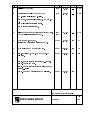
02',),&$7,21
(&1 1R
'$7(
'5$:1
&+.
'
,QLWLDO ,VVXH RI +$
*'5
&RUUHFWLRQV 3DJH %ORFN QRZ ´µ
*'5
5HSODFHG 66' QDPH DQG DGGUHVV ZLWK (XURWKHUP 'ULYHV
*'5
$GG 8/ VSHFLDO FRQVLGHUDWLRQV SDJH )(3
&&
1R 2SVWDWLRQ ´µ ,QFOXGLQJ 2SVWDWLRQ
3DJH 0D[ &XUUHQW 6XSSO\ FKDQJHG WR DQG WR 3DJH *ODQG 3ODWH IRUFH ILW LQWR ´EDVHµ
3DJH 5HYLVHG &LUFXLW 'LDJUDP
$GGHG WR SDJH QXPEHU 5HZULWWHQ IURP 0DQXVFULSW WR 0LFURVRIW :RUG $GGHG VHFWLRQ (0& DQG WKH ¶&(· 0DUN
)(3
03
3DJH FRUUHFWHG WR N: RQ N:
EXLOG GULYH
)(3
5%U
3DJH DGGHG VHQWHQFH ´DV FRQILUPHG FKDSWHU
)(3
3DJH DGGHG QHZ FKDUW
3DJH DGGHG ´*HQHULF 6WDQGDUGµ FROXPQV DQG ´
$FKLHYHG FDEOHµ
3DJH DGGHG 0DQXIDFWXUHUV (0& 'HFODUDWLRQ
),567 86(' 21
02',),&$7,21 5(&25'
3URGXFW 0DQXDO
'5$:,1* 180%(5
(8527+(50'5,9(6
==
6+7 2) &KDSWHU7HFKQLFDO'HWDLOV
&KDSWHU
7HFKQLFDO'HWDLOV
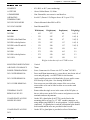
(/(&75,&$/ 63(&,),&$7,216
3$5$0(7(5
1$
N:
N:
N:
N:
81,76
N:
N:
/$
8
/$
8
&+
$
&+
$
/$
8
/$
8
&+
$
&+
$
,1387
5$7,1*6
6XSSO\ 9ROWDJH
RU SKDVH
0D[ 6XSSO\ &XUUHQW
SK
SK
)XVH $VVHPEO\ SK /$ /$ /$ /$
8
8
8
8
)XVH $VVHPEO\ SK
/$ /$
8
8
)XVH 5HSODFHPHQW &+ &+ &+ &+
SK
$
$
$
$
)XVH 5HSODFHPHQW
&+ &+
SK
$
$
6XSSO\ )UHTXHQF\
3RZHU )DFWRU ODJ
9ROWV $&
$PSV $&
506
SHU
SKDVH
SHU
SKDVH
+]
287387
5$7,1*6
2XWSXW 5DWLQJV
9ROWV $&
0D[ 2XWSXW &XUUHQW
$PSV $&
2XWSXW )UHTXHQF\ +]
+HDW 'LVVLSDWLRQ
:DWWV
2XWSXW 3RZHU
N:
2YHUORDG
V
V
V
V
V
V
&KDSWHU7HFKQLFDO'HWDLOV
(19,5210(17$/
HUMIDITY
:
85% R.H. at 40°C (non condensing).
ALTITUDE
:
Above 1000m Derate 1%/100m.
ATMOSPHERE
:
Non- flammable, non-corrosive and dust free.
OPERATING
TEMPERATURE
:
0 to 40°C (Derate 1.5%/Degree above 40°C up to 55°C).
582/583 ENCLOSURE
:
Chassis Mounted either IP00 or IP20.
5831 ENCLOSURE
:
Panel Mounted IP54.
0(&+$1,&$/
Width(mm)
Height(mm)
Depth(mm)
Weight(kg)
582 IP00
:
163
237
84
1.0(1.2)
582 IP20
:
170
247
97
1.9(2.1)
582 IP20 with Gland Plate
:
170
280
97
2.1(2.3)
582 IP20 with Op Station
:
170
247
117
1.9(2.1)
582 IP20 with GP and OS
:
170
280
117
2.1(2.3)
583 IP00
:
272
250
156
4.6
583 IP20
:
272
250
165
5.2
583 IP20 with Op Station
:
272
250
185
5.3
5831 IP54
:
188
255
150
5.5
Weights in brackets refer to 0.75kW version
MOUNTING ORIENTATION
:
Vertical
AIR FLOW CLEARANCE
:
70mm
POWER TERMINATIONS
:
Screw Connectors for 2.5mm wire 5822 or 4mm2 583/5831.
582 COVER REMOVAL:
:
Press small blunt instrument (e.g. screwdriver) into slot in side of
cover and pull gently - see HG057848 for slot location.
583 COVER REMOVAL
:
Apply sensible pressure to left-hand side of cover until it comes
free from lip of side plate. See drawing HG058065F.
5831 COVER REMOVAL
:
Four screws are provided at the corners of the cover when
removed the cover can be lifted to allow access to the earth
connection.
TERMINAL PLATE
REMOVAL 582/583
:
Rotate either the single screw in the centre of the 583 plate, or
the two side screws on the 582 to remove and gain access to the
terminals and user adjustments.
GLAND PLATE ACCESS
HOLES 582 ONLY
:
On the 582 a gland plate (LA057730) can be fixed to the
mounting plate to accept 3 x 0.5” NPT conduit connectors, or,
using adaptor ring BH058121 in each position, 3 x M20 conduit
connectors. If a gland plate is used the old terminal plate should
be discarded and the new one provided in the kit used.
GLAND PLATE ACCESS
5831
:
On the 5831 a gland plate is provided as a force fit into base.
&KDSWHU7HFKQLFDO'HWDLOV
&KDSWHU2XWOLQH'UDZLQJV
&KDSWHU
2XWOLQH'UDZLQJV
+*(,32XWOLQH'UDZLQJ
+*)0DQXDO2XWOLQH'UDZLQJ
+*),32XWOLQH'UDZLQJ
+*),32XWOLQH'UDZLQJ
+*)2XWOLQH'UDZLQJ
&KDSWHU3URGXFW&RGH
&KDSWHU
3URGXFW&RGH
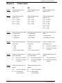
Block 1
3 Digits identifying basic
product (582)
3 Digits identifying basic
product (583)
4 Digits identifying basic
product (5831)
Block 2
4 Digits identifying the
output power.
4 Digits identifying the
output power.
4 Digits identifying the
output power.
0375 - 0.375kW
1100 - 1.1kW
0375 - 0.375kW
0550 - 0.55kW
1500 - 1.5kW
0550 - 0.55kW
0750 - 0.75kW
2200 - 2.2kW
0750 - 0.75kW
1100 - 1.1kW
1500 - 1.5kW
Block 3
Block 4
Block 5
Block 6
Single digit specifying single Single digit specifying single Single digit identifying Opor 3-phase input.
or 3-phase input.
station.
1 - single phase
1 - single phase
1- No Op-station
3 - three phase
3 - three phase
2 - Including Op-station
Single digit specifying type
of enclosure.
Single digit specifying type
of enclosure.
2 Digits to indicate option
card requirements.
0 - IP00
0 - IP00
00 -
No option card fitted
1 - IP20
1 - IP20
01 -
2 - IP20 with Op-station
2 - IP20 with Op-station
Current Loop Option
(4 -20mA)
2 Digits to indicate option
card requirements.
2 Digits to indicate option
care requirements.
2 Digits identifying special
options.
00 -
No option card fitted
00 -
No option card fitted
00 -
01 -
Current Loop Option
(4 - 20mA)
01 -
Current Loop Option
(4 - 20mA)
01 - 99 Documented special
options
2 Digits identifying special
options
2 Digits identifying special
options.
00 -
00 -
No special options
01 - 99 Documented
special options
No special options
No special options
01 - 99 Documented
special options
&KDSWHU7HUPLQDO'HVFULSWLRQV
&KDSWHU
7HUPLQDO'HVFULSWLRQV
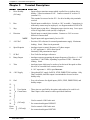
7(50,1$/ '(6&5,37,216 1.
Drive Healthy
(582 only)
: Open collector transistor output which is pulled low to indicate drive
healthy. 250mA maximum at 24V. Connect external 0V to drive 0V
(terminal 11).
This terminal is not used on the 583. See drive healthy relay terminals
overleaf.
2.
Run
: Digital input to enable drive: Switch to +24V to enable. Connection via
momentary contact may be employed; see diagram number HJ385167D.
3.
Stop
: Digital input to stop drive: Momentary open circuit to stop. Leave open
circuit if single Run switch (on/off) is employed.
4.
Direction
: Digital input to control phase rotation: Connect to +24V to reverse
direction of motor shaft.
Digital inputs sink approximately 5mA at 24V.
NOTE
5.
+10V Ref
: Precision 10V reference for external potentiometer supply. Maximum
loading: 10mA. Short circuit protected.
6.
Speed Setpoint
: Analogue input to control frequency of 3-phase output.
0 - 10V represents 0 - 100% motor speed.
Nominally 10K potentiometer input.
7.
0V Ref
: Zero Volts for analogue references.
8.
Ramp Output
: Analogue output representing the output frequency of the drive. 0 - 10V
represents 0 - 100/120Hz, depending on position of SW1. Maximum
loading: 10mA.
9.
Trim
: Analogue input which may be used as a local trim of the speed to allow
drives to be cascaded from a master reference.
0 - 10V represents 0 - 100% speed increase.
10. +24V Supply
: Unregulated 24V supply for RUN, STOP, DIRECTION switches. Only
20mA available, thus this output is not intended to be used to drive
healthy relay.
11. Gnd
: Zero volt reference for digital inputs, (RUN, STOP, DIRECTION) and
healthy output.
12.
13.
14.
User Option
Connections
: These pins are specified by the option cards and may be used for a 4 20mA input. serial comms or other specialised functions.
(583 only)
:
15.
16.
17.
Used to control a 5801 brake unit.
18.
Hesto
Conn.
See connection diagram HJ058055.
Used to control a 5801 brake unit.
(582 only)
:
See connection diagram HJ057820.
&KDSWHU7HUPLQDO'HVFULSWLRQV
All terminals are suitable for 2.5mm wire (12 AWG) recommended tightening torque 0.5Nm (4.5 lb-in).
2
7(50,1$/ '(6&5,37,216 1.
Run
: Digital input to enable drive: Switch to +24V to enable. See diagram
number HJ385002D.
2.
Stop
: Digital input to stop drive: Momentary open circuit to stop. Leave open
circuit if single Run switch (on/off) is employed.
3.
Direction
: Digital input to control phase rotation: Connect to +24V to reverse
direction of motor shaft.
Digital inputs sink approximately 5mA at 24V.
NOTE
4.
+10V Ref
: Precision 10V reference for external potentiometer supply. Maximum
loading: 10mA. Short circuit protected.
5.
Speed Setpoint
: Analogue input to control frequency of 3-phase output.
0 - 10V represents 0 - 100% motor speed.
Nominally 10K potentiometer input.
6.
0V Ref
: Zero Volts for analogue references.
7.
Ramp Output
: Analogue output representing the output frequency of the drive. 0 - 10V
represents 0 - 100/120Hz, depending on position of SW1. Maximum
loading: 10mA.
8.
Trim
: Analogue input which may be used as a local trim of the speed to allow
drives to be cascaded from a master reference.
0 - 10V represents 0 - 100% speed increase.
9.
+24V Supply
10. Gnd
: Unregulated 24V supply for RUN, STOP, DIRECTION switches. Only
20mA available, thus this output is not intended to be used to drive
healthy relay.
: Zero volt reference for digital inputs, (RUN, STOP, DIRECTION) and
healthy output.
11.
12.
User Option
Connections
13.
14.
: These pins are specified by the option cards and may be used for a 4 20mA input. serial comms or other specialised functions.
15.
16.
Used to control a 5801 brake unit.
:
17.
See connection diagram HJ385002.
All terminals are suitable for 2.5mm2 wire (12 AWG) recommended tightening torque 0.5Nm (4.5 lb-in).
&KDSWHU7HUPLQDO'HVFULSWLRQV
32:(5 7(50,1$/6
Input Terminals
:
L1 (L)
L2 (N)
L3
220/240V AC ± 10%
Single phase L and N
3-phase L1, L2, L3
Brake Connections
:
DC +
DC -
DC Link Positive
DC Link Negative
Motor Connections
:
M1 (U)
M2 (V)
M3 (W)
3-Phase
0 to 220/240V AC
0 to 100/120HZ
NOTE: The 582 has no chassis ground except when a gland plate is fitted. Power terminal blocks
are suitable for 2.5mm2 wire (12 AWG) recommended tightening torque 0.5Nm (4.5 lb-in).
Input Terminals
:
L1 (L)
L2 (N)
L3
220/240V AC ± 10%
Single phase L and N
3-phase L1, L2, L3
Brake Connections
:
DC +
DC -
DC Link Positive
DC Link Negative
Health Relay
Health Relay
HEALTH2
Motor Connections
:
M1 (U)
M2 (V)
M3 (W)
Contact rating 3A 250V AC/30V DC
3-phase
0 to 220/240V AC
0 to 100/120Hz
NOTE: The 583 can be grounded at the heatsink. Power Terminal Blocks are suitable for 4mm2 wire
(10 AWG) recommended tightening torque 0.5Nm (4.5 lb-in).
Input Terminals
:
L1 (L)
L2 (N)
L3
220/240V AC ± 10%
Single phase L and N
3-phase L1, L2, L3
Motor Connections
:
M1 (U)
M2 (V)
M3 (W)
3-phase
0 to 220/240V AC
0 to 100/120Hz
Health Relay
Health Relay
HEALTH2
Brake Connections
(Faston Connectors)
:
DC +
DC -
Contact rating 3A 250V AC/30V DC
DC Link Positive
DC Link Negative
NOTE: The 5831 can be grounded at the base plate. Power terminal blocks are suitable for 4mm2
wire (10 AWG) recommended tightening torque 0.5Nm (4.5 lb-in).
NOTES:
1.
2.
The ground terminal is indicated by the IEC grounding symbol thus:Contacts closed when drive is healthy.
&KDSWHU7HUPLQDO'HVFULSWLRQV
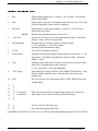
&86720(5 $'-8670(176
P1
Low Speed/Frequency Voltage :
Boost
VB
P2
Current Limit
:
Rotate clockwise to increase the maximum current available
from the drive. If current demand exceeds current limit, the
speed/frequency will be reduced to keep the current within
this maximum.
Adjustment 50% to 150% of rated current.
Note: Motor may not turn if turned fully anti-clockwise.
:
Rotate clockwise to increase maximum speed/frequency at
which drive will run with 100% speed demand.
Adjustment is from 0 - 100/120Hz.
In the event of conflict between Minimum and Maximum
settings, Maximum will always override.
:
Rotate clockwise to increase minimum speed/frequency at
which drive will run with zero speed demand.
Adjustment is from 0 - 100/120Hz.
I∆
P3
Maximum Speed
N∆
P4
Minimum Speed
Rotate clockwise to increase the voltage/frequency ratio at
low speed; this gives the motor more low speed torque.
Excessive adjustment may cause the current limit to be
reached and the motor may not turn.
N∇
P5
Ramp Up Time
:
Rotate clockwise to increase the time taken to ramp up to
speed/frequency.
Output adjustment range is either 0.1 - 4 seconds or 2.5 100 seconds depending upon position of switch 4.
P6
Ramp Down Time
:
Rotate clockwise to increase the time taken to ramp down to
speed/frequency.
Output adjustment range is either 0.1 - 4 seconds or 2.5 100 seconds depending upon position of switch 5.
:$51,1*
THE SIX TRANSISTOR HEATSINKS OF THE 582 ARE LIVE. CARE SHOULD BE
TAKEN WHEN MAKING ADJUSTMENTS TO AVOID CONTACT WITH THESE PARTS.
&KDSWHU7HUPLQDO'HVFULSWLRQV
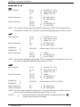
237,21 6:,7&+(6
Switch positions are only read at power-on, so if any adjustment of switches is required, the power
must be removed before doing so.
(OFF)
SW1
50Hz
:
60Hz
Base Frequency
(ON)
SW2
(OFF)
:
SW3
(OFF)
Normal
:
V
Max Speed
Min Speed
F
SW2
(OFF)
SW3
(ON)
Linear
:
2F
V
Max Speed
Min Speed
F
SW2
(ON)
SW3
(OFF)
Fan Law
2F
V
Max Speed
Min Speed
F
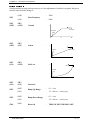
SW2
(ON)
SW4
SW3
(ON)
(OFF)
Reserved
Ramp Up Range
(ON)
SW5
(OFF)
Ramp Down Range
(ON)
SW6
(OFF)
2F
Reserved
:
0.1 - 4 sec
:
2.5 - 100 sec to base freq.
:
0.1 - 4 sec
:
2.5 - 100 sec to base freq.
:
THIS SW MUST REMAIN OFF.
&KDSWHU7HUPLQDO'HVFULSWLRQV
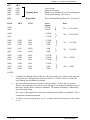
SW7
(OFF)
(OFF)
(ON)
(ON)
SW8
(OFF)
(ON)
(OFF)
(ON)
SW9
- Stopping Mode
Ramp Hold
SW10
SW11
:
:
:
:
Coast to Stop.
Ramp down to Stop.
Ramp to zero followed by 2 sec DC holding pulse.
DC Injection Braking. (See Note 2).
:
This switch should normally be off. (See Note 3).
SW12
(OFF)
(ON)
Power
Output
0.37kW
0.55kW
:
(OFF)
(ON)
Drive
582
0.37/0.55kW1
:
0.55kW
0.75kW
582
0.55/0.75kW1
(OFF)
(ON)
(ON)
(OFF)
(OFF)
(ON)
(ON)
(ON)
(ON)
:
:
:
0.75kW
1.1kW
1.5kW
583
1.1/1.5kW1
(OFF)
(ON)
(ON)
(ON)
(OFF)
(OFF)
:
:
1.5kW
2.2kW
583
1.5/2.2kW1
(OFF)
(ON)
(ON)
(OFF)
(OFF)
(ON)
(ON)
(ON)
(ON)
:
:
:
0.37kW
0.55kW
0.75kW
5831
0.75kW1
(OFF)
(ON)
(ON)
(OFF)
(OFF)
(ON)
(ON)
(ON)
(ON)
:
:
:
0.75kW
1.1kW
1.5kW
5831
1.5kW1
NOTES:
1.
Controllers are shipped with switches set to the lower rating. Set switches to the required
rating before use. Setting of the switches on the 583 1.1/1.5kW version to 2.2kW will
cause damage and invalidate the warranty.
2.
DC injection braking may be selected by setting switches 7 and 8 to the ‘on’ position.
When a stop command is received, the drive will apply a low frequency braking current to
the motor, until the shaft is almost at a standstill. The amount of braking is controlled by
the current limit setting.
DC current is then applied for a short time, to bring the shaft finally to a standstill. This is
controlled by the boost adjustment.
3.
To achieve very fast ramp up rates, e.g., 0.1 seconds, it may be necessary to set this switch
to ‘on’.
&KDSWHU'LDJQRVWLFV
&KDSWHU
'LDJQRVWLFV
LED1
Power On
:
Illuminated when power is present on drive.
LED2
Status
:
Illuminated when drive is healthy and running;
off when drive is healthy and disabled.
Alarm conditions are indicated via an optical
code flash sequence:
LED3
Instantaneous overcurrent
:
2 flashes followed by pause.
DC link overvoltage
:
3 flashes followed by pause.
Ixt overload
:
4 flashes followed by pause.
Motor stalled
:
5 flashes followed by pause.
Ixt integrator
:
Status LED flashing but drive still running
indicates that Ixt integrator is operating. The
drive will remain running only for a limited
period of time depending on the level of overload.
Healthy
:
Illuminated when drive is healthy.
Off in any alarm conditions.
NOTE:
The LED on the left of the drive indicates that there is still charge on the DC link
capacitor. While this LED is illuminated danger of electric shock exists. No work
must be carried out on the drive in this condition.
&KDSWHU,QVWDOODWLRQ,QIRUPDWLRQ
&KDSWHU
,QVWDOODWLRQ,QIRUPDWLRQ
Before connecting AC supply to this equipment.
1.
Ensure good airflow over heatsink. Maintain clearance above and below controller to
70mm.
2.
Operating temperature range 0 to + 40°C.
3.
Protect from airborne pollutants.
4.
Avoid vibration.
02725
1.
Ensure motor is mechanically secure and mounted according to manufacturers
specifications and practice.
2.
Ensure that motor is connected for 220/240V 3-phase operation.
3.
Check obstructions in motor vents to maintain cooling air path.
4.
Auxiliary cooling must be provided for motor if constant torque is required and low speed
operation is possible, see motor manufacturers derating specification.
5.
Ensure motor is free to rotate and that pulleys and couplings are correctly aligned.
6.
Ensure transit damage has not occurred to motor windings or connections. Disconnect the
controller before carrying out electrical measurements e.g., insulation resistance.
:,5,1*
1.
For EMC installation refer to the section “EMC and the CE Mark”.
2.
For information on the wiring of the controllers refer to:a) 582
-
HJ057820
b) 583
-
HJ058055
c) 5831
-
HJ385002
A general purpose diagram of momentary start/stop is given in diagram HJ385167.
3.
Control cabling 0.75 sq.mm. minimum.
4.
Power cable to be minimum 300V AC rated at 1.1 x controller current.
5.
HRC fuses or circuit breakers of the correct rating are recommended for incoming supply
protection.
6.
Isolated control wiring should not be run close to the power cabling. If screened cables are
used (recommended on setpoints and meters) connect screens to earth only at controller
end.
7.
Eurotherm Drives supply fuse assemblies which can be bulkhead mounted and also act as
convenient supply isolators. For fuse part numbers refer to Electrical Specification on
page 2-1. If preferred circuit breakers of appropriate rating may also be used as an
alternative to fuses.
8.
A cable assembly Eurotherm Drives reference LA056140 is required when connecting the
582 to the 5801 Brake Unit. The cable assembly consists of an insulation displacement
connector and a twisted pair of red and black cable. The insulation displacement
connector fits into the socket SK1 on the 582 and the red and black cable end connect to
the 5801. The red cable connects to D+, the black cable to D-.
&KDSWHU,QVWDOODWLRQ,QIRUPDWLRQ
63(&,$/ &216,'(5$7,216 )25 8/ &203/,$1&(
1.
Power Cabling to be rated at 1.25 x controller current.
2.
An external running motor overload protective device must be provided by the installer.
This device may be:i) A motor thermistor monitoring motor temperature.
ii) A thermal overload monitoring motor current.
iii) Any device which is considered adequate by the installer or local inspector to comply
with the National Electric Code and/or local code requirements.
3.
Where a protective ground terminal is provided as indicated by the IEC grounding symbol,
the controller should be grounded via a cable of suitable rating as defined by the National
Electric Code.
4.
Class T Branch Circuit fuses rated at 20A for 1.1 and 1.5kW controllers and 30A for
2.2kW controllers must be provided by the installer.
5.
583 Products are suitable for use on a circuit capable of delivering not more than 5000
RMS symmetrical amperes, 240 volts maximum.
&KDSWHU%DVLF6HWWLQJ8S3URFHGXUH
&KDSWHU
%DVLF6HWWLQJ8S3URFHGXUH
%()25( $77(037,1* 72 &211(&7 32:(5 &$5()8//< &+(&.
1.
Main power supply voltage is correct.
2.
Motor is of correct voltage rating and is connected in either star or delta as appropriate.
3.
All external wiring circuits:Power connections
Control connections
Motor connections
NOTE:- Completely disconnect the controller before point to point checking with a
buzzer or when checking insulation with a meggar.
4.
Check for damage to equipment.
5.
Check for loose ends, clippings, drilling swarf, etc., lodged in the drive or ancillary
equipment.
6.
If possible check that the motor can be turned freely and that cooling fan is intact and free
of obstructions.
&$87,21
1.
That rotation of the motor in either direction will not cause damage.
2.
That nobody else is working on another part of the equipment and will be affected by
powering up.
3.
That other equipment will not be adversely affected by powering up.
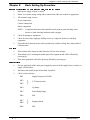
35(3$5$7,21
1.
Prevent application of the main power supply by removal of the supply fuses or isolate via
supply circuit breaker.
2.
Disconnect the load from the motor shaft, if possible.
3.
Check switch selection:SW1
Supply Frequency 50/60Hz.
SW2
SW3
V/F Characteristics.
SW4
Up Ramp.
SW5
Down Ramp Range.
SW6
OFF
SW7
SW8
Stopping Mode
SW9
OFF
&KDSWHU%DVLF6HWWLQJ8S3URFHGXUH
4.
SW10
SW11
SW12
Pots are set:-
Power Rating
Controllers are shipped from Eurotherm Drives
with switches set to the lower power rating for
each power rating.
P1
Boost
Anticlockwise
(no boost)
P2
Current Limit
Clockwise
(full current)
P3
Maximum Speed
Mid
(approximately base speed)
P4
Minimum Speed
Anticlockwise
(zero minimum speed)
P5
Ramp Up
Clockwise
(slow ramp)
P6
Ramp Down
Clockwise
(slow ramp)
5.
Check external run contacts are open.
6.
Check external setpoints are all zero.
32:(5 21
Once all the proceeding steps are completed and understood, the supply fuses/circuit breaker may be
replaced and power applied to the drive. Although fairly general, the following assumes a single drive
and motor configuration.
1.
At switch on the “Power ON” (LED 1) should illuminate as should DC Link charged LED.
2.
Close RUN contact, either give drive small speed demand via speed potentiometer or
rotate slightly clockwise minimum speed potentiometer. Motor should rotate slowly.
If motor rotates in wrong direction either:-
Swap two of the output phases (U, V, W).
Close direction switch.
Power down and hard wire terminal 4 to
terminal 10.
3.
With speed potentiometer set to zero set minimum speed to desired minimum running
speed of motor.
4.
On applications where high starting torque is required increase of low voltage BOOST
may be necessary. Excessive adjustment may cause drive to trip on over current and will
cause motor to overheat if left running in this condition.
5.
Set speed potentiometer to 100% and either increase or decrease maximum speed
potentiometer to set maximum running speed of the motor.
6.
By varying the speed demand potentiometer the ramp times may be set by adjustment of
Ramp Up/Down potentiometers.
7.
If Ramp down times cannot be achieved without the drive tripping on over voltage alarm,
then a 5801 brake unit must be fitted.
8.
Stopping modes may be selected via SW7 and SW8. Power must be removed before this
adjustment is made.
9.
If the motor used is rated below the rating of the inverter a reduction in current limit (anticlockwise adjustment of P2) will give electronic protection of the motor, and a crude form
of torque limit. If more than one motor is used, each must be protected via an appropriate
overload.
&KDSWHU%DVLF6HWWLQJ8S3URFHGXUH
$33/,&$7,21 127(6 $1' +,176
1.
Always use gold flash relays, or others designed for low current operation (5mA) on all
control wiring.
2.
Use screened cable on all control wiring.
3.
Place control and power wiring in different ducts.
4.
Isolation between inverter and motor may be employed although it is recommended that
this is operated when motor is stationary or in emergencies only. Note that dangerous
voltages are present within the drive for a few minutes after the power is removed.
5.
Occasionally a motor line-choke (582 - CO055930) (583 - CO055931) is recommended to
prevent nuisance over-current tripping when motor cables exceed 20m in length. 20m is a
nominal length; some installations may be better, others worse.
6.
All power factor correction equipment must be removed from the motor before an inverter
can be used.
7.
Motors with low efficiency and small cos o (power factor) should be avoided since they
require a larger KVA rated inverter to produce the correct shaft kW.
8.
On applications where synchronous, slip ring, pole change or brake motors are used, please
consult with Eurotherm Drives Limited prior to installation.
&KDSWHU7URXEOH6KRRWLQJ
&KDSWHU7URXEOH6KRRWLQJ
352%/(0
&RQWUROOHUZLOOQRW3RZHUXS
1R´3RZHU21µ/('
LOOXPLQDWHG
3266,%/(&$86(
6XSSO\IXVHVEUHDNHU
1RVXSSO\
,QFRUUHFWVXSSO\YROWDJH
5(0('<
:URQJUDWLQJ
&KHFNVXSSO\DYDLODELOLW\
&KHFNVXSSO\YROWDJH
02725:,//127581:+(132:(5$33/,('
$OO/($'621
1RPRWRUFRQQHFWLRQ
0D[LPXPVSHHGVHWDW]HUR
0RWRUMDPPHG
&KHFNPRWRUFRQQHFWLRQV
,QFUHDVHWRDSSUR[LPDWHO\
)UHHREVWUXFWLRQ
/('21
/('2))
/('21
5XQVZLWFKQRWFORVHG
&RQQHFWLRQZLWKPRPHQWDU\
SXVKEXWWRQVLQFRUUHFW
&KHFNFRQQHFWLRQEHWZHHQ
WHUPLQDODQG
&KHFNZLULQJ
%RRVWVHWWRRKLJK
5HGXFHERRVWVHWWLQJ
$FFHOHUDWLRQUDWHWRRKLJK
5HGXFHUDPSXSVHWWLQJ
0RWRUZLQGLQJVKRUWFLUFXLW
'LVFRQQHFWGULYHDQGPHJJDU
PRWRU
)/$6+(62YHUYROWDJH
6XSSO\YROWDJHWRRKLJK
'HFHOHUDWLRQUDWHWRRKLJK
&KHFNVXSSO\YROWDJH
5HGXFHUDPSGRZQVHWWLQJ
)LWEUDNHXQLW
&KHFNEUDNHXQLWDQGLWV
UHVLVWRUV
)/$6+(6,[W
2YHUVSHHGLQJIDQSXPS
5HGXFHPD[LPXPVSHHGVHWWLQJ
2YHUVL]HGPRWRUILWWHG
&KHFNPRWRUUDWLQJDQGSRVLWLRQ
RIVZLWFK
/RDGWRRODUJH
5HGXFHPRWRUVKDIWORDGLQJ
)/$6+(60RWRU6WDOOHG
&XUUHQWOLPLWWRRORZ
,QFUHDVHFXUUHQWOLPLWVHWWLQJ
/('´:LQNLQJµ
'ULYHLQRYHUORDGFRQGLWLRQ
/RDGWRRODUJH
%RRVWVHWWLQJWRRKLJK
5HGXFHPRWRUVKDIWORDGLQJ
LQFUHDVHUDPSXSWLPH
5HGXFHERRVWVHWWLQJ
/('21
/(')ODVKLQJ
/('2))
)/$6+(62YHUFXUUHQW
&KDSWHU7URXEOH6KRRWLQJ
352%/(0
3266,%/(&$86(
5(0('<
'&,1-(&7,21%5$.,1*',)),&8/7,(6
0RWRUVWDUWVWREUDNHWKHQ
FXWVRXWEHIRUHWKHEUDNLQJ
LVFRPSOHWHGOHDYLQJWKH
PRWRUWRFRDVWWRDVWRS
,QWHUQDOWLPHRXWKDVDFWHG
'XULQJWKHEUDNLQJ
VHTXHQFHWKHUDPSDFWVDV
DWLPHRXWE\UDPSLQJ
GRZQIURPWKHVHWSRLQWWR
]HUR7KHGULYHWKHQZDLWVD
IXUWKHUVHFRQGVDQGVWRSV
WKHGULYHLIWKHEUDNLQJLVQRW
FRPSOHWHG
,QFUHDVHUDPSGRZQWLPH
7LPHRXWZLOORSHUDWHLQUDPS
WLPHIURPVHWSRLQWSOXV
VHFRQGV
0RWRUEUDNHVDOPRVWWRD
VWDQGVWLOOEXWGRHVQRWTXLWH
VWRSEHIRUHWKHGULYHFXWV
RXW
1RWHQRXJKERRVW:KHQ
WKHVKDIWKDVDOPRVWUHDFKHG
VWDQGVWLOOWKHGHJUHHRI
EUDNLQJLVGHWHUPLQHGE\WKH
ERRVWSRW
,QFUHDVHERRVW
0RWRUUDWLQJVPDOOHUWKDQ
GULYHUDWLQJ
6HOHFWFRUUHFWUDWLQJRQ',/
VZLWFKHV
7XUQGRZQFXUUHQWOLPLW
1RWHQRXJKERRVW
,QFUHDVHERRVW
&XUUHQWOLPLWWRRKLJKIRU
PRWRU
7XUQGRZQFXUUHQWOLPLW
%RRVWSRWHQWLRPHWHUVHWWLQJ
DQGFXUUHQWOLPLWVHWWLQJV
LQFRPSDWLEOH
5HGXFHERRVWVHWWLQJRULQFUHDVH
FXUUHQWOLPLWVHWWLQJRUERWK
%UDNLQJGRHVQRWRSHUDWHDW
DOO
0RWRUFRDVWVWRUHVW
0RWRUEUDNHVEXWFUDZOVDWD
ORZVSHHGEHIRUHWKHGULYH
FXWVRXW
0RWRUUXQVRIIORDGEXWVWDOOV 0RWRUFRQQHFWLRQVLQFRUUHFW
2Q/RDGZLWKQRLQGLFDWLRQ &KHFNPRWRUGDWD
6WDQGDUGPRWRUUHTXLUHV'HOWD
&RQQHFWLRQIRU96WDU
&RQQHFWLRQIRU9
'HVSLWHORZLQHUWLDLWLVQRW
SRVVLEOHWRDFKLHYHWKH
IDVWHVWUDPSXSUDWHV
6HWVZLWFKWR¶RQ·
7KHUDPSXSUDWHLVEHLQJ
VORZHGE\WKHFXUUHQWOLPLW
&KDSWHU8VHU,QVWUXFWLRQV
&KDSWHU
8VHU,QVWUXFWLRQV
&855(17 /223 $1' =(52 63((' 237,21 &$5'
,1752'8&7,21
The current loop and zero speed option card is intended to provide a speed reference and a zero
speed indication for the Eurotherm Drives 582/3 series of inverters.
Current loop format is configurable via the switches provided.
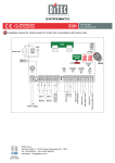
237,21 6:,7&+(6
Four current loop formats are available with this option card and are selected in the following
way:SW1
SW2
SW3
SW4
0.20mA
OFF
OFF
ON
OFF
4-20mA
ON
ON
ON
OFF
20-0mA
OFF
OFF
OFF
ON
20-4mA
ON
ON
OFF
ON
The 0/4-20mA formats will give an increase in speed for an increase in mA.
The 20-4/0mA formats will give an increase in speed for a decrease in mA.
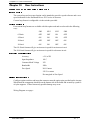
(/(&75,&$/ 63(&,),&$7,21
Accuracy
± 2% of FS
Input Impedance
100 Ω
Common Mode Voltage
30V
Bandwidth
20Hz
Zero Speed
N/O Contact
24V 2A contact
De-energized at Zero Speed
),77,1* ,16758&7,216
Configure option switches and insert the connector onto the option pins provided on the inverter.
When fitted the components should be on the bottom side of the board and secured by a push fit
of nylon supports. If fitted incorrectly possible damage may occur.
Wiring Diagram over page:-
&KDSWHU8VHU,QVWUXFWLRQV
TERMINALS
CONTROL
-
CURRENT SOURCE
BRAKE CONTROL
TRANSDUCER OR
BRAKE CONTROL
+
INVERTER
OPTION 5
SPEED REFERENCE
OPTION 1
SW4
GND
ON
OPTION 2
ON
CURRENT LOOP
OFF
OPTION 3
CURRENT LOOP
OFF
+
OPTION 4
+
ZERO SPEED
OFF
OFF
ON
TRIM
ON
SW3
24V
SW2
OFF
ON
OFF
ON
OFF
ON
OFF
ON
0 to 20mA
4 to 20mA
20 to 0 mA
20 to 4mA
0V REF.
SW1
RAMP OUTPUT
+ 10 V REF.
DIRECTION
DIRECTION
SPEED SETPOINT
RUN
RUN
STOP
&KDSWHU &( (0&5HVSRQVLELOLW\
&KDSWHU
(0&DQGWKH&(0DUN
¶&(· (0& 5(63216,%,/,7<
The subject of CE marking and EMC is explored in more detail in a separate Eurotherm Application
manual entitled ‘EMC Installation Guidelines for modules and systems’, part number HA388879,
available from your local Eurotherm Drives office. The following sections are the minimum necessary
for installation and basic understanding.
Eurotherm Drives are adhering to the CEMEP recommendations on ‘CE’ marking for EMC.
According to SI No. 2372, implementing the EMC directive into UK law, the requirement to CE mark
for EMC, applies only to relevant apparatus that has ‘intrinsic function’ to the end user and which
is placed on the market (supplied). The majority of drive modules/systems sold by Eurotherm Drives
will be incorporated into a higher system/apparatus or machine which includes (at least) the motor,
cable and a driven load before providing intrinsic function to the end user. As such the majority of
Eurotherm Drives products are categorised as components (CEMEP validity field 2) and it would be
incorrect for Eurotherm Drives to apply the CE mark or produce an EC Declaration of Conformity in
respect of EMC. It is the manufacturer/supplier/installer of the relevant apparatus (with the intrinsic
function to the end user) who must demonstrate conformance to the EMC directive
However, in a minority of cases, single drives may have intrinsic function to the end user. An example
is that of ‘add on’ intrinsic function, where an existing fixed speed motor application (such as a fan or
a pump) is converted to variable speed with an add on drive module (CEMEP validity field 1). In this
application Eurotherm Drives CE mark its drive module and issue an EC declaration of conformity.
Because the validity of the ‘CE’ mark for EMC is not known when the product is manufactured, the
‘CE’ mark will be applied via the product manual, and will not be on the product label. From 1997,
when the ‘CE’ mark for the Low Voltage Directive becomes mandatory, the CE mark will appear on
the product label, but its validity for EMC can only be identified from the product manual.
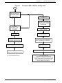
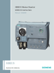
The validity of the ‘CE’ mark can be identified from the flowchart in figure A, refer to SI No. 2372 for
clarification of relevant apparatus.
To assist manufacturers/suppliers/installers of relevant apparatus, Eurotherms 582, 583 and 5831 drive
modules are EMC compliant to EN50081-1 (1992), EN50082-1 (1992), EN50081-2 (1994) and
prEN50082-2 (1992), when fitted with the specified filter and installed according to these instructions,
as confirmed by the manufacturers EMC Declaration to be found at the end of this chapter.
Manufacturers/suppliers/installers of relevant apparatus (CEMEP validity fields 3 & 4) may use this
compliance as a basis for their own justification of overall compliance with the EMC Directive.
It must be clearly understood by the customer before installation commences who is legally responsible
for conformance with the EMC Directive. Misappropriation of the CE mark is a criminal offence.
&KDSWHU &( (0&5HVSRQVLELOLW\
Figure A
Eurotherm EMC ‘CE’ Mark Validity Chart
START
IS E.D. MODULE
RELEVANT APPARATUS
WITH INTRINSIC FUNCTION
TO END USER (CEMEP
VALIDITY FIELD 1)
NO
CEMEP VALIDITY FIELDS
2, 3 AND 4
YES
OPTIONAL E.D. FILTERS
AVAILABLE TO ASSIST USERS
IN CONFORMANCE WITH THE
EMC DIRECTIVE
WILL THE E.D. PRODUCT
BE INSTALLED
ACCORDING TO THE
INSTALLATION
GUIDELINES
NO
EMC CHARACTERISTICS
STATED IN MANUAL
YES
FIT THE SPECIFIED
E.D. EMC FILTER
THE E.D. EC DECLARATION OF
CONFORMITY FOR EMC IS VALID
FOR THE SPECIFIED ED MODULE
EMC INSTALLATION GUIDELINES
STATED IN MANUAL
THE E.D. MANUFACTURERS DECLARATION
FOR EMC IS VALID FOR THE SPECIFIED
MODULE WHEN INSTALLED CORRECTLY
EMC 'CE' MARK CAN BE APPLIED TO E.D.
A GLOBAL EMC SOLUTION
MODULE TO GENERIC EMC STANDARDS:
MAYBE ADVANTAGEOUS
EN50081-1(1992), EN50081-2(1994) AND
NO EMC 'CE'MARK APPLIED TO E.D MODULE
EN50082-1(1992) (AND prEN50082-2(1992)).
E.D. = EUROTHERM DRIVES LIMITED
RELEVANT APPARATUS
MANUFACTURER/SUPPLIER/INSTALLERS
RESPONSIBILITY TO CONFORM WITH EMC DIRECTIVE.
E.D. EMC CHARACTERISTICS AND MANUFACTURERS
DECLARATION MAY BE USED AS A BASIS IN THE
OVERALL PRODCT JUSTIFICATION
&KDSWHU &( (0&5HVSRQVLELOLW\
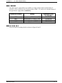
),/7(5 6(/(&7,21
The following AC supply filters are available to comply with the mains terminal limits of
EN55011 (1991) Class B. For the Eurotherm Drives EMC ‘CE’ mark to be valid the fitment of
the specified AC supply filter is mandatory.
(XURWKHUP3URGXFW
5DWLQJ
VLQJOHSKDVHN:N:
VLQJOHSKDVHN:N:
VLQJOHSKDVHN:
VLQJOHSKDVHN:
(XURWKHUP)LOWHU
3DUW1XPEHU
&2
&2
&2
&2
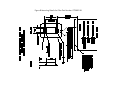
),/7(5 ,167$//$7,21
Filter mechanical mounting details are shown in figures B and C.
)LJXUH%0RXQWLQJ'HWDLOVIRU)LOWHU3DUW1XPEHU&2
)LJXUH&0RXQWLQJ'HWDLOVIRU)LOWHU3DUW1XPEHU&2
&KDSWHU &( (0&5HVSRQVLELOLW\
For both AC and DC drives the conducted emissions increase with motor cable length. EMC
conformance to the stringent limits applied by Eurotherm Drives is only guaranteed up to a
maximum cable length of 5m, but can be increased dependent on reduced limits being applied.
This length can be still further increased by the use of output filters and chokes. Refer to the
separate Eurotherm Application manual entitled ‘EMC Installation Guidelines for modules and
systems’, part number HA388879 for more information
WARNING 1: The AC supply filters produce earth leakage currents in excess of
3.5mA.
WARNING 2: The AC supply filters contain capacitors phase to phase and phase to
earth. Discharge resistors are fitted, but the filters or cabling should not be touched
for a period of 1 minute after the removal of the AC supply.
WARNING 3: The AC supply filter must only be used with a permanent earth
connection. Permanent earthing can be achieved by either a) using a copper
protective earth conductor of at least 10mm2 or b) installing a second conductor in
parallel connection with the protective conductor to a separate protective earth
terminal. The conductor shall on its own meet the requirements for a protective earth
conductor.
WARNING 4: Eurotherm Drives do not recommend the use of RCDs. Special
RCDs (Type B according to the second amendment of IEC755) are required due to
the AC and DC components flowing in the earth leakage current. All loads requiring
protection with the RCD would be at risk.
WARNING 5: Eurotherm Drives only guarantee the thermal performance of the
EMC AC supply filter upto a maximum equivalent cable length of 150m.
:DOO0RXQW
For wall mount applications filters CO389108, CO389110 will require mounting in a separate
suitable enclosure, and all connections made with conduit. In addition the optional 582 gland box
must be used. Ensure the filter to drive cable is passed through conduit mounted between the
filter and the drive gland box. This cable must be as short as possible (0.3m maximum) and
segregated from all other cables.
&XELFOH0RXQW
Ideally the filter will be mounted onto a metallic back panel in the cubicle to which the drive is
mounted too. The RF connection between the drive and filter will be usefully enhanced by
scraping away any paint/insulation between the filter and drive mounting points on the panel.
Liberally apply petroleum jelly over the mounting points and securing threads to prevent
corrosion.
6&5((1,1*
All Eurotherm Drives modules comply with the radiated emission limits of EN55011 (1991)
Class A when installed in free air (Wall Mounted) according to these instructions, using an AC
supply filter and screened motor cable, but using unscreened control and signal cabling. Products
which meet the limits of Class A can be made to meet the more stringent limits of Class B by
simply mounting inside an enclosure with 10dB attenuation between 30 and 100MHz (which
&KDSWHU &( (0&5HVSRQVLELOLW\
would typically be the attenuation provided by a standard metal cubicle) and screening any
control and signal cabling outside of the cubicle (including any optional tacho, encoders or
communications connections etc.).
On AC drives, in addition to screening the motor cable, any connections to the DC link must also
be screened/armoured, with the screen connected at both ends (e.g. to the protective earth of the
dynamic brake resistor).
Safety earthing always takes precedence over EMC earthing.
Screen to earth connections via 360° bonding is 75% more effective than earthing via pigtails.
The integrity of the screen should be maintained over the entire length of the cable. If the cable is
broken to insert contactors, chokes, fuses etc., then the screen must be connected over the
shortest possible distance. Note some hazardous area installations may preclude direct earthing at
both ends of the screen, in this case earth the other end via a 1µF, 50VAC capacitor.
If a shielded cable is not available, lay unshielded motor cables in a metal conduit which will act
as a shield. The conduit must be continuous with a direct electrical contact at both ends. If links
are necessary use braid with a minimum cross sectional area of 10mm2 .
:DOO0RXQW
The cable between the wall mount drive module and the motor must be screened or armoured.
The screen/armour must be earthed at both ends by connecting it to both the motor frame and the
drive in 360° termination's. Ideally these will be via the glanded cable entry to the motor and
drive.
Screening of all the control and signal cables is required to comply with the most stringent
radiated emission limits of EN55011 Class B (including any optional tacho, encoders or
communications connections etc.). The screen integrity should be continuous right back to the
drive. Always minimise the length of screen stripped back to make this connection. The screen
should only be connected at the drive end. If high frequency noise is still a problem, earth at
the non drive end via a 0.1µF capacitor.
&XELFOH0RXQW
The cable between the cubicle and the motor must be screened or armoured. The screen/armour
must be earthed at both ends by connecting it to both the motor frame and the entrance to the
cubicle, ideally in 360° termination's via cable glands. Often the screens are terminated on a
power screen rail at the entrance to the cubicle using ‘U’ clips to achieve a near 360° screen
bond.
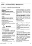
($57+,1*
:DOO0RXQW
A single point earthing policy is to be followed as shown in figure D. The motor protective earth
(PE) connection must run inside the screened cable between the drive and motor. This must be
connected at one end to the motor protective earth terminal and at the other to the drive
protective earth terminal in the cable gland box (Note, only one protective earth conductor is
permitted at each earth terminal contacting point). The filter should be permanently earthed.
Local regulations may dictate the motor protective earth connection is connected locally. This
should be in addition to the protective earth connection made back to the drive module. The RF
impedance of the local motor earth connection will be significantly greater than that via the
screen/armour and will not introduce RF problems.
Safety earthing always takes precedence over EMC earthing.
&KDSWHU &( (0&5HVSRQVLELOLW\
)LJXUH'(0&DQG6DIHW\(DUWKLQJ3ROLF\
AC/DC
AC
Supply
Motor
Motor Cable Screen
Filter
PE
$V VKRUW
DV SRVVLEOH
PE
PE
Safety
Earth
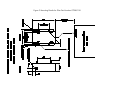
&XELFOH0RXQW
Reference should be made to EN60204 regarding earthing for cubicles. In addition, when more
than one electrical product is fitted inside a cubicle care must be taken to ensure that noise
flowing in the earth connection does not couple into other equipment. A star point earthing
policy is strongly recommended separating noisy from quiet earths. Six earths can be identified
as shown in figure E. The screens are terminated on the separate screen rails at the entrance to the
cubicle using ‘U’ clips to achieve a near 360° screen bond.
Safety earthing always takes precedence over EMC earthing.
Refer to the separate Eurotherm Application manual entitled ‘EMC Installation Guidelines for
modules and systems’, part number HA388879 for more information
)LJXUH(&XELFOH(DUWKLQJ3ROLF\
To Motor
To Motor
Screened
To Motor
Screened
PE = protective earth
OA = analogue 0volts
OD = digital 0volts
Power Screen Earth
PLC
AC/DC
AC/DC
AC/DC
PE
0D
Unscreened
Signals
PE
0A
0D
PE
0A
0D
PE
0A
0D
Unscreened
Signals
24V
Control
Analogue Clean Earth
Dirty Earth
Incoming Safety Earth
Digital Clean Earth
Metal Work Earth
STAR POINT
Metal
Work
Backplate
110V
Control
Doors
&KDSWHU &( (0&5HVSRQVLELOLW\
(0& 7(&+1,&$/ 63(&,),&$7,21
7DEOH+0LQLPXP(0&,PPXQLW\3HUIRUPDQFHZKHQLQVWDOOHGDVUHFRPPHQGHG
3RUW
3KHQRPHQRQ
7HVW
6WDQGDUG
/HYHO
&ULWHULRQ
*HQHULF
6WDQGDUG
(QFORVXUH
(6'
,(&
N9$'
6HOI5HFRYHU\ (1
3RUW
5))LHOG4 ,(& 9PN+]$0 1R&KDQJH
3RZHU
)DVW7UDQVLHQW ,(&
N9
6HOI5HFRYHU\
3RUWV
%XUVW
'UDIW
6LJQDO )DVW7UDQVLHQW ,(&
N9
6HOI5HFRYHU\ SU(1
&RQWURO
%XUVW
3RZHU
)DVW7UDQVLHQW ,(&
N9
6HOI5HFRYHU\
,QWHUIDFHV
%XUVW
2QO\IRUZDOOPRXQWSURGXFW
7DEOH,0D[LPXP(PLVVLRQ3HUIRUPDQFHIRU¶&(·PDUNHGSURGXFWZLWKVSHFLILHGILOWHUVLQVWDOOHG
DVUHFRPPHQGHG
3RUW
(QFORVXUH3RUW
3RZHU3RUW
3KHQRPHQRQ
7HVW6WDQGDUG
/HYHO
5DGLDWHG
(1
&ODVV%
&RQGXFWHG
(1
&ODVV%
* Achieved with up to 5m of motor cable.
*HQHULF6WDQGDUG
(1
(1
The AC supply filters may be flash tested in circuit upto 2000V DC for 1 minute. Ensure all
AC/DC drives and other equipment that may be damaged by such flash testing has been suitably
isolated/removed/short circuited as applicable. Due to the internal capacitors between phase and
earth, the DC voltage should be wound up slowly, to prevent excessive earth current. For similar
reasons AC flash testing cannot be performed due to the excessive earth leakage current.
Repeated flash testing on such units is not recommended as it may degrade the insulation.
&KDSWHU &( (0&5HVSRQVLELOLW\
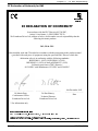
(&'HFODUDWLRQRI&RQIRUPLW\IRU(0&
(8527+(50
'5,9(6
(&'(&/$5$7,212)&21)250,7<
In accordance with the EEC Directive 89/336/EEC,
Articte 10 and Annex 1, (EMC DIRECTIVE)
We Eurotherm Drives Ltd, address as below, declare under our sole responsibility that the
following electronic products
582, 583 & 5831
when installed, used and CE marked in accordance with the instructions in the product manual
(provided with each piece of equipment) using the specified EMC filters to which this
declaration refers is in conformity with the following standards:BSEN50081-1 (1992), BS EN50081-2 (1994)
BSEN50082-1 (1992) & draft prEN50082-2* (1992)
Following provisions of EEC-Directive
89/336/EEC with amendments 92/31/EEC and 93/68/EEC
.................................................
Dr Martin Payn,
Conformance Officer
Eurotherm Drives Ltd
...................................................
Dr Dan Slattery,
Technical Director
Eurotherm Drives Ltd
8th December 1995
......................................
Date
* For information only
(8527+(50 '5,9(6 /,0,7('
1(: &2857:,&. /$1( /,77/(+$03721 :(67 6866(; %1 3'
7(/(3+21( )$; 5HJLVWHUHG QXPEHU (QJODQG 5HJLVWHUHG 2IILFH /HRQDUGVOHH /RZHU %HHGLQJ +RUVKDP :HVW 6XVVH[ 5+ 33
&KDSWHU &( (0&5HVSRQVLELOLW\
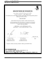
0DQXIDFWXUHUV(0&'HFODUDWLRQ
(8527+(50
'5,9(6
0$18)$&785(56(0&'(&/$5$7,21
In accordance with the EEC Directive 89/336/EEC,
Article 10 and Annex 1, (EMC DIRECTIVE)
We Eurotherm Drives Ltd, address as below, declare under our sole responsibility that the
following electronic products
582, 583 & 5831
when installed and used in accordance with the instructions in the
product manual (provided with each piece of equipment) and using the
specified EMC filters to which this declaration refers is in conformity
with the following standards:BSEN50081-1 (1992), BSEN50081-2 (1994)
BSEN50082-1# (1992) & draft prEN50082-2# (1992)
.................................................
Dr Martin Payn,
Conformance Officer
Eurotherm Drives Ltd
#
...................................................
Dr Dan Slattery,
Technical Director
Eurotherm Drives Ltd
29th April 1996
......................................
Date
Compliant with these immunity standards without specified EMC filters
(8527+(50 '5,9(6 /,0,7('
1(: &2857:,&. /$1( /,77/(+$03721 :(67 6866(; %1 3'
7(/(3+21( )$; 5HJLVWHUHG QXPEHU (QJODQG 5HJLVWHUHG 2IILFH /HRQDUGVOHH /RZHU %HHGLQJ +RUVKDP :HVW 6XVVH[ 5+ 33