1
ECS 3M
USER’S MANUAL
uwvyx
´ µ¶ · ¸ p q
¯°±² ³
no
® ¬
bh c i d j e k f l g m
ǻ
¦ § ¨
©
EPaXUP]
!#"$&%!' (&)* *"$&+ ' , -/. (
0
VW
12
1
7
6
11
10
9
_` a
8
B
z
{
|
}
S
T
U
U
2
3 C DE F G H H I
OP
4
J Q KR L M N
5
;=</>!?*@!A
_` a
X YZ [ \ ] ] ^ r ¡ st¢ t £ ¤ ¥
~
1325476 8:9
Page 1
ECS-3M
Although the manufacturer has made every effort
to ensure the accuracy of the information
contained herein, this document is subject to
change without notice due to ongoing product
development.
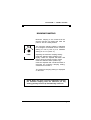
WARNINGS AND PRECAUTIONS
Equipment, probe failure, blown fuses and/or
tripped breakers may prove harmful to the
contents of the building. Therefore it is strongly
recommended to install backup devices and alarm
or warning devices. Spare equipment should also
be available at the owner’s site. Equipment
manufactured by the manufacturer is protected
against normal line surges. High surges caused by
thunder storms or power supply equipment may
damage this equipment. For added security
against line voltage surges it is recommended that
surge and noise suppression devices be installed
at the electrical distribution panel. Use of shielded
cable for probes is recommended for protection
against lightning. These devices are available from
most electrical supply distributors.
RECOMMENDATIONS
The manufacturer recommends that all installation
procedures described herein be performed by a
qualified electrician or installation technician.
Further more the manufacturer recommends to
test all the functions and equipment connected to
the ECS, including the alarm system and backup
devices, after installation, after changes to the
installation and every month after that.
Fuse verification and replacement, as well as the
proper setting of control values shall be the
responsibility of the owner of this equipment.
Page 2
TABLE OF CONTENTS
CHAPTER 1 - INTRODUCTION
1.
1.1
General ........................................................................... 5
Description ....................................................................... 5
Definition of terms ......................................................................... 7
CHAPTER 2 - INSTALLATION
2.1
2.2
2.3
2.3.1
2.3.2
2.4
2.4.1
2.4.1.1
2.4.1.2
2.4.2
2.4.3
2.4.4
2.5
2.5.1
2.5.2
2.5.3
2.6
2.7
Unpacking ........................................................................ 9
Mounting ........................................................................ 10
Switch Settings ............................................................... 10
Line Voltage Selector Switch .......................................... 10
Software Settings Switch ................................................ 11
Connection Procedure .................................................... 11
Input Power ..................................................................... 11
115 VAC.......................................................................... 11
230 VAC.......................................................................... 12
Fan 1 ............................................................................... 12
Fan 2 ............................................................................... 12
Fan 3/ Heater .................................................................. 12
Temperature/Humidity Probes ........................................ 12
Single Temperature Probe.............................................. 13
Averaging ........................................................................ 13
Humidity Probe ............................................................... 13
Alarm ............................................................................... 13
Powering Up ................................................................... 14
CHAPTER 3 - USER GUIDE
LED Status Window ........................................................ 20
Control Dials ................................................................... 20
PRIMARY FUNCTIONS
Main Set Point Temperature ........................................... 23
Fan 1 Differential ............................................................ 24
Fan 1 Minimum Speed .................................................... 25
Fan 1 Duty Cycle ............................................................ 26
Fan 2 Relative Set Point ................................................ 27
Fan 2 Differential ............................................................ 28
Fan 2 Minimum Speed .................................................... 29
Heater/Fan 3 Relative Set Point ..................................... 30
Page 3
ECS-3M
CONTENTS CONTINUED...
Reduction per day ........................................................... 31
Record Low Temperature 3
2
Record High Temperature ............................................. 33
Room Temperature ........................................................ 34
SECONDARY FUNCTIONS
Relative Humidity Set Point ............................................ 35
Fan 1 Motor ..................................................................... 36
Fan 1 Minimum Humidity Speed ..................................... 37
Fan 1 Duty Cycle Period ................................................. 38
Fan 2 Motor ..................................................................... 39
Heater/Fan 3 Differential ................................................. 40
Minimum Ramping .......................................................... 41
Low Temperature Alarm ................................................. 42
High Temperature Alarm ................................................. 43
Relative Humidity Display ............................................... 44
APPENDIX
Motor Compatibility Table ............................................................ 47
Troubleshooting ........................................................................... 48
Specification ................................................................................. 49
Record Form ................................................................................ 50
Page 4
CHAPTER 1 - INTRODUCTION
1. GENERAL
This document provides a description of the ECS-3M
control panel. It is organized as follows:
• Introduction
• Installation
• User’s Guide
• Appendix
1.1 DESCRIPTION
Congratulations on the purchase of your ECS-3M
environmental control system. The ECS-M product line
provides you with full control over temperature, humidity,
air flow, and heat, resulting in a comfortable environment
for your livestock.
The ECS-M product line offers a number of added features
over existing ECS controls, such as:
•
•
•
•
•
•
Compatibility with DIP-1 control.
Hi/Lo temperature indication.
Automatic temperature reduction (ramping).
Adaptable variable speed outputs for a wide selection
of fan model types.
Humidity probe.
Full torque fan start to prevent motor damage.
The ECS-3M provides microprocessor control over a three
stage output.
The first stage controls a variable speed fan which can
operate at a continuous low speed to ensure good quality
of air when room temperature is below the main set point.
In addition, the first stage may be programmed to cycle
ON and OFF. When room temperature rises above the
main set point, the fan accelerates to increase the airflow.
Page 5
ECS-3M
DESCRIPTION CONTINUED...
The second stage provides control over a second variable
speed fan to help the first fan when higher room temperatures
require increased airflow. This second stage is also fully
programmable for settings, such as minimum speed, relative
set point, etc.
The third stage controls either a heater for colder climates, or
a third fan where additional cooling is required.
The ECS-3M provides you with full control over all three
stages via the use of an easy to follow display panel. All
programmable features can be customized to meet your
requirements. The ECS-3M keeps you constantly informed by
displaying the status of all of its outputs as well as the room
temperature. With an optional humidity probe, the ECS-3M
displays current humidity levels.
Safety of livestock is ensured by the continuous control of
climate and timely alarm notification, should environmental
conditions exceed alarm set points. Further security may be
obtained by connecting all ECS controls in a network
configuration to a computer via the use of an optional RCM40 remote monitoring unit . This provides remote control
monitoring of each room. All control panel variable outputs
are fused, and all programmable settings are maintained,
whether the ECS-3M is powered or not.
The ECS-3M provides an automatic constant temperature
reduction (ramping) feature for your maturing livestock. A
built-in low temperature safety factor prevents temperatures
from reaching dangerous limits.
With an ECS-3M in control of your climate, you are assured of
optimal living conditions for your livestock.
Page 6
DEFINITION OF TERMS
DEFINITION OF TERMS
MAIN SET POINT
The desired room temperature. Other temperature
settings on the ECS-3M are relative to the main set
point temperature.
RELATIVE TEMPERATURE
A value added to, or subtracted from the main set
point, which results in a new temperature at which a
desired action starts or stops.
ROOM TEMPERATURE
The actual temperature in a closed area.
ROOM HUMIDITY
The actual humidity level of a closed area.
MINIMUM FAN SPEED
The desired minimum speed for variable speed fans.
RAMPING
An automatic daily reduction in the main set point and
all temperature settings relative to this.
DIFFERENTIAL
ON/OFF (relay). Range of temperature where two
conditions are possible. The output depends on
whether the temperature was increasing or decreasing
when it enters that range.
VARIABLE. (Bandwidth) Temperature range where a
variable fan speed fan accelerates, as the
temperature increases. Minimum value at relative set
point and 100% at relative set point + Bandwidth.
Page 7
ECS-3M
Page 8
CHAPTER 2 - INSTALLATION
Chapter 2 describes the installation of the ECS-3M
control panel.
The manufacturer recommends that the following
instructions be adhered to as closely as possible,
and that all work be performed by a certified
electrician. Failure to do so may void the warranty!
2.1 UNPACKING
Unpack the ECS-3M and inspect contents for damage.
Should the contents appear to be damaged, contact
your local distributor for return procedures.
The package should contain the following standard
items:
• 1 ECS-3M control.
• 1 installed temperature probe (model number 20041K).
• 3 cable fasteners or fuses.
• 1 Instruction manual.
The following optional items may be added:
•
•
3 additional temperature probes for temperature
averaging,
1 humidity probe. The ECS-3M requires the RHT-1
humidity probe for maximum accuracy of monitoring
and control of humidity levels.
Page 9
ECS-3M
2.2 MOUNTING
Use a screwdriver to remove the faceplate and the plate
on the power compartment.
To limit the unit’s exposure to noxious gases, install the
unit in a hallway.
Make sure the unit is mounted right side up with the
cable entry holes facing down.
The ECS-3M operates in a temperature range of 32° F 120 ° F (0 ° C- 50 ° C).
The enclosure is watertight, it is not splash proof or
immersion proof. DO NOT WATER the control. Cover it
carefully with plastic when cleaning the room.
* It is prohibited to use overhead cables outside the building.
Once both faceplates are off, install the mounting screw
on the wall and install the unit on it. Use two more screws
to secure the ECS-3M in place using the bottom mounting
holes.
Mounting hardware is not shipped with the unit.
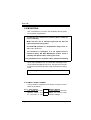
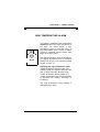
2.3 SWITCH SETTINGS
The ECS-3M is configured for a variety of options via two
switches as follows:
2.3.1 - Line Voltage
230V Selector Switch
This switch is located
on the surface of the main
(bottom) board and 115V adapts the control panel
for 115 VAC or 230
VAC line voltage.
Page 10
CHAPTER 2 - INSTALLATION
2.3.2 - Software Settings Switch
This switch is located at the rear of the control panel
faceplate and adjusts the following options.
OFF
ON
OFF
1
2
3
4
Fahrenheit
Settings locked
Stage 3 = Heat
Not used
ON
Celsius
Setting unlocked
Stage 3 = Fan
Relative Humidity
Switch 1
Selects the Fahrenheit
display for the front panel.
or
Celsius
Switch 2
Locks/unlocks user settings. All settings except
for main set point, record low, and record high
are locked when this switch is OFF.
Switch 3
Selects between a Heater or Fan control on
stage three of the control panel.
Switch 4
With or without a humidity probe, DIP switch #4
must be ON.
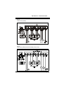
2.4 CONNECTION PROCEDURE
For connection procedures which follow see figures 1 to 3.
2.4.1 - Input power
Use a screwdriver to remove cable knock-outs for cabling
installation to the control panel.
2.4.1.1 - 115 VAC
Do not apply power to the control panel until all
connections have been completed!
Make certain that the line voltage selector switch is set
to 115 VAC. Connect the power cable to terminals 7 and 8
on the main (bottom) board and connect the ground wire to
terminal 9 on the main board .
Page 11
ECS-3M
2.4.1.2 - 230 VAC
Make certain that the line voltage selector switch is
set to 230 VAC. Connect the power cable to terminals 7
and 8 on the main (bottom) board and connect the ground
wire to terminal 9 on the main board.
2.4.2 - Fan 1 (terminals 5 and 6)
Stage 1 of the ECS-3M controls the operation of the
primary fan. Connect the two leads from fan 1 to terminals
5 and 6 on the main (bottom) board.
2.4.3 - Fan 2 (terminals 3 and 4)
Stage 2 of the ECS-3M controls the operation of the
secondary fan. Connect the two leads from fan 2 to
terminals 3 and 4 on the main (bottom) board.
2.4.4 - Fan 3/Heater (terminals 1 and 2)
Stage 3 of the ECS-3M provides a dry contact closure
which controls the operation of a third fixed speed fan or a
heater. This contact closure is voltage rated to 230 VAC.
The current rating of the dry contact is 10 Amps (resistive)
for a heater and 6 Amps (inductive) for a fan. Set the
software settings DIP switch at the rear of the control
panel faceplate to ON for a fan or OFF for a heater.
Connect the heater or fan 3 to terminals 1 and 2 on the
main (bottom) board.
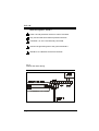
2.5 TEMPERATURE / HUMIDITY PROBES
Temperature and humidity probes use a “Class 2” low
voltage circuit. These cables can be extended to a
distance of 150 meters (500 feet). Single probe
temperature and humidity connections are illustrated in
figure 4, while temperature probe averaging connections
are illustrated in figure 5.
Page 12
CHAPTER 2 - INSTALLATION
Use shielded cabling for probes . Connect the shields
to the “SHLD” terminal. Failure to do so may result in
inaccurate readings!
2.5.1 Single Temperature Probe
Install a single temperature probe in the area that best
reflects the overall room temperature. Connect the two
leads and the shield of the temperature probe to the
control panel terminals labeled “Probe”, as indicated in
figure 4.
2.5.2 Averaging (optional)
Four temperature probes are required if temperature
averaging is desired in larger rooms. Place the probes in
appropriate locations to best average room temperature.
Refer to figure 5.
2.5.3 Humidity Probe (optional)
Install one humidity probe in the area that best reflects the
overall room humidity. Connect the humidity probe to the
control panel terminals labeled “Probe”, as indicated in
figure 4.
2.6 ALARM
The ECS-3M provides a normally open and normally
closed dry contact for alarming low or high temperature
conditions. In addition, this same contact can be used to
signal a power failure. This contact may be connected to
an alarm system, or directly to a siren and/or auto-dialer.
Make normally open or normally closed connections as
indicated in figure 4.
Momentary power interruptions may trigger false
alarms! To avoid them, when the ECS-3M is connected
to an alarm system, install a time delay relay between
Page 13
ECS-3M
2.7 POWERING UP
Before powering up the ECS-3M, install the faceplate to
the control’s enclosure using the six screws previously
removed.
Set Selector knob to position (12).
Upon power up, the unit will test its display by briefly
lighting all the segments of its LED. Make certain that
all segments light up.
Following the LED display test, the unit displays the
room temperature.
If the temperature does not appear, refer to the
Troubleshooting section in the appendix of this
document.
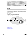
Fig. 1
Two Fans (115V) and One Heating Unit (115V)
Page 14
CHAPTER 2 - INSTALLATION
Fig. 2
Three Fans (230V)
Fig. 3
Two Fans (230V) and One Heating Unit (115V)
Page 15
ECS-3M
Notes for Figures 1, 2 and 3
1
Power cut and protection devices in case of overload.
2
Only use fans that have thermal protection devices.
3
Terminals 4, 6, and 7 are internally connected.
44
Connect the grounding wire to the ground terminal 9 .
5
Should be on a different circuit from the ECS.
Fig. 4.
Probes and Alarm Wiring
Page 16
CHAPTER 2 - INSTALLATION
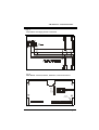
Fig. 5
Temperature Averaging Probe Connection
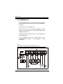
1 0A S lo -B lo
F an 1
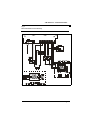
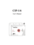
Fig. 6
Main Board: Terminal, Blocks, Switches, Fuses and Ground
1 0A S lo -B lo
F an 2
Grou nd
Connection
Probes
IPM-1
Alarm
1 046
Page 17
ECS-3M
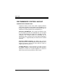
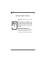
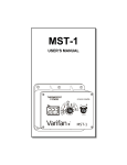
RECOMMENDED CONTROL BACKUP
WARNING AND PRECAUTIONS
Equipment failure, blown fuses and/or tripped breakers
may prove harmful to the content of the building. It is
therefore strongly recommended to install backup devices
and alarm or warning devices (see example fig. 7).
BACKUP THERMOSTAT. If the control is defective, then
the thermostat will start the dedicated fan at full speed
when the temperature will reach the T15-WD set value.
Therefore, the T15-WD should be accessible for its
adjustment and it should be set at the same temperature
as the alarm, i.e. approximately 5º C above the fan relative
set point.
BACKUP POWER SOURCE. The DPDT relay connects
to the source 1 in normal operation but will switch to the
source 2 if source 1 is off. The relay shall be chosen to
support the load connect to it.
ALARM CIRCUIT. In normal operation, the alarm circuit of
the Varifan control is a short circuit. But if the control is
defective or if there is no power applied to it, then the
alarm circuit of the control will be an open circuit.
Page 18
CHAPTER 2 - INSTALLATION
Fig 7.
Recommended control backup
Page 19
ECS-3M
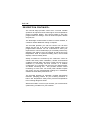
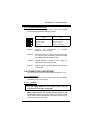
CHAPTER 3 - USER’S GUIDE
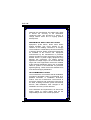
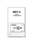
The ECS-3M front panel shown previously features a
LED status window and two control dials which are used
respectively to select a function and adjust a setting.
LED STATUS WINDOW
The LED status window features a 3 digit LED readout for
the display of temperature in Fahrenheit or Celsius,
humidity level, and programmable settings.
In addition, the LED status window displays the
operational status of Fans 1, 2, and Fan 3 or a heater via
four additional LEDS (shown above in LED window).
When ON, each LED indicates that its associated fan or
heater is operating. The fourth LED lights up to indicate a
low or high temperature alarm condition.
CONTROL DIALS
The center dial is the Selector dial and is used to select
one of the control panel’s 12 primary or 10 secondary
functions. The dial located to the right of the Selector dial
is the Adjuster dial and is used to enter secondary
function mode and to adjust the setting of each function.
Page 20
CHAPTER 3 - USER’S GUIDE
Page 21
ECS-3M
The 12 primary functions are:
• 1 Main set point temperature
• 2 Fan 1 modulation band
• 3 Fan 1 minimum speed
• 4 Fan 1 duty cycle timer
• 5 Fan 2 relative set point temperature
• 6 Fan 2 modulation band
• 7 Fan 2 minimum speed
• 8 Fan 3 Heater/fan relative temperature set point
• 9 Reduction per day
• 10 Record low temperature display
• 11 Record high temperature display
• 12 Room temperature display
Any one of these functions is selected by rotating the Selector dial
to the corresponding number and associated graphical image
printed on the faceplate of the panel. When primary functions 1
through 11 are selected, the LED status window displays a
blinking value. Function 12 displays ambient temperature.
The 10 secondary functions are:
• 1 Relative humidity set point
• 2 Fan 1 motor compatibility
• 3 Fan 1 minimum speed setting for humidity
• 4 Fan 1 duty cycle period
• 6 Fan 2 motor compatibility
• 8 Fan 3 Heater/fan differential
• 9 Ramping minimum temperature limit
• 10 Low temperature alarm
• 11 High temperature alarm
• 12 Relative humidity display
Select any one of these secondary mode functions by:
rotating the selector dial to (12)
Then rotate the adjuster dial back and forth to enter secondary
mode.
Then rotate the selector dial from function (12) to any other
function.
When secondary functions 1 through 4, 6, and 8 through 11 are
selected the status window displays a flashing value along with a
scrolling LED display. Selection of function 12 takes the ECS back
to primary mode.
Page 22
CHAPTER 3 - USER’S GUIDE
PRIMARY FUNCTIONS
MAIN SET POINT
1
The main set point establishes the target
temperature in the building. This value is
used as the reference point for other settings.
The main set point temperature is adjusted in
0.5 degree increments from a minimum
setting of -9.5° C (13.5° F) to a maximum
setting of 41.0° C (105.0° F).
Adjusting the main set point temperature:
•rotate the Selector dial to position (1),
•rotate the Adjuster dial counterclockwise to
decrease the temperature setting, clockwise
to increase it.
The main set point temperature is displayed on
the ECS.
Note: The reduction per day feature
(primary function 9) must be (OFF) to
Page 23
ECS-3M
FAN 1 DIFFERENTIAL
The Fan 1 differential setting establishes the
temperature at which Fan 1 reaches maximum
speed. The value is a temperature difference
from the main set point.
2
The Fan 1 differential is adjusted in 0.5 degree
increments from a minimum setting of 2.0° F
(1.0° C) to a maximum setting of 18.0° F (10.0°
C).
Adjusting the Fan 1 differential:
• rotate the Selector dial to position (2),
• rotate the adjustment dial counterclockwise
to decrease the temperature setting,
clockwise to increase it.
The Fan 1 Differential setting is displayed on
the ECS.
Example: A main set point
temperature of 70° F along with a
Fan 1 differential setting of 5° F is
set. When the temperature of the
room reaches 75° F, Fan 1
operates at its maximum speed.
Page 24
CHAPTER 3 - USER’S GUIDE
FAN 1 MINIMUM SPEED
3
This function sets the minimum speed of Fan
1 when room temperature is below the main
set point. This value is entered as a
percentage of a fan’s maximum speed. The
Fan 1 minimum speed is adjusted in 2%
increments from a minimum setting of 12% to
a maximum setting of 100%.
Adjusting the minimum speed of Fan 1:
•rotate the Selector dial to position (3),
•rotate the Adjuster dial counterclockwise to
decrease fan speed, clockwise to increase it.
The minimum fan speed is displayed on the ECS.
NOTE: Upon start-up, Fan 1 will run at
its maximum speed for 4 seconds.
This feature helps to minimize the
risks of jams caused by ice.
Page 25
ECS-3M
FAN 1 DUTY CYCLE
4
As long as the actual temperature is below the
main set point, Fan 1 operates at the minimum
speed set by Fan 1 Minimum Speed (primary
function 3). The Fan 1 duty cycle sets the percentage of time the fan is ON versus the
percentage of time the fan is OFF. The ON
time is entered as a percentage of the total
time which is known as the period.
The Fan 1 duty cycle is adjusted in 5%
increments from a minimum setting of OFF,
5%, 10% etc., up to a maximum setting of ON
corresponding to continuous operation.
Adjusting the duty cycle of Fan 1:
• rotate the Selector dial to position (4),
• rotate the Adjuster dial counterclockwise
to decrease the duty cycle, clockwise to
increase it.
The duty cycle is displayed on the ECS.
Example: The period of Fan 1 is set to 8 minutes by secondary function (4), while the duty
cycle is set to 50%. As long as the main set
point temperature of the room has not been
reached, the fan operates at a minimum speed
for 4 minutes, and OFF for 4 minutes.
Page 26
CHAPTER 3 - USER’S GUIDE
FAN 2 RELATIVE SET POINT
5
The Fan 2 relative set point establishes the
temperature above the main set point at which
Fan 2 begins to operate at its minimum speed.
The value is a temperature difference from
the main set point.
The Fan 2 relative set point is adjusted in 0.5
degree increments from a minimum setting of
0.0° C (0.0° F) to a maximum setting of 10.0° C
(18.0° F).
Adjusting the relative set point of Fan 2:
•rotate the selector dial to position (5),
•rotate the adjuster dial counterclockwise to
decrease the relative set point, clockwise to
increase it.
The Fan 2 relative set point is displayed on the
ECS.
Example: A main set point of 22° C along
with a Fan 2 relative set point of 5° C is
selected. When room temperature reaches
27° C Fan 2 begins to operate at minimum
speed.
Page 27
ECS-3M
FAN 2 DIFFERENTIAL
The Fan 2 differential setting is the
temperature at which Fan 2 reaches maximum
speed. The value entered is the temperature
difference above the Fan 2 relative set point
temperature setting.
The Fan 2 differential is adjusted in 0.5 degree
increments from a minimum setting of 2.0° F
(1.0° C) to a maximum setting of 18.0° F (10.0°
C).
Adjusting the Fan 2 differential:
• rotate the Selector dial to position (6),
• rotate the Adjuster dial counterclockwise
to decrease the Fan 2 differential setting,
clockwise to increase it.
The Fan 2 differential setting is displayed on
the ECS.
Example: The main set point temperature
of the room is 70° F. A Fan 2 relative set
point of 5° F along with a Fan 2 differential
setting of 5° F is set. When the
temperature of the room reaches 80° F
Fan 2 operates at its maximum speed.
Page 28
CHAPTER 3 - USER’S GUIDE
FAN 2 MINIMUM SPEED
When room temperature is at the Fan 2
relative set point, Fan 2 runs at minimum
speed set by this function. This value is
entered as a percentage of fan maximum
speed. The Fan 2 minimum speed is adjusted
in 2% increments from a minimum setting of
12% to a maximum setting of 100%.
Adjusting the minimum speed of Fan 2:
• rotate the selector dial to position (7),
• rotate the adjuster dial counterclockwise to
decrease fan speed, clockwise to increase
it.
The minimum fan speed is displayed on the
ECS.
NOTE: Upon start-up, Fan 2 will run
at maximum speed for 4 seconds.
This feature helps to minimize the
risks of jams caused by ice.
Page 29
ECS-3M
HEATER/FAN 3 RELATIVE SET POINT
The Heater/Fan 3 relative set point is the
relative temperature at which Heater/Fan 3
begins to operate. This value is the temperature
difference from the main set point.
When a heater is connected,the relative set
point is below the main set point. When a fan is
connected, the relative set point is above the
main set point.
The Heater/Fan 3 relative set point temperature
is adjusted in 0.5 degree increments from a
minimum setting of -5.0° C (-9.0° F) to a
maximum setting of 10.0° C (18.0° F).
Adjusting the Heater/Fan 3 relative set point:
•rotate the selector dial to position (8),
•rotate the adjuster dial counterclockwise to
decrease the temperature setting, clockwise to
increase it.
•The relative temperature setting is displayed on
the ECS.
The relative temperature setting is displayed on
the ECS
Example: The main set point temperature is adjusted
to 70° F. A heater is in use and the relative set point is
adjusted to -5° F. When the room temperature reaches
65° F the heater begins to operate.
A third fan is in use and the relative set point is
adjusted to 15° F. When the room temperature reaches
85° F the third fan begins to run.
Page 30
CHAPTER 3 - USER’S GUIDE
REDUCTION PER DAY
The reduction per day (ramping) function
automatically reduces the main set point by
the set value every 24 hours.
The reduction setting is adjusted in 0.01
degree decrements from a minimum setting
of OFF, -0.01° C (-0.01° F) to a maximum
setting of -0.50° C (-0.99° F).
The main set point must be greater than
the minimum ramping.
Adjusting the reduction per day:
•rotate the selector dial to position (9),
•rotate the adjuster dial counterclockwise to
decrease the reduction value, clockwise to
increase it.
The reduction setting is displayed on the ECS.
NOTE: When ramping is activated or enabled, the main
set point temperature cannot be manually adjusted.
Ramping automatically turns OFF when the minimum
temperature limit is reached!
Example: The main set point temperature is set to 70° F
and ramping is adjusted to -0.05° F. The following day the
main set point temperature drops to 69.95° F followed by
69.90° F on the next. Although the main set point real
value decreases, the display will be changed after 10
days. The main set point will then be 69.5° F.
Page 31
ECS-3M
RECORD LOW TEMPERATURE
This function displays the lowest recorded
temperature since the last clear.
The record low temperature is rounded to the
nearest 0.5 degree from a minimum display
of -10.0° C (13.5° F) to a maximum display of
40.5° C (105.0° F). If a temperature lower
than -10° C is recorded, Lo is displayed.
Displaying the lowest temperature
recorded:
•rotate the selector dial to position (10)
Clearing the low temperature value
•quick ly rotate the
adjuster
counterclockwise, then clockwise.
CLr will be briefly displayed on the ECS.
Page 32
dial
CHAPTER 3 - USER’S GUIDE
RECORD HIGH TEMPERATURE
This function displays the highest recorded
temperature since the last clear.
The record high temperature is rounded up to
the nearest 0.5 degree from a minimum
display of -10.0° C (13.5° F) to a maximum
display of 40.5° C (105.0° F). If a temperature
higher than 40.5° C is recorded, Hi is
displayed.
Displaying the highest temperature
recorded:
•rotate the selector dial to position (11)
Clearing the high temperature value
•quick ly rotate
the
adjuster
counterclockwise, then clockwise.
dial
CLr will be briefly displayed on the ECS.
Page 33
ECS-3M
ROOM TEMPERATURE
This function displays the room
temperature. The Selector dial should
normally be left in this position.
12
Room temperature is displayed to the
nearest 0.5 degree from a minimum display
of -10.0° C (13.5° F) to a maximum display
of 41.0° C (105.0° F). If the temperature is
lower than -10.0° C, Lo is displayed. If the
temperature is higher than 41.0° C, Hi is
displayed.
Viewing the room temperature:
•rotate the selector dial to position (12)
Room temperature is displayed on the ECS.
Page 34
CHAPTER 3 - USER’S GUIDE
SECONDARY FUNCTIONS
RELATIVE HUMIDITY SET POINT
RH
This setting regulates room humidity only
when a humidity sensor is connected to the
ECS. The humidity setting affects Fan 1 only.
When humidity in the room exceeds the
relative humidity set point, Fan 1 minimum
speed increases gradually and proportionally.
If relative humidity rises in the 10% range
above the humidity set point, minimum speed
also increases proportionally up to the value
set by secondary function (3). The humidity
level is adjusted in 1% increments from a
minimum setting of 30% to a maximum setting
of 80%.
Adjusting the relative humidity level:
•rotate the selector dial to position (12),
•rapidly rotate the adjuster dial back and forth
to enter secondary function mode,
•rotate the selector dial to position (1),
•rotate the adjuster dial counterclockwise to
decrease the humidity set point, clockwise to
increase it.
The humidity setting is displayed on the ECS.
Page 35
ECS-3M
FAN 1 MOTOR
Motor
The Fan 1 motor compatibility setting adjusts
the ECS-3M outputs to the electrical
characteristics of the fan motor. Eight
choices are available. Choice 1 is suitable for
most fans. If your motor is not listed in the
compatibility table in the Appendix, try all
choices and take the one that offers the best
performance. Settings 2 - 8 are the optimized
settings for fan models listed in the
compatibility table. Using the compatibility
table, find the model number of your fan
motor and take note of the fan motor
compatibility number.
Setting the Fan 1 motor compatibility:
• rotate the Selector dial to position (12),
• rapidly rotate the Adjuster dial back and forth
to enter secondary function mode,
• rotate the Selector dial to position (2),
• rotate the Adjuster dial to select a motor
curve.
The Fan 1 motor compatibility setting is
displayed on the ECS.
Page 36
CHAPTER 3 - USER’S GUIDE
FAN 1 MINIMUM SPEED FOR HUMIDITY
This function establishes the minimum speed
of Fan 1 when the relative humidity level of
the room exceeds the relative humidity set
point. The speed setting for humidity must be
set higher than the speed setting for
temperature. This value is entered as a
percentage of maximum speed.
Humidity
The Fan 1 minimum speed is adjusted in 2%
increments from a minimum setting of 12% to
a maximum setting of 100%.
Adjusting the Fan 1 minimum speed for
humidity:
•rotate the Selector dial to position (12),
•rapidly rotate the Adjuster dial back and
forth to enter secondary function mode,
•rotate the Selector dial to position (3),
•rotate the Adjuster dial counterclockwise to
decrease the speed, clockwise to increase it.
The Fan 1 minimum speed setting for
humidity is displayed on the ECS.
Example: The relative humidity setting is adjusted to
65%, Fan 1 minimum speed to 25%, and Fan 1
minimum speed for humidity to 50%.
When the humidity level of the room reaches 65% the
minimum speed of Fan 1 gradually increases to
reaches 50% when the humidity level of the room is
75%.
Page 37
ECS-3M
FAN 1 DUTY CYCLE PERIOD
The Fan 1 duty cycle period is adjusted in
conjunction with the Fan 1 duty cycle timer
(primary function 4). The Fan 1 duty cycle
period is the total time in ON-OFF fan cycle.
The period is adjusted in 1 minute
increments from a setting of 1 minute to a
maximum setting of 10 minutes.
Period
Adjusting the Fan 1 duty cycle period:
•rotate the Selector dial to position (12),
•rapidly rotate the Adjuster dial back and
forth to enter secondary function mode,
•rotate the Selector dial to position (4),
•rotate the Adjuster dial counterclockwise to
decrease the period, clockwise to increase
it.
The Fan 1 period setting is displayed on the
ECS.
Page 38
CHAPTER 3 - USER’S GUIDE
FAN 2 MOTOR
Motor
The Fan 2 motor compatibility setting
adjusts the ECS-3M outputs to the
electrical characteristics of the fan motor.
Eight choices are available. Choice 1 is
suitable for most fans. If your fan is not
listed in the compatibility table in the
Appendix, try all choices and take the
one that gives the best performance.
Settings 2 - 8 are the optimized settings
for fan models listed in the compatibility
table. Using the compatibility table, find
the model number of your fan and take
note of the fan motor compatibility
number.
Setting the Fan 2 motor compatibility:
•rotate the Selector dial to position (12),
•rapidly rotate the Adjuster dial back and
forth to enter secondary function mode,
•rotate the Selector dial to position (6),
•rotate the Adjuster dial to select a motor
curve.
The Fan 2 motor compatibility setting is
displayed on the ECS.
Page 39
ECS-3M
HEATER/FAN 3 DIFFERENTIAL
In order to minimize erratic behavior of
Heater/Fan 3 when room temperature is
exactly at the relative set point, the
differential setting separates this ON/OFF
threshold into two: one ON threshold and
one OFF. This feature greatly reduces
equipment wear.
Diff
The temperature difference between the two
thresholds is the differential.
The differential is adjusted in 0.5 degree
increments from a minimum setting of 0.5° C
(1° F) to a maximum setting of 3° C (6° F)
degrees.
Adjusting the differential setting:
•rotate the Selector dial to position (12),
•rapidly rotate the Adjuster dial back and
forth to enter secondary function mode,
•rotate the Selector dial to position (8),
•rotate the Adjuster dial counterclockwise to
decrease the differential setting, clockwise to
increase it.
The differential setting is displayed on the
ECS.
Page 40
CHAPTER 3 - USER’S GUIDE
MINIMUM RAMPING
Minimum ramping is the lowest that the
ramping function can adjust the main set
point to. This is a safety feature.
The minimum ramping setting is adjusted
in 0.5 degree increments from a minimum
setting of -9.5° C (13.5° F) to a maximum
setting of 41.0° C (105.0° F).
Limit
Adjusting the minimum ramping setting:
rotate the Selector dial to position (12),
rapidly rotate the Adjuster dial back and
forth to enter secondary function mode,
rotate the Selector dial to position (9),
rotate the Adjuster dial counterclockwise to
decrease the minimum ramping setting,
clockwise to increase it.
The minimum ramping setting is displayed
on the ECS.
NOTE: When the main set point temperature reaches
the minimum ramping limit, the reduction per day
setting (primary function 9) automatically shuts off.
Page 41
ECS-3M
LOW TEMPERATURE ALARM
This function establishes the temperature
difference below the main set point that
the room can reach before a low
temperature alarm is sounded. When a
low temperature alarm occurs, an alarm
contact is activated and the alarm LED
lights on the front panel.
Alarm
The low temperature alarm is adjusted in
0.5 degree increments from a minimum
setting of -18.0° C (-32.0° F) to a maximum
setting of 0.0° C (0.0° F)
Adjusting the low temperature alarm
setting:
•rotate the Selector dial to position (12),
•rapidly rotate the Adjuster dial back and
forth to enter secondary function mode,
•rotate the Selector dial to position (10),
•rotate the Adjuster dial counterclockwise
to decrease the setting, clockwise to
increase it.
The low temperature alarm setting is displayed
on the ECS.
Page 42
CHAPTER 3 - USER’S GUIDE
HIGH TEMPERATURE ALARM
This function establishes the temperature
difference above the main set point that
the room can reach before a high
temperature alarm is sounded. When a
high temperature alarm occurs, an alarm
contact is activated and the alarm LED
lights on the front panel.
Alarm
The high temperature alarm is adjusted in
0.5 degree increments from a minimum
setting of 0° C (0° F) to a maximum setting
of 18.0° C (32.0° F)
Adjusting the high temperature alarm:
•rotate the Selector dial to position (12),
•rapidly rotate the Adjuster dial back and
forth to enter secondary function mode,
•rotate the Selector dial to position (11),
•rotate the Adjuster dial counterclockwise
to decrease the setting, clockwise to
increase it.
The high temperature alarm setting is
displayed on the ECS.
.
Page 43
ECS-3M
RELATIVE HUMIDITY DISPLAY
This function displays the relative humidity
of the room.
RH
Relative humidity is displayed in 1%
increments from a minimum display of 30%
to a maximum display of 90%. If a humidity
level lower than 30% is sensed, F2 is
displayed. On the other hand, if a humidity
level higher than 90% is sensed, Hi is
displayed.
Displaying the humidity level:
•rotate the Selector dial to position (12),
•rapidly rotate the Adjuster dial back and
forth to enter secondary function mode.
The humidity level is displayed on the ECS.
Page 44
APPENDIX
Page 45
ECS-3M
Page 46
APPENDIX
MOTOR COMPATIBILITY
CURVE BRAND
MODEL
VOLT
1
Multifan
4E40
230 v.
16”
2
Multifan
2E20
230
8”
2
Multifan
4E35
230 v
14”
2
Multifan
4E40
115 v.
16”
2
Multifan
4E40
230 v.
16”
2
Multifan
4E45
115 v.
18”
2
Multifan
4E45
230 v
18”
2
Multifan
4E50
115 v.
20”
2
Multifan
4E50
230 v.
20”
2
Multifan
AF24M`E
230 v.
24”
2
Multifan
6E63
230 v.
24”
2
Multifan
6E71
230 v.
28”
2
Multifan
8E92
230 v.
36”
2
Ziehl
3
Multifan
2E30
230 v.
12”
3
Multifan
4E30
115 v.
12”
3
Multifan
4E45
230 v.
18”
3
Multifan
6E56
230 v
22”
3
Multifan/AF
AF36M
230 v.
36”
3
Leeson 1/2H
PAF20L
115 v.
20”
3
Leeson 1/2HP
AF24L
115 v.
24”
3
Aerotech-F
AT242
230 v.
24”
4
Multifan
2E25
230 v.
10”
4
Leeson 1/4HP
AF14L
115 v.
14”
4
Leeson 1/4HP
AF16L
115 v.
16”
4
Marathon 1/4HP
230 v.
16”
4
Marathon 1/3HP
230 v.
18”
4
Leeson 1/3HP
AF18L
115 v.
18”
5
GE Motor
5KCP39...
230 v.
12”
5
Leeson 1/4HP
AF12L
230 v.
12”
5
GE Motor
5KCP39...
230 v.
14”
5
Emerson
K55HXJ...
230 v.
14”
6
Oversized motors
7
Multifan
4E30
230 v.
12”
7
Multifan
2E35
230 v.
14”
8
Multifan
4E25
230 v.
10”
115/230v
Page 47
ECS-3M
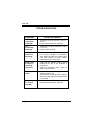
TROUBLESHOOTING
SYMPTOM
CAUSE and REMEDY
Lo is
continually
displayed
−
Temperature is below minimum (13.5°F or 10.0°C).
−
Probe is disconnected or defective.
Hi is
continually
displayed
−
Temperature is above maximum (105.0°
F or 41° C).
Probe is short circuited.
Fan(s) or
heater not
operating
−
Verify whether the fan LED is on. If LED
is on yet fan or heater is not operating,
verify wiring, fan and fuse. Refer Figure
6 for fuse location. If fuse is blown,
replace with fuse of same type.
Stage 3 Fan
or Heater is
operating
erratically
−
Verify that the software setting switch
located at the rear of the faceplate is
properly set.
Verify the minimum rating (10mA at
230V or 20mA at 230V.
Display is
blank
−
F2 displayed
for relative
humidity
Page 48
−
−
−
Verify that the line voltage selector
switch is properly set.
Verify that the 10 pin flat cable between
the main board and the faceplate board
is connected.
−
−
Humidity is below minimum (30%).
Probe is disconnected or defective.
APPENDIX
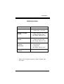
SPECIFICATION
DESCRIPTION
*
VALUE
INPUT POWER
−
−
12 AMP
115/230 -20%, +10% VAC
STAGE 1 (variable
speed)
−
−
−
6 AMP; inductive 115V / 230V
10 AMP; max (fuse 10A)
Min. Rating 150mA at 115V*
STAGE 2 (variable
speed)
−
−
−
6 AMP; inductive 115V / 230V
10 AMP; max (fuse 10A)
Min. Rating 150mA at 115V*
STAGE 3 (dry relay
contact)
Not Fused
−
−
−
−
10 AMP ; 115V/230V
1/2 HP @ 115V
1 HP @ 230V
Min. Rating 10mA at 115V*
ALARM (dry relay
contact)
−
2 AMP; 30V DC
Relay will not function properly if load is smaller than
min. value.
Page 49
ECS-3M
RECORD FORM
Dial
Option
Default setting
1
Main Set Point Temperature
77° F
25° C
2
Fan 1 Differential
4° F
2° C
3
Fan 1 Min Speed
24%
24%
4
Fan 1 Duty Cycle Timer
ON
ON
5
Fan 2 Relative Set Point
4° F
2° C
6
Fan 2 Differential
4° F
2° C
7
Fan 2 Min Speed
24%
24%
8
Heater/Fan 3 Relative Temp.
-3° F
-1° C
9
Reduction per day
OFF
OFF
2nd Function
1
Relative Humidity
65%
65%
2
Fan 1 Motor Compatibility
2
2
3
Fan 1 Min Speed For Humidity
50%
50%
4
Fan 1 Duty Cycle Period
3 min
3min
6
Fan 2 Motor Compatibility
2
2
8
Heat/Fan 3 Differential
2° F
1° C
9
Minimum Ramping Limit
65° F
18° C
10
Lo Temperature Limit
-9° F
-5° C
11
High Temperature Alarm
20° F
12° C
Page 50
User setting
WARRANTY
Limited Warranty
The manufactured equipment and supplied
components have gone through rigorous
inspection to assure optimal quality of product and
reliability. Individual controls are factory tested
under load, however the possibility of equipment
failure and/or malfunction may still exist.
For service, contact your local retailer or supplier.
The warranty period shall be for two years from
manufacturing date. Proof of purchase is required
for warranty validation.
In all cases, the warranty shall apply only to
defects in workmanship and specifically exclude
any damage caused by over-voltage, short circuit,
misuse, acts of vandalism, fortuitous events, acts
of God, flood, fire, hail, lightning or any other
natural disaster. Any unauthorized work,
modification or repair on this product automatically
voids the warranty and disclaims the manufacturer
from all responsibility.
The manufacturer assumes only those obligations
set forth herein, excluding all other warranties or
obligations. This warranty stipulates that in all
cases the manufacturer shall be liable only for the
supply of replacement parts or goods and shall not
be liable for any personal injury, damages, loss of
profits, interrupted operations, fine contravention of
the law or damages to the production of the
PURCHASER and the PURCHASER shall take up
the defense and hold the manufacturer faultless
regarding any legal or extra legal proceedings,
notice, or claim by the customer or by a third party,
and regarding any legal and extra legal expenses
and fees brought forward on by such damages.
Page 51
ECS-3M
MAV ECS-3M Ver: 2.1
April 1995
Rev. June 2001
Page 52