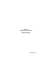
1
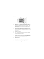
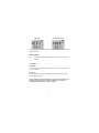
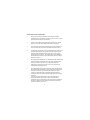
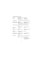
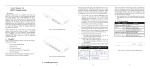
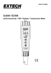
MODEL 470 PORTABLE
CONDUCTIVITY/TDS METER
OPERATING MANUAL
MANUEL D’UTILISATION
BETRIEBSHANDBUCH
MANUALE OPERATIVO
MANUAL DE OPERAÇÂO
MANUAL DE FUNCIONAMIENTO
470 250/REV A/09-00
MODEL 470 PORTABLE
CONDUCTIVITY/TDS METER
OPERATING MANUAL
CONTENTS
Introduction
Specification
Installation
Displays
Controls
Probe Zero
Preparation of Conductivity Standards
Operation
Calibration:
With Known Cell Constant
On Standard Solution (AVE)
On Non-Standard Solution (MVE)
Sample Measurement
Error Codes
Good Practice Guidelines
Troubleshooting Guide
Battery Replacement
Optional Accessories
EC Declaration of Conformity
1
1-2
2
3
4
5
5
5
6
6
6
7
7-8
8
9
10-11
11
11
12
MODEL 470 PORTABLE
CONDUCTIVITY/TDS METER
OPERATING MANUAL
INTRODUCTION
The Model 470 is a general purpose, hand held Conductivity/TDS meter
offering direct calibration on standard solutions or by direct cell constant
entry. The custom backlit liquid crystal display simultaneously shows
temperature compensated conductivity or TDS and temperature. The
conductivity/TDS range is automatically selected for optimum resolution
and temperature compensated using an adjustable temperature coefficient.
The instrument is housed in a robust, ergonomically designed case that is
environmentally protected to IP67. Calibration errors are clearly
indicated together with the parameter in error.
An indication of battery life is also permanently shown on the display. An
automatic switch off facility helps to conserve battery life.
SPECIFICATION
Conductivity
Ranges:
Resolution:
Accuracy:
TDS Ranges:
Resolution:
Accuracy:
0 to 1999mS* (*only with cell constant >5)
0 to 199.9mS
0 to 19.99mS
0 to 1999µS
0 to 199.9µS
0 to 19.99µS
1mS*/0.1mS/0.01mS/1µS/0.1µS/0.01µS
±0.5% ±2 digits
0 to 1999g/l* (* only with cell constant >5)
0 to 199.9g/l
0 to 19.99g/l
0 to 1999mg/l
0 to 199.9mg/l
0 to 19.99mg/l
1g/l*/0.1g/l/0.01g/l/1mg/l/0.1mg/l/0.01mg/l
±0.5% ±2 digits
1
Temperature Range:
Resolution:
Accuracy:
ATC & Manual Ranges:
Cell Constant:
Reference Temperature:
Temperature Coefficient:
E/C Ratio:
Auto StandardRecognition:
Battery Life Indication:
Probe Input:
Power:
Size:
Weight:
-10 to +105°C / 14 to 220°F
0.1°C / 1°F
±0.5°C / ±1°F
0 to +100°C / 32 to 212°F
Digitally settable 0.01 to 19.99
25°C
0.00 to 4.00%/°C linear
0.6
10µS, 84µS, 1413µS or 12.88mS
(with manual override)
<25%, 25-50%, 50-75%, 75-100%
Mini-DIN conductivity/temperature
2 AA cells
175(l) x 75(w) x 35(d)mm
250g
INSTALLATION
Unpack the instrument and ensure the following items are present:
1. Model 470 Conductivity Meter (470 201)
2. Conductivity/Temperature Probe (epoxy bodied) (027 298)
3. 2 x AA alkaline batteries (021 007)
Optional accessories which may have been ordered:
1. Carrying Case (033 269)
2. Protective boot (985 531)
3. Conductivity Standard 10µS (025 139)
4. Conductivity Standard 84µS (025 164)
5. Conductivity Standard 1413µS (025 138)
6. Conductivity Standard 12.88mS (025 156)
7. Cell K=1, epoxy bodied (027 298)
8. Cell K=0.1, epoxy bodied (027 801)
9. Cell K=10, epoxy bodied (027 802)
2
DISPLAYS
1.
Main display - 3½ digit backlit LCD providing direct readout of
conductivity (in µS or mS) and total dissolved solids (TDS)
(in mg/l or g/l). The display will also show Underrange (-1) and
Overrange (1) symbols if the instrument is reading outside the
operating ranges.
2.
Secondary display - 4 digit display showing temperature (manual
temperature compensation value or probe temperature) in °C or °F,
the cell constant value (K) or the temperature coefficient value as a
percentage (%).
3.
Reading hold indication.
4.
CAL - will be displayed momentarily to indicate auto standard
recognition calibration or probe zero.
5.
Battery life indication - 4 levels will be shown ranging from <25%,
25-50%, 50-75% and 75-100%. Sensor calibration data and user
parameters are retained during battery replacement.
6.
Mode annunciators.
7.
Manual temperature compensation/calibration indication.
8.
OR annunciator - indicates an out of range condition.
3
CONTROLS
Hold
The main operating mode displays conductivity readings and
temperature, which can be held by pressing the Hold key
(subsequent Hold key press returns to live measurement).
I:O
Switches the instrument on and off. The instrument will
automatically switch off after 30 minutes if no keys are pressed.
Back light. Pressing this key will illuminate the back light for 10
seconds. It should be noted that, if used excessively, this will
degrade battery life.
56
Enables adjustment of conductivity, cell constant and temperature
coefficient values.
Cal
Pressing the Cal key illuminates the Cal mode indicator. A
subsequent Cal key press calibrates to the nearest conductivity
standard or probe offset to zero (if the reading is less than 2µS).
Alternatively, the 56 keys can be used to set the
conductivity display to the required value, which must be
confirmed by pressing the Cal key. The Cal key is used to perform
a conductivity calibration on 10µS, 1413µS, 12.88mS or 0µS. In
TDS mode the unit calibrates to 6.6mg/l, 933mg/l, 8.5g/l or
0mgl. Calibration errors are indicated for 3 seconds by an error
code displayed on the secondary display, together with the
parameter in error displayed on the primary display.
Mode
°C or °F temperature units can be selected by pressing the mode
key for 3 seconds. Pressing the Mode key changes to TDS
measurement and temperature display. Subsequent mode key
presses will go through TDS and cell constant display (adjustable
via 56 keys) and TDS and temperature coefficient display
(adjustable via 56 keys).
4
PROBE ZERO
Pressing the Cal key illuminates the Cal mode indicator. A subsequent Cal
key press calibrates to the nearest conductivity standard or probe offset to
zero (if the reading is less than 2µS).
PREPARATION OF CONDUCTIVITY STANDARDS
Suitable conductivity standards are available commercially or these can be
made up as required from A.R. reagents with reference to the relevant
physical tables.
Method for general purpose conductivity standard
1) Accurately weigh out 0.746 grammes of dried A.R. grade Potassium
Chloride (KCl).
2) Dissolve in 1 litre of good quality deionised water.
This produces a 0.01N solution with a conductivity of 1413µS @ 25°C.
Storage
This solution must be stored in a plastic container and the air space should
be kept to an absolute minimum. The shelf life of 1 week can be increased
by storing below 4°C, but where any doubt exists about the viability of
stored solution a fresh batch should be prepared.
OPERATION
Switch the instrument on by holding down the I/O key for 1-2 seconds. All
display segments will be illuminated for approximately 2 seconds.
Remove the conductivity cell from the packaging and ensure it is in good
condition (not broken). Connect the cell to the instrument.
5
CALIBRATION
Auto standard recognition operates over the range of 0 to 100°C and will
recognise 10µS, 84µS, 1413µS or 12.88mS. Alternative values may be
entered during the calibration sequence by using the 56 keys to set
the preferred values.
NOTE: Manual temperature compensation should be entered prior to
commencing a calibration sequence. (If the displayed reading is altered
the auto standard recognition feature will be disabled. To retrieve the
auto standard recognition values it is necessary to exit the calibration
sequence by pressing the Mode key).
a) WITH KNOWN CELL CONSTANT
Connect a standard pre-calibrated cell
to the unit. Select K using the Mode
key. The display will show the current
cell constant.
The 56 keys can then be used to adjust the cell constant to the value
indicated on the conductivity cell body.
b) ON STANDARD SOLUTION (Auto Value Regognition)
Place the conductivity cell into the calibration standard. Press the Cal key
and allow the reading to stabilise prior to pressing the Cal key again to
complete the calibration.
To abort the calibration sequence press the Mode key.
6
c) ON NON- STANDARD SOLUTION (Manual Value Entry)
Place the conductivity cell into the calibration standard. Enter the preferred
calibration standard value using the 56 keys. (If the displayed reading
is altered the auto standard recognition feature will be disabled. To retrieve
the auto standard recognition values it is necessary to exit the calibration
sequence by pressing the Mode key).
Press the Cal key and allow the reading to stabilise. Press the Cal key again
to complete the calibration. To abort the calibration sequence press the
Mode key.
SAMPLE MEASUREMENT
Conductivity is a temperature dependent measurement. All substances have
a conductivity coefficient which varies from 1%/°C to 3%/°C for most
commonly occurring substances. The temperature coefficient defaults to
2%/°C, this being adequate for most routine determinations. Conductivity
readings varying with temperature may be due to the substances under test
having a coefficient other than the typical value of 2%/°C. To eliminate this
variation it is necessary to maintain all samples at the reference temperature
by use of a thermostatic water bath or equivalent.
Adjustment may be made by selecting %
on the secondary display via the Mode key
and then using the 56keys to the
required value.
After calibration the measurement of samples is carried out by immersing
the cell in the samples, allowing the reading to stabilise and recording the
result. The cell should be rinsed in deionised water between each sample to
avoid contamination, shaken to remove internal droplets, and the outside
wiped prior to immersion in the next sample.
7
TDS mode
Conductivity mode
On completion of sample measurement the cell should be thoroughly rinsed
in deionised water.
ERROR CODES
Err 1
indicates that the calculated cell constant (K) is out of range (0.01
to 19.99).
STORAGE
Short Term
The cell should be immersed in deionised water to keep the plates in a
wetted condition.
Long Term
The cell should be thoroughly rinsed in deionised water, the exterior body
wiped and then stored dry.
NOTE: When preparing the cell for storage the plate area must not be
wiped dry. When using a dry cell initial stability on re-use may be
impaired until the cell plates become re-wetted.
8
GOOD PRACTICE GUIDELINES
1.
The presence of particulate matter in the sample can lead to
unstable and non-reproducible results. If necessary filter, or allow
the particles to settle prior to immersion.
2.
Ensure no air bubbles are trapped in the measuring cell. Gentle
agitation of the cell should ensure that bubbles are purged.
3.
The entire plate area must be immersed in the solution under test.
The slots in the side of the sensor should be below the surface.
4.
It is advisable to clean the sensor if contamination is evident. This
should be approached in a progressive manner, beginning with
deionised water and progressing to other solvents or a soft air
brush if the deposits persist. The carbon plates can be damaged
and should not come into contact with anything which is likely to
abrade their surface.
5.
The temperature coefficient is very dependent on the solution being
measured and its concentration level. The effect of temperature
change on conductivity can be very significant, and if the
temperature coefficient is not known it is wise to measure all
samples at the same temperature.
6.
The TDS mode displays results which have been calculated from
the measurement of conductivity. The salinity mode assumes that
the major constituent responsible for the conductivity of the
solution is sodium chloride. If significant quantities of other
conductive species are present then the displayed results could be
inaccurate.
Likewise, the TDS mode assumes some knowledge of the
electrolyte balance of the analyte. The EC ratio parameter
found in the set up routine allows selection of a factor suitable for
the solution under test. Most analysers which do not offer this
option use a default value of 0.6.
9
TROUBLESHOOTING GUIDE
FAULT
PROBABLE CAUSE
ACTION
No power
Battery failure
Battery polarity incorrect
Replace batteries
Refit batteries
Unstable display
Conductivity cell defective Replace conductivity cell
Check cell connection to
Display permanently Intermittent or no
instrument
under or over range connection
Conductivity cell defective Replace conductivity cell
Contaminated solutions Replace solutions
Intermittent display Conductivity cell not fitted Check connections
correctly
I/O key not held down
long enough
Retry holding key for 2
seconds
keys not
working
Operating in incorrect
mode
Refer to operation section
of manual
Back light not on/
goes out
10 second time elapsed/
normal function
Recheck
I/O switch not
working
56
Hold function selected
Unable to adjust
manual temperature Incorrect mode of
operation
Reading drifts
Deselect Hold function
Reselect mode
Conductivity cell stored Allow to soak for 2 hours
dry
CO2 absorbtion by sample Noticeable for low
conductivity - do not
allow sample to stand in
unstoppered bottles
10
FAULT
Non linear readings
Poor reproducibility
ACTION
PROBABLE CAUSE
Conductivity cell not zeroed Zero conductivity cell
Carryover between solutions Rinse cell in distilled
water between
measurements
BATTERY REPLACEMENT
To fit new batteries; loosen the battery compartment cover (the screws are
captive in the cover), remove and carefully discard the used batteries. Fit the
new batteries, type R6, AA or AM3, ensuring the correct polarities are
observed, as indicated on the moulding. Refit the battery compartment
cover, ensuring that the fixings are secured into place, but are not
overtightened.
OPTIONAL ACCESSORIES
The following list of items are available for use with the Model 470:
033 269
985 531
025 139
025 164
025 138
025 156
027 298
027 801
027 802
Carrying Case
Protective Boot
Conductivity Standard 10µS
Conductivity Standard 84µS
Conductivity Standard 1413µS
Conductivity Standard 12.88mS
Cell K=1, epoxy bodied
Cell K=0.1, epoxy bodied
Cell K=10, epoxy bodied
11
EC Declaration of Conformity
JENWAY Model 470 Conductivity/TDS Meter complies with the following
European Standards:
EN 50081-1:1992 Electromagnetic compatibility - Generic emission
standard
EN 61326:1998 Electrical equipment for measurement, control and
laboratory use - EMC requirements
EN 61010-1:1993 Safety requirements for electrical equipment for
measurement, control and laboratory use
Following the provision of:
EMC Directive - 89/336/EEC and Low Voltage Directive - 73/23/EEC
Martyn J. Fall
Managing Director, Jenway Limited,
Gransmore Green, Felsted, Dunmow,
Essex, CM6 3LB, England
12