1
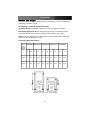
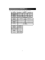
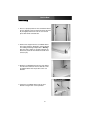
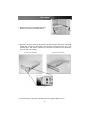
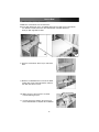
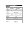
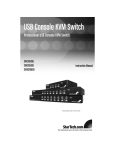
Cabinet Console
1U Cabinet Console with 15" TFT Monitor
1U Cabinet Console with 17" TFT Monitor
1U Cabinet Console with 19" TFT Monitor
1UCABCONS
1UCABCONS17
1UCABCONS19
Instruction Manual
Actual product may vary from photo
FCC Compliance Statement
This equipment has been tested and found to comply with the limits for a Class B digital
device, pursuant to part 15 of the FCC Rules. These limits are designed to provide
reasonable protection against harmful interference in a residential installation. This
equipment generates, uses and can radiate radio frequency energy and, if not installed
and used in accordance with the instructions, may cause harmful interference to radio
communications. However, there is no guarantee that interference will not occur in a
particular installation. If this equipment does cause harmful interference to radio or
television reception, which can be determined by turning the equipment off and on, the
user is encouraged to try to correct the interference by one or more of the following
measures:
• Reorient or relocate the receiving antenna.
• Increase the separation between the equipment and receiver.
• Connect the equipment into an outlet on a circuit different from that to which the
receiver is connected.
• Consult the dealer or an experienced radio/TV technician for help.
Use of Trademarks, Registered Trademarks, and
other Protected Names and Symbols
This manual may make reference to trademarks, registered trademarks, and other
protected names and/or symbols of third-party companies not related in any way to
StarTech.com. Where they occur these references are for illustrative purposes only and
do not represent an endorsement of a product or service by StarTech.com, or an
endorsement of the product(s) to which this manual applies by the third-party company in
question. Regardless of any direct acknowledgement elsewhere in the body of this
document, StarTech.com hereby acknowledges that all trademarks, registered
trademarks, service marks, and other protected names and/or symbols contained in this
manual and related documents are the property of their respective holders.
Instruction Manual
Table of Contents
Introduction . . . . . . . . . . . . . . . . . . . . . . . . . . . . . . . . . . . . . . . . . . . . . . . . . . . . .1
Features . . . . . . . . . . . . . . . . . . . . . . . . . . . . . . . . . . . . . . . . . . . . . . . . . . . . . . . .1
Before You Begin . . . . . . . . . . . . . . . . . . . . . . . . . . . . . . . . . . . . . . . . . . . . . . . . .2
System Requirements . . . . . . . . . . . . . . . . . . . . . . . . . . . . . . . . . . . . . . . . . . .2
Assembly . . . . . . . . . . . . . . . . . . . . . . . . . . . . . . . . . . . . . . . . . . . . . . . . . . . . . . .4
Installation . . . . . . . . . . . . . . . . . . . . . . . . . . . . . . . . . . . . . . . . . . . . . . . . . . . . . .7
Front Panel functions . . . . . . . . . . . . . . . . . . . . . . . . . . . . . . . . . . . . . . . . . . . . .8
KVM Control and Status . . . . . . . . . . . . . . . . . . . . . . . . . . . . . . . . . . . . . . . . .8
LCD Panel Control . . . . . . . . . . . . . . . . . . . . . . . . . . . . . . . . . . . . . . . . . . . . . .8
LCD Panel Power Switch . . . . . . . . . . . . . . . . . . . . . . . . . . . . . . . . . . . . . . . .8
Replaceable Keyboard . . . . . . . . . . . . . . . . . . . . . . . . . . . . . . . . . . . . . . . . . . . .9
Replaceable Touch Pad . . . . . . . . . . . . . . . . . . . . . . . . . . . . . . . . . . . . . . . . . . .9
Specifications . . . . . . . . . . . . . . . . . . . . . . . . . . . . . . . . . . . . . . . . . . . . . . . . . .11
Technical Support . . . . . . . . . . . . . . . . . . . . . . . . . . . . . . . . . . . . . . . . . . . . . . .12
Warranty Information . . . . . . . . . . . . . . . . . . . . . . . . . . . . . . . . . . . . . . . . . . . .12
i
Instruction Manual
Introduction
Thank you for purchasing a StarTech.com 1U Cabinet Console. This console offers the
ultimate in computer management, especially for applications where space is at a
premium. The console uses a flat panel Active Matrix TFT display (please see Features
for a detailed outline of the resolutions available). The drawer can be pulled out for
operation from the rack on sliding rails that latch in the extended position and when not in
use, the display can be folded down, locked, and secured while pushed in. With different
rear bracket & extension kits, the console can be mounted on rack cabinets of various
depths. The console comes with standard PS/2 keyboard and mouse connectors as well
as an HDB15 VGA connector for computer or KVM switch connection.
Features•
• 1UCABCONS: Flip-open 15” TFT LCD panel supports 1024 x 768 @60/70/75
• 1UCABCONS17: Flip-open 17” TFT LCD panel supports 1280 x 1024 @60/70/75
• 1UCABCONS19: Flip-open 19” TFT LCD panel supports 1280 x 1024 @60/70/75
• Standard 19" 1U rack drawer
• Modular design
• Full 105 key, low-profile, sturdy keyboard built-in
• Standard connectors for PC connection
• Locking mechanism locks the drawer when pulled out, pushed in or folded down
• Supports replaceable keyboard, mouse and module selection
• Ergonomic hand rest design
• For rack cabinet with depth from 20" (50cm) and up (with appropriate Rear bracket &
extension kit)
• Quick and easy installation
• Optional KVM switch available
1
Instruction Manual
Before You Begin
To ensure a quick and easy installation, please read through this section carefully before
attempting to install the console.
The following are required to install the console:
1U Cabinet Console: assembled "LCD panel + keyboard + mouse pad" drawer
Rear bracket & extension kit: This kit contains two pieces of rear brackets and two
extensions. Make sure you have the correct kit to fit the depth of your cabinet.
Note: the following length is measured between "front pole and rear pole inside a rack
cabinet" not the outside depth of a rack:
Front Pole to Rear Pole Distance
Front 1UCABCONS CABCONS30KIT 1UCABCONS17 CABCONS42KIT
pole to
rear pole
distance
( Depth )
cm
inch
cm
inch
cm
inch
cm
inch
1UCABCONS19
cm
inch
Minimum 49.5 19 1/2
57.5
22 5/8
67.5
26 5/8
77.5
30 1/2
87.5
34 1/2
Maximum
70.5
27 3/4
80.5
31 5/8
90.5
35 5/8
100.5
39 3/4
22 3/8
Depth
Depth
57
Top view of rack cabinet with console installed
2
Instruction Manual
The KVM Module can be connected to a console, or be used as a stand-alone KVM
Switch. There are three major categories: PS/2, USB and Sun Interfaces:
Type
Model name
No. of Console Ports
No. of Computer Ports
OSD Menu
OSD Menu
Cable Type
PS/2 KVM
CAB832DS
CAB1631D
Type
Model name
CAB1631D1U
2
1
8
16
Yes
Yes
1U
2U
SVPS23N1_xx PS23N1THINxx
1
16
Yes
1U
SVECONxx
Hybrid KVM
CAB831HD
Interface
CAB1631HD
PS/2, USB
No. of Console Ports
1
1
No. of Computer Ports
OSD Menu
Height
8
16
Yes
1U
2U
PS2 – SVECONx
USB - SVECONUSx
Cable Type
Type
IP KVM
Model name
CAB1641HDI
Interface
PS/2, USB
No. of Console Ports
1
No. of Computer Ports
16
OSD Menu
Yes
Height
1U
Cable Type
PS2 – SVECONx
USB - SVECONUSx
3
Instruction Manual
Assembly
1. Choose a proper position for the rack drawer. Mount
the rear brackets (from the Rear bracket & extension
kit) and lightly fasten them onto the rear vertical
poles. Both will be removed later.
2. Remove the stopper from the assembled drawer.
The safety stopper is designed to stop the drawer
from sliding out during transportation. Warning:
After the safety stopper is carefully removed, the
drawer may slide out when tilted and could cause
serious injury.
3. Slide the assembled drawer into the rack cabinet
from the front and insert the two slide rails of the
assembled drawer into the pockets of the rear
brackets.
4. Fasten the assembled drawer onto the front
brackets using the four screws provided.
4
Instruction Manual
5. Remove both of the rear brackets. The front
brackets now hold the assembled drawer.
6. Attach the extensions (from the Rear bracket & extension kit) to both sides of the KVM
module box. Please note the length of the extensions and mount them in one of the
following ways. Also, please note that for a 2U model, the extensions are mounted to
the lower half of the module.
Short extension attachment
Long extension attachment
Wider side of the extension on
top
7. The rear brackets, extensions and slide rails have a tight fit. Make sure you
5
Instruction Manual
follow these steps for easy installation.
A.Slide the rear brackets onto the extensions.
B. Insert both sliding rails of the assembled drawer into the tight space formed by the
rear brackets and the extensions. The KVM module should be pushed in
evenly on both right and left sides.
A
B
8. Push the rear brackets all the way in and fasten
them.
9. Slide the assembled drawer out. Push the KVM
module box evenly toward the drawer, and then
lock both units by the screws.
10. Make sure the C-36 connectors are firmly
connected during step 10.
11. Connect the power supply to the power jack
on the KVM module to complete the installation.
6
Instruction Manual
Installation
Consider the console as a set of keyboard, mouse and monitor, and connect it directly to
a computer with the 1 to 1 KVM module:
Male-to-male mini-DIN6 for Keyboard
Male-to-male mini-DIN6 for mouse
Male-to-female HDB15 for VGA
Or, the console with the 1 to 1 KVM module can be connected to a KVM switch as
shown below:
Male-to-female
HDB15 for VGA
Male-to-male mini-DIN6 for Mouse
Male-to-male mini-DIN6 for Keyboard
7
Instruction Manual
Front Panel Functions
1
2
3
4
10
5
6
7
8
9
KVM Control and Status:
(This section is effective only when a KVM switch module is connected.)
1. Computer Selection Pad - Press one of these pushbuttons to select a computer. For
16 port models, 1-8 represent the lower 8 ports, while A-H indicates the higher 8 ports.
Port 1 and A share the same pushbutton; if port 1 is already selected, tap its
pushbutton to select port A. If port 1 is not selected, press and hold pushbutton 1 for
two seconds to select port A.
2. Selected Computer Indicator - One of the indicators turns red when a corresponding
computer is selected by pushbuttons, hotkey or OSD menu.
3. Local Console in Operation - When a computer is accessed through the console,
this will illuminate green.
4. Remote Console in Operation - This will illuminate green when a computer is
accessed by another set of keyboard/mouse/monitor connected to the Remote
console when the KVM Switch Function Module is a 2-console KVM.
LCD Panel Control:
5. LCD Panel Menu - These buttons invoke the OSD menu for the LCD panel and acts
as menu selection.
6. LCD Panel Adjustment - Lets you adjust settings for the LCD panel.
Keyboard Status and LCD Panel Power Switch:
7. Num Lock - Keyboard Num Lock status
8. Caps Lock - Keyboard Caps Lock status
9. Scroll Lock - Keyboard Scroll Lock status
10. LCD Panel Power Switch
8
Instruction Manual
Replaceable Keyboard
The keyboard is replaceable, in the event of language changes or maintenance. To
replace the keyboard, tilt it up, locate the mini-USB cable underneath the keyboard and
gently unplug it. While installing the replacement keyboard, please ensure that you
extend just enough of the cable to keep the keyboard flat inside the tray.
Triangular Mark
Please note: There is a round hole under the drawer, which can be used to pass one finger
through allowing for easier removal of the keyboard (pushing upwards).
Please note: The triangular mark on the mini USB connector must face outwards.
Replaceable Touch Pad
The built-on Touchpad offers “wheel mouse” functionality. The area of the Touch Pad to
the right side of the two small triangular marks is the simulated "wheel" as shown below:
1
1
1 - Triangular Marker
Scroll
Wheel
Area
2 - Left Mouse Button
3 - Right Mouse Button
2
9
3
Instruction Manual
To remove the Touch Pad, press the tab underneath it upward to release the latch, and then
slide it outwards until the Touch Pad can be lifted up clear from the notches, as shown in
the figure on the right. The Touch Pad is attached by a piece of mini-USB cable. To install
the Touch Pad, extend just enough mini-USB cable and slide the Touch Pad all the way in
till you hear a click sound as it is locked in position.
Please Note: The triangular mark on the mini-USB connector must face outwards.
10
Instruction Manual
Specifications
Specifications
15” LCD Panel
17” LCD Panel
Active Display Area
Pixel Pitch (mm)
Resolution
Color Pixel Arrangement
304.1 x 228.1 (mm)
0.297(H) x 0.297(V)
1024 x 768 @60/70/75Hz
19” LCD Panel
337.920 x 270.336 (mm)
376.32x301.056 (mm)
0.264 (H) x 0.264 (V)
0.294(H) x 0.294(V)
1280 x 1024 @60/70/75Hz
RGB vertical strip
Display Mode
Normally White
Brightness(cd/m2)
Contrast Ratio
250 (center)
350:1
Display Color
16.2M colors (RGB 6-bits data)
User Control
Input Signal
260 (center)
450:1
250 (center)
500:1
16.7M colors (RGB 8-bits data
OSD Control (auto saving)
RGB analog, H/V separate
Plug-n-Play VESA
VESA DDC 1/2B
Power Consumption
33W
37W
40W
Viewing Angle
-70~70(H)
-60~60(V) (Typ.)
-80~80(H)
-80~80(V) (Typ.)
-85~85(H)
-85~85(V) (Typ.)
Backlight Unit
2 CCFLs edge-light
(top/bottom)
4 CCFLs edge-light
(top/bottom)
Operating Temperature
StorageTemperature
0 to +50 (°C)
-20 to +60 (°C)
Operating Humidity
Relative Humidity 8% ~ 95%
Non-Operating Humidity
Power Supply Input
Voltage
Regulatory Certifications
Full range, 100V AC to 240V AC
CE, FCC for the product. UL, TUV, CE for power supply
Mouse Touch Pad
PS/2
Power Management
VESA DPMS compliant
ON mode = 23.2W
STANDBY mode <= 1W
SUSPEND mode <= 1W
OFF mode <= 1W
95% RH
11
Instruction Manual
Technical Support
StarTech.com’s lifetime technical support is an integral part of our commitment to provide
industry-leading solutions. If you ever need help with your product, visit
www.startech.com/support and access our comprehensive selection of online tools,
documentation, and downloads.
Warranty Information
This product is backed by a one-year warranty. In addition, StarTech.com warrants its
products against defects in materials and workmanship for the periods noted, following
the initial date of purchase. During this period, the products may be returned for repair, or
replacement with equivalent products at our discretion. The warranty covers parts and
labor costs only. StarTech.com does not warrant its products from defects or damages
arising from misuse, abuse, alteration, or normal wear and tear.
Limitation of Liability
In no event shall the liability of StarTech.com Ltd. and StarTech.com USA LLP (or their
officers, directors, employees or agents) for any damages (whether direct or indirect,
special, punitive, incidental, consequential, or otherwise), loss of profits, loss of business,
or any pecuniary loss, arising out of or related to the use of the product exceed the
actual price paid for the product.
Some states do not allow the exclusion or limitation of incidental or consequential
damages. If such laws apply, the limitations or exclusions contained in this statement
may not apply to you.
12
About StarTech.com
StarTech.com is “The Professionals’ Source for Hard-to-Find Computer
Parts”. Since 1985, we have been providing IT professionals with the
quality products they need to complete their solutions. We offer an
unmatched selection of computer parts, cables, server management
solutions and A/V products and serve a worldwide market through our
locations in the United States, Canada, the United Kingdom and Taiwan.
Visit www.startech.com for complete information about all our products
and to access exclusive interactive tools such as the Parts Finder and the
KVM Reference Guide. StarTech.com makes it easy to complete almost
any IT solution. Find out for yourself why our products lead the industry in
performance, support, and value.
Revised: 16 November 2007 (Rev. A)