1
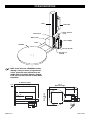
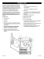
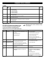
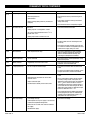
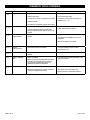
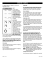
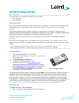
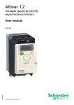
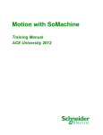
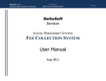
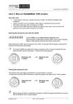
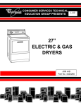
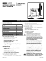
H-2957
AUTOMATIC STRETCH
WRAP DISPENSER
SYSTem specifications
MACHINE DIMENSIONS
•Adjustable raise and lower speeds
•Automatic height detection photoelectric sensor
Length
116"
Width
65"
Height
92"
•¼ HP 3-phase AC motor, ½ HP AC frequency drive
Turntable Diameter
65"
•Adjustable film force
Turntable Height from Floor
3 1/4"
•200% / 250% average pre-stretch level
Wrapping Height
80"
•10" diameter roll capacity
Operation Space
125 x 70 x 100"
•20" height roll capacity
Maximum Load Size
56 x 56 x 80"
Approximate Shipping Weight
1220 lbs
ELECTRICAL SPECIFICATIONS
•120 VAC, 60 Hz, Single-phase, 15 AMP
•NEMA-12 rated electrical panel
•Operating temperature: +32˚F to +110˚F
•Lockable disconnect switch
•NEC wiring standard
•Programmable Logic Controller (PLC) with input/
output diagnostic lights
TURNTABLE SYSTEM
•Low Profile: ½ HP 3-phase AC motor, ½ HP AC
frequency drive
•20-30 loads per hour (spiral)
•12 RPM turntable maximum speed
•4,000 lbs turntable maximum load capacity
FILM CARRIAGE / ELEVATOR SYSTEM
•½ HP 3-phase AC motor, ½ HP AC frequency drive
PAGE 1 OF 17
FILM DELIVERY SYSTEM
CAUTION! Motor control equipment and
electronic controllers are connected to
hazardous line voltages. When servicing
drive and controllers, there may be exposed
components with housings or protrusions at or
above line potential. Extreme care should be
taken to protect against shock.
The user is responsible for conforming to all
applicable code requirements with respect
to grounding all requirements. Do NOT use
extension cords to operate the equipment.
Disconnect AC input power before checking
components, performing maintenance,
cleaning up, and when the machine is not in
use. Do NOT connect or disconnect wires and
connectors while power is applied to circuit.
Wiring work should be carried out only by
qualified personnel. There is a danger of
electric shock or fire.
WARNING! Loose clothing must NOT be worn
while the machine is in operation. Stay clear of
moving parts while the machine is running.
0411 IH-2957
SYSTem description
Tower
Control Box
Stretch Selector
Cover
Photo Sensor
Motor Cover
Film Carriage
Frame
Turntable
Foot Security Pan
Auto Film Cut
Solenoid
NOTE: Shown below are STANDARD assembly
drawings. It may not reflect your purchased
system, especially when optional items are
added. Refer to assembly drawings shipped
inside the electrical enclosure for more detail
information.
3.25"
92" Machine Height
80" Wrapping Height
101.5"
Machine Length
35.5"
65"
Turntable Size
41"
12.5"
8"
"
10
PAGE 2 OF 17
0411 IH-2957
SYSTEM SET-UP
MACHINE PLACEMENT
Power and Safety Wiring Checks
Place the Automatic Stretch Wrap Machine close to
an area where you will be wrapping your pallet loads.
Make sure that there is sufficient room to load/unload
the machine and that you do not stretch the wiring
cable. Remember, you will need to provide electrical
service to a 120 VAC, 15-AMP outlet.
1. Using a voltage meter, check the AC voltage
coming to the system to insure proper voltage is
present.
Floor weight bearing tolerance
The floor must be able to bear the weight of the
machine, the weight of the maximum load, plus a safety
factor. The floor must also be able to tolerate the stress
of the machine’s operation. If the fork trucks will operate
on the same weight bearing area, add the weight
of the trucks to the weight bearing stress tolerance
requirements.
WARNING! The Stretch Wrap Machine must be
anchored securely to the floor, using the type
of anchor recommended for your floor.
MACHINE SET-UP
1. Place skidded machine close to the designated
wrap area. Remove all shipping fasteners holding
the machine to the pallet. The machine may be
crated with the tower tilted down with the motor
cover front carriage roller removed for shipping
purpose.
2. Place forks of the forklift through the tubes provided
at the rear base of the module, remove the machine
from these skids, and place it at the designated
wrap area.
3. If the optional ramp (H-2958) is purchased:
Select a ramp position as illustrated below. The
ramp can be positioned anywhere in a 180° rotation
around the front of the turntable. There should be a
¼" gap between the turntable and the ramp. The
ramp should be fully supported by the floor. Both the
ramp and the machine should be lagged to the floor.
2. Make sure the "E-STOP" button is pressed in. Turn the
disconnect switch to ON position.
3. Pull the "E-STOP" button on the operator panel out.
Power should be applied to the frequency drives,
operating touch-panel, photoelectric sensors,
switches, and LED’s.
4. Press the "E-STOP" button. Make sure all machine
power is completely removed when the "E-STOP" is
depressed. Pull the "E-STOP" button out to resume.
5. Open the film carriage door. Make sure all machine
power is completely removed when the carriage
door is open. Close the film carriage door to resume.
6. Open the electrical control box. Make sure all
machine power is completely removed when the
electrical control box is open. Close the electrical
control box to resume.
7. Trip the carriage foot security bar. Make sure all
machine power is completely removed when the
carriage foot security bar is tripped. Clear the bar to
resume.
PLC's Input Module Checks
1. Open the electrical control box, and insert the key
latch onto the safety door switch.
2. Depress push buttons and activate selector
switches on the operator panel, check for each
corresponding input lights on the front face of PLC.
3. Block the "Product Height Detection" photoelectric
sensor (located on the film carriage), check for
corresponding input light on the front face of PLC.
4. Trigger magnetic proximity and limit switch sensors,
check each corresponding input lights on the front
face of the PLC.
WARNING! Do NOT remove or modify the fixed
upper and lower limit switch stops.
¼" Gap
5. Remove the key latch, and close the electrical
control box to resume.
180˚
PAGE 3 OF 17
0411 IH-2957
PRE-STRETCH ADJUSTMENT
Pre-Stretch Percentage Change
To change the pre-stretch percentage, follow the
procedure below:
1. Turn the main disconnect switch off.
2. Remove the knob cover on the film carriage.
4. To ensure safety and correct operation of the stretch
gears, check the following items:
a) The safety line is back to its home position
following the profile of the knob.
Safety Line
Safety Lock
b) The light indicates the selected pre-stretch
percentage.
High Ratio
3. Push the safety lock and slide the knob to change
the pre-stretch percentage. Lift the knob for the high
percentage, or lower the knob for low percentage.
Standard percentages are 200% (low) and 250%
(high).
Low Ratio
High-Ratio
Safety Lock
PAGE 4 OF 17
Low-Ratio
0411 IH-2957
FREQUENCY DRIVE
An electronic frequency motor drive is a device that
controls the 3-phase AC induction motor’s speed by
varying the frequency of the power sent to the motor.
The Predator Turntable Stretch Wrapper uses Schneider
Electrical Altivar 12 Adjustable Frequency Drives.
7. Jog dial
Altivar 12 Digital Keypad Description
8. MODE button
The digital keypad includes the displays panel and
the keypad. The display panel provides the parameter
display and shows the operation status of the AC
drive. The keypad provides programming and control
interface.
Description:
1. Value LED (a) (b)
2. Charge LED
- For navigation when turned clockwise or
counterclockwise
- and selection / validation when pushed
Switches between the control/programming modes.
The MODE button is only accessible with the HMI
door open.
9. CONFIGURATION mode LED (b)
10.MONITORING mode LED
11.REFERENCE mode LED
12.Four "7-segment" displays
3. Unit LED (c)
(a) If illuminated, indicates that a value is displayed,
for example, 0.5 is displayed for "0.5".
4. ESC button: Exits a menu or parameter, or aborts
the displayed value to return to the previous value
in the memory.
(b) When changing a value the configuration mode
LED and the value LED are on steady.
5. STOP button: Stops the motor (could be hidden
by door if function disabled). Important: See
instructions for "RUN/STOP" cover removal.
(c) If illuminated, indicates that a unit is displayed,
for example, AMP is displayed for "Amps".
6. RUN button: Starts running if the function is
configured (could be hidden by door if function
disabled).
PAGE 5 OF 17
0411 IH-2957
FREQUENCY DRIVE CONTINUED
Menu Structure
To access the monitoring parameters, press the wheel
on the face of the frequency drive. Using the wheel,
scroll through the list until the display shows Non (Mon)
for monitoring mode. This gives the user access to all the
monitoring parameters.
To access the complete set of drive parameters first
press the wheel to access different modes. Using the
wheel, scroll to "COnF" and press the wheel again; this
will access different sets of parameters. Using the wheel,
scroll to "FULL" and press the wheel; this will give the user
access to the complete parameter set.
ENT
Monitoring Parameters
CODE
NAME/DESCRIPTION
UNIT
LFr
External Reference Value:
External keypad or local force mode configured. Forced local reference FLOC set to LCC and forced local
assignment FLO different to nO. Displays the speed reference coming from the remote keypad. This value is not
visible in factory setting.
Hz
rFr
Output Frequency:
This function provides the estimated motor speed. It corresponds to the estimated motor frequency (on the motor
shaft). In standard law the output frequency rFr is equal to stator frequency. In performance law the output
frequency rFr motor speed is equal to the estimated motor speed.
Range: -400 to 400 Hz
Hz
LCr
Motor Current:
Estimation of the effective motor current from phase current measurements with an accuracy of 5%. During DC
injection, the current displayed is the maximum value of current injected in the motor.
A
ULn
Main Voltage:
Line voltage from the point of view of the DC bus, motor running or stopped.
A
CODE
StAt
NAME/DESCRIPTION
ß Product Status
This parameter shows the state of the drive and motor.
rdY
rUn
ACC
dEc
dCb
CLl
nSt
Obr
CtL
tUn
FSt
nLP
PAGE 6 OF 17
ß
ß
ß
ß
ß
ß
ß
ß
ß
ß
ß
ß
Drive ready.
Drive running, the last six segments to the right of the code also indicate direction and speed.
Acceleration, the last six segments to the right of the code also indicate direction and speed.
Deceleration, the last six segments to the right of the code also indicate direction and speed.
DC injection braking in progress.
Current limit, the four segments located on right down of display are blinking.
Freewheel stop control.
Auto-adapted deceleration.
Controlled stop on mains phase loss.
Auto-tuning in progress.
Fast stop.
No line power. When the control part is energized via the RJ45 connector and there is no power on the main input and
no run order is present.
0411 IH-2957
FREQUENCY DRIVE CONTINUED
Programmable Functions
All functions have been Highlight factory set and
tested. The factory settings listed in this manual are the
drive manufacturer's factory setting, not the Highlight
Industries factory settings. Refer to the Electrical
Schematic Drive Parameters page for the Highlight
factory settings. Some of the most commonly adjusted
programmable functions (parameters) are listed below:
NOTE: Refer to the manufacturer's operation
manual or website for complete lists and
explanations.
I_O MenU
CODE
SUBCODE
tCC
Al1-
factory
setting
Type of Control:
2C – 2-wire control
3C – 3-wire control
2C
Analog Input 1 Type:
5U – 0-5VDC input voltage
10U – 0-10VDC input voltage
0A – 0-20mA current input
5U
Relay Output 1 Assignment:
nO – Not assigned
FLt – No error detected
rUn – Drive run
FLt
AO1
Analog Output 1 Assignment:
nO – Not Assigned
OCr – Motor current
OFr – Output Frequency
nO
AO1t
Analog Output 1 Type:
10U – 0-10VDC
0A – 0-20mA
4A – 4-20mA
0A
Al1t
r1
AO1-
NAME/DESCRIPTION
drC MENU
CODE
SUBCODE
NAME/DESCRIPTION
Adjustment
raNge
factory
setting
bFr
Standard Motor Frequency
50/60
50Hz
nPr
Rated Motor Power (% of drive rated HP)
0.5-1.2
1
UnS
Rated Motor Voltage
100-480V
230V
nCr
Rated Motor Current
plate
Varies
FrS
Rated Motor Frequency
10-400Hz
50 Hz
nSP
Rated Motor Speed
0-24000rpM
Varies
tFr
Maximum Frequency
10-400Hz
72 Hz
Ctt
Motor Control Type:
PErF – Performance, Sensorless Vector
Std – Standard, Volts/Hertz
PUNP – Pump, low torque
UFr
IR Compensation:
Optimizes torque at very low speeds
25-200%
100%
SLP
Slip Compensation
0-150%
100%
StA
Frequency Loop Stability: Adjusts overshoots and oscillations at the end of
acceleration or deceleration. A higher number decreases oscillations
0-100%
20%
FLG
Frequency Loop Gain: Adjusts the slope of the speed increase. A lower number
decreases oscillations.
0-100%
20%
tUn
Motor Auto Tuning: Automatically tunes the drive to the motor profile
nO/YES/dOnE
nO
PAGE 7 OF 17
Std
0411 IH-2957
FREQUENCY DRIVE CONTINUED
CtL MENU
CODE
SUBCODE
NAME/DESCRIPTION
FACTORY
SETTING
Fr1
Speed Reference Channel 1:
Al1 – Terminal analog input
LCC – Remote Display
Ndb – Modbus
AIU1 – Jog dial (wheel) on drive
Al1
CHCF
Channel Configuration:
SIN – Not separate mode. Speed and run commands from the same source.
SEP – Separate mode. Speed and run commands from different sources.
SIM
Cd1
Command Channel 1 (run fwd/rev, stop):
Only appears if CHCF is set to SEP.
tEr – terminals
LOC – Local
LCC – Remote display
Ndb – Modbut
tEr
FUn MENU
CODE
rPt-
SUBCODE
NAME/DESCRIPTION
ADJUSTMENT
RANGE
FACTORY
SETTING
ACC
Acceleration Time (seconds)
0.0-999.9 s
3.0 s
dEC
Deceleration Time (seconds)
0.0-999.9 s
3.0 s
brA
Decel Ramp Adaptation Assignment:
nO – Function inactive. (Used with dynamic braking)
YES – Automatically increases the deceleration time to prevent a DC bus overvoltage
dYnA – Most rapid deceleration possible without a dynamic braking resistor.
YES
Stt
Type of Stop:
rNP – Ramp Stop
FSt – Fast Stop
nSt – Freewheel
rNP
Reverse Direction Assignment:
nO – Function inactive
L1H – Input L1 active high
L2H – Input L2 active high
L3H – Input L3 active high
L4H – Input L4 active high
nO
AdC
Automatic DC Injection:
nO – function inactive
YES – Time limited DC injection
Ct – Continuous DC injection
YES
SdC1
Automatic DC Injection Current
0-120% if nCr
70%
tdC1
Automatic DC Injection Time (seconds)
0.1-30 s
0.5 s
PS2
Second Preset Speed Assignment:
nO – Function inactive
L1H – Input L1 active high
L2H – Input L2 active high
L3H – Input L3 active high
L4H – Input L4 active high
SP2
Second Preset Speed Reference
0-400 Hz
10 Hz
CLI-
CL1
Current Limitation
0.25-1.5 plate
varies
SPL-
LSP
Low Speed Setting (Hz)
0-HSP
0 Hz
HSP
High Speed Setting (Hz)
LSP-tFr
60 Hz
Stt-
rrS
AdC-
PSS-
PAGE 8 OF 17
nO
0411 IH-2957
FREQUENCY DRIVE CONTINUED
FLt MENU
CODE
SUBCODE
rSF
Atr-
FACTORY
SETTING
Fault Reset Assignment:
nO – Function inactive
L1H – Input L1 active high
L2H – Input L2 active high
L3H – Input L3 active high
L4H – Input L4 active high
nO
Atr
Automatic Restart:
nO – Function inactive
YES – Automatic drive restart after fault condition
nO
tAr
Max automatic restart time
5 min
Flying Restart (Catch on the fly):
Restarts the motor at the estimated speed the motor is already going.
nO – Function inactive
YES – Function active
nO
Motor Thermal Current
varies
FLr
tHt-
NAME/DESCRIPTION
ltH
Fault Detection
The AC drive has a comprehensive fault diagnostic system
that includes several different alarms and fault messages.
Once a fault is detected, the corresponding protective
functions will be activated. The following faults are
displayed as shown on the AC drive digital keypad display.
CODE
OCF
NAME
Overcurrent
NOTE: Not all faults can be cleared by resetting
at the keypad.
POSSIBLE CAUSES
• Parameters in the Motor Control Menu drC - are
not correct
• Inertia or load too high
• Mechanical locking
REMEDY
• Check the parameters
• Check the size of the motor/drive/load
• Check the state of the mechanism
• Connect line motor chokes
• Reduce the Switching Frequency 5Fr
• Check the ground connection of drive, motor
cable and motor insulation
SCF 1
Motor short circuit
SCF 3
Ground short circuit
• Short circuit or grounding at the drive output
• Ground fault during running status
• Commutation of motors during running status
• Check the cables connecting the drive to the
motor, and the motor insulation
• Connect motor chokes
• Significant current leakage to ground if several
motors are connected in parallel
SCF 4
IGBT short circuit
• Internal power component short circuit detected
at power on
• Contact your local Schneider Electric
representative
SOF
Overspeed
• Instability
• Check the motor
• Overspeed associated with the inertia of the
application
• Overspeed is 10% more than Maximum
Frequency tFr so adjust this parameter if
necessary
• Add a braking resistor
• Check the size of the motor/drive/load
• Check parameters of the speed loop (gain
and stability)
PAGE 9 OF 17
0411 IH-2957
FREQUENCY DRIVE CONTINUED
CODE
tnF
NAME
Auto-tuning
POSSIBLE CAUSES
REMEDY
• Motor not connected to the drive
• Check that the motor/drive are compatible
• One motor phase loss
• Check that the motor is present during autotuning
• Special motor
• Motor is rotating (being driven by the load, for
example)
LFF 1
Al current lost fault
Detection if:
• If an output contactor is being used, close it
during auto-tuning
• Check that the motor is completely stopped
• Check the terminal connection
• Analog input Al1 is configured as current
• Al1 current scaling parameter of 0% CrL
greater than 3 mA
1 is
• Analog input current is lower than 2 mA
ObF
Overbraking
• Braking too sudden or driving load too high
• Increase the deceleration time
• Install a module unit with a braking resistor if
necessary
• Check the line supply voltage, to be sure that
it is under the maximum acceptable (20% over
maximum line supply during run status
OHF
Drive overheat
• Drive temperature too high
• Check the motor load, the drive ventilation
and the ambient temperature. Wait for the
drive to cool down before restarting. See
mounting and temperature conditions
OLC
Process overload
• Process overload
• Check the process and the parameters of the
drive to be in phase
OLF
Motor overload
• Triggered by excessive motor current
• Check the setting of the motor thermal
protection, check the motor load
OPF 1
1 output phase loss
• Loss of one phase at drive output
• Check the connections from the drive to the
motor
• In case of using downstream contactor, check
the right connection, cable and contactor
OPF 2
3 output phase loss
• Motor not connected
• Motor power too low, below 6% of the drive
nominal current
• Output contactor open
• Instantaneous instability in the motor current
• Check the connections from the drive to the
motor
• Test on a low power motor or without a motor:
In factory settings mode, motor phase loss
detection is active Output Phase loss detection
OPL = yES. To check the drive in a test or
maintenance environment, without having to
use a motor with the same rating as the drive,
deactivate motor phase loss detection Output
Phase loss detection OPL = nO
• Check and optimize the following parameter:
IR compensation (law U/F) UFr. Rated motor
voltage UnS and Rated motor current nCr
and perform an Auto-tuning tUn.
OSF
Main overvoltage
• Line voltage too high:
• Check the line voltage
- At drive power on only, the supply is 10% over the
maximum acceptable voltage level
- Power with no run order, 20% over the maximum
line supply
• Disturbed line supply
PAGE 10 OF 17
0411 IH-2957
FREQUENCY DRIVE CONTINUED
CODE
NAME
PHF
Input phase loss
POSSIBLE CAUSES
REMEDY
• Drive incorrectly supplied or a fuse blown
• Check the power connection and the fuses
• Failure of one phase
• Use a 3-phase line supply
• 3-phase ATV12 used on a single-phase line supply
• Disable the fault by setting Input Phase loss
detection IPL = nO
• Unbalanced load
• This protection only operates with the drive on load
SCF 5
Load short circuit
• Short circuit at drive output
• Short circuit detection at the run order or DC
injection order if parameter IGBT test Strt is set
to YES
SLF 1
Modbus
communication
• Interruption in communication on the Modbus
network
• Check the cables connecting the drive to the
motor, and the motor’s insulation
• Check the connections of communication bus
• Check the time-out (Modbus time out ttO
parameter)
• Refer to the Modbus user manual
SLF 2
SoMove
communication
• Fault communicating with SoMove
SLF 3
HMI communication
• Fault communicating with the external display
terminal
• Check the terminal connection
ULF
Process underload
fault
• Process underload
• Check the process and the parameters of the
drive to be in phase
IGBT overheat
• Drive overheated
• Check the size of the load/motor/drive
• IGBT internal temperature is too high according
to ambient temperature and load
• Reduce the Switching frequency SFr
tJF
PAGE 11 OF 17
• Check the SoMove connection cable
• Check the time-out
• Motor current below the application underload
threshold LUL parameter during a perid set
by application underload time delay ULt
parameter to protect the application
• Wait for the drive to cool before restarting
0411 IH-2957
OPERATOR CONTROLS
The operator panel for Predator XS is shown and
described as follows:
START
The "Start" button
initiates all operations,
in automatic or manual
modes. When the system
is in automatic mode,
the button LED stays on
until the wrapping cycle
is complete. In manual
mode, the button LED
flashes until the operation
is stopped.
WRAP/RESET
Switch to "Reset" and press
the "Start" button to clear
any operation. The film
carriage will lower to the
bottom limit switch and the
turntable will return to its
home position.
Switch to "Up Only" to
select automatic single
wrap mode. Press the
"Start" button to begin
cycle. The film carriage will
begin applying the bottom
wraps, travel upwards to
top of the product, apply top wraps, and then stops.
Press the "Start" button again to lower the film carriage
to the bottom limit switch.
Switch to "Up/Down" to select automatic double wrap
mode. Press the "Start" button to begin cycle. The film
carriage will begin applying the bottom wraps, travel
upwards to top of the package, apply top wraps, and
travel downwards to finish cycle.
TOP WRAPS
Switch to the desired number of rotations for applying
wraps to the top of the product.
BOTTOM WRAPS
Switch to the desired number of rotations for applying
wraps to the bottom of the product.
TURNTABLE
To run an automatic mode, switch to "Auto" and press
the "Start" button. To jog the turntable manually, switch
to "Manual" and press the "Start" button. To stop the
turntable, switch to "Auto", or press the "Stop" button.
FILM CARRIAGE
To run an automatic mode, switch to "Auto" and press
the "Start" button. To raise or lower the film carriage
manually, switch to "Manual Up" or "Manual Down", and
press the "Start" button. To stop, switch to "Auto", or press
the "Stop" button.
TURNTABLE SPEED
The "Turntable Speed" potentiometer dial determines the
speed of the turntable in both automatic and manual
modes. Turn clockwise to increase, counter-clockwise to
decrease. Adjusting this will affect the film overlap. The
maximum turntable speed is 12 rotation-per-minute (RPM).
CARRIAGE SPEED
The "Carriage Speed" potentiometer dial determines the
speed of the turntable in both automatic and manual
modes. Turn clockwise to increase, counter-clockwise to
decrease. Adjusting this will affect the film overlap.
FILM FORCE
The "Film Force" potentiometer dial determines the
amount of film tension applied to the load in a
wrapping cycle. Turn clockwise to increase, counterclockwise to decrease. The best product wrapping
and proper dancer bar response is achieved when the
dancer bar is set to between half and two thirds of its
full extension. This gives the proper force to load setting
and allows a good proportion of the spring return travel
on the dancer bar to be used when the turntable slows
down at the end of cycle.
STOP
The "STOP" button cuts machine operation and removes
power to frequency drives. In the event this button is
pressed during the course of operation, it is necessary to
pull this button fully out to reset the machine.
WARNING! If the "STOP" button is depressed
while the turntable is rotating, the turntable will
NOT stop immediately, but rather it will coast
and decelerate to a stop.
POWER INDICATOR LIGHT
The LED indicates that power is supplied to the machine.
PAGE 12 OF 17
0411 IH-2957
MACHINE OPERATION
FILM LOADING
Stop Condition
Follow procedure below to thread film onto the
carriage:
Follow procedure below in the event of emergency.
1. Rotate the handle and open the film carriage.
1. Press the "STOP" button. This cancels the current
wrapping cycle and immediately stops the system.
2. Pull six (6) feet of film off the film roll.
2. Correct the problem.
3. Follow the diagram below and "thread" the 6-foot
film tail all the way through the rollers.
3. Pull the "STOP" button out, and then perform normal
system start-up procedure.
4. Close the film carriage and rotate the handle in the
opposite direction to lock.
5. Attach the film securely to the pallet. Tying the end
of the film in a knot often helps to secure the film to
the pallet.
Film
NOTE: After pressing the "E-STOP" button,
wait for at least 60 (sixty) seconds before
pulling the button back out. This will allow the
frequency drives to completely go off.
Applying Reinforcement Wraps
Automatic operation can be paused in order to apply
reinforcement wraps to an additional top sheet or
corner boards on the product. Follow the procedure
below.
1. Press the "Start" button as normal to initiate cycle.
C
B
A
2. As the carriage travels up, switch the "Turntable"
selector from Auto to Manual. Both the turntable
and the film carriage will pause.
3. Apply the top sheet or corner boards to the
product.
Security Door
Normal System Start-Up
After the machine has been positioned and supplied
with proper voltage, you are ready to begin operation.
Read thoroughly and follow these steps to operate your
system:
1. Place product on the turntable.
2. Make sure the turntable is at home position.
3. Make sure the film carriage is situated at the max
down position.
4. Thread the film as instructed, and attach it to the
product.
5. Set the desired numbers for top and bottom wrap
counts.
6. Select the "Up Only" or "Up/Down" wrapping mode.
7. Turn the "Turntable" and "Film Carriage" selector
switches to Auto position.
8. Press the "Start" button to initiate cycle.
PAGE 13 OF 17
4. Press the "Start" button to resume cycle. Leave the
"Turntable" selector switch in Manual position. The
turntable will now rotate in Manual mode.
5. Once the reinforcement wraps have been applied,
switch the "Turntable" selector switch from Manual to
Auto. The turntable will pause.
6. Press the "Start" button again to complete the
automatic operation.
If the "Turntable" selector is switched from Auto to
Manual while the carriage is traveling down, the
carriage will travel back up and apply the top wraps
before completing the wrap cycle. This to ensure the
top sheet applied during the manual operation is
properly wrapped into the product.
Automatic Film Cut
The automatic film cut feature is always enabled in
the automatic mode. On the last wrap revolution,
the puncture solenoid, located on the film carriage,
engages, tearing a small hole in the film. The powered
film feed motor stops to allow the film force-to-load to
increase the turntable rotates to its home position. The
punctured film is stretched, until eventually cut.
0411 IH-2957
MAINTENANCE
As with all machinery, proper attention and
maintenance is the key to long component life,
maximum performance, and safe operation. By
spending a few minutes reading and following these
preventive measures, you should reduce the downtime
and prolong the life of your system.
It is important to understand that these maintenance
schedules are minimum recommendations. Anyone
who maintains or services a stretch wrap machine
must first satisfy himself/herself as to the schedules of
preventive maintenance based on cycling operation
and environmental locations.
Turntable Belt Adjustment
Refer to figure below to adjust the turntable belt. First,
loosen the four motor flange (M10) screws. Turn the
(M10) bolt on the adjuster tab until the belt is tensioned.
Retighten the four motor flange screws.
M10 Screw
WARNING! All maintenance operations require
the equipment to be powered down and
locked out for personnel safety.
M10 Bolt
Lock-out/ Tag-out Procedures
Film Carriage Lift Chain Adjustment
Be sure that anyone performing any type of
maintenance on this equipment is familiar with and is
adhering to the lock-out/tag-out procedures set forth by
the General OSHA or the State OSHA guidelines.
Refer to figure below to adjust the film carriage lift
chain. First, loosen nut (M12) on the adjustment bracket.
Turn the bottom bolt until desired tension is achieved.
Retighten nut (M12). Note that the driving chain
and adjustment bracket should be parallel with the
moveable pulley base.
Visual Checks
Visual checks should be conducted at least once per
month:
1. Keep the machine and surrounding area as clean
as possible, especially near moving components.
2. Check for loose hardware, especially set screws
located in: sprocket hubs, bearing hubs, and
flanges.
3. Check for oil leaks around the speed reducers.
4. Check for dry seals at the bearings.
5. Check for chain wear and proper tension on the
power roller stretch sprockets. The correct amount of
chain tension can be checked by pulling the chain
taut and having 3/8" slack.
6. Check for loose electrical connections and for
frayed cords and cables. Replace immediately any
damaged cords and cables.
Sprocket and Chains
All sprockets should be inspected for wear, and chains
should be checked for proper tension and lubrication
on a periodic basis. Failure to do so will lead to
premature sprocket failure. Any general-purpose chain
lube should be sufficient for lubrication. Replace chain
guards when preventative maintenance is complete.
PAGE 14 OF 17
0411 IH-2957
MAINTENANCE SCHEDULE TABLE
part
schedule
service with
Turntable Reducer
Sealed, lubricated with premium lubricant. No maintenance required.
N/A
Film Carriage Reducer
Sealed, lubricated with premium lubricant. No maintenance required.
N/A
Film Delivery Reducer
Sealed, lubricated with premium lubricant. No maintenance required.
N/A
All Pivot Bearings
N/A
N/A
NOTE: Refer to electrical and mechanical
component's operations manuals shipped
inside the enclosure for additional
maintenance information.
TROUBLESHOOTING
WARNING! Make sure that only qualified
personnel will perform inspection,
troubleshooting, and part replacement.
HIGH VOLTAGE! Disconnect all power including
external control power that may be present
before servicing the frequency drive controllers.
WAIT for 3 (three) minutes for the DC bus
capacitors to discharge. The frequency drive
controller’ display and/or LED’s are not accurate
indicators of the absence of DC bus voltage.
OPERATING ISSUE
Machine not powering on.
This section will guide you in identifying typical problems
while operating the Predator Turntable Stretch Wrapper,
and provide you with corresponding solution(s). If further
assistance is required, call the number listed on the
last page of this manual. To receive quick and proper
technical support, please be prepared to provide the
following information:
1. Machine serial number
2. Date of purchase
3. Symptoms of any problem
CAUSES
The electrical control box is not closed.
Close the control box properly.
The film carriage loading door is not closed.
Close the carriage door properly.
The film carriage foot safety switch is not clear.
Remove obstruction from the switch.
The system is not plugged into a 120VAC outlet.
Plug machine into a 120VAC outlet.
Use a voltmeter to test supply voltage from the plant's
outlet. Is it reading 120VAC.
Plug machine into a 120VAC outlet.
Use a voltmeter to test supply voltage from the plant's
outlet. Does it have continuity.
Turntable is malfunctioning.
PAGE 15 OF 17
RECOMMENDATIONS
Replace the power cord to the machine.
Turntable speed potentiometer dial not set high enough.
Adjust potentiometer towards 100% to set speed.
Resistance of potentiometer not equal to 5KΩ across.
Tighten wiring, replace dial if necessary.
Is the LED display on the turntable frequency drive.
Check and switch on main circuit breaker.
The frequency drive is not functioning. Push the "STOP"
button. Wait 60 seconds, and then pull the button out. Is
the fault cleared?
Refer to frequency drive manual for specific fault.
The frequency drive is not connected properly to motor.
Tighten or replace wiring as necessary.
The parameters of the frequency drive are not set
correctly.
Restore drive parameters setting.
The turntable motor is not running.
Check turntable motor for mechanical
restrictions.
None of the recommendations work.
Replace turntable frequency drive.
0411 IH-2957
TROUBLESHOOTING CONTINUED
OPERATING ISSUE
CAUSES
RECOMMENDATIONS
Turntable does not stop at
home.
Are the parameters of the frequency drive set properly.
Restore drive parameter setting.
Does the indicator light of the turntable home proximity
switch turn on when the table is at home position. If not,
clear obstructions and adjust sensor to pick up target.
Now does the indicator light turn on.
Tighten power wiring the sensor, replace if
necessary.
Film carriage does not move.
Film carriage speed is not set high enough.
Adjust potentiometer towards 100% to set
speed.
Resistance of potentiometer not equal to 5KΩ across.
Tighten wiring, replace dial if necessary.
The carriage limit switch lever arm does not move freely.
Remove obstruction, and/or clean limit switch
head.
The limit switch is not wired properly.
Tighten or replace limit switch as necessary.
The LED display is not on the film carriage frequency drive.
Switch the film carriage circuit breaker on.
The frequency drive is not functioning. Push the "STOP"
button. Wait 60 seconds, and then pull the button out. Is
the fault cleared?
Refer to frequency drive manual for specific
fault.
The frequency drive is not connected properly to motor.
Tighten or replace wiring as necessary.
The parameters of the frequency drive are not set
correctly.
Restore drive parameters setting.
The film carriage motor is not running.
Check film carriage motor for mechanical
restrictions.
None of the recommendations work.
Replace film carriage frequency drive.
The product height detection photoelectric sensor does
not see the product.
Adjust the sensitivity of the sensor.
The indicator light does not turn on as the turntable passes
the home position. If not, clear obstructions and adjust
sensor to pick up target. Now does the indicator light turn on.
Tighten power wiring to the sensor, replace if
necessary.
The carriage does not stop
at the top of product in a
wrapping cycle.
The film carriage product height detection photo sensor
does not have power.
Tighten power wiring to the sensor, replace if
necessary.
The sensor sees objects other than the product.
Adjust the sensitivity of the sensor.
The carriage does not lower
after the completion of top
wraps count.
The indicator light does not turn on as the turntable passes
the home position. If not, clear obstructions and adjust
sensor to pick up target. Now does the indicator light turn on.
Tighten power wiring to the sensor, replace if
necessary.
The film mandrel does not
rotate.
The film carriage dancer bar limit switch is not positioned
correctly.
Adjust the switch so that it activates when the
dancer bar is pulled.
The indicator light does not turn on as the dancer bar is
pulled.
Tighten siring to the sensor, replace if
necessary.
The LED display is not on the film delivery frequency drive.
Switch the circuit breaker on.
The frequency drive is not functioning. Push the "STOP"
button. Wait 60 seconds, and then pull the button out. Is
the fault cleared?
Refer to frequency drive manufacturers
manual for specific fault.
The frequency drive is not connected properly to the motor.
Tighten or replace wiring as necessary.
The parameters of the frequency drive are not correct.
Restore drive parameters setting.
The film delivery motor is not running.
Check film carriage motor for mechanical
restrictions. Replace if necessary.
None of the recommendations work.
Replace film delivery frequency drive.
The carriage does not raise
in a wrapping cycle.
PAGE 16 OF 17
0411 IH-2957
TROUBLESHOOTING CONTINUED
OPERATING ISSUE
The film does not stay
attached to the product at
start.
The film does not stay
attached to the product in a
wrapping cycle.
PAGE 17 OF 17
CAUSES
RECOMMENDATIONS
The film is not threaded correctly.
Refer to film loading diagram.
The film is not in good condition.
Use proper film.
The acceleration parameter on the film delivery frequency
drive is not set properly.
Restore parameters as listed on the electrical
schematics.
The acceleration parameter on the turntable frequency
drive is not set properly.
Restore parameters as listed on the electrical
schematics.
The film is not threaded correctly.
Refer to film loading diagram.
The film is not in good condition.
Use proper film.
The "Film Force" dial on the operator panel is not set
correctly.
Make a small adjustment at a time to set the
film force.
Resistance of potentiometer not equal to 5KΩ across.
Tighten wiring, replace dial if necessary.
0411 IH-2957