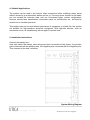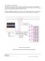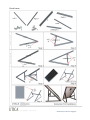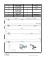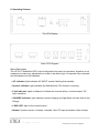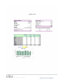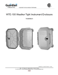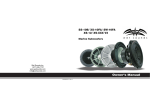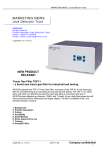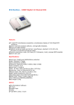
1
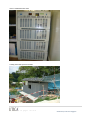
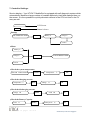
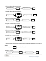
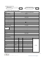
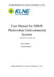
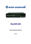
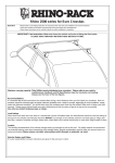
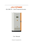
Solar Mobile-Grid Generator User Manual for 3000 Series Mobile Grid 3000-1600 Sales Support Tel: +65 6296 7787 Email: [email protected] 1|P a g e 15 pages in total Produced by UTICA™ Singapore Warning - Risk of high voltages! Thank you for choosing UTICA™– and congratulations on your new, technically high-grade solar powered generator! This instruction manual will help you get to know your new machine. Please read the manual carefully and you will soon be familiar with all the many great features of your new UTICA™ product. Please also take special note of the safety rules. Do not remove the cover on the MobileGrid’s CPU machine or phtovoltaic modules. Incorrect operation and work performed incorrectly can cause serious injury and damage. UTICA™ MobileGrid design and specification has taken into account the operator's safety, strictly in accordance with our manual operation. Any improper installation may cause personal injury. MobileGrid’s CPU with high loads does not allow hot plug or switch repeatedly, especially with a compressor-type loads (such as motors, refrigerators, air conditioners, etc.). 1. Terms of Use This system in the strict production control and precision testing, during the warranty period of two years (maintenance service contract up to10 years system warranty), under normal use of any natural damage, repair is free, but if any of the following circumstances, the warranty will be void: • Without permission repairs (only by our certified technicians). • Any additions or modifications. 2|P a g e 15 pages in total Produced by UTICA™ Singapore • Incorrect operation or use. • Not in accordance with the user manual for cleaning or maintenance. • Abnormal environmental conditions resulting in damage. • The deliberate destruction/ damage. • Natural disasters caused damage. 2. Operation Safety In any case, the operation, cleaning or maintenance, must comply with the following provisions, if violated, the UTICA™ will not be responsible. • Not in a volatile gas or combustible environment. • Do not use positive and negative pole at reverse. • Never remove the MobileGrid’s CPU cover or touch the internal components. • Do not replacing parts of the equipment. 3. Operating Instructions • Installation by UTICA professionals or by the appointed integrator. • Verify that the same load voltage, load power is not greater than the rated load. • Do not allow the liquid into the interior of the machine, do not use wet cleaning machine. • For normal operating environment for the system. • System operating environment should be well ventilated, temperature range -10 degrees to 45 degrees, away from the fire, not direct sunlight, not in the condensation, dust environments. • When the system boots, if the input voltage is too low, the machine is protected and displayed insufficient voltage. • Minors should not use this product. 3|P a g e 15 pages in total Produced by UTICA™ Singapore • Verify that the system reliable grounding, wire size should meet the safety conditions of use, cables as short as possible. • 80% of the load is better. Pay attention to Inductive load started. • Boot sequence: Turn on DC power, and then turn on the system, and finally open the load, shutdown sequence: off load, shut down the CPU, turn off the DC power supply. • Off Mode: Off mode and switch the same way as mobile phone, hold down the switch, and so heard the "beep" (about 3 seconds), then the machine start, began to work; press "power" button for 3 seconds, the system will be shut down. 4. Product Features • MobileGrid’s CPU control systems, intelligent pure sine wave output. • The system uses frequency inverter transform mode, soft-switch technology, high-performance MCU control, digital and analog hybrid technology a boost with the completion of the advanced SPWM waveform modulation circuit, high efficiency, high reliability. • System output can load all types of single-phase equipment such as motors, air conditioning, electric drill, fluorescent lamps, television, computers, fans, refrigerators and other appliances, communications equipment, industrial equipment. • One-Touch Intelligent switch design to facilitate the operation. • Excellent output short circuit protection design. • Ability to start to resist high current load. • Overload protection designed to protect the safe operation of the system, when the load is greater than 5% to 20%, about 30 seconds the system will automatically shut down when the load is greater than 20% of the system will automatically and immediately shut down. • DC power supply is less than 15% of the nominal value, the system will automatically shut down. • AC input with this system, when the system voltage protection, the system will automatically switch to conventional electricity, to ensure supply security. 4|P a g e 15 pages in total Produced by UTICA™ Singapore 4. Suitable Applications The system can be used in the homes, villas construction sites, buildings, ships, areas without electricity, the transmitter station and so on. Pure sine wave inverter for all loads, you can access the inductive load, such as: fluorescent lights, motors, refrigerators, freezers, electric fans, transformers, microwave ovens, air conditioners, etc., but must be careful not to overload operation. This product can not be used without permission of equipment to sustain life, the system not suitable for high-precision electronic equipment. With high-risk devices, such as microwave ovens, air-conditioning, reboot again 5 minutes later. 5. Installation Instructions Connect the battery box: Host cells within the battery case wiring has been connected at the factory, the positive pole connected with the positive pole, the negative pole connected with the negative pole, Then connect to the host, as below: System Wiring Diagram 5|P a g e 15 pages in total Produced by UTICA™ Singapore The installation of solar panels: Tilt angle of solar panels, please refer to the local latitude, tilt angle is the local latitude; The southern hemisphere, solar panels toward the north of users, users will be solar panels on the northern hemisphere towards the south; UTICA™ MobileGrid 3000-1600 is DC 48V, 48V system will be four solar panels connected in series, and then each group will be connected in parallel to the system. Connect to PV CPU system 48V system, photovoltaic panels wiring sample diagram 6|P a g e 15 pages in total Produced by UTICA™ Singapore Panel frame : 7|P a g e 15 pages in total Produced by UTICA™ Singapore Name A B C D E F Stander 1060X35X35 MM Thick:3 MM 800X35X35 MM Thick:3 MM 300X35X35 MM Thick:3 MM 670X35X 35MM Thick:3 MM M5,4.8 M5,4.8 Quantity Illustration Contain Left & Right Contain Left & Right 2 2 2 1 12 12 618MM Butterfly Nut Butterfly Bolt 134MM 280.5MM 926MM 30MM/ 5MM 409MM 251.5MM MM 283MM 150MM 12MM 646MM MM M5 M5 8|P a g e 15 pages in total Produced by UTICA™ Singapore 6. Operating Scheme: The CPU Display Back CPU Diagram Status Description The UTICA™ MobileGrid CPU is pre-configured to be ready for operation, therefore is not necessary to make any adjustments in order to be able to get it to operate fully automatic and feed power into the batteries. • AC indicator: light indicates AC INPUT normal, flashing that standby. • Inverter indicator: light indicates the MobileGrid’s CPU inverter is working. • Fault indicator: lights or flashes to indicate the inverter failure, overload output, DC input exception. • CHARGE indicator: light indicates normal charging, the light does not flash that do not Charge. • LOAD LED: light on the normal output. • Buzzer: System normal, no beeps, overload, fault, DC input anomalies, there is beep. 9|P a g e 15 pages in total Produced by UTICA™ Singapore UTICA™ MobileGrid 3000-1600 1.6kWp photovoltaic powered modules 10 | P a g e 15 pages in total Produced by UTICA™ Singapore 7. Controller Settings: Service display – Your UTICA™ MobileGrid is equipped with self diagnostic system which automatically identifies a large number of possible defects by itself and displays them on the screen. It is thus possible to quickly ascertain defects in the CPU unit and in the PV array as well. LCD Screen Button is down ·Startup SOLAR REGULATOR OK Battery V Charge A Load A ·Menu Battery V Charge A MENU SOLAR REGULATOR Load A ·Check the system temperature SOLAR REGULATOR MENU Temperature OK ℃ ·Check the charging current Temperature ℃ MENU Charge OK Ah ·Check the discharging current Charge Ah MENU Load Ah OK ·Check the Battery Capacity Load Ah MENU Battery SOC % OK 11 | P a g e 15 pages in total Produced by UTICA™ Singapore ·Check the charge-off voltage of battery Battery SOC % Charge off V MENU OK ·Setup the Charge-off voltage of Battery Charge off V Charge off V OK ·Check the load-off voltage of loads Charge off V MENU Load off V OK ·Setup the Load-off Voltage of Loads Load off V Load off V OK ·Check the load-on voltage of loads Load off V MENU Load on V OK ·Setup the load-on voltage of loads Load on V Load on V OK ·Adjust Charge-off voltage of Battery, Load-off Voltage of loads and Load-on Voltage of loads into the defaults Press down MENU for more than 5 seconds ·Startup for over-loads Overload Reduce quantity in loads Reset SOLAR REGULATOR OK 12 | P a g e 15 pages in total Produced by UTICA™ Singapore ·Startup for short circuit Short circuit 8. Remove malfunction Reset SOLAR REGULATOR OK Technical & Performance Data UTICA™ PV MobileGrid 30001600 Model Output capacity 3KVA Output waveform Pure Sine Wave Voltage Accuracy 220V±3% Frequency Accuracy 50HZ±3HZ Overload 120%,30s Overvoltage Protection >58V Undervoltage Protection <40V Efficiency >90% Operating Temperature -5 - 55℃ Operating Humidity 0-90% Operating Altitude 0-3,000m Electricity Switching Time CPU <5ms Size 555X500X200MM Weight 25Kg Battery Case Size 555X500X300MM Solar Panels Power 1600WP Solar Panel Size 1050 x 670 x 30mm Battery 48V270AH Controller System 48V/40A PV Inverter 3000W/48V Load Reference: Name Of Load (Est.) Power(W) Quantity Working Time Per Day (H) Color TV 65W 1 8 Satellite TV Receivers 25W 1 8 LCD Computer 100W 2 6 Energy-saving Lamp 11W 2 5 Electrograph 100W 1 2 Printer 30W 1 1 Fan 50W 1 4 Washing Machine 300W 1 1 Rice Cooker 300W 1 1 Water Pump 200W 1 1 DVD 50W 1 2 Air-condition 1000W 1 1 Working Days 3 Days 13 | P a g e 15 pages in total Produced by UTICA™ Singapore 14 | P a g e 15 pages in total Produced by UTICA™ Singapore Common Faults and Diagnosis Item 1 2 3 4 Common faults Approach Shutdown immediately after boot Confirm the input DC voltage is within the normal range. (Eg: 1000W input DC voltage range of the system 20VDC-27.5VDC) shutdown immediately after Load ① Confirm the input DC voltage is correct. ② sure the load is overloaded Can not boot ①Confirm the input DC voltage is connected correctly. ②Booting method is correct. Can not shut down ①Shutdown method is correct ②Press the shutdown button 3-5 seconds. Remarks ① using the system before you read the instructions ② After wiring, check to confirm correct before turning on power. ③ long load, the machine may have a fever, and hot air blown out. Updated 28th July 2011 – specification is subjected to UTICA™ changes and terms & conditions. 10 years warranty is based on maintenance schedule/ service agreement from Utica Energy Pte Ltd. Technical Support: +65 62967780. 15 | P a g e 15 pages in total Produced by UTICA™ Singapore