1
ControlLogix
SynchLink Module
1756-SYNCH
User Manual
Important User Information
Because of the variety of uses for the products described in this
publication, those responsible for the application and use of these
products must satisfy themselves that all necessary steps have been
taken to assure that each application and use meets all performance
and safety requirements, including any applicable laws, regulations,
codes and standards. In no event will Allen-Bradley be responsible or
liable for indirect or consequential damage resulting from the use or
application of these products.
Any illustrations, charts, sample programs, and layout examples
shown in this publication are intended solely for purposes of
example. Since there are many variables and requirements associated
with any particular installation, Allen-Bradley does not assume
responsibility or liability (to include intellectual property liability) for
actual use based upon the examples shown in this publication.
Allen-Bradley publication SGI-1.1, Safety Guidelines for the
Application, Installation and Maintenance of Solid-State Control
(available from your local Allen-Bradley office), describes some
important differences between solid-state equipment and
electromechanical devices that should be taken into consideration
when applying products such as those described in this publication.
Reproduction of the contents of this copyrighted publication, in whole
or part, without written permission of Rockwell Automation, is
prohibited.
Throughout this publication, notes may be used to make you aware of
safety considerations. The following annotations and their
accompanying statements help you to identify a potential hazard,
avoid a potential hazard, and recognize the consequences of a
potential hazard:
WARNING
!
ATTENTION
!
IMPORTANT
Identifies information about practices or
circumstances that can cause an explosion in a
hazardous environment, which may lead to personal
injury or death, property damage, or economic loss.
Identifies information about practices or
circumstances that can lead to personal injury or
death, property damage, or economic loss.
Identifies information that is critical for successful
application and understanding of the product.
ATTENTION
!
Environment and Enclosure
This equipment is intended for use in a Pollution
Degree 2 industrial environment, in overvoltage
Category II applications (as defined in IEC
publication 60664-1), at altitudes up to 2000 meters
without derating.
This equipment is considered Group 1, Class A
industrial equipment according to IEC/CISPR
Publication 11. Without appropriate precautions,
there may be potential difficulties ensuring
electromagnetic compatibility in other environments
due to conducted as well as radiated disturbance.
This equipment is supplied as "open type"
equipment. It must be mounted within an enclosure
that is suitably designed for those specific
environmental conditions that will be present and
appropriately designed to prevent personal injury
resulting from accessibility to live parts. The interior
of the enclosure must be accessible only by the use
of a tool. Subsequent sections of this publication
may contain additional information regarding
specific enclosure type ratings that are required to
comply with certain product safety certifications.
See NEMA Standards publication 250 and IEC
publication 60529, as applicable, for explanations of
the degrees of protection provided by different types
of enclosure. Also, see the appropriate sections in
this publication, as well as the Allen-Bradley
publication 1770-4.1 ("Industrial Automation Wiring
and Grounding Guidelines"), for additional
installation requirements pertaining to this
equipment.
Rockwell Automation
Support
Rockwell Automation offers support services worldwide, with over 75
sales/support offices, 512 authorized distributors and 260 authorized
systems integrators located throughout the United States alone, as well
as Rockwell Automation representatives in every major country in the
world.
Local Product Support
Contact your local Rockwell Automation representative for:
• sales and order support
• product technical training
• warranty support
• support service agreements
Technical Product Assistance
If you need to contact Rockwell Automation for technical assistance,
please review the troubleshooting information first. If the problem
persists, then call your local Rockwell Automation representative.
Your Questions or Comments on this Manual
If you find a problem with this manual, please notify us of it on the
enclosed How Are We Doing form.
Allen-Bradley is a trademark of Rockwell Automation
ControlLogix is a trademark of Rockwell Automation
SynchLink is a trademark of Rockwell Automation
Preface
About This Preface
This preface describes how to use this manual. The following table
describes what this preface contains and its location.
For information about:
Who Should Use
This Manual
See page:
Who Should Use This Manual
Preface-1
Purpose of This Manual
Preface-1
Related Products and Documentation
Preface-4
You must be able to program and operate an Allen-Bradley
ControlLogix™ Logix controller and ControlLogix I/O modules to
efficiently use your SynchLink™ module.
We assume that you know how to do this in this manual. If you do
not, refer to Related Documentation, before you attempt to use this
module.
IMPORTANT
SynchLink should be used in conjunction with a
standard control network, such as ControlNet or
Ethernet. A standard network is used for general
control interlocking and transfer of diagnostic data
across the system.
SynchLink does not function as a standard control
network (e.g. it broadcasts data in a unidirectional
manner).
Purpose of This Manual
1
This manual describes how to install, configure, and troubleshoot
your ControlLogix SynchLink module.
Publication 1756-UM521A-EN-P - August 2001
Preface
2
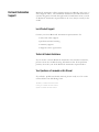
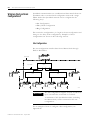
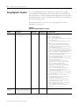
What This Manual Contains
This user manual contains the following sections:
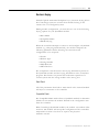
Chapter 1 - What is the
1756-SYNCH module?
Description of the SynchLink module
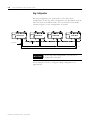
Chapter 2 - Time Synchronization in the
ControlLogix System
Description of how the SynchLink module
synchronizes time in the ControlLogix system
Chapter 3 - SynchLink Module
Features
Description of the SynchLink module
certifications and general features
Chapter 4 - Installing the SynchLink
Module
Description of how to install the SynchLink
module and connect the fiber optic cable
Chapter 5 - Configuring the
SynchLink Module
Description of how to configure the
SynchLink module with RSLogix 5000
Chapter 6 - Troubleshooting the
SynchLink Module
Description of how to troubleshoot
the SynchLink module
SynchLink
LINK
COMM
LINK
SYNC
OK
Publication 1756-UM521A-EN-P - August 2001
Preface
Appendix A - Specifications
Listing of the SynchLink module
specifications
Appendix C - Configuring the
Daisy Chain Configuration
Example of how to configure the
SynchLink Daisy Chain Configuration
Appendix B - Configuring the Star
Configuration
Example of how to configure the
SynchLink Star Configuration
Appendix D - Configuring the Ring
Configuration
Example of how to configure the
SynchLink Ring Configuration
Glossary
Glossary of terms used with the
SynchLink module
3
Appendix E - Software
Configuration Tags
Complete list of all the input and
output data tags
Index
Index of terms and concepts explained
thoughout this user manual
Publication 1756-UM521A-EN-P - August 2001
Preface
4
Related Products and
Documentation
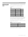
The following table lists related ControlLogix products and
documentation:
Table Preface.A
Related Documentation
Catalog
number:
Document title:
Pub. number:
1756-SYNCH
ControlLogix SynchLink Module Installation
Instructions
1756-IN575
1756-A4, -A7,
-A10, -A13
ControlLogix Chassis Installation Instructions
1756-IN080B
1756-PA72,
-PB72
ControlLogix Power Supply Installation Instructions
1756-5.67
1756-PA75,
-PB75
ControlLogix Power Supply Installation Instructions
1756-5.78
1756-Series
ControlLogix Module Installation Instructions
(Each module has separate installation document.)
Multiple 1756-IN
numbers
1756-Series
ControlLogix System User Manual
1756-UM001
Multiple
numbers
SynchLink Design Guide
1756-TD008
1751-SLBA
SynchLink Base Block Installation Instructions
1751-IN001
1751-SL4SP
SynchLink 4-port Splitter Block Installation
Instructions
1751-IN002
1751-SLBP
SynchLink Bypass Switch Block Installation
Instructions
1751-IN003
1756-DM
ControlLogix Drive Module Installation Instructions
1756-IN577
1756-DM
ControlLogix Drive Module User Manual
1756-UM522
PowerFlex 700S User Manual
20D-UM001
If you need more information on these products, contact your local
Allen-Bradley integrator or sales office for assistance. For more
information on the documentation, refer to the Allen-Bradley
Publication Index, publication SD499.
Publication 1756-UM521A-EN-P - August 2001
Table of Contents
Chapter 1
What is the 1756-SYNCH module? What is the ControlLogix SynchLink Module? . . . . . . . . . . . 1-1
What Data Does the SynchLink Module Transfer? . . . . .
Why Synchronize Time Between Chassis? . . . . . . . . . . .
What Are Some of the Features Available On the
ControlLogix SynchLink Module? . . . . . . . . . . . . . . . . .
Connecting a SynchLink Module to a SynchLink System . . .
Physical Features of the ControlLogix SynchLink Module
Using Module Identification and Status Information . . . . . .
Preventing Electrostatic Discharge . . . . . . . . . . . . . . . . . . .
Removal and Insertion Under Power . . . . . . . . . . . . . . . . .
Chapter Summary and What’s Next . . . . . . . . . . . . . . . . . .
1-1
1-2
1-2
1-3
1-4
1-5
1-7
1-7
1-8
Chapter 2
Time Synchronization in the
ControlLogix System
Using the Coordinated System Time (CST) . . . . . . . . . . . .
Time Synchronization in a Distributed Control System . . .
Time Synchronization in the SynchLink System . . . . . . . .
SynchLink Node Clock . . . . . . . . . . . . . . . . . . . . . . . .
How Do the CST Clock and SynchLink Node Clock Work
Together? . . . . . . . . . . . . . . . . . . . . . . . . . . . . . . . . . . . .
Configuring Time Mastership Functionality. . . . . . . . . . . .
What are the SynchLink Configurations?. . . . . . . . . . . . . .
Star Configuration . . . . . . . . . . . . . . . . . . . . . . . . . . .
Daisy Chain Configuration . . . . . . . . . . . . . . . . . . . . .
Ring Configuration. . . . . . . . . . . . . . . . . . . . . . . . . . .
Cable Usage . . . . . . . . . . . . . . . . . . . . . . . . . . . . . . .
Chapter Summary and What’s Next . . . . . . . . . . . . . . . . .
.
.
.
.
2-2
2-2
2-2
2-3
.
.
.
.
.
.
.
.
2-5
2-6
2-8
2-8
2-9
2-10
2-11
2-11
.
.
.
.
.
.
.
.
.
.
.
.
.
.
.
3-1
3-2
3-3
3-3
3-3
3-4
3-4
3-4
3-5
3-9
3-11
3-13
3-14
3-16
3-16
Chapter 3
SynchLink Module Features
i
General Module Features. . . . . . . . . . . . . . . . . .
Removal and Insertion Under Power (RIUP) .
Module Fault Reporting . . . . . . . . . . . . . . . .
Fully Software Configurable . . . . . . . . . . . . .
LED Status Information. . . . . . . . . . . . . . . . .
Class I Division 2 Certification . . . . . . . . . . .
Agency Certification . . . . . . . . . . . . . . . . . . .
Configurable Module Features . . . . . . . . . . . . . .
Communications Format. . . . . . . . . . . . . . . .
Electronic Keying. . . . . . . . . . . . . . . . . . . . .
Requested Packet Interval . . . . . . . . . . . . . .
SynchLink Transmitted Axes. . . . . . . . . . . . .
Transmitted Direct Words. . . . . . . . . . . . . . .
CST and SynchLink Mastership . . . . . . . . . . .
Chapter Summary and What’s Next . . . . . . . . . .
.
.
.
.
.
.
.
.
.
.
.
.
.
.
.
.
.
.
.
.
.
.
.
.
.
.
.
.
.
.
.
.
.
.
.
.
.
.
.
.
.
.
.
.
.
.
.
.
.
.
.
.
.
.
.
.
.
.
.
.
.
.
.
.
.
.
.
.
.
.
.
.
.
.
.
.
.
.
.
.
.
.
.
.
.
.
.
.
.
.
.
.
.
.
.
.
.
.
.
.
.
.
.
.
.
Publication 1756-UM521A-EN-P - August 2001
Table of Contents
ii
Chapter 4
Installing the SynchLink Module
Noting the Power Requirements . .
Installing the Module. . . . . . . . . . .
Connecting the Fiber Optic Cable .
Removing the Module . . . . . . . . . .
Chapter Summary and What’s Next
.
.
.
.
.
.
.
.
.
.
.
.
.
.
.
.
.
.
.
.
.
.
.
.
.
.
.
.
.
.
.
.
.
.
.
.
.
.
.
.
.
.
.
.
.
.
.
.
.
.
.
.
.
.
.
.
.
.
.
.
.
.
.
.
.
.
.
.
.
.
.
.
.
.
.
.
.
.
.
.
.
.
.
.
.
.
.
.
.
.
4-1
4-2
4-3
4-4
4-5
Chapter 5
Configuring the SynchLink Module Overview of the Configuration Process . . . . . . . . . . . . . . . 5-2
Choose a SynchLink Configuration. . . . . . . . . . . . . . . . . . . 5-3
Star Configuration. . . . . . . . . . . . . . . . . . . . . . . . . . . . . 5-3
Daisy Chain Configuration.. . . . . . . . . . . . . . . . . . . . . . 5-3
Ring Configuration. . . . . . . . . . . . . . . . . . . . . . . . . . . . 5-3
Create a New RSLogix 5000 Project. . . . . . . . . . . . . . . . 5-4
Add a SynchLink Module . . . . . . . . . . . . . . . . . . . . . . . 5-5
Configure the SynchLink Module . . . . . . . . . . . . . . . . . 5-6
Download Configuration . . . . . . . . . . . . . . . . . . . . . . . 5-8
Changing Configuration After Module Operation Has Begun 5-9
Chapter Summary and What’s Next . . . . . . . . . . . . . . . . . . 5-10
Chapter 6
Troubleshooting the
SynchLink Module
Publication 1756-UM521A-EN-P - August 2001
Using the Status Indicators. . . . . . . . . . . . . . . . .
Using RSLogix 5000 to Troubleshoot the Module
Determining Fault Type . . . . . . . . . . . . . . . .
Using Diagnostic Counters. . . . . . . . . . . . . . . . .
Message Instructions . . . . . . . . . . . . . . . . . .
Message Configuration . . . . . . . . . . . . . . . . .
Retrieving and Resetting Diagnostic Counters . . .
Chapter Summary and What’s Next . . . . . . . . . .
.
.
.
.
.
.
.
.
.
.
.
.
.
.
.
.
.
.
.
.
.
.
.
.
.
.
.
.
.
.
.
.
.
.
.
.
.
.
.
.
.
.
.
.
.
.
.
.
.
.
.
.
.
.
.
.
.
.
.
.
.
.
.
.
6-1
6-3
6-5
6-6
6-7
6-8
6-11
6-11
Table of Contents
iii
Appendix A
Specifications
Appendix B
Configuring the Star Configuration Using Remote Axis Control . . . . . . . . . . . . . . . . . . . . . . . . B-2
Configure Time Master Chassis - Master Node . . . . . . . . B-2
Configure Time Slave Chassis - End Node. . . . . . . . . . . B-8
Configure Time Slave Chassis - End Node. . . . . . . . . . B-13
Appendix C
Configuring the Daisy Chain
Configuration
Configure Time Master Chassis - Master Node . . . . . . . . C-2
Configure Time Slave Chassis - Center Node . . . . . . . . . C-7
Configure Time Slave Chassis - End Node. . . . . . . . . . C-12
Appendix D
Configuring the Ring Configuration
Configure Time Master Chassis - Master Node . . . . . . . . D-2
Configure Time Slave Chassis - Center Node . . . . . . . . . D-7
Configure Time Slave Chassis - End Node. . . . . . . . . . D-12
Appendix E
Software Configuration Tags
Accessing the Tags . . . . . . . . . . . . . . . . . . . . . . . . . . . . . . E-2
Input Data Tags . . . . . . . . . . . . . . . . . . . . . . . . . . . . . . . . E-3
Output Data Tags . . . . . . . . . . . . . . . . . . . . . . . . . . . . . . . E-4
Glossary
Index
Publication 1756-UM521A-EN-P - August 2001
Table of Contents
iv
Publication 1756-UM521A-EN-P - August 2001
Chapter
1
What is the 1756-SYNCH module?
This chapter describes the ControlLogix SynchLink module. It also
describes ìwhat you must know and do before using the SynchLink
module.
For information on:
What is the ControlLogix
SynchLink Module?
See page:
What is the ControlLogix SynchLink
Module?
1-1
Connecting a SynchLink Module to a
SynchLink System
1-3
Using Module Identification and Status
Information
1-5
Preventing Electrostatic Discharge
1-7
Removal and Insertion Under Power
1-7
Chapter Summary and What’s Next
1-8
A ControlLogix SynchLink module, through the use of fiber optic
communication technology, allows you to implement:
• time synchronization
• distributed motion control
• coordinated drive control
based on the ControlLogix and PowerFlex 700S platforms. In
distributed control system, the SynchLink module broadcasts reference
data and synchronizes time from a single ControlLogix chassis to
multiple other chassis at a high speed.
What Data Does the SynchLink Module Transfer?
The SynchLink module transfers multiple types of reference data
between chassis, including:
• Produced axis data for chassis to chassis remote axis control
• High speed drive reference data for chassis to drive control
• General control information that requires transfer at a high
speed and in a synchronized manner
1
Publication 1756-UM521A-EN-P - August 2001
1-2
What is the 1756-SYNCH module?
Why Synchronize Time Between Chassis?
In synchronizing time between chassis, the SynchLink module allows
you to:
• share motion data from chassis to chassis because a consistent
time reference is available among chassis for interpolation of
velocity and position data.
• timestamp I/O in multiple chassis and have a common time
reference with which to compare the timestamps.
For more information on how the SynchLink module impacts the time
references between ControlLogix chassis, see Chapter 2, Time
Synchronization in the ControlLogix System.
What Are Some of the Features Available On the ControlLogix
SynchLink Module?
The following are some of the features available on the ControlLogix
SynchLink module:
• Support of multiple SynchLink system configurations - Star, daisy
chain and ring
For more information on these functions, see Chapter 2, Time
Synchronization in the ControlLogix System For more
information on how to configure the module with RSLogix 5000,
see Chapter 5, Configuring the SynchLink Module.
• Removal and insertion under power (RIUP) - This system feature
allows you to remove and insert the module while power is
applied. For more information on RIUP, see page 1-7.
• Communication of remote axis data in a timely and
deterministic manner
• Communication of direct and buffered data
• Class I Division 2, UL, CSA, and CE Agency Certification
Publication 1756-UM521A-EN-P - August 2001
What is the 1756-SYNCH module?
Connecting a SynchLink
Module to a SynchLink
System
1-3
ControlLogix SynchLink modules mount in a ControlLogix chassis and
connects to other SynchLink node through a fiber optic cable system.
For more information on the available fiber optic cables,
see Table 1.A.
Table 1.A
Fiber Optic Cables Available with the 1756-SYNCH Module
Catalog number:
Cable length
Cables per box:
1403-CF001
1m (3.28ft)
2
1403-CF003
3m (9.84ft)
2
1403-CF005
5m (16.4ft)
2
1403-CF010
10m (32.8ft)
1
1403-CF020
20m (65.6ft)
1
1403-CF050
50m (164ft)
1
1403-CF100
100m (328ft)
1
1403-CF250
250m (820ft)
1
When you install the SynchLink module in a Star Configuration, you
need to use hubs as well as fiber optic cables. A hub is a combination
of one base block with up to four splitter blocks. A bypass switch
block is also available for use in the daisy chain configuration. For
more information on the Star Configuration, see page 2-8.
For more information the hub components available for use with the
SynchLink module, see Table 1.B
Table 1.B
Hub Components Available with the 1756-SYNCH Module
Catalog Number:
Hub Type:
1751-SLBA
SynchLink Fiber Base Block
1751-SL4SP
SynchLink Fiber 4-Port Splitter Block
1751-SLBP
SynchLink Fiber Bypass Switch Block
For more information on SynchLink fiber optic cable systems, see The
SynchLink Design Guide, publication 1756-TD008.
Publication 1756-UM521A-EN-P - August 2001
1-4
What is the 1756-SYNCH module?
Before you install and use your module you should have already:
• installed and grounded a 1756 chassis and power supply. For
more information, refer to the publications listed in Table 1.C.
Table 1.C
Chassis and Power Supply Documentation
Catalog
number:
Document title:
Pub. number:
1756-A4, -A7,
-A10, -A13
ControlLogix Chassis Installation Instructions
1756-IN080
1756-PA72,
-PB72
ControlLogix Power Supply Installation Instructions
1756-5.67
1756-PA75,
-PB75
ControlLogix Power Supply Installation Instructions
1756-5.78
1756-PA75R/A,
-PB75R/A
ControlLogix Redundant Power Supply Installation
Instructions
1756-IN573
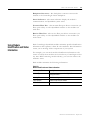
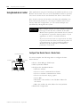
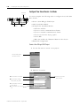
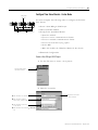
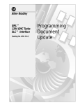
Physical Features of the ControlLogix SynchLink Module
Module side view
Module front view
LINK
COMM
LINK
SYNC
OK
Backplane
Connector- Interface
to the ControlLogix
system backplane
Status
Indicators
42744
Transmit
Fiber Port
Publication 1756-UM521A-EN-P - August 2001
Receive
Fiber Port
What is the 1756-SYNCH module?
1-5
Backplane Connector - The backplane connector connects the
module to the ControlLogix chassis backplane.
Status Indicators - The status indicators display the module’s
communications and SynchLink system status.
Transmit Fiber Port - The transmit fiber port allows connection (via
fiber optic cables) to other SynchLink modules so the module can
send data.
Receive Fiber Port - The receive fiber port allows connection (via
fiber optic cables) to other SynchLink modules so the module can
receive data.
Using Module
Identification and Status
Information
Each ControlLogix SynchLink module maintains specific identification
information that separates it from all other modules. This information
assists you in tracking all the components of your system.
For example, you can track module identification information to be
aware of exactly what modules are located in any ControlLogix rack at
any time. While retrieving module identity, you can also retrieve the
module’s status.
Each module maintains the following information:
Table 1.D
Module Identification and Status Information
Module Identification:
Description:
Product Type
Module’s product type, such as Digital I/O or
Analog I/O module
Catalog Code
Module’s catalog number
Major Revision
Module’s major revision number
Minor Revision
Module’s minor revision number
Publication 1756-UM521A-EN-P - August 2001
1-6
What is the 1756-SYNCH module?
Table 1.D
Module Identification and Status Information
Module Identification:
Description:
Status
Module’s status. Returns the following information:
• Controller ownership (if any)
• Whether module has been configured
• Device Specific Status, such as:
– Self-Test
– Flash update in progress
– Communications fault
– Not owned (outputs in program mode)
– Internal fault (need flash update)
– Run mode
• Minor recoverable fault
• Minor unrecoverable fault
• Major recoverable fault
• Major unrecoverable fault
Vendor ID
Module manufacturer vendor, for example Allen-Bradley
Serial Number
Module serial number
Length of ASCII Text String
Number of characters in module’s text string
ASCII Text String
Number of characters in module’s text string
IMPORTANT
Publication 1756-UM521A-EN-P - August 2001
You must use the WHO service in the RSLinx
software to retrieve this information. For more
information on how to retrieve module identification
information, see the RSLinx online help.
What is the 1756-SYNCH module?
Preventing Electrostatic
Discharge
This module is sensitive to electrostatic discharge.
ATTENTION
!
Removal and Insertion
Under Power
1-7
Preventing Electrostatic Discharge
This equipment is sensitive to electrostatic discharge,
which can cause internal damage and affect normal
operation. Follow these guidelines when you handle
this equipment:
• Touch a grounded object to discharge potential
static.
• Wear an approved grounding wriststrap.
• Do not touch connectors or pins on component
boards.
• Do not touch circuit components inside the
equipment.
• If available, use a static-safe workstation.
• When not in use, store the equipment in
appropriate static-safe packaging.
These modules are designed to be installed or removed while chassis
power is applied.
WARNING
!
When you insert or remove the module while
backplane power is on, an electrical arc can occur.
This could cause an explosion in hazardous location
installations. Be sure that power is removed or the
area is nonhazardous before proceeding.
Repeated electrical arcing causes excessive wear to contacts on both
the module and its mating connector. Worn contacts may create
electrical resistance that can affect module operation.
Publication 1756-UM521A-EN-P - August 2001
1-8
What is the 1756-SYNCH module?
Chapter Summary and
What’s Next
Publication 1756-UM521A-EN-P - August 2001
In this chapter, you learned about the ControlLogix SynchLink
module. For information about Time Synchronization in the
ControlLogix System, see Chapter 2.
Chapter
2
Time Synchronization in the
ControlLogix System
This chapter describes how the ControlLogix SynchLink module fits in
the ControlLogix system.
For information on:
See page:
Using the Coordinated System Time (CST)
2-2
Time Synchronization in a Distributed
Control System
2-2
Time Synchronization in the SynchLink
System
2-2
How Do the CST Clock and SynchLink Node
Clock Work Together?
2-5
What are the SynchLink Configurations?
2-8
Chapter Summary and What’s Next
2-11
Before you can fully understand how the SynchLink module can be
used in a distributed ControlLogix system, you should understand
how a ControlLogix application works without SynchLink. See the
ControlLogix System User Manual, publication 1756-UM001 for a
detailed description of the ControlLogix system.
IMPORTANT
1
Part of this chapter describes the differences
between ControlLogix systems that do and do not
use the SynchLink module. In systems that use the
SynchLink module, a Logix controller must reside in
every chassis that contains a SynchLink module.
Publication 1756-UM521A-EN-P - August 2001
2-2
Time Synchronization in the ControlLogix System
Using the Coordinated
System Time (CST)
The Coordinated System Time (CST) is the clocking mechanism used
to achieve time synchronization in a ControlLogix chassis. The
ControlLogix Coordinated System Time (CST) clock is a 64-bit clock
on the backplane of the ControlLogix chassis. It has a 1µS resolution
and is used as the main time reference for all modules plugged into a
chassis backplane.
For more information on how the ControlLogix CST affects the
operation of other ControlLogix products, see the ControlLogix System
User Manual, publication 1756-UM001.
Time Synchronization in a
Distributed Control System
The same CST mechanism described above is also used to
synchronize ControlLogix chassis in a distributed control system. In
such a system, SynchLink transfers the CST value from the CST Master
chassis to CST Slave chassis. Each chassis must be equipped with a
SynchLink module. This distributed control system is identified as a
SynchLink system.
Time Synchronization in the
SynchLink System
Time synchronization within a SynchLink system is required to:
• transfer a CST value from the CST Master chassis to CST Slave
chassis.
• transfer motion and drive control data.
• support time synchronization between ControlLogix chassis and
non-ControlLogix products (e.g. PowerFlex 700S products).
The SynchLink Node Clock is integral to all devices that contain the
SynchLink circuitry. It is the clocking mechanism on the fiber optic
side of the SynchLink system. This clock has a resolution of 1µS.
During system configuration, you establish one SynchLink node clock
as the master system clock on the SynchLink fiber. By design, the
ControlLogix chassis that is configured as the SynchLink master also
acts as the CST master of the system. In this manner, one SynchLink
node acts as a Time Master for the entire system. This chapter gives
more detail on how this functionality is accomplished.
Multiple Rockwell Automation products can be synchronized with
SynchLink. In addition to the SynchLink module, the PowerFlex 700S
and the 1756-DMxxx series products (both used for drive control) also
use SynchLink to achieve drive to drive synchronization. While all of
these products maintain interoperability, not all SynchLink features are
incorporated into every product that uses SynchLink; the 1756-SYNCH
module, however, uses all of the SynchLink features.
Publication 1756-UM521A-EN-P - August 2001
Time Synchronization in the ControlLogix System
2-3
SynchLink Node Clock
The SynchLink node clock is integral to the SynchLink circuit design.
Any product incorporating SynchLink incorporates the SynchLink
node clock as a base-line requirement. The SynchLink node clock has
a 1µS resolution and is synchronized from node to node when the
SynchLink system is configured.
SynchLink uses a Time Master-slave mechanism to achieve time
synchronization. During system configuration, you configure one
SynchLink node as the Time Master and all other nodes as time slaves.
The SynchLink node that is configured as Time Master becomes the
system clock for the entire SynchLink system. As such, the SynchLink
Time Master broadcasts its time reference to the SynchLink Time
Slaves which adjust their node clocks to be in phase with the
master clock.
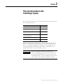
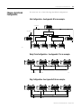
Since SynchLink is a unidirectional, broadcasting mechanism, the
master is always placed at the beginning of a SynchLink system,
regardless of topology, as shown in Figure 2.1.
Figure 2.1
Star Configuration
Daisy Chain Configuration
SynchLink
Time Master
S.L.N.C.
S.L.N.C.
S.L.N.C.
S.L.N.C.
SynchLink
Time Master
SynchLink
Time Slave
SynchLink
Time Slave
42981
Hub
S.L.N.C.
S.L.N.C.
S.L.N.C.
S.L.N.C.
SynchLink
Time Slave
SynchLink
Time Slave
SynchLink
Time Slave
SynchLink
Time Slave
42980
S.L.N.C. = SynchLink Node Clock
Publication 1756-UM521A-EN-P - August 2001
2-4
Time Synchronization in the ControlLogix System
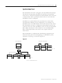
System Synchronization
When a SynchLink system is initialized, the individual SynchLink
nodes power-up at separate times and the individual SynchLink node
clocks begin to count at arbitrary points in time. When this occurs, the
system is not yet synchronized. As the master node clock counts, it
reaches a point where it rolls over and goes back to zero.
When the rollover occurs, the SynchLink master transmits a beacon
signal to the SynchLink time slaves; the beacon is included in the
control field of the transmitted message. When the SynchLink Time
Slave receives the first message with the beacon signal, it begins to
adjust the 1 microsecond time base of its node clock to synchronize
with the master clock. This process can be gradual or immediate,
depending on the product implementation.
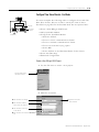
Figure 2.2
Initial Start-Up
Master
Time adjustment
Slave
Beacon
Beacon
Beacon
42982
Synchronized Operation
Master
Slave
42983
After a SynchLink Time Slave is synchronized with the Time Master,
each SynchLink frame that is transmitted serves as a 50µS “tick” (or
mark) used for the periodic adjustment of its clock’s 1µS time base.
This process provides highly accurate results.
Figure 2.3
Beacon signal
synchronizes
SynchLink node
clocks
SynchLink 50 microsecond message frame
serves as a “tick” to keep clocks synchronized
Publication 1756-UM521A-EN-P - August 2001
42984
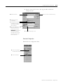
Time Synchronization in the ControlLogix System
How Do the CST Clock and
SynchLink Node Clock
Work Together?
2-5
As stated earlier, the ControlLogix Coordinated System Time clock
(CST) is a 64-bit clock on the ControlLogix backplane. It is used as the
main time reference for all modules plugged into a ControlLogix
chassis. The SynchLink node clock is used to establish the time
reference on the SynchLink fiber.
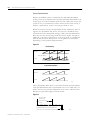
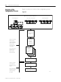
Figure 2.4 illustrates how the SynchLink node clock and the CST time
reference are coordinated in a system. In this example, the SynchLink
modules in chassis A & B synchronize the CST clock in chassis B with
the CST reference in chassis A.
Chassis A is the Time Master for the system. When the SynchLink
module strobes the beacon signal onto the fiber optic link, it also
transmits the CST time reference value that tells the downstream node
what time it is as the beacon occurs. The downstream chassis receives
the CST time reference and synchronizes its time with the CST
reference value on the beacon signal.
Figure 2.4
Chassis A
64-bit clock
Coordinated System Time
Chassis B
Coordinated System Time
1756-SYNCH
SynchLink Node Clock
1756-SYNCH
Clock
SynchLink beacon over
the fiber optic link
Publication 1756-UM521A-EN-P - August 2001
2-6
Time Synchronization in the ControlLogix System
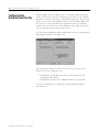
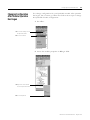
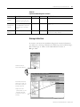
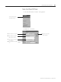
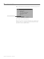
Configuring Time
Mastership Functionality
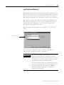
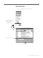
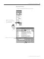
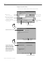
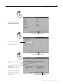
In the example shown in Figure 2.4, you configure time mastership
for the system when initially configuring the module. In the “Module
Properties” software screens, the “Time Mastership” tab offers you the
option to select the 1756-SYNCH module as the CST Time Master for
the chassis, or, the Time Master on SynchLink. For any SynchLink
system, there can only be one Time Master for the entire system. All
other connected devices must be time slaves.
Use the following RSLogix 5000 configuration screen to establish time
mastership in Chassis A of Figure 2.4:
By checking the Make this module the Coordinated System Time
Master for the SynchLink box, you:
• establish the SynchLink node clock on this module as the
SynchLink Time Master.
• establish the chassis as the CST Time Master on SynchLink.
For more information on configuring your SynchLink modules,
see Chapter 5.
Publication 1756-UM521A-EN-P - August 2001
Time Synchronization in the ControlLogix System
2-7
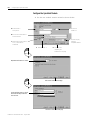
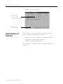
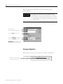
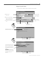
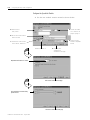
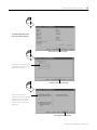
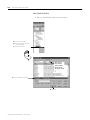
You use the following RSLogix 5000 configuration screen to establish
a Time Slave in Chassis B of Figure 2.4:
By checking the Make this module the Coordinated System Time
Master for the chassis box, you:
• establish the SynchLink module as a Time Slave on SynchLink.
• establish the module as the CST Time Master of the local chassis.
The selection shown above (i.e. Make this module the Coordinated
System Time Master for the chassis) is also optional for the CST Time
Master chassis. If this selection is NOT selected in the Time Master
chassis, another module on the backplane MUST be selected as the
CST backplane master in order to allow the master chassis to have a
CST reference value. Other modules that could be CST time masters
are ControlLogix controllers and other 1756-SYNCH modules. Only
one CST master can exist in a chassis at one time.
For more information on configuring your SynchLink modules,
see Chapter 5.
Publication 1756-UM521A-EN-P - August 2001
2-8
Time Synchronization in the ControlLogix System
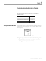
What are the SynchLink
Configurations?
SynchLink communications are a unidirectional data transfer from one
SynchLink node to another. Each configuration starts with a single
Master Node. The SynchLink network can be configured in the
following ways.
• Star Configuration
• Daisy Chain Configuration
• Ring Configuration
Do not mix the configurations (i.e. begin in the star configuration and
change to the daisy chain configuration). Examples of these
configurations are shown in the following sections.
Star Configuration
The star configuration transfers data from a Master Node through
Hubs to End Nodes.
ControlNet
Master Node
Hub
SynchLink
Hub
End Node
End Node
Hub
End Node
End Node
End Node
End Node
42747
IMPORTANT
The star configuration supports 2 layers of hubs with
up to 16 end nodes connected to each hub.
A maximum of 257 SynchLink modules (including
the Master Node) can be connected in the star
configuration.
For an example of how to configure a Star configuration, see
Appendix B.
Publication 1756-UM521A-EN-P - August 2001
Time Synchronization in the ControlLogix System
2-9
Daisy Chain Configuration
In the daisy chain configuration, the SynchLink network starts at the
Master Node and ends at an End Node. You can include Center Nodes
(shown in Figure ) in the configuration as needed.
Master Node
SynchLink
Center Node
Center Node
End Node
ControlNet
42746
IMPORTANT
In the daisy chain configuration, you can use a
maximum of 10 nodes, including the master and
end nodes.
Also, the only difference between Center and End
Nodes is their physical location.
In the daisy chain configuration the time synchronization process is
more complicated than in the star. It’s based on the following rules.
• Each node enable its transmitter right after it has received the
first message from the upstream node.
• Each node can generate and transmit the beacon signal
regardless of whether it has received one or not.
• Each node is a Time Slave of its upstream node and will attempt
to synchronize with it.
The Master node must be set as the SL Time Master. Its node clock is
the SynchLink system clock. After power-up, the Master node begins
to transmit a message every 50µS. As soon as the node connected to it
receives the first of these messages, it begins to send messages to its
downstream node. Eventually, all center nodes are transmitting
messages.
As soon as a node receives the first message with the beacon signal, it
starts to synchronize its node clock with the upstream node clock. The
node connected to the Master, is the first to synchronize its clock with
the SynchLink system clock. This process then propagates down the
daisy chain until all nodes are synchronized with the Master.
For an example of how to configure a Daisy Chain configuration, see
Appendix C.
Publication 1756-UM521A-EN-P - August 2001
2-10
Time Synchronization in the ControlLogix System
Ring Configuration
The ring configuration is a permutation of the daisy chain
configuration. In the ring chain configuration, the SynchLink network
starts and ends at the Master Node. You can include Center Nodes
(shown in Figure ) in the configuration as needed.
Master Node
SynchLink
Center Node
Center Node
Center Node
ControlNet
42748
IMPORTANT
In the ring chain configuration, you can use a
maximum of 10 nodes.
For an example of how to configure a Ring configuration, see
Appendix D.
Publication 1756-UM521A-EN-P - August 2001
Time Synchronization in the ControlLogix System
2-11
Cable Usage
You must use fiber optic cable to connect SynchLink modules in all
configurations. For more information on choosing the correct cable
lengths for your application, see the SynchLink System Overview,
publication .
Chapter Summary and
What’s Next
In this chapter, you learned how the ControlLogix SynchLink module
fits into the ControlLogix system. For more information on SynchLink
Module Features, see Chapter 3.
Publication 1756-UM521A-EN-P - August 2001
2-12
Time Synchronization in the ControlLogix System
Notes:
Publication 1756-UM521A-EN-P - August 2001
Chapter
3
SynchLink Module Features
This chapter describes the ControlLogix SynchLink module features.
For information on:
See page:
General Module Features
3-1
Configurable Module Features
3-4
Chapter Summary and What’s Next
3-16
General module features are features (e.g. Removal and Insertion
Under Power) that are supported on the module regardless of
configuration and application.
Configurable module features are features (e.g. Communications
Format) that can be configured to work differently in various
SynchLink applications.
General Module Features
The following general module features are available with the
ControlLogix SynchLink module:
•
•
•
•
•
•
1
Removal and Insertion Under Power (RIUP)
Module Fault Reporting
Fully Software Configurable
LED Status Information
Class I Division 2 Certification
Agency Certification
Publication 1756-UM521A-EN-P - August 2001
3-2
SynchLink Module Features
Removal and Insertion Under Power (RIUP)
All ControlLogix SynchLink modules may be removed and inserted
from the chassis while power is applied. This feature allows greater
availability of the overall control system because, while the module is
being removed or inserted, there is no additional disruption to the rest
of the controlled process.
Although there is no disruption to other devices when the SynchLink
module is removed and inserted from the chassis while power is
applied, the removal and insertion will break communications
between SynchLink modules and will impact the performance of the
SynchLink system.
Removing and reinserting the SynchLink module under power also
impacts overall system performance and operation because the
ControlLogix chassis are no longer synchronized. Depending on the
application, removing and reinserting the SynchLink module under
power may cause significant changes to an application, including the
possibility of a system E-Stop (emergency stop).
Because of its impact on other chassis, the removal of a SynchLink
module while under power may cause personal injury or property
damage.
WARNING
!
When you insert or remove the module while
backplane power is on, an electrical arc can occur.
This could cause an explosion in hazardous location
installations. Be sure that power is removed or the
area is nonhazardous before proceeding.
Repeated electrical arcing causes excessive wear to contacts on both
the module and its mating connector. Worn contacts may create
electrical resistance that can affect module operation.
Publication 1756-UM521A-EN-P - August 2001
SynchLink Module Features
3-3
Module Fault Reporting
ControlLogix SynchLink modules provide both hardware and software
indication when a module fault has occurred. Each module’s LED fault
indicator and RSLogix 5000 will graphically display this fault and
include a fault message describing the nature of the fault.
This feature allows you to determine how your module has been
affected and what action should be taken to resume normal operation.
Fully Software Configurable
The RSLogix 5000 software uses a custom, easily understood interface
to write configuration. All module features are enabled or disabled
through the I/O configuration portion of the software.
You can also use the software to interrogate any module in the system
to retrieve
•
•
•
•
•
serial number
revision information
catalog number
vendor identification
error/fault information
By eliminating such tasks as setting hardware switches and jumpers,
the software makes module configuration easier and more reliable.
LED Status Information
The ControlLogix SynchLink module has LED indicators on the front
of the module that allow you to check the module health and
operational status.
The following status can be checked with the LED indicators:
• SynchLink and ControlLogix backplane status
• Module health status
For examples of LED indicators, see page 6-1.
Publication 1756-UM521A-EN-P - August 2001
3-4
SynchLink Module Features
Class I Division 2 Certification
The ControlLogix SynchLink module is certified for use in
nonhazardous locations as well as Class I, Division 2 hazardous
Locations containing gas groups A, B, C, and D. This equipment may
be used as a component of a control system which is certified to
operate in hazardous locations.
WARNING
!
When you insert or remove the module while
backplane power is on, an electrical arc can occur.
This could cause an explosion in hazardous location
installations. Be sure that power is removed or the
area is nonhazardous before proceeding.
Agency Certification
When the SynchLink module is marked appropriately, the following
agency certifications apply:
• UL Listed Industrial Control Equipment
• CSA Certified Process Control Equipment
• CSA Certified for Class I, Division 2 Hazardous Locations
Configurable Module
Features
The following SynchLink module features are configurable via
RSLogix 5000:
•
•
•
•
•
•
Communications Format
Electronic Keying
Requested Packet Interval
SynchLink Transmitted Axes
Transmitted Direct Words
CST and SynchLink Mastership
Each of these features is described in this section, including
information on which RSLogix 5000 configuration screen should be
used to configure the feature. For an overview of the entire
configuration process, see Chapter 5, Configuring the SynchLink
Module. For configuration examples, see the following appendices B
(Configuring the Star Configuration), C (Configuring the Daisy Chain
Configuration), and D (Configuring the Ring Configuration).
Publication 1756-UM521A-EN-P - August 2001
SynchLink Module Features
3-5
Communications Format
The communications format defines the connection between the
owner-controller and the module (i.e. determines what type of data is
transferred between them). The SynchLink module can receive and
transmit data and, therefore, uses a Receive Port Communications
Format and Transmit Port Communications Format.
SynchLink messages that are structured as six 32-bit words; the words
are divided into three types:
• Direct - Data delivered in a single message. A SynchLink
message can contain a maximum of four direct data words; each
word is 32 bits in length. Direct data can be automatically
forwarded to the next node in the daisy chain and ring
configurations.
Direct data is typically only used in a daisy chain configuration.
• Buffered - Data that exceeds the four word limit of a direct data
transfer. Buffered data is appropriately segmented at the
transmitting module and reassembled at the receiving module.
Buffered data cannot be automatically forwarded to the next
node in the daisy chain and ring configurations.
• Axis data - Motion data used by the motion planner in the
controller. The 1756-SYNCH module can consume an Axis tag
from a controller and pass it over SynchLink. A controller in
another chassis can then consume axis tags passed over
SynchLink from the 1756-SYNCH module in that chassis. This
data is not automatically forwarded in a Daisy Chain.
Module-Defined Data Tags
When you create a module, module-defined data types and tags are
created in the RSLogix 5000 programming software. These tags allow
you to access the Input and Output Data of the module via the
controller’s ladder logic, if necessary
The types of tags created vary, depending on which communications
format you choose when creating a module. There are two types of
tags:
• Input Data Tags
• Output Data Tags
For a complete listing of all the module-defined data tags available on
your SynchLink module, see Appendix E.
Publication 1756-UM521A-EN-P - August 2001
3-6
SynchLink Module Features
Multiple Port Communications Formats in Single Module
You must set a communications format for receiving data (Receive
Port Communications Format) and transmitting data (Transmit Port
Communications Format) in each SynchLink module.
The following requirements apply to communication format choices:
• If a SynchLink module does not receive data (e.g. a SynchLink
Time Master in a star or daisy chain configuration), you must
choose the No Receive Data Receive Port communication format.
• If a SynchLink module does not transmit data (e.g. an end
node), you must choose the No Transmit Data Transmit Port
communications format.
• The receive communication format for any SynchLink module
that receives data (i.e. is not the SynchLink Time Master) must
match the transmit communications format of the upstream node
in the system. For example, if the Time Master SynchLink
module uses a 2 Axis Transmit Port communication format, the
SynchLink module physically connected to the Time Master
must use a 2 Axis Receive Port communications format.
IMPORTANT
The receive and transmit on the same module do not
have to match.
Also, once the module is created, the
communications format cannot be changed. The
module must be deleted and recreated.
Publication 1756-UM521A-EN-P - August 2001
SynchLink Module Features
3-7
Internal Scan on SynchLink Module
Every 500µS, the SynchLink module scans its internal hardware and
captures a “snapshot” of the data there. This data is then sent to the
local owner-controller. But, depending on the communications
formats chosen during module configuration, data types are
transmitted between SynchLink nodes (via the fiber optic cable) at
various rates and may be transmitted multiple times between the
500µS snapshots.
IMPORTANT
The transfer rate times listed in Table 3.A and
Table 3.B only represent the rate at which data is
passed between SynchLink modules over the fiber
optic cable.
Although the data is passed over the fiber optic cable
at various rates, depending on the communications
format choices, the owner-controllers in each local
chassis only receive the data after the local
SynchLink module’s internal scan every 500µS.
The SynchLink module updates its receive and transmit buffers once
every 500µS. Because direct data can be passed through from node to
node once every 50µS, up to 10 nodes can be updated with direct
data in a single 500µS SynchLink scan. Pass-through functionality only
applies to direct data in a daisy chain configuration, though; axis data
and buffered data cannot be passed through. Instead, these data types
require the intervention of the local controller to move data along. For
this reason, it is not recommended that a daisy chain configuration
be used when distributing axis data among multiple axis in a
distributed control system.
Publication 1756-UM521A-EN-P - August 2001
3-8
SynchLink Module Features
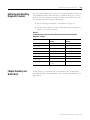
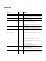
For more information on the available Receive Port and Transmit Port
communication formats, see Table 3.A.
Table 3.A
SynchLink Module Communications Formats
Receive Port Communications Format
Transfer Rate (across the fiber optic
cable) for Each Data Type:
1 Axis, 3 Direct Words, 14 Buffered
Axis Data - Updated every 500µS
Direct Data - Updated every 50µS
Buffered Data - Updated every 500µS
2 Axis
Axis Data - Updated every 250µS
2 Axis, 3 Direct Words
Axis Data - Updated every 500µS
Direct Data - Updated every 50µS
2 Direct Words, 18 Buffered
Direct Data - Updated every 50µS
Buffered Data - Updated every 250µS
4 Direct Words, 18 Buffered
Direct Data - Updated every 50µS
Buffered Data - Updated every 500µS
4 Direct Words, 8 Buffered
Direct Data - Updated every 50µS
Buffered Data - Updated every 250µS
No Receive Data
No data updated in this format
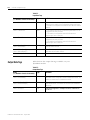
Table 3.B
SynchLink Module Communications Formats
Publication 1756-UM521A-EN-P - August 2001
Transmit Port Communications Format
Transfer Rate (across the fiber optic
cable) for Each Data Type:
1 Axis, 3 Direct Words, 14 Buffered
Axis Data - Updated every 500µS
Direct Data - Updated every 50µS
Buffered Data - Updated every 500µS
2 Axis
Axis Data - Updated every 250µS
2 Axis, 3 Direct Words
Axis Data - Updated every 500µS
Direct Data - Updated every 50µS
2 Direct Words, 18 Buffered
Direct Data - Updated every 50µS
Buffered Data - Updated every 250µS
4 Direct Words, 18 Buffered
Direct Data - Updated every 50µS
Buffered Data - Updated every 500µS
4 Direct Words, 8 Buffered
Direct Data - Updated every 50µS
Buffered Data - Updated every 250µS
Listen Only, No Transmit Data
No data updated in this format
No Transmit Data
No data updated in this format
SynchLink Module Features
3-9
Electronic Keying
Instead of plastic mechanical backplane keys, electronic keying allows
the ControlLogix system to control what modules belong in the
various slots of a configured system.
During module configuration, you must choose one of the following
keying options for your SynchLink module:
• Exact Match
• Compatible Match
• Disable Keying
When the controller attempts to connect to and configure a SynchLink
module (e.g. after program download), the module compares the
following parameters before allowing the connection and
configuration to be accepted:
•
•
•
•
•
Vendor
Product Type
Catalog Number
Major Revision
Minor Revision
The comparison is made between the keying information present in
the SynchLink module and the keying information in the controller’s
program. This feature can prevent the inadvertent operation of a
control system with the wrong module in the wrong slot.
Exact Match
All of the parameters listed above must match or the inserted module
will reject a connection to the controller.
Compatible Match
The Compatible Match mode allows a SynchLink module to determine
whether it can emulate the module defined in the configuration sent
from the controller.
With ControlLogix SynchLink modules, the module can emulate older
revisions. The module will accept the configuration if the controller’s
major.minor revision is less than or equal to the physical
module’s revision.
Publication 1756-UM521A-EN-P - August 2001
3-10
SynchLink Module Features
For example, if the configuration contains a major.minor revision of
2.7, the module inserted into the slot must have minor revision of 2.7
or higher for a connection to be made.
TIP
We recommend using Compatible Match whenever
possible. Remember, though, the module will only
work to the level of the configuration.
For example, if a slot is configured for a module with
major.minor revision of 2.7 and you insert a module
with a major.minor revision of 3.1, the module works
at the 2.7 level despite having been previously
upgraded.
If possible, we suggest you make sure configuration
is updated to match the revision levels of all
SynchLink modules. Failure to do so may not
prevent the application from working but may defeat
the purpose of upgrading your modules’ revision
levels.
Disable Keying
The inserted module attempts to accept a connection to the controller
regardless of its type.
ATTENTION
!
Be extremely cautious when using the disable
keying option; if used incorrectly, this option can
lead to personal injury or death, property damage
or economic loss.
If keying is disabled, a controller makes a connection with most
modules of the same type as that used in the slot configuration.
A controller will not establish a connection if any of the following
conditions exist, even if keying is disabled:
• The slot is configured for one module type (e.g. digital input
module) and a module of another type (e.g. SynchLink module)
is inserted in the slot.
• The module inserted into the slot cannot accept some portion of
the configuration. This case should not arise if the slot is
configured for a SynchLink module and one is inserted.
Publication 1756-UM521A-EN-P - August 2001
SynchLink Module Features
3-11
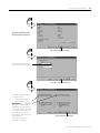
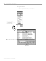
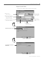
The Communications Format and Electronic Keying features are
configured on the following screen.
Communications Formats
Electronic Keying
Requested Packet Interval
The Requested Packet Interval (RPI) is a configurable parameter that
defines when the module multicasts its data onto the local chassis
backplane. In the SynchLink module, though, the RPI’s role is dictated
by the data the SynchLink transfers.
Axis Data
The RPI does not have an effect on produced or consumed axis data.
In a distributed motion control application, the coarse planner update
establishes the timing of the axis data updates from the producing
controller to the consuming 1756-SYNCH module in the master
chassis. Likewise, in the slave chassis, the RPI parameter does not
affect the delivery of the axis data to the consuming processor. This
data is produced at the coarse update rate established in the master
chassis.
Publication 1756-UM521A-EN-P - August 2001
3-12
SynchLink Module Features
Buffered, Direct and Diagnostic Data - RPI Effect on Input Data (to the
controller)
The RPI is one of two mechanisms available through the 1756-SYNCH
module to update the module’s input data onto the backplane. Input
data is transferred from the SynchLink module to its owner-controller
at the rate defined in the RPI.
In addition to the RPI, Change of State (COS) functionality also causes
the module to produce its data to the consuming controller whenever
the values of the data changes. The RPI timer is asynchronous to the
COS functionality. Both cause the module to produce data when
triggered.
Buffered, Direct and Diagnostic Data - RPI Effect on Output Data (from the
controller)
As a producing controller writes data to the 1756-SYNCH module, the
output data is placed in a local buffer until the next RPI reset occurs.
When the RPI timer expires, the output data is moved from the
controller’s local buffer to the 1756-SYNCH module.
The RPI timer is asynchronous to the program execution. Therefore, a
worst case update to the SynchLink module can be calculated by
adding the program execution time to the RPI timer setting, as
configured by the user.
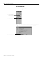
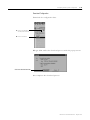
The SynchLink module minimum RPI = 2.0mS. The RPI is configured
on the following screen:
Requested Packet Interval
Publication 1756-UM521A-EN-P - August 2001
SynchLink Module Features
3-13
SynchLink Transmitted Axes
Most applications using the ControlLogix SynchLink module use it for
Remote Axis Control. You can use the SynchLink module to produce
axes from a master chassis and broadcast the data to other chassis.
The module can produce and consume two axes (i.e. Axis 0 & Axis 1).
Slave chassis consume the broadcast axis data and redistribute it to
their local motion planners (i.e. the Logix controller in their local
chassis). With this configuration, you can control multiple axes
synchronously throughout the system.
The SynchLink Transmitted Axes are configured on the following
screen:
Transmitted Axes
For an example configuration that uses Remote Axis Data, see
Appendix B, Configuring the Star Configuration.
IMPORTANT
This manual assumes you know how to set-up axis
data tags for the data the controller in the Time
Master chassis produces; this manual does not intend
to explain how to plan the motion portion of your
application as that is a controller function.
If you do not know how to set-up remote axis data
tags and account for them in the motion portion of
your application, see the ControlLogix Motion
Module Setup & Configuration User Manual,
publication 1756-6.5.16.
Publication 1756-UM521A-EN-P - August 2001
3-14
SynchLink Module Features
Transmitted Direct Words
The SynchLink module can transmit data from the following direct
word sources:
• Output Direct Words (0-3)
• Received Direct Words (0-3)
• Multiplier
In initial configuration, you can choose the Transmitted Direct Words,
but you must use ladder logic to move data to those locations in data
type tags. For more information on the data tags, see Appendix E.
Direct Words
Direct words are data delivered in a single message. A SynchLink
message can contain a maximum of four direct data words; each word
is 32 bits in length. Direct data can be automatically forwarded to the
next node in the daisy chain configuration.
Multiplier
The Multiplier multiplies one Direct Word on the receive port by the
value in the local tag "Local:x:O.Multiplier" before transmitting it out
the transmit port. This is useful when your application requires fine
adjustments to the direct word between SynchLink nodes.
EXAMPLE
If the Direct Word 0 passes process status on and the
local controller in the downstream chassis identifies
a change in the process, you can use the multiplier
to change the value of the direct word before
passing it on to the next processor.
Although you can configure the multiplier for any of the Direct Words,
it can only be used with one Direct Word at a time.
The multiplier can only transmit the same word it received (i.e. this
feature does not allow your module to receive direct word 0 and
transmit it as direct word 1). The multiplier is limited to 16 bits; any
value used in the multipler larger than 65535 is truncated to 16 bits,
and a multiplier overflow error (described below) is reported by the
Synchlink module. Make sure any data that is passed onto the Output
word is less than 65535 else you receive incorrect output data.
Publication 1756-UM521A-EN-P - August 2001
SynchLink Module Features
3-15
Mutiplier Overflow
The Multiplier Overflow bit is a data tag (Local.x.I.SynchLinkMultiplier
Overflow) that exceeds the maximum multiplier value of 65535. This value is
reported back to you through the input data tags.
IMPORTANT
If you want to pass a Multiplier Overflow value
(received from an upstream node) to a third node
downstream but not multiple the direct word data
transmitted to the downstream node, you must use a
Multiplier value = 1.
The Transmitted Direct Words are configured on the following screen:
Transmitted Direct Words
Publication 1756-UM521A-EN-P - August 2001
3-16
SynchLink Module Features
CST and SynchLink Mastership
The SynchLink module can be configured for multiple mastership and
slave roles in respect to the Coordinated System Time and the
SynchLink. For more information on these roles, see Chapter 2, Time
Synchronization in the ControlLogix System.
Time mastership is configured on the following screen.
Chapter Summary and
What’s Next
Publication 1756-UM521A-EN-P - August 2001
In this chapter, you learned about the ControlLogix SynchLink module
features. For information about Installing the SynchLink Module, see
Chapter 4.
Chapter
4
Installing the SynchLink Module
This chapter describes how to install the ControlLogix
SynchLink module.
For information on:
Noting the Power
Requirements
See page:
Noting the Power Requirements
4-1
Installing the Module
4-2
Connecting the Fiber Optic Cable
4-3
Removing the Module
4-4
Chapter Summary and What’s Next
4-5
This module receives power from the 1756 chassis power supply and
requires 2 sources of power from the backplane:
• 1200mA at 5.1V dc
• 3mA at 24V dc
Add this current/power value (6.19W) to the requirements of all other
modules in the chassis to prevent overloading the power supply.
1
Publication 1756-UM521A-EN-P - August 2001
4-2
Installing the SynchLink Module
Installing the Module
You can install or remove the module while chassis power is applied.
WARNING
!
When you insert or remove the module while
backplane power is on, an electrical arc can occur.
This could cause an explosion in hazardous location
installations. Be sure that power is removed or the
area is nonhazardous before proceeding.
Repeated electrical arcing causes excessive wear to contacts on both
the module and its mating connector. Worn contacts may create
electrical resistance that can affect module operation.
1. Align the circuit board with the top and bottom chassis guides.
Printed
Circuit
Board
20806-M
2. Slide the module into the chassis until the module locking
tabs ‘click’.
Locking tab
20807-M
Publication 1756-UM521A-EN-P - August 2001
Installing the SynchLink Module
Connecting the Fiber
Optic Cable
4-3
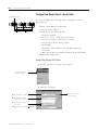
Your 1756-SYNCH module has two ports for fiber optic cables. The
front port is used to receive data, and the rear port is used to transmit
data.
1. Remove the plugs from the ports at the bottom of the module.
TIP
Keep the plugs that were removed to connect the
fiber optic cables. When the cables are disconnected,
you can reinsert the plugs into the ports to protect
them.
2. Connect the fiber optic cables as shown below.
Figure 4.1
LINK
COMM
LINK
SYNC
OK
Tx (rear)
Rx(front)
31267
ATTENTION
!
Do not look directly into the fiber ports or fiber
cables. Light levels may cause damage to eyesight.
The SynchLink module is a Class 1 LED product.
Publication 1756-UM521A-EN-P - August 2001
4-4
Installing the SynchLink Module
Table 4.A lists the possible connections that might be made to your
1756-SYNCH module and where to connect the fiber optic cable.
Table 4.A
Making Fiber Optic Cable Connections to the 1756-SYNCH Module
If your 1756-SYNCH
Make this fiber optic cable connection:
module is configured to:
transmit data only
Connect the fiber optic cable to the rear port. The other end
of the cable should be connected to a device receiving data
over the SynchLink from your 1756-SYNCH module.
receive data only
Connect the fiber optic cable to the front port. The other end
of the cable should be connected to a device transmitting
data to your 1756-SYNCH module over the SynchLink.
transmit and receive data
1. Connect the fiber optic cable going to (i.e. transmitting
the data to) a module receiving the data to the front port.
2. Connect the fiber optic cable coming from (i.e. receiving
the data from) a module transmitting data to the rear port.
This completes installation. Use the next section to remove your
SynchLink module if necessary.
Removing the Module
ATTENTION
Before you remove the module, you must disconnect
the fiber optic cables.
!
1. Pull the fiber optic cable out of the connection port.
TIP
Publication 1756-UM521A-EN-P - August 2001
If you kept the plugs that were removed to
connect the fiber optic cables, reinsert them to
protect the ports.
Installing the SynchLink Module
4-5
2. Push in the top and bottom locking tabs.
3. Pull the module out of the chassis as shown.
Figure 4.2
Locking tabs
20808-M
Chapter Summary and
What’s Next
In this chapter, you learned how to install the ControlLogix SynchLink
module. For information about Configuring the SynchLink Module,
see Chapter 5.
Publication 1756-UM521A-EN-P - August 2001
4-6
Installing the SynchLink Module
Notes:
Publication 1756-UM521A-EN-P - August 2001
Chapter
5
Configuring the SynchLink Module
This chapter describes how to configure the ControlLogix SynchLink
module using RSLogix 5000 programming software.
For information on:
See page:
Overview of the Configuration Process
5-2
Choose a SynchLink Configuration
5-3
Chapter Summary and What’s Next
5-10
You must configure your module upon installation. The module will
not work until it has been configured.
This chapter offers a configuration overview and the three available
ControlLogix SynchLink configurations. For specific examples of each
configuration, see the following:
• Star Configuration - Appendix B - This example shows a
configuration using Remote Axis Data.
• Daisy Chain Configuration - Appendix C
• Ring Configuration - Appendix D
RSLogix 5000 Configuration Software
Use RSLogix 5000 to write configuration for your SynchLink module.
You must write configuration for each module because module
position in the SynchLink system affects configuration. For example, if
a SynchLink module is the Time Master for the system, it must be
configured as such.
1
Publication 1756-UM521A-EN-P - August 2001
5-2
Configuring the SynchLink Module
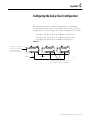
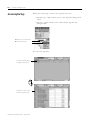
Overview of the
Configuration Process
Figure 5.1 shows an overview of the configuration process:
Figure 5.1
1. Choose a SynchLink configuration.
Star Configuration
Daisy Chain Configuration
Ring Configuration
2. Create a new
RSLogix 5000
project.
Steps 2 - 5 must be
taken for every
SynchLink module
(and its respective
chassis) in the
chosen SynchLink
configuration.
These configuration
changes occur
before module
operation begins.
3. Add a
SynchLink
module to
the RSLogix
5000 project.
4. Use the
wizard to
configure the
SynchLink
module.
5. Go online to download new
configuration to the module.
Steps 6 - 7 should
only be taken as
necessary for each
module.
These configuration
changes occur after
module operation
has begun.
Publication 1756-UM521A-EN-P - August 2001
6. Change configuration (via
RSLogix 5000) as necessary.
7. Send new configuration (via
RSLogix 5000) to the module.
42986
Configuring the SynchLink Module
Choose a SynchLink
Configuration
5-3
You must use one of the following SynchLink configurations:
Star Configuration - See Appendix B for an example.
ControlNet
SynchLink
Hub
Hub
Hub
42747
Daisy Chain Configuration - See Appendix C for an example.
SynchLink
ControlNet
42746
Ring Configuration - See Appendix D for an example.
SynchLink
ControlNet
42748
Publication 1756-UM521A-EN-P - August 2001
5-4
Configuring the SynchLink Module
Create a New RSLogix 5000 Project
1. Use the File menu to create a new project.
Choose a New project
from the File menu.
2. Name the controller.
A. This controller is a 1756-L1.
B. This controller is named
Time_Master_chassis.
C. This controller is used in a
7-slot chassis.
D. The controller slot number
is 0.
Publication 1756-UM521A-EN-P - August 2001
E. Click here to use the
new controller.
Configuring the SynchLink Module
5-5
Add a SynchLink Module
1. Select a SynchLink module as shown below.
A. Select I/O Configuration.
B. Click on the right mouse button
to display the menu.
C. Select New Module
Make sure the
Major Revision
number matches
the label on the
side of your module
A. Select a 1756-SYNCH module
B. Click here
Publication 1756-UM521A-EN-P - August 2001
5-6
Configuring the SynchLink Module
Configure the SynchLink Module
1. Use the new module creation wizard as shown below.
A. Module name is
Time_Master.
D. Module slot
number is 3.
B. Receive Port Comm Format is
No Receive Data.
E. Electronic Keying
method is
Compatible Module.
C. Transmit Port Comm Format is
1 Axis, 3 Direct Words,
14 Buffered.
F. Minor Revision = 1.
G. Click here after
completing the
information on this page.
Requested Packet Interval = 20mS
Click here to move to the next page
Use the pull-down menu, to choose
which axis data tags to transmit
over each axis.
Click here to move to the next page
Publication 1756-UM521A-EN-P - August 2001
Configuring the SynchLink Module
5-7
The Module Identification page is
blank during initial configuration.
Click here to move to the next page
Use the pull-down menus to choose
which direct words are transmitted.
Click here to move to the next page
The example module is configured
as the Time Master for:
• the chassis - optional
• the SynchLink - required
IMPORTANT: In this configuration,
the SynchLink module must be the
Time Master of the SynchLink, but it
is not required to be the Time Master
of the chassis. If the module is not
the Time Master of the chassis, it
receives the CST timer value from the
chassis backplane.
For more information on Time
Mastership, see Chapter 2.
Click here to finish configuration.
Publication 1756-UM521A-EN-P - August 2001
5-8
Configuring the SynchLink Module
Download Configuration
Download the configuration data.
A. Click on the triangle to
see the pull-down menu.
B. Click on Download.
RSLogix 5000 verifies the download process with this pop-up screen.
Click here to download new data
This completes the download process.
Publication 1756-UM521A-EN-P - August 2001
Configuring the SynchLink Module
Changing Configuration
After Module Operation
Has Begun
5-9
You change configuration for your SynchLink module after operation
has begun, but you must go offline first. Follow these steps to change
the SynchLink module configuration:
1. Go offline.
A. Click on the triangle to see
the pull-down menu.
B. Click on Go Offline.
2. Access the module properties in RSLogix 5000.
A. Right-click on the module
to see the pull-down menu.
B. Click on Properties.
Publication 1756-UM521A-EN-P - August 2001
5-10
Configuring the SynchLink Module
3. Make the necessary changes.
A. In this example, the
Connection tab was
accessed to change the RPI.
B. Click on OK to
make the changes..
Chapter Summary and
What’s Next
In this chapter, you learned about the general configuration
process. For specific configuration examples, see:
• Appendix B - Star Configuration with Remote Axis Data
• Appendix C - Daisy Chain Configuration
• Appendix D - Ring Configuration
For information on Troubleshooting the SynchLink Module, see
Chapter 6.
Publication 1756-UM521A-EN-P - August 2001
Chapter
6
Troubleshooting the SynchLink Module
This chapter describes how to troubleshoot the ControlLogix
SynchLink module.
For information on:
Using the Status Indicators
See page:
Using the Status Indicators
6-1
Using RSLogix 5000 to Troubleshoot the
Module
6-3
Chapter Summary and What’s Next
6-11
The SynchLink module uses status indicators to show SynchLink and
communications status (red/green) and a bi-colored LED for module
"OK" (red/green).
SynchLink
LINK
COMM
LINK
SYNC
OK
42875
During power up, an indicator test is done and the following occurs:
• The "OK" indicator turns red for 1 second and then turns to
flashing green if it has passed the self-test.
1
Publication 1756-UM521A-EN-P - August 2001
6-2
Troubleshooting the SynchLink Module
Use Table 6.A to troubleshoot your module.
Table 6.A
Troubleshooting the 1756-SYNCH Module
LED
indicators:
This
display:
Means:
Take this action:
COMM
Steady green
light
The module is configured and
operating properly.
None
COMM
Off
1. The module is not powered.
2. The module is not configured.
3. The module is configured to
receive data from SynchLink
but did not receive it in the
last scan.
4. The module is configured to
transmit on SynchLink but
has not enabled its
transmitter.
5. The Transmit and Receive
communications formats do
not match between linked
modules.
1. Power the module.
2. Configure the module.
3. Check fiber connections and
diagnostic counter for errors.
If the problem persists,
replace the cable or module.
4. Make sure configuration is
complete and downloaded. If
the problem persists, replace
the module.
5. In RSLogix 5000, make sure
communications formats
match between linked
modules.
SYNC
Steady green
light
The module is the Time Master
or a time relay and
synchronization is complete.
None
SYNC
Flashing
green light
1. The module is configured as a 1. Establish a CST master on the
time relay from chassis
backplane.
backplane to SynchLink but is
not synchronized with a CST
master on the backplane.
2. The module is configured as a 2. Check configuration and
time relay from SynchLink to
make sure all modules in the
chassis backplane but has
system are properly
not synchronized with the
connected and online.
upstream device.
Publication 1756-UM521A-EN-P - August 2001
Troubleshooting the SynchLink Module
6-3
Table 6.A
Troubleshooting the 1756-SYNCH Module
LED
indicators:
This
display:
Means:
SYNC
Flashing red
light
1. The module is configured as 1. Check configuration
throughout the system and
the CST Time Master and has
verify there is only one CST
detected another CST Time
Time Master.
Master.
2. The configuration information 2. Check configuration of this
module and all upstream
received from SynchLink does
SynchLink devices.
not match the module’s
configuration.
3. The module is configured as 3. Check configuration for all
modules in the system to
Time Master on SynchLink
make sure only one is the
and has received time
SynchLink Time Master.
information from another
Time Master on SynchLink.
SYNC
Off
1. The module is not powered. 1. Power the module.
2. The module is not configured 2. Configure the module for its
as Time Master or time relay.
proper function.
OK
Steady green
light
The module is operating
properly.
None
OK
Flashing
green light
The module is powered and
ready for operation but has not
received configuration.
Configure the module.
OK
Steady red
light
The module has experienced an
unrecoverable error.
Replace the module.
OK
Flashing red
light
A flash upgrade is in process.
Wait for upgrade to finish. New
application code may be needed
afterward.
OK
Off
The module is not powered.
Power the module, if needed.
Using RSLogix 5000 to
Troubleshoot the Module
Take this action:
In addition to the LED display on the module, RSLogix 5000 alerts you
to fault conditions. You are alerted in the following ways:
• Warning signal on the main screen next to the module-This
occurs when the connection to the module is broken
• Notification in the Tag Editor - General module faults are also
reported in the Tag Editor.
• Status on the Module Info Page
Publication 1756-UM521A-EN-P - August 2001
6-4
Troubleshooting the SynchLink Module
The screens below display fault notification in RSLogix 5000.
Warning signal on main screen
!
Warning icon when a
communications fault occurs
or if the module is inhibited
!
Warning signal - The module in slot 1 has a communications fault
Fault message in status line
Status section lists Major and
Minor Faults and the Internal
State of the module
Allen-Bradley
None
Specialty I/O
1756-SYNCH
None
Unconnected
1.1
FFFFFFFF
Yes
No
Match
1756-SYNCH Ver. 1.0
Ok
Yes
Status line provides information on
the connection to the module
Faulted
Notification in Tag Editor
A value of 1 shows a fault for this
input point.
IMPORTANT: If all input fault bits are
set to 1, the controller cannot connect
to the module. In this case, the use the
Connection tab in the RSLogix 5000
properties wizard (see page 6-5) to
determine the problem. Also, the
RSLogix 5000 online help offers a
definition of all fault bits.
Publication 1756-UM521A-EN-P - August 2001
Refresh
Reset Module
Troubleshooting the SynchLink Module
6-5
Determining Fault Type
When you are monitoring a module’s configuration properties in
RSLogix 5000 and receive a Communications fault message, the
Connection page lists the type of fault.
The fault type is listed here
In this example, Error 16#0011
means Counter 0 was set to an
invalid Operational Mode
For a detailed listing of the possible faults, their causes and suggested
solutions, see Module Table Faults in the online help.
Publication 1756-UM521A-EN-P - August 2001
6-6
Troubleshooting the SynchLink Module
Using Diagnostic Counters
The 1756-SYNCH module uses diagnostic counters; the counters
contain additional information about the module. See Table 6.B for
more information on the SynchLink module diagnostic counters. This
information must be used in the Destination field of the Configuration
pop-up screen (page 6-9).
For more information on how to access the diagnostic counter
information, see page 6-7.
Table 6.B
SynchLink Module Diagnostic Counters
Name:
Description:
Data Type
Attribute ID:
Possible Values:
Status
Status of this device on the
SynchLink system
DINT
1
This counter lists the status of the following bits (0 = bit is
not faulted, 1 = bit is faulted):
• Bit 0 - Reserved (default =0)
• Bit 1 - Reserved (default =0)
• Bit 2 - Receive fault. No data has been received from
the upstream device.
• Bit 3 - Data Fault. The upstream device is in the idle
state.
• Bit 4 - Data Comm Format Mismatch Fault. The
communications format of data received from the
upstream device does not match this device’s receive
port communications format.
• Bit 5 – Duplicate SynchLink Time Master Fault – This
device is configured to be SynchLink Time Master but
has received a CST update from another Time Master
• Bit 6 – CST Drifting – CST synchronization with
SynchLink was not verified at last beacon but was
verified within last 6 beacon updates
• Bit 7 – CST Synchronization Fault – The device CST is
not synchronized with SynchLink.
• Bit 8 – Multiplier Overflow Fault – The output of the
multiplier exceeded 16 bits
• Bit 9 – Axis 0 Receive Fault – The device is
configured to receive Axis 0, but Axis 0 was not
received from the SynchLink system.
• Bit 10 – Axis 1 Receive Fault – The device is
configured to receive Axis 1, but Axis 1 was not
received from the SynchLink system.
• Bit 11 – Axis 0 Unclaimed Fault – Axis 0 was
received from the SynchLink system but was not
consumed by the local controller.
• Bit 12 - Axis 1 Unclaimed Fault – Axis 1 was received
from the SynchLink system but was not consumed by
the local controller.
• Bit 13 – Axis 0 Transmit Fault – The device is
configured to transmit Axis 0, but Axis 0 was not
produced by the local controller.
• Bit 14 – Axis 1 Transmit Fault – The device is
configured to transmit Axis 1, but Axis 1 was not
produced by the local controller.
• Bit 15 – SynchLink Revision Fault – The SynchLink
revision was received but the data
is not compatible with the receiving module’s
revision.
• Bits 16 to 31 – Unused (Default = 0)
CRC Error
Counter
Number of CRC errors detected
on the SynchLink system since
power-up or last reset service
DINT
2
0 to 232 - 1
Publication 1756-UM521A-EN-P - August 2001
Troubleshooting the SynchLink Module
6-7
Table 6.B
SynchLink Module Diagnostic Counters
Name:
Description:
Data Type
Attribute ID:
Possible Values:
Framing Error
Counter
Number of framing errors
detected on SynchLink since
powerup or last reset service
DINT
3
0 to 232 - 1
Incomplete
Package Error
Counter
Number of incomplete package
errors detected on SynchLink
since powerup or last reset
service
DINT
4
0 to 232 - 1
SynchLink
Revision
Revision of SynchLink supported DINT
5
Bits 0 to 15 - Minor Revision
Bits 16 to 31 - Major Revision
Message Instructions
To retrieve and reset the SynchLink diagnostic counter information,
you must use a message instruction in ladder logic and a CIP message.
This ladder logic is written in the Main Routine section of
RSLogix 5000.
Double-click here to
enter the Main Routine
After adding a message
instruction to a rung, you
must create a tag for the
message instruction
1 Right-click on the
question mark (?) to see
this pull-down menu.
2 Click here to Create a
New Tag.
Publication 1756-UM521A-EN-P - August 2001
6-8
Troubleshooting the SynchLink Module
Fill in the following information when the New Tag pop-up
screen appears:
IMPORTANT
We suggest you name the tag to indicate what
module service the message instruction is sending.
For example, the message instruction below is used
to retrieve diagnostic counters, and the tag is named
to reflect this.
Name the tag here.
Enter an optional description here.
Choose the Base Tag Type here.
Choose the Message Data Type here.
Choose the Controller Scope here.
IMPORTANT: Message tags can only
be created with the Controller Scope.
Message Configuration
After creating a new tag, you must enter message configuration.
Click here to see the message
configuration pop-up screens
Publication 1756-UM521A-EN-P - August 2001
Troubleshooting the SynchLink Module
6-9
Enter message configuration on the following screens:
• Configuration Pop-Up Screen
• Communication Pop-Up Screen
A description of the purpose and set-up of each screen follows.
Configuration Pop-Up Screen
This pop-up screen provides information on what module service to
perform and where to perform it. For example, you must use this
screen to retrieve diagnostic counters (module service) from the
1756-SYNCH module (where to perform service).
Message Type is CIP Generic
Service Code is 1
Class Name is 31B
Instance Name is 1
Attribute name is 0
There is no Source.
Number of Elements is 0
Destination is a tag of
type DINT [5].
IMPORTANT: The
data containted in
this DINT is described
in Table 6.B.
Publication 1756-UM521A-EN-P - August 2001
6-10
Troubleshooting the SynchLink Module
Communication Pop-Up Screen
This pop-up screen provides information on the path of the message
instruction. For example, the slot number of a 1756-SYNCH module
distinguishes exactly which module a message is designated for.
IMPORTANT
Use the Browse button to see a list of the I/O
modules in the system. You choose a path when you
choose a module from the list.
You must name an I/O module during initial module
configuration to choose a path for your message
instruction.
Use this Browse
button to see a
list such as the
one displayed
below.
1. Choose the module
that is to receive
the message
instruction.
4. Click on OK.
Publication 1756-UM521A-EN-P - August 2001
Troubleshooting the SynchLink Module
Retrieving and Resetting
Diagnostic Counters
6-11
You can use the diagnostic counters to recognize a problem with your
1756-SYNCH module. After correcting a problem, though, you may
want to reset the counters for future use. The counters are also reset
via message instructions and a CIP message.
1. Create a message instruction, as described on page 6-7.
2. Use the values listed in on the Configuration Pop-Up Screen to
retrieve or reset the counters.
Table 6.C
Configuration Pop-Up Screen Values Required to Reset SynchLink Module
Diagnostic Counters
Chapter Summary and
What’s Next
Field:
Value to Retrieve the
Counter:
Value to Reset the
Counter:
Message Type
CIP Generic
CIP Generic
Service Code
5
5
Class
31B
31B
Instance
1
1
Attribute
0
0
Source
NA
NA
Source Length
0
0
Destination
Retrieve Diagnostic
Counters
NA
In this chapter, you learned how to troubleshoot the ControlLogix
SynchLink module. For information on the module specifications, see
Appendix A.
Publication 1756-UM521A-EN-P - August 2001
6-12
Troubleshooting the SynchLink Module
Notes:
Publication 1756-UM521A-EN-P - August 2001
Appendix
A
Specifications
General Specifications
Module Location
1756 ControlLogix chassis
Backplane Current
1200mA @ 5.1V dc & 3mA @ 24V dc
Maximum Power Dissipation
6.19W
Thermal Dissipation
21.1 BTU/hr
Connecting Cable
Fiber Type
Fiber Termination Type
Assemblies
Maximum Length
Minimum Length
200/230 micron Hard Clad Silica (HCS),
Versalink V-System
Order assemblies from Rockwell Automation under
catalog 1403-CFxxx (xxx=length in meters) or from
Lucent Technologies Specialty Fiber Technologies
Division
300m
1m
Operating Wavelength
650nm (red)
SynchLink Data Rate
5Mbps
Baud Rate
5Mbaud
Type of Communication
Synchronous
Frame Parameters
3 Flags - 3 bytes
Control field - 1 byte
Data field - 24 bytes
CRC field - 2 bytes
Frame Period
50µs
Indicators
Green and red indicators for operation,
status and diagnostics
Environmental Conditions
Operating Temperature
Storage Temperature
Relative Humidity
Shock Operating
Non-operating
Vibration
0 to 60°C (32 to 140°F)
-40 to 85°C (-40 to 185°F)
5 to 95% noncondensing
30g peak acceleration, 11(+ 1ms) pulse width
50g peak acceleration, 11(+ 1ms) pulse width
Tested 2g @ 10-500Hz per IEC 68-2-6
Agency Certification
(when product or
packaging is marked)
Listed Industrial Control Equipment
Certified Process Control Equipment
Certified Class I, Division 2, Group A, B, C, D
Marked for all applicable directives
Marked for all applicable acts
N223
1
Publication 1756-UM521A-EN-P - August 2001
A-2
Specifications
Notes:
Publication 1756-UM521A-EN-P - August 2001
Appendix
B
Configuring the Star Configuration
This appendix describes how to configure the ControlLogix SynchLink
module in a Star configuration using remote axis control. In this
example configuration, the following occurs:
• The controller in the Time Master chassis produces axis data.
• The axis data is transmitted via SynchLink modules to each Time
Slave chassis.
• The controller in each Time Slave chassis consumes the axis
data.
The system’s physical configuration is shown in Figure B.1. In this
configuration, you must:
• configure the Master Node in an RSLogix 5000 project.
• configure each End Node in separate RSLogix 5000 projects.
Figure B.1
The SynchLink module in
this chassis is configured
as the Time Master for
the SynchLink.
Master Node
ControlNet
SynchLink
Hub
End Node
End Node
42882
The SynchLink modules in these chassis are configured as
the CST Time Masters and SynchLink Time Slaves.
1
Publication 1756-UM521A-EN-P - August 2001
B-2
Configuring the Star Configuration
Using Remote Axis Control
Most applications using the ControlLogix SynchLink module use it for
Remote Axis Control. You can use the SynchLink module to produce
axes from a master chassis and broadcast the data to other chassis.
Slave chassis consume the broadcast axis data and redistribute it to
their local motion planners (i.e. the Logix controller in their local
chassis). With this configuration, you can control multiple axes
synchronously throughout the system.
IMPORTANT
This example assumes you have already set-up axis
data tags for the data the controller in the Time
Master chassis produces; this manual does not intend
to explain how to plan the motion portion of your
application as that is a controller function.
If you do not know how to set-up remote axis data
tags and account for them in the motion portion of
your application, see the ControlLogix Motion
Module Setup & Configuration User Manual,
publication 1756-6.5.16.
Time Master Chassis
ControlNet
SynchLink
Hub
Publication 1756-UM521A-EN-P - August 2001
Configure Time Master Chassis - Master Node
You must complete the following tasks to configure the time
master chassis.
• Create a New RSLogix 5000 Project
• Add a SynchLink Module
• Configure the SynchLink Module
– Name the module
– Choose a receive communications format
– Choose a transmit communications format
– Choose an electronic keying option
– Set the RPI
– Determine if the module is the CST Time Master for
the chassis
– Make the module the Time Master for the SynchLink
• Download Configuration
Configuring the Star Configuration
B-3
Create a New RSLogix 5000 Project
1. Use the File menu to create a new project.
Choose a New project
from the File menu.
2. Name the controller.
A. This controller is a 1756-L1.
E. Click here to use the
new controller.
B. This controller is named
Time_Master_chassis.
C. This controller is used in a
7-slot chassis.
D. The controller slot number
is 0.
Publication 1756-UM521A-EN-P - August 2001
B-4
Configuring the Star Configuration
Add a SynchLink Module
1. Select a SynchLink module as shown below.
A. Select I/O Configuration.
B. Click on the right mouse button
to display the menu.
C. Select New Module
Make sure the
Major Revision
number matches
the label on the
side of your module
A. Select a 1756-SYNCH module
B. Click here
Publication 1756-UM521A-EN-P - August 2001
Configuring the Star Configuration
B-5
Configure the SynchLink Module
1. Use the new module creation wizard as shown below.
A. Module name is
Time_Master.
D. Module slot number
is 3 as shown in the
graphic on page B-1.
B. Receive Port Comm Format is
No Receive Data because the
module is the master of a Star
and does not receive data.
C. Transmit Port Comm Format is
2 Axis.
E. Electronic Keying
method is Compatible
Module.
F. Minor Revision = 1.
G. Click here after
completing the
information on this page.
Requested Packet Interval = 20mS
Click here to move to the next page
Use the pull-down menu, to choose
which axis data tags to transmit over
each axis. This menu lists the Axis
tags currently defined in the project.
Use this button to define a new
Axis tag.
IMPORTANT: All produced tags
must be checked as produced tags in
the Tag Editor. For more information
on accessing data tags, see
Appendix E.
Click here to move to the next page
Publication 1756-UM521A-EN-P - August 2001
B-6
Configuring the Star Configuration
The Module Identification page is
blank during initial configuration.
Click here to move to the next page
The module does not transmit any
direct words because the
Communications Format only calls
for Axis data.
Click here to move to the next page
The module is configured as the Time
Master for:
• the chassis - optional
• the SynchLink - required
IMPORTANT: In this configuration,
the SynchLink module must be the
Time Master of the SynchLink, but it
is not required to be the Time Master
of the chassis. If the module is not
the Time Master of the chassis, it
receives the CST timer value from the
chassis backplane.
Publication 1756-UM521A-EN-P - August 2001
Click here to finish configuration.
Configuring the Star Configuration
B-7
Download Configuration
Download the configuration data.
A. Click on the triangle to
see the pull-down menu.
B. Click on Download.
RSLogix 5000 verifies the download process with this pop-up screen.
Click here to download new data
This completes the download process.
Publication 1756-UM521A-EN-P - August 2001
B-8
Configuring the Star Configuration
Configure Time Slave Chassis - End Node
CST Time
Slave Chassis
ControlNet
Hub
SynchLink
You must complete the following tasks to configure the first time
slave chassis.
• Create a New RSLogix 5000 Project
• Add a SynchLink Module
• Configure the SynchLink Module
– Name the module
– Choose a receive communications format
– Choose a transmit communications format
– Choose an electronic keying option
– Set the RPI
– Set the module as the CST Time Master for the chassis
• Create Axis Data Tags
• Download Configuration
Create a New RSLogix 5000 Project
1. Use the File menu to create a new project.
Choose a New project
from the File menu.
2. Name the controller.
A. The controller is a 1756-L1.
B. The controller is named
Time_Slave_End_Node_1.
C. The controller is used in a
7-slot chassis.
D. The controller’s slot location
is 0.
Publication 1756-UM521A-EN-P - August 2001
F. Click here to use the
new controller.
Configuring the Star Configuration
B-9
Add a SynchLink Module
1. Select a SynchLink module as shown below.
A. Select I/O Configuration.
B. Click on the right mouse button
to display the menu.
C. Select New Module
Make sure the
Major Revision
number matches
the label on the
side of your module
A. Select a 1756-SYNCH module
B. Click here
Publication 1756-UM521A-EN-P - August 2001
B-10
Configuring the Star Configuration
Configure the SynchLink Module
1. Use the new module creation wizard as shown below.
A. Module name is
SynchLink_Module_Slave.
D. Module slot number
is 3 as shown in the
graphic on page B-1.
B. Receive Port Comm Format is
2 Axis to match the Transmit
Port Comm Format of the
master module.
C. Transmit Port Comm Format is
No Transmit Data.
E. Electronic Keying
method is Compatible
Module.
F. Minor Revision = 1.
G. Click here after
completing the
information on this page.
Requested Packet Interval = 20mS
Click here to continue to the next screen.
Time Slave modules must be
configured as Time Masters for their
respective chassis if you want to
synchronize each chassis’ CST time
value with the CST Time Master.
This module must also NOT be
configured as the CST master of
the SynchLink (i.e. the box is
unchecked)
Click here to finish configuration. This module does not transmit SynchLink
axis or direct words so the screens shown on pages B-5 & B-6 are not used.
Publication 1756-UM521A-EN-P - August 2001
Configuring the Star Configuration
B-11
Create Axis Data Tags
You must create axis data tags for the controller in this chassis to
consume. The axis data is originally produced in the Time Master
chassis and broadcast to SynchLink modules in other chassis over the
fiber optic cable. SynchLink modules in each Time Slave chassis then
consume the data from the cable and produce it in the local chassis.
The owner controller in their local chassis consumes the data from the
local SynchLink module.
Follow these steps to create axis data tags in the consuming chassis:
1. Create a New Tag for Axis 0.
A. Select Controller Tags.
B. Right-click to display
the menu.
C. Select New Tag.
F. Click on OK to create the new tag.
A. Name the new tag.
B. Change the Tag Type
to Consumed.
C. Use the pull-down menu
to change the Producer to
the SynchLink module in
the local chassis.
D. Type in the Remote Tag
Name. This name must
either be Axis0 or Axis1.
IMPORTANT: If you use any
Remote Tag Name other
than Axis0 or Axis1, the
remote axis data will NOT
be consumed.
E. Change the Data Type to Axis.
Publication 1756-UM521A-EN-P - August 2001
B-12
Configuring the Star Configuration
2. Create a new tag for Axis 1. The tag should look like the
example below.
F. Click on OK to create the new tag.
A. Name the new tag.
B. Change the Tag Type
to Consumed.
C. Use the pull-down menu
to change the Producer to
the SynchLink module in
the local chassis.
D. Type in the Remote Tag
Name. This name must
either be Axis0 or Axis1.
IMPORTANT: If you use any
other Remote Tag Name
(other than Axis0 or Axis1)
the remote axis data will
NOT be consumed.
E. Change the Data Type to Axis.
Download Configuration
Download the configuration data.
A. Click on the triangle to
see the pull-down menu.
B. Click on Download.
RSLogix 5000 verifies the download process with this pop-up screen.
Click here to download new data
This completes the download process.
Publication 1756-UM521A-EN-P - August 2001
Configuring the Star Configuration
B-13
Configure Time Slave Chassis - End Node
Hub
SynchLink
Time Slave
Chassis
ControlNet
You must complete the following tasks to configure the second CST
Time Slave chassis. This set of tasks is exactly the same as those
described on page B-8 for the first End Node but are repeated here.
• Create a New RSLogix 5000 Project
• Add a SynchLink Module
• Configure the SynchLink Module
– Name the module
– Choose a receive communications format
– Choose a transmit communications format
– Choose an electronic keying option
– Set the RPI
– Set the module as the CST Time Master for the chassis
• Create Axis Data Tags
• Download Configuration
Create a New RSLogix 5000 Project
1. Use the File menu to create a new project.
Choose a New project
from the File menu.
2. Name the controller.
A. The controller is a 1756-L1.
F. Click here to use the
new controller.
B. The controller is named
Time_Slave_End_Node_2.
C. The controller is used in a
7-slot chassis.
D. The controller’s slot location
is 0.
Publication 1756-UM521A-EN-P - August 2001
B-14
Configuring the Star Configuration
Add a SynchLink Module
1. Select a SynchLink module as shown below.
A. Select I/O Configuration.
B. Click on the right mouse button
to display the menu.
C. Select New Module
Make sure the
Major Revision
number matches
the label on the
side of your module
A. Select a 1756-SYNCH module
B. Click here
Publication 1756-UM521A-EN-P - August 2001
Configuring the Star Configuration
B-15
Configure the SynchLink Module
1. Use the new module creation wizard as shown below.
A. Module name is
Time_Slave_End_Node_1.
D. Module slot number
is 3 as shown in the
graphic on page B-1.
B. Receive Port Comm Format is
2 Axis.
C. Transmit Port Comm Format is
No Transmit Data.
E. Electronic Keying
method is Compatible
Module.
F. Minor Revision = 1.
G. Click here after
completing the
information on this page.
Requested Packet Interval = 20mS
Click here to continue to the next screen.
Time slave modules must be
configured as Time Masters for
their respective chassis if you
want to synchronize each
chassis’ CST time value with the
CST Time Master.
Click here to finish configuration. This module does not transmit SynchLink
axis or direct words so the screens shown on pages B-5 & B-6 are not used.
Publication 1756-UM521A-EN-P - August 2001
B-16
Configuring the Star Configuration
Create Axis Data Tags
You must create axis data tags for the controller in this chassis to
consume. The axis data is originally produced in the Time Master
chassis and broadcast to SynchLink modules in other chassis over the
fiber optic cable. SynchLink modules in each Time Slave chassis then
consume the data from the cable and produce it in the local chassis.
The owner controller in their local chassis consumes the data from the
local SynchLink module.
Follow these steps to create axis data tags in the consuming chassis:
1. Create a New Tag for Axis 1.
A. Select Controller Tags.
B. Right-click to display
the menu.
C. Select New Tag.
F. Click on OK to create the new tag.
A. Name the new tag.
B. Change the Tag Type
to Consumed.
C. Use the pull-down menu
to change the Producer to
the SynchLink module in
the local chassis.
D. Type in the Remote Tag
Name. This name must
either be Axis0 or Axis1.
IMPORTANT: If you use any
other Remote Tag Name
(other than Axis0 or Axis1)
the remote axis data will
NOT be consumed.
Publication 1756-UM521A-EN-P - August 2001
E. Change the Data Type to Axis.
Configuring the Star Configuration
B-17
2. Create a new tag for Axis 1. The tag should look like the
example below.
F. Click on OK to create the new tag.
A. Name the new tag.
B. Change the Tag Type
to Consumed.
C. Use the pull-down menu
to change the Producer to
the SynchLink module in
the local chassis.
D. Type in the Remote Tag
Name. This name must
either be Axis0 or Axis1.
IMPORTANT: If you use any
other Remote Tag Name
(other than Axis0 or Axis1)
the remote axis data will
NOT be consumed.
E. Change the Data Type to Axis.
Download Configuration
Download the configuration data.
A. Click on the triangle to
see the pull-down menu.
B. Click on Download.
Publication 1756-UM521A-EN-P - August 2001
B-18
Configuring the Star Configuration
RSLogix 5000 verifies the download process with this pop-up screen.
Click here to download new data
This completes the download process.
When all the chassis in the Star Configuration are configured and
operating online (i.e. configuration was downloaded) the chassis
synchronize with the CST Time Master.
Publication 1756-UM521A-EN-P - August 2001
Appendix
C
Configuring the Daisy Chain Configuration
This appendix provides a sample configuration for a SynchLink
system using the Daisy Chain Configuration. The system’s physical
configuration is shown in Figure C.1. In this configuration, you must:
• configure the Master Node in an RSLogix 5000 project.
• configure the Center Node in an RSLogix 5000 project.
• configure the End Node in an RSLogix 5000 project.
Figure C.1
The SynchLink module in
this chassis is configured
as the Time Master for
the for the SynchLink.
Master Node
SynchLink
Center Node
End Node
ControlNet
42883
The SynchLink modules in these chassis
are configured as the CST Time Masters.
1
Publication 1756-UM521A-EN-P - August 2001
C-2
Configuring the Daisy Chain Configuration
Configure Time Master Chassis - Master Node
Time Master Chassis
You must complete the following tasks to configure the time
master chassis.
ControlNet
SynchLink
• Create a New RSLogix 5000 Project
• Add a SynchLink Module
• Configure the SynchLink Module
– Name the module
– Choose a receive communications format
– Choose a transmit communications format
– Choose an electronic keying option
– Set the RPI
– Determine if the module is the CST Time Master for
the chassis
– Make the module the Time Master for the SynchLink
• Download Configuration
Create a New RSLogix 5000 Project
1. Use the File menu to create a new project.
Choose a New project
from the File menu.
2. Name the controller.
A. The controller is a 1756-L1.
B. The controller is named
Time_Master_chassis.
C. The controller is used in a
7-slot chassis.
D. The controller slot number
is 0.
Publication 1756-UM521A-EN-P - August 2001
E. Click here to use the
new controller.
Configuring the Daisy Chain Configuration
C-3
Add a SynchLink Module
1. Select a SynchLink module as shown below.
A. Select I/O Configuration.
B. Click on the right mouse button
to display the menu.
C. Select New Module
Make sure the
Major Revision
number matches
the label on the
side of your module
A. Select a 1756-SYNCH module
B. Click here
Publication 1756-UM521A-EN-P - August 2001
C-4
Configuring the Daisy Chain Configuration
Configure the SynchLink Module
1. Use the new module creation wizard as shown below.
A. Module name is
Time_Master.
D. Module slot number
is 3 as shown in the
graphic on page C-1.
B. Receive Port Comm Format is
No Receive Data.
E. Electronic Keying
method is Compatible
Module.
C. Transmit Port Comm Format is
2 Direct Words, 18 Buffered.
F. Minor Revision = 1.
G. Click here after
completing the
information on this page.
Requested Packet Interval = 20mS
Click here to move to the next page
This module does not transmit any
SynchLink axes.
Click here to move to the next page
Publication 1756-UM521A-EN-P - August 2001
Configuring the Daisy Chain Configuration
C-5
The Module Identification page is
blank during initial configuration.
Click here to move to the next page
The module transmits 2 Direct
Words, as specified in the transmit
port communications format.
Click here to move to the next page
The module is configured as the Time
Master for:
• the chassis - optional
• the SynchLink - required
IMPORTANT: In this configuration,
the SynchLink module must be the
Time Master of the SynchLink, but it
is not required to be the Time Master
of the chassis. If the module is not
the Time Master of the chassis, it
receives the CST timer value from the
chassis backplane.
Click here to finish configuration.
Publication 1756-UM521A-EN-P - August 2001
C-6
Configuring the Daisy Chain Configuration
Download Configuration
Download the configuration data.
A. Click on the triangle to
see the pull-down menu.
B. Click on Download.
RSLogix 5000 verifies the download process with this pop-up screen.
Click here to download new data
This completes the download process.
Publication 1756-UM521A-EN-P - August 2001
Configuring the Daisy Chain Configuration
Time Slave
Chassis
C-7
Configure Time Slave Chassis - Center Node
You must complete the following tasks to configure the first time
slave chassis.
ControlNet
SynchLink
• Create a New RSLogix 5000 Project
• Add a SynchLink Module
• Configure the SynchLink Module
– Name the module
– Choose a receive communications format
– Choose a transmit communications format
– Choose an electronic keying option
– Set the RPI
– Make the module the CST Time Master for the chassis
• Download Configuration
Create a New RSLogix 5000 Project
1. Use the File menu to create a new project.
Choose a New project
from the File menu.
2. Name the controller.
A. The controller is a 1756-L1.
F. Click here to use the
new controller.
B. The controller is named
Time_Slave_Center_Node.
C. The controller is used in a
7-slot chassis.
D. The controller’s slot location
is 0.
Publication 1756-UM521A-EN-P - August 2001
C-8
Configuring the Daisy Chain Configuration
Add a SynchLink Module
1. Select a SynchLink module as shown below.
A. Select I/O Configuration.
B. Click on the right mouse button
to display the menu.
C. Select New Module
Make sure the
Major Revision
number matches
the label on the
side of your module
A. Select a 1756-SYNCH module
B. Click here
Publication 1756-UM521A-EN-P - August 2001
Configuring the Daisy Chain Configuration
C-9
Configure the SynchLink Module
1. Use the new module creation wizard as shown below.
A. Module name is
Time_Center_Node.
D. Module slot number
is 3 as shown in the
graphic on page C-1.
B. Receive Port Comm Format is
2 Direct Words, 18 Buffered to
match the upstream node’s
Transmit Port Comm Format.
E. Electronic Keying
method is Compatible
Module.
C. Transmit Port Comm Format is
2 Direct Words, 18 Buffered.
F. Minor Revision = 1.
G. Click here after
completing the
information on this page.
Requested Packet Interval = 20mS
Click here to continue configuration.
This module does not transmit any
SynchLink axes.
Click here to move to the next page
Publication 1756-UM521A-EN-P - August 2001
C-10
Configuring the Daisy Chain Configuration
The Module Identification page is
blank during initial configuration.
Click here to move to the next page
The module transmits 2 Direct
Words, as specified in the transmit
port communications format.
The first Direct Word transmits the
Multiplier value specifed in the
Local:x:O.Multiplier data tag.
Click here to move to the next page
Time slave modules must be
configured as Time Masters for their
respective chassis if you want to
synchronize the CST value in the
local chassis with the system CST
Time Master.
Click here to finish configuration.
Publication 1756-UM521A-EN-P - August 2001
Configuring the Daisy Chain Configuration
C-11
Download Configuration
Download the configuration data.
A. Click on the triangle to
see the pull-down menu.
B. Click on Download.
RSLogix 5000 verifies the download process with this pop-up screen.
Click here to download new data
This completes the download process.
Publication 1756-UM521A-EN-P - August 2001
C-12
Configuring the Daisy Chain Configuration
Time Slave
Chassis
Configure Time Slave Chassis - End Node
You must complete the following tasks to configure the second Time
Slave chassis.
ControlNet
SynchLink
• Create a New RSLogix 5000 Project
• Add a SynchLink Module
• Configure the SynchLink Module
– Name the module
– Choose a receive communications format
– Choose a transmit communications format
– Choose an electronic keying option
– Set the RPI
– Make the module the CST Time Master for the chassis
• Download Configuration
Create a New RSLogix 5000 Project
1. Use the File menu to create a new project.
Choose a New project
from the File menu.
2. Name the controller.
A. The controller is a 1756-L1.
B. The controller is named
Time_Slave_End_Node.
C. The controller is used in a
7-slot chassis.
D. The controller’s slot location
is 0.
Publication 1756-UM521A-EN-P - August 2001
F. Click here to use the
new controller.
Configuring the Daisy Chain Configuration
C-13
Add a SynchLink Module
1. Select a SynchLink module as shown below.
A. Select I/O Configuration.
B. Click on the right mouse button
to display the menu.
C. Select New Module
Make sure the
Major Revision
number matches
the label on the
side of your module
A. Select a 1756-SYNCH module
B. Click here
Publication 1756-UM521A-EN-P - August 2001
C-14
Configuring the Daisy Chain Configuration
Configure the SynchLink Module
1. Use the new module creation wizard as shown below.
A. Module name is
Time_Slave_End_Node.
D. Module slot number
is 3 as shown in the
graphic on page C-1.
B. Receive Port Comm Format is
2 Direct Words, 18 Buffered to
match the upsteam device’s
Transmit Port Comm Format.
C. Transmit Port Comm Format is
No Transmit Data.
E. Electronic Keying
method is Compatible
Module.
F. Minor Revision = 1.
G. Click here after
completing the
information on this page.
Requested Packet Interval = 20mS
Click here to continue configuration.
Time slave modules must be
configured as Time Masters for
their respective chassis. With this
setting, the Time Slave module
passes the CST value (received
from the Time Master chassis) to
the local chassis backplane and all
the devices in the chassis.
Click here to finish configuration.
Publication 1756-UM521A-EN-P - August 2001
Configuring the Daisy Chain Configuration
C-15
The Module Identification page is
blank during initial configuration.
Click here to move to the next page
As the end node in the Daisy Chain
configuration, this module does not
transmit any Direct Words.
Click here to move to the next page
Time slave modules must be
configured as Time Masters for their
respective chassis if you want to
synchronize the CST value in the
local chassis with the system CST
Time Master.
Click here to finish configuration.
Publication 1756-UM521A-EN-P - August 2001
C-16
Configuring the Daisy Chain Configuration
Download Configuration
Download the configuration data.
A. Click on the triangle to
see the pull-down menu.
B. Click on Download.
RSLogix 5000 verifies the download process with this pop-up screen.
Click here to download new data
This completes the download process.
When all the chassis in the Daisy Chain Configuration are configured
and operating online (i.e. configuration was downloaded) the chassis
synchronize with the CST Time Master.
Publication 1756-UM521A-EN-P - August 2001
Appendix
D
Configuring the Ring Configuration
This appendix provides a sample configuration for a SynchLink
system using the Ring Configuration. The system’s physical
configuration is shown in Figure D.1. In this configuration, you must:
• configure the Master Node in an RSLogix 5000 project.
• configure the Center Node in an RSLogix 5000 project.
• configure the End Node in an RSLogix 5000 project.
Figure D.1
The SynchLink module in
this chassis is configured
as the Time Master for
the for the SynchLink.
Master Node
SynchLink
Center Node
Center Node
ControlNet
42883
The SynchLink modules in these chassis
are configured as the CST Time Masters.
IMPORTANT
You can use a maximum of 10 nodes in the Ring
configuration. In this configuration, you must
configure all chassis that are Time Slave chassis on
SynchLink as CST Time Master for the local chassis.
Also, in the Star and Daisy Chain configurations, the
Master Node does not receive data. But in the Ring
configuration, the Master Node receives data from
the End Node. Make sure the Master Node’s receive
port communications format matches the End Node’s
transmit port communications format.
1
Publication 1756-UM521A-EN-P - August 2001
D-2
Configuring the Ring Configuration
Configure Time Master Chassis - Master Node
Time Master Chassis
You must complete the following tasks to configure the time
master chassis.
ControlNet
SynchLink
42989
• Create a New RSLogix 5000 Project
• Add a SynchLink Module
• Configure the SynchLink Module
– Name the module
– Choose a receive communications format
– Choose a transmit communications format
– Choose an electronic keying option
– Set the RPI
– Determine if the module is the CST Time Master for
the chassis
– Make the module the CST Time Master for the SynchLink
• Download Configuration
Create a New RSLogix 5000 Project
1. Use the File menu to create a new project.
Choose a New project
from the File menu.
2. Name the controller.
A. The controller is a 1756-L1.
B. The controller is named
Time_Master_chassis.
C. The controller is used in a
7-slot chassis.
D. The controller slot number
is 0.
Publication 1756-UM521A-EN-P - August 2001
E. Click here to use the
new controller.
Configuring the Ring Configuration
D-3
Add a SynchLink Module
1. Select a SynchLink module as shown below.
A. Select I/O Configuration.
B. Click on the right mouse button
to display the menu.
C. Select New Module
Make sure the
Major Revision
number matches
the label on the
side of your module
A. Select a 1756-SYNCH module
B. Click here
Publication 1756-UM521A-EN-P - August 2001
D-4
Configuring the Ring Configuration
Configure the SynchLink Module
1. Use the new module creation wizard as shown below.
A. Module name is
Time_Master.
D. Module slot number
is 3 as shown in the
graphic on page D-1.
B. Receive Port Comm Format is
2 Direct Words, 18 Buffered to
match the end node’s Transmit
Port Comm Format.
C. Transmit Port Comm Format is
2 Direct Words, 18 Buffered.
E. Electronic Keying
method is Compatible
Module.
F. Minor Revision = 1.
G. Click here after
completing the
information on this page.
Requested Packet Interval = 20mS
Click here to move to the next page
This module is not transmitting any
SynchLink axes.
Click here to move to the next page
Publication 1756-UM521A-EN-P - August 2001
Configuring the Ring Configuration
D-5
The Module Identification page is
blank during initial configuration.
Click here to move to the next page
The module transmits 2 Direct
Words, as specified in the transmit
port communications format.
Click here to move to the next page
The module is configured as the Time
Master for:
• the chassis - optional
• the SynchLink - required
IMPORTANT: In this configuration,
the SynchLink module must be the
Time Master of the SynchLink, but it
is not required to be the Time Master
of the chassis. If the module is not
the Time Master of the chassis, it
receives the CST timer value from the
chassis backplane.
Click here to finish configuration.
Publication 1756-UM521A-EN-P - August 2001
D-6
Configuring the Ring Configuration
Download Configuration
Download the configuration data.
A. Click on the triangle to
see the pull-down menu.
B. Click on Download.
RSLogix 5000 verifies the download process with this pop-up screen.
Click here to download new data
This completes the download process.
Publication 1756-UM521A-EN-P - August 2001
Configuring the Ring Configuration
D-7
Configure Time Slave Chassis - Center Node
Time Slave
Chassis
You must complete the following tasks to configure the first time
slave chassis.
ControlNet
SynchLink
42990
• Create a New RSLogix 5000 Project
• Add a SynchLink Module
• Configure the SynchLink Module
– Name the module
– Choose a receive communications format
– Choose a transmit communications format
– Choose an electronic keying option
– Set the RPI
– Make the module the CST Time Master for the chassis
• Download Configuration
Create a New RSLogix 5000 Project
1. Use the File menu to create a new project.
Choose a New project
from the File menu.
2. Name the controller.
A. The controller is a 1756-L1.
F. Click here to use the
new controller.
B. The controller is named
Time_Slave_Center_Node.
C. The controller is used in a
7-slot chassis.
D. The controller’s slot location
is 0.
Publication 1756-UM521A-EN-P - August 2001
D-8
Configuring the Ring Configuration
Add a SynchLink Module
1. Select a SynchLink module as shown below.
A. Select I/O Configuration.
B. Click on the right mouse button
to display the menu.
C. Select New Module
Make sure the
Major Revision
number matches
the label on the
side of your module
A. Select a 1756-SYNCH module
B. Click here
Publication 1756-UM521A-EN-P - August 2001
Configuring the Ring Configuration
D-9
Configure the SynchLink Module
1. Use the new module creation wizard as shown below.
A. Module name is
Time_Center_Node.
D. Module slot number
is 3 as shown in the
graphic on page D-1.
B. Receive Port Comm Format is
2 Direct Words, 18 Buffered to
match the upstream node’s
Transmit Port Comm Format.
E. Electronic Keying
method is Compatible
Module.
C. Transmit Port Comm Format is
2 Direct Words, 18 Buffered.
F. Minor Revision = 1.
G. Click here after
completing the
information on this page.
Requested Packet Interval = 20mS
Click here to continue configuration.
This module does not transmit any
SynchLink axes.
Click here to move to the next page
Publication 1756-UM521A-EN-P - August 2001
D-10
Configuring the Ring Configuration
The Module Identification page is
blank during initial configuration.
Click here to move to the next page
The module transmits 2 Direct
Words, as specified in the transmit
port communications format.
The first Direct Word transmits the
Multiplier value specifed in the
Local:x:O.Multiplier data tag.
Click here to move to the next page
Time slave modules must be
configured as Time Masters for their
respective chassis if you want to
synchronize the CST value in the
local chassis with the system CST
Time Master.
Click here to finish configuration.
Publication 1756-UM521A-EN-P - August 2001
Configuring the Ring Configuration
D-11
Download Configuration
Download the configuration data.
A. Click on the triangle to
see the pull-down menu.
B. Click on Download.
RSLogix 5000 verifies the download process with this pop-up screen.
Click here to download new data
This completes the download process.
Publication 1756-UM521A-EN-P - August 2001
D-12
Configuring the Ring Configuration
Configure Time Slave Chassis - End Node
Time Slave
Chassis
You must complete the following tasks to configure the second Time
Slave chassis.
42991
ControlNet
SynchLink
• Create a New RSLogix 5000 Project
• Add a SynchLink Module
• Configure the SynchLink Module
– Name the module
– Choose a receive communications format
– Choose a transmit communications format
– Choose an electronic keying option
– Set the RPI
– Make the module the CST Time Master for the chassis
• Download Configuration
Create a New RSLogix 5000 Project
1. Use the File menu to create a new project.
Choose a New project
from the File menu.
2. Name the controller.
A. The controller is a 1756-L1.
B. The controller is named
Time_Slave_End_Node.
C. The controller is used in a
7-slot chassis.
D. The controller’s slot location
is 0.
Publication 1756-UM521A-EN-P - August 2001
F. Click here to use the
new controller.
Configuring the Ring Configuration
D-13
Add a SynchLink Module
1. Select a SynchLink module as shown below.
A. Select I/O Configuration.
B. Click on the right mouse button
to display the menu.
C. Select New Module
Make sure the
Major Revision
number matches
the label on the
side of your module
A. Select a 1756-SYNCH module
B. Click here
Publication 1756-UM521A-EN-P - August 2001
D-14
Configuring the Ring Configuration
Configure the SynchLink Module
1. Use the new module creation wizard as shown below.
A. Module name is
Time_Center_Node.
D. Module slot number
is 3 as shown in the
graphic on page D-1.
B. Receive Port Comm Format is
2 Direct Words, 18 Buffered to
match the upstream node’s
Transmit Port Comm Format.
E. Electronic Keying
method is Compatible
Module.
C. Transmit Port Comm Format is
2 Direct Words, 18 Buffered.
F. Minor Revision = 1.
G. Click here after
completing the
information on this page.
Requested Packet Interval = 20mS
Click here to continue configuration.
This module does not transmit any
SynchLink axes.
Click here to move to the next page
Publication 1756-UM521A-EN-P - August 2001
Configuring the Ring Configuration
D-15
The Module Identification page is
blank during initial configuration.
Click here to move to the next page
The module transmits 2 Direct
Words, as specified in the transmit
port communications format.
Click here to move to the next page
Time slave modules must be
configured as Time Masters for their
respective chassis if you want to
synchronize the CST value in the
local chassis with the system CST
Time Master.
Click here to finish configuration.
Publication 1756-UM521A-EN-P - August 2001
D-16
Configuring the Ring Configuration
Download Configuration
Download the configuration data.
A. Click on the triangle to
see the pull-down menu.
B. Click on Download.
RSLogix 5000 verifies the download process with this pop-up screen.
Click here to download new data
This completes the download process.
When all the chassis in the Ring Configuration are configured and
operating online (i.e. configuration was downloaded) the chassis
synchronize with the CST Time Master.
Publication 1756-UM521A-EN-P - August 2001
Appendix
E
Software Configuration Tags
IMPORTANT
Although this appendix presents the option of
changing a module’s configuration through the Tag
Editor of RSLogix 5000, we suggest that you use the
module’s properties tabs to change configuration
when possible.
When you create a module, module-defined data types and tags are
created in the RSLogix 5000 programming software. These Tags allow
you to access the Input and Output Data of the module via the
controller’s ladder logic.
The types of tags created vary, depending on which communications
format you choose when creating a module. There are two types of
tags:
• Input Data Tags
• Output Data Tags
This appendix lists all the tags of each type, but the tags created by
RSLogix 5000 varies according to the communications format chosen
during initial module configuration.
1
Publication 1756-UM521A-EN-P - August 2001
E-2
Software Configuration Tags
Accessing the Tags
When you access tags, you have two options. You can:
• monitor tags - option allows you to view tags and change their
values
• edit tags - option allows you to add or delete tags but not
change values
A. Right-click on Controller Tags.
B. Select Monitor Tags.
You can view tags here.
Click on the data type (input
or output) you want to see.
Information is listed for each
input and output data type.
Publication 1756-UM521A-EN-P - August 2001
Software Configuration Tags
Input Data Tags
E-3
Table E.1 lists the input data tags available on your
ìSynchLink module.
Table E.1
Input Data Tags
Name
(x = module’s chassis slot location):
Type:
Definition:
Local.x.I.Fault
DINT
Local.x.I.ChassisMultiMaster
BOOL
0 = The chassis has no CST master or one CST master
1 = This module is configured to be CST master, but another module
is active as CST master.
Local.x.I.ChassisCSTFault
BOOL
0 = Chassis CST value is not faulted.
1 = Chassis CST value is faulted.
Local.x.I.SynchLinkRxFault
BOOL
0 = The module’s receive port is functioning properly.
1 = A fault has occurred on the module’s receive port.
Local.x.I.SynchLinkDataFault
BOOL
0 = Either no data received from upstream module (see other faulty
bits) or upstream device not in idle state
1 = Upstream device producing data for this module is in the idle
state
Local.x.I.SynchLinkFormatFault
BOOL
0 = The module’s communications formats are properly configured.
1 = This modules receive port communications format does not
match the upstream module's transmit port communications format
Local.x.I.SynchLinkMultiMaster
BOOL
0 = One node is configured as the master of the SynchLink .
1 = Multiple nodes are configured as the master of the SynchLink.
Local.x.I.SynchLinkCSTFault
BOOL
0 = Valid CST data received from upstream module or CST data not
required
1 = This module configured to relay CST from SynchLink to Chassis
and valid CST data not received from upstream module
Local.x.I.SynchLinkCSTUnsynch
BOOL
0 = The module’s CST value is either synchronized with the rest of
the system or is configured so that synchronization is not required.
1 = The module is configured to synchronize its CST value with the
rest of the system but the synchronization has not occurred.
Local.x.I.SynchLinkMultiplierOverflow
BOOL
This field only shows a value if the result of Multiplier (i.e.
Local.x.O.Multiplier) exceeds 16 bits. This value here is the excess
over 16 bits of data.
Local.x.I.RxAxis0Fault
BOOL
0 = The module’s receive port is either receiving Axis0 data or is not
configured to receive such data.
1 = This module is configured to transmit Axis0 data but is not
receiving Axis0 data from local processor
Local.x.I.RxAxis1Fault
BOOL
0 = The module’s receive port is either receiving Axis1 data or is not
configured to receive such data.
1 = This module is configured to transmit Axis1 data but is not
receiving Axis0 data from local processor
Local.x.I.Axis0NoConsumer
BOOL
0 = Another device is consuming the Axis0 data this module is
producing or this module is not configured to produce Axis0 data.
1 = No device is configured to consume the Axis0 data this module
produces.
Publication 1756-UM521A-EN-P - August 2001
E-4
Software Configuration Tags
Table E.1
Input Data Tags
Name
(x = module’s chassis slot location):
Type:
Definition:
Local.x.I.Axis1NoConsumer
BOOL
0 = Another device is consuming the Axis1 data this module is
producing or this module is not configured to produce Axis1 data.
1 = No device is configured to consume the Axis1 data this module
produces.
Local.x.I.TxAxis0Fault
BOOL
0 = The module’s transmit port is transmitting Axis0 data or is not
configured to transmit such data.
1 = The module is configured to transmit Axis0 data but is
experiencing a fault on that port.
Local.x.I.TxAxis1Fault
BOOL
0 = The module’s transmit port is transmitting Axis0 data or is not
configured to transmit such data.
1 = The module is configured to transmit Axis0 data but is
experiencing a fault on that port.
Local.x.I.DirectData[0] through
Local.x.I.DirectData[3]
DINT
These 4 fields vary according to the data contained the first direct
word the module receives.
Local.x.I.BufferedData[0] through
Local.x.I.BufferedData[17]
DINT
These 18 fields vary according to the data contained the first
buffered word the module receives.
Local.x.I.MultiplierProduct
DINT
The product of the Multiplier and the selected Direct Word.
Output Data Tags
Table E.2 lists the output data tags available on your
SynchLink module.
Table E.2
Output Data Tags
Name
(x = module’s chassis slot location):
Type:
Definition:
Local.x.O.DirectData[0] through
Local.x.O.DirectData[3]
DINT
These fields contain the data that this module will transmit in the
direct data word if configured to transmit output direct words. The
module can transmit up to 4 output direct words.
Local.x.O.BufferedData[0] through
Local.x.O.BufferedData[17]
DINT
These fields contain the data that this module will transmit in the
buffered data words. The module can transmit up to 18 buffered
data words.
Local.x.O.Multiplier
REAL
Coeeficient applied in multiplier feature, restricted to
0.5 to 2.0
Publication 1756-UM521A-EN-P - August 2001
Glossary
Buffered data
Data exchanged between SynchLink nodes. The data is appropriately
segmented at the transmitting module and reassembled at the
receiving module. Buffered data cannot be automatically forwarded to
the next node in the daisy chain configuration.
Center node
A node in the SynchLink Daisy Chain or Ring configuration that
receives data and transmits data.
Communications format
Format that defines the type of information transferred between an
I/O module and its owner controller. This format also defines the tags
created for each I/O module.
Compatible match
An electronic keying protection mode that requires the physical
module and the module configured in the software to match
according to vendor, catalog number and major revision. In this case,
the minor revision of the module must be greater than or equal to that
of the configured slot.
Connection
The communication mechanism from the controller to another module
in the control system.
Coordinated system time (CST)
Timer value that is used in:
• all modules in a single ControlLogix chassis
or
• all ControlLogix chassis in a distributed control system.
The SynchLink system can synchronize this timer value across chassis.
1
Publication 1756-UM521A-EN-P - August 2001
Glossary
2
Daisy chain configuration
SynchLink configuration that begins with a master node and ends at
an end node. Center nodes may be used between the master and end
in this configuration.
Direct data
Data delivered in a single message. A SynchLink message can allocate
a maximum of four words. Direct data can be automatically forwarded
to the next node in the daisy chain configuration.
Disable keying
Option that turns off all electronic keying to the module. Requires no
attributes of the physical module and the module configured in the
software to match.
Download
The process of transferring the contents of a project on the
workstation into the controller.
Electronic keying
A system feature which makes sure that the physical module attributes
are consistent with what was configured in the software.
Exact match
An electronic keying protection mode that requires the physical
module and the module configured in the software to match
identically, according to vendor, catalog number, major revision and
minor revision.
Field side
Interface between user field wiring and I/O module.
End node
A node in SynchLink Star and Daisy chain configurations that only
receives data.
Publication 1756-UM521A-EN-P - August 2001
Glossary
3
Inhibit
A ControlLogix process that allows you to configure a SynchLink
module but prevent it from communicating with the owner controller.
In this case, the controller does not establish a connection.
Hub
Distribution unit in the star configuration that consists of a single base
block and up to 4 splitter blocks. Unidirectional data passes through
the hub.
Listen-only connection
An I/O connection that allows a controller to monitor I/O module
data without owning the module.
Major revision
A module revision that is updated any time there is a functional
change to the module resulting in an interface change with software.
Master node
A node in any SynchLink configuration that serves as the time master
and begins the SynchLink system.
Minor revision
A module revision that is updated any time there is a change to the
module that does not affect its function or software user interface
(e.g. bug fix).
Owner controller
The controller that creates and stores the primary configuration and
communication connection to a module.
Receive port communications format
The communications format used in a ControlLogix SynchLink module
for all data the module receives.
Publication 1756-UM521A-EN-P - August 2001
Glossary
4
Remote axis data
Motion data used by the motion planner in the controller. The
1756-SYNCH module can consume an Axis tag from a controller and
pass it over SynchLink. A controller in another chassis can then
consume axis tags passed over SynchLink from the 1756-SYNCH
module in that chassis.
Removal and insertion under power (RIUP)
A ControlLogix feature that allows a user to install or remove a
module while power is applied.
Requested packet interval (RPI)
A configurable parameter which defines when the module will
multicast data.
Ring Configuration
SynchLink configuration that begins with the master node.
Unidirectional data passes from the master node to up to nine other
nodes and then back to the master node.
RSLogix 5000
The programming software for any ControlLogix system.
Star configuration
A SynchLink topology where a hub is the physical center of the link,
and SynchLink nodes are connected to the hub. Each node has its
own direct, dedicated line to the hub. The hub acts as a multi-port
repeater and contains one receive and up to 16 transmit ports. The
Producer/Master node transmitter is connected to the hub receiver.
The receiver of each of the Consumer/Slave nodes is connected to an
appropriate hub transmitter. The Producer/Master node transmitter
and Consumer/Slave node transmitters are not connected. Messages
transmitted by the Producer/Master node are retransmitted (repeated)
simultaneously to all Consumer/Slave nodes.
SynchLink
A unidirectional fiber optic communications link that provides time
synchronization and data broadcasting. These functions are used for
distributed motion and coordinated drive control systems based on
ControlLogix and PowerFlex™ 700S products.
Publication 1756-UM521A-EN-P - August 2001
Glossary
5
Synchronize
A process where multiple devices operate at the same time or
maintain a matching time reference.
Time master
A device (e.g. SynchLink module) that is configured to establish the
time reference for a ControlLogix chassis or SynchLink system.
Time relay
A device that is configured to pass a time reference between a chassis
backplane and a SynchLink fiber.
Time slave
A device (e.g. SynchLink module) that is configured to receive the
time reference from the CST Time Master (located in a ControlLogix
chassis) or upstream node in a SynchLink system.
Timestamp
A ControlLogix process that stamps a change in input data with a time
reference of when the change occurred.
Transmit port communications format
The communications format used in a ControlLogix SynchLink module
for all data the module transmits.
Publication 1756-UM521A-EN-P - August 2001
Glossary
6
Notes:
Publication 1756-UM521A-EN-P - August 2001
Index
A
Accessing Module Tags E-2
Axis Data 3-5
B
Buffered Data 1-2, 3-5, G-1
C
Cable Usage 2-11
CE Certification 1-2
Center Node 2-9, 2-10, C-7, D-7, G-1
In daisy chain configuration 2-9, 2-10, C-1, D-1
Certifications
CE 1-2
Class I Division 2 3-4
UL/CSA 1-2, 3-4
Class I Division 2 Certification 3-4
Communications Format G-1
Multiple formats in a single module 3-6
Receive port communications format 3-8, 5-6, B-5,
B-10, B-15, C-4, C-9, C-14, D-4, D-9,
D-14, G-3
Setting in RSLogix 5000 5-6, B-5, B-10, B-15, C-4,
C-9, C-14, D-4, D-9, D-14
Transmit port communications format 3-8, 5-6, B-5,
B-10, B-15, C-4, C-9, C-14, D-4, D-9,
D-14, G-5
Compatible Match
Electronic keying 3-9, G-1
Configuration 5-1
Accessing module tags E-2
Adding a SynchLink module to an RSLogix 5000 project
5-5, B-4, B-9, B-14, C-3, C-8, C-13,
D-3, D-8, D-13
Catalog number 3-3
Choosing a communications formats in RSLogix 5000
5-6, B-5, B-10, B-15, C-4, C-9, C-14,
D-4, D-9, D-14
Choosing a minor revision in RSLogix 5000 5-6, B-5,
B-10, B-15, C-4, C-9, C-14, D-4, D-9,
D-14
Choosing a SynchLink configuration 5-3
Choosing electronic keying option 5-6, B-5, B-10,
B-15, C-4, C-9, C-14, D-4, D-9, D-14
Configuring the module for remote axis control B-1
Creating a new RSLogix 5000 project 5-4, B-3, B-8,
B-13, C-2, C-7, C-12, D-2, D-7, D-12
Daisy chain configuration 1-2, 2-9, 5-3, G-2
Download configuration 5-8, B-7, B-12, B-17, C-6,
C-11, C-16, D-6, D-11, D-16
Error/fault information 3-3
Message configuration with ladder logic 6-8
Naming a module in RSLogix 5000 5-6, B-5, B-10,
B-15, C-4, C-9, C-14, D-4, D-9, D-14
Overview of the process 5-2
Revision information 3-3
Ring configuration 1-2, 2-10
RSLogix 5000 3-3, 5-1, G-4
Serial number 3-3
Star configuration 1-2, 2-8, 5-3, G-4
SynchLink configurations 2-8
Using a hub in the daisy chain configuration 2-8, G-3
Vender identification 3-3
Connections G-1
Fiber optic cables 1-3
Listen-only G-3
Controller
Logix5550 controller P-1, 5-4, B-3, B-8, B-13, C-2,
C-7, C-12, D-2, D-7, D-12
ControlLogix Time Master 5-7, B-1, B-2, B-6, C-1,
C-2, C-5, D-1, D-2, D-5
ControlLogix Time Slave B-1, B-8, B-13, C-1, C-7,
C-12, D-1, D-7, D-12
Coordinated System Time (CST) G-1
CSA Certification 3-4
D
Daisy Chain Configuration 1-2, 2-9, 5-3, C-1, G-2
Data Transmissions
Center node G-1
Communications format G-1
Data transferred by the SynchLink module 1-1
End node G-2
Hub G-3
Inhibit the module G-3
Master node G-3
Receive port communications format 5-6, B-5, B-10,
B-15, C-4, C-9, C-14, D-4, D-9, D-14,
G-3
Transmit port communications format 5-6, B-5, B-10,
B-15, C-4, C-9, C-14, D-4, D-9, D-14,
G-5
Publication 1756-UM521A-EN-P - August 2001
2
Index
Data Types
Axis data 3-5
Buffered data 1-2, 3-5, G-1
Direct data 1-2, 3-5, G-2
Remote axis data 1-2, G-4
Transferred by the SynchLink module 1-1
Diagnostic Counters
Accessing for troubleshooting 6-6
Resetting counters 6-11
Direct Data 1-2, 3-5, G-2
Disable Keying
Electronic keying 3-10, G-2
Documentation
For products related to the SynchLink module P-4
E
Electronic Keying 3-9, 5-6, B-5, B-10, B-15, C-4,
C-9, C-14, D-4, D-9, D-14, G-2
Compatible match 3-9, G-1
Disable keying 3-10, G-2
Exact match 3-9, G-2
Usage tip 3-10
Electrostatic Discharge (ESD)
Preventing 1-7
End Node 2-8, 2-9, B-8, B-13, C-12, D-12, G-2
In daisy chain configuration 2-9, C-1
In star configuration 2-8, B-1
Error/Fault Information 3-3
Exact Match
Electronic keying 3-9, G-2
F
Fault Reporting 3-3
Diagnostic modules 3-3
In RSLogix 5000 3-3, 6-5
Features
General SynchLink module features 3-1
Fiber Blocks 2-11
Fiber Optic Cables 2-11, 4-3
Making connections to the SynchLink module 4-4
To use with the SynchLink module 1-3
H
Hub 2-8, G-3
I
Indicators 3-3
Inhibit the module G-3
Publication 1756-UM521A-EN-P - August 2001
Installation
Connecting fiber optic cables 4-3
Installing the SynchLink module 4-1
Noting the power requirements 4-1
Usage tip 4-3, 4-4
K
Keying
Compatible match G-1
Disable G-2
Electronic 3-9, 5-6, B-5, B-10, B-15, C-4, C-9,
C-14, D-4, D-9, D-14, G-2
Exact match G-2
L
Ladder Logic
Message configuration 6-8
Message instruction 6-7
LEDs 3-3
Listen-Only Connection G-3
Logix5550 Controller P-1, 5-4, B-3, B-8, B-13, C-2,
C-7, C-12, D-2, D-7, D-12
M
Major Revision 3-9, G-3
Choosing in RSLogix 5000 5-5, B-4, B-9, B-14, C-3,
C-8, C-13, D-3, D-8, D-13
Master Node 2-8, 2-9, 2-10, B-2, C-2, D-2, G-3
In daisy chain configuration 2-9, 2-10, C-1, D-1
In star configuration 2-8, B-1
Message Instructions 6-7
Minor Revision 3-9, G-3
Choosing in RSLogix 5000 5-6, B-5, B-10, B-15, C-4,
C-9, C-14, D-4, D-9, D-14
Module Fault
Reporting 3-3
Module Identification Information
ASCII text string 1-6
Catalog code 1-5
Major revision 1-5
Minor revision 1-5
Product type 1-5
Retrieving 3-3
Serial number 1-6
Status 1-6
Vendor ID 1-6
WHO service 1-6
Index
Module Tags
Accessing in RSLogix 5000 E-2
Motion
Remote axis data G-4
3
Removing the SynchLink Module 4-4
Requested Packet Interval (RPI) 5-6, B-5, B-10, B-15,
C-4, C-9, C-14, D-4, D-9, D-14, G-4
Revision
Major 5-5, B-4, B-9, B-14, C-3, C-8, C-13, D-3,
D-8, D-13, G-3
N
Nodes
Center node 2-9, 2-10, C-1, C-7, D-1, D-7, G-1
End node 2-8, 2-9, B-1, B-8, B-13, C-1, C-12,
D-12
End nodes G-2
Master node 2-8, 2-9, 2-10, B-1, B-2, C-1, C-2,
D-1, D-2, G-3
Maximum number in daisy chain configuration 2-9,
2-10, D-1
Maximum number in star configuration 2-8
Minor G-3
Revision Information 3-3
Ring Configuration 1-2, 2-10, 5-3, D-1, G-4
RSLogix 5000 3-3, 5-1, G-4
Accessing diagnostic counters 6-6
Adding a SynchLink module to a project 5-5, B-4, B-9,
B-14, C-3, C-8, C-13, D-3, D-8, D-13
Catalog number 3-3
Choosing a minor revision 5-6, B-5, B-10, B-15, C-4,
C-9, C-14, D-4, D-9, D-14
Choosing communications formats 5-6, B-5, B-10,
B-15, C-4, C-9, C-14, D-4, D-9, D-14
O
Overview of the Configuration Process 5-2
Owner Controller G-3
Logix5550 controller P-1
Ownership
Owner controller G-3
P
Physical Features of the SynchLink Module 1-4
Power Requirements 4-1
Preventing Electrostatic Discharge 1-7
Product Identification
Catalog number 3-9
Major revision 3-9
Minor revision 3-9
Product type 3-9
Vendor 3-9
R
Receive Port Communications Format 3-8, 5-6, B-5,
B-10, B-15, C-4, C-9, C-14, D-4, D-9, D-14,
G-3
Remote Axis Control
Configuring the module B-1
Remote Axis Data 1-2, B-1, B-2, G-4
Configuration in RSLogix 5000 B-1, B-2
Removal and Insertion Under Power (RIUP) 1-2, 1-7,
3-2, G-4
Choosing electronic keying option 5-6, B-5, B-10,
B-15, C-4, C-9, C-14, D-4, D-9, D-14
Choosing major revision 5-5, B-4, B-9, B-14, C-3,
C-8, C-13, D-3, D-8, D-13
Configuration overview 5-2
Configuring I/O modules 3-3
ControlLogix time master 5-7, B-2, B-6, C-2, C-5,
D-2, D-5
ControlLogix time slave B-8, B-13, C-7, C-12, D-7,
D-12
Creating a new project 5-4, B-3, B-8, B-13, C-2,
C-7, C-12, D-2, D-7, D-12
Download configuration 5-8, B-7, B-12, B-17, C-6,
C-11, C-16, D-6, D-11, D-16
Error/fault reporting 3-3
Fault reporting 6-5
Naming a module 5-6, B-5, B-10, B-15, C-4, C-9,
C-14, D-4, D-9, D-14
Resetting diagnostic counters 6-11
Revision information 3-3
Serial number 3-3
Setting the RPI 5-6, B-5, B-10, B-15, C-4, C-9,
C-14, D-4, D-9, D-14
SynchLink time master 5-7, B-6, C-5, D-5
Using message instructions 6-7
Using software configuration tags E-1
Using the software to troubleshoot the module 6-3
Vendor identification 3-3
Publication 1756-UM521A-EN-P - August 2001
4
Index
S
Serial Number 3-3
Software
RSLogix 5000 G-4
Software Configuration Tags E-1
Specifications A-1
Star Configuration 1-2, 2-8, 5-3, B-1, G-4
Status Indicators 3-3
Status Information 1-5
Support
Offered by Rockwell Automation 4
SynchLink
Time master B-1, C-1, D-1
Time slave B-1, C-1, D-1
SynchLink Configurations 1-2, 2-8
Choosing a configuration 5-3
Daisy chain configuration 2-9, 5-3, C-1, G-2
Ring configuration 2-10, 5-3, D-1, G-4
Star configuration 2-8, 5-3, B-1, G-4
SynchLink Modules
Description 1-1
SynchLink System G-4
System time 2-2
Time master G-5
Time relay G-5
Time slave G-5
SynchLink Time Master 5-7, B-6, C-5, D-5
Publication 1756-UM521A-EN-P - August 2001
T
Time Master G-5
In ControlLogix system 5-4, 5-7, B-1, B-2, B-3, B-6,
C-1, C-2, C-5, D-1, D-2, D-5
In SynchLink system 5-7, B-1, B-6, C-1, C-5, D-1,
D-5
Time Relay G-5
Time Slave G-5
In ControlLogix system B-1, B-8, B-13, C-1, C-7,
C-12, D-1, D-7, D-12
In SynchLink system B-1, C-1, D-1
Timestamp 1-2, G-5
Transmit Port Communications Format 3-8, 5-6, B-5,
B-10, B-15, C-4, C-9, C-14, D-4, D-9, D-14,
G-5
Troubleshooting 6-1
Status indicators 3-3, 6-1
Using RSLogix 5000 to troubleshoot the module 6-3
With diagnostic counters 6-6
U
UL Certification 3-4
UL/CSA Certification 1-2
V
Vendor Identification 3-3
How Are We Doing?
Your comments on our technical publications will help us serve you better in the future.
Thank you for taking the time to provide us feedback.
You can complete this form and mail it back to us, visit us online at www.ab.com/manuals, or
email us at [email protected]
Pub. Title/Type ControlLogix SynchLink Module
Cat. No.
1756-SYNCH
Pub. No.
1756-UM521A-EN-P
Pub. Date August 2001
Part No.
957464-41
Please complete the sections below. Where applicable, rank the feature (1=needs improvement, 2=satisfactory, and 3=outstanding).
Overall Usefulness
Completeness
(all necessary information
is provided)
Technical Accuracy
(all provided information
is correct)
1
2
3
How can we make this publication more useful for you?
1
2
3
Can we add more information to help you?
1
Clarity
1
(all provided information is
easy to understand)
Other Comments
Your Name
2
3
procedure/step
illustration
feature
example
guideline
other
explanation
definition
Can we be more accurate?
text
2
3
illustration
How can we make things clearer?
You can add additional comments on the back of this form.
Location/Phone
Your Title/Function
Would you like us to contact you regarding your comments?
___No, there is no need to contact me
___Yes, please call me
___Yes, please email me at __________________________
___Yes, please contact me via ________________________
Return this form to:
Allen-Bradley Marketing Communications, 1 Allen-Bradley Dr., Mayfield Hts., OH 44124-9705
Phone: 440-646-3176 Fax: 440-646-3525 Email: [email protected]
Publication ICCG-5.21- January 2001
PN 955107-82
PLEASE FASTEN HERE (DO NOT STAPLE)
PLEASE FOLD HERE
NO POSTAGE
NECESSARY
IF MAILED
IN THE
UNITED STATES
BUSINESS REPLY MAIL
FIRST-CLASS MAIL PERMIT NO. 18235 CLEVELAND OH
POSTAGE WILL BE PAID BY THE ADDRESSEE
1 ALLEN-BRADLEY DR
MAYFIELD HEIGHTS OH 44124-9705
PLEASE REMOVE
Other Comments
Publication 1756-UM521A-EN-P - August 2001 5
PN 957464-41
© 2001 Rockwell International Corporation. Printed in the U.S.A.