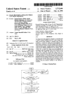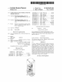
1
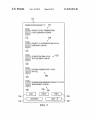
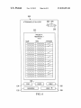
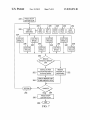
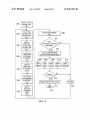
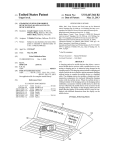
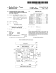
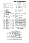
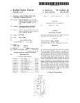
US008581876B1
(12) Ulllted States Patent
(10) Patent N0.:
Wickes et a].
(54)
(45) Date of Patent:
(72)
STAND ALONE ACTIVE STORAGE UNIT FOR
2005/0286225 A1 *
12/2005 Moore et a1. ................ .. 361/695
2006/0069840 A1 *
3/2006 Corbett et al. .............. .. 710/313
.
APPhCamSZDutch Eugene Wlckes, Palms’ TX
6/2008 Mel et al.
2008/0173598 Al*
7/2008
(US)
2010/0199023 A1 *
2011/0084845 A1 *
8/2010
4/2011
2011/0087825 A1
4/2011 Clahm et al'
20ll/0l6l688 Al*
2012/0159047 A1*
6/2011 Nonomura et al. ......... .. 713/300
6/2012 Li @1211. ................... .. 711/103
Subject to any disclaimer, the term ofthis
patent is extended or adjusted under 35
312/2232
Lee ....... ..
7ll/l03
et al. ............... .. 340/6361
2012/0206874 A1 *
8/2012
Huang
.. 36l/679.3l
2013/0075566 Al*
3/2013
Grant .... ..
.. 248/346.03
2013/0113727 A1*
2013/0166937 A1*
5/2013 Lin et al. .
..... .. 345/173
6/2013 Tu 61:11. ...................... .. 713/340
FOREIGN PATENT DOCUMENTS
Appl' NO‘: 13/911’642
(22)
Filed:
(60)
Related U's' Apphcatlon Data
Provisional application No, 61 /665,662, ?led on Jun,
28’ 2012'
DE
20200468 U1
Jun. 6, 2013
10/2002
OTHER PUBLICATIONS
-
-
HP, User Manual for HP TouchSmart IQ500 desktop PC, 2008*
B&H Photo and Electronics Corp., “The Professional’s Souce (TM)
for Photo, Video & Pro Audio,” product catalog, Summer, 2012, 3
pages, New York, NY.
(51) Int Cl
(58)
..... .. 439/607
7/2009 Moore ......... ..
(21)
(Continued)
i/041
' '
............... .. 2ll/4l.l2
2009/0179536 A1*
U.S.C. 154(b) by 0 days.
(52)
Fiorentino
(Us); Cheryl Dalton WllS0I1,Da11aS,TX
Inventors: Dutch Eugene Wickes, Dallas, TX
Notice:
2008/0155165 A1
2008/0261450 A1* 10/2008 Nguyen 61:11. .
Us _Ch
1]) It
W1
D 11
TX
gUsg’
cry
a on 1 son’ a as’
( * )
Nov. 12, 2013
MEMORY DEVICES
.
(71)
US 8,581,876 B1
(200601)
'
Primary Examiner * Koosha Shari?-Tafreshi
_
_
(74) Attorney, Agent, or Firm * Whitaker Chalk SWindle &
UISPC ......... .... ......
345/173, 361/679.31, 715/864
Fleld 0f Classl?catlon Search
USPC ........................ .. 345/173; 711/103, 115, 100;
361/679.31, 679.4, 679.32, 679.33;
206/307; 211/4112;
248/34603;
710/13; 715/864
See application ?le for Complete Search history'
(56)
References Cited
Schwartz PLLC; Stephen S‘ Mosher
(57)
An
ABSTRACT
,
M
d 1
d
.
.
a°‘_1V?’P°m1‘1 eastan a $96 .memoryl “If; 52mg‘? mm’
compnsmg a ousmg con almng a p'ura 1 0 memory
dev1ce receptacles, a touch sens1t1ve d1splay screen, and a
programmed processor c1rcu1t coupled to the plural1ty of
receptacles and the touch sensitive display. The unit provides
access to each memory device installed in a receptacle to
determine its identity, contents, capacity occupied, etc. and
U.S. PATENT DOCUMENTS
enables viewing the data stored on a memory device or trans
6,983,341 B1
8,050,713 B2
8,351,195 B2*
2001/0017989
A1 *
2004/0054863 A1 *
2005/0270063 A1 *
l/2006 Lim et al.
ll/20ll Ransom et al.
l/20l3
Huang .... ..
8/2001
Tamai et al.
3/2004 Harada et al.
12/2005
36l/679.3l
.....
. . . . . . ..
399/16
ferring portions of the data from one device memory device to
another, either inside or outside the storage unit, all Without
connecting the storage unit to a computer.
.. 711/164
Cornett ......................... .. 326/39
23 Claims, 11 Drawing Sheets
US 8,581,876 B1
Page 2
(56)
References Cited
freshiNFOS, “SanWa USB Reader lets you Jack a Mouse Into
OTHER PUBLICATIONS
Android Devices,” Jun. 13, 2012, 7 pages, http:/freshinfoscom.
Computer geekscom, “3-Port USB 2.0 Hub & Charger for iPhone
3gS/iPod (Black),” product Webpage, Jun. 13, 2012, 3 pages, WWW.
Wikipedia, “Digital Photo Frame,” Jun. 6, 2012, Webpage, 2 pages,
http://en.Wikipedia.org.
Digiframes, product Webpage, Jun. 6, 2012, 1 page, WWW.digiframes.
geekscom.
SIMCO Electronic Gifts Co., Ltd., “Product Name 4-Port USB Hub
com.
With Flashing Digital Photo Frame,” product Webpage, Jun. 13,
Mr. E. Tech., “i-FlashDrive USB Transfers Files to Apple Devices
2012, 2 pages, WWW.cccme.org.cn.
Without ITunes,” Webpage blog, Jun. 8, 2012, 1 page, http:/blog.
allusb.com.
* cited by examiner
US. Patent
Nov. 12, 2013
Sheet 1 0f 11
US 8,581,876 B1
20
US. Patent
Nov. 12, 2013
Sheet 3 0111
110%
US 8,581,876 B1
112
120
50TH BIRTHDAY PHOTOS "A" 6* PROJECT DRAWINGS "B"
1 GB FREE OF16 GB
1.205 FREE OF2GB
r114
@118
128
PRESENTATIONS "C"
2 5 GB FREE OF 5 GB
USB PORT "D"
OPEN PORT
i
MISC. FOLDERS "E"
FIELD REPORTS "F"
1 GB FREE OF 7,
.
_
HEAT CALCULATIONS "G"
_ .5 MB FREE OF 2 MB
102-’
A
SUMMER VACATION 2000 "H"
__.5 MBFREE OF 1 MB
MAINMENU J (
FIG. 3
BACK ) ]\
“108
US. Patent
Nov. 12, 2013
Sheet 4 0f 11
US 8,581,876 B1
140
PRESENTATIONS "c"
144
PRESENTATIONS PROJECT "A" 12/10/12
FOLDER 12,000 KB
142
W
148
/
WW
PROJECT "B" 2/1/13 LAST DATE MODIFIED
m
SLIDESHOW13,000 KB
146
W
152
/
m
m’
ATTENDEE LIST 3/1/13 LAST DATE MODIFIED
SPREADSHEET 10,000 KB
WW
m
NARRATIVE 3/1/13 LAST DATE MODIFIED
TEXT DOCUMENT 5,000 KB
154
156
MW
ATTENDEE LIST 3/1/13 STREAM
WWVW
PDF FILE
158
105
160
A COPY ] I PA\STE ] I PRINT ]\
104/
102/
\- 106
/I
MAINMENU
] I
FIG. 4
BACK D ]\
#108
US. Patent
Nov. 12, 2013
Sheet 5 0f 11
US 8,581,876 B1
170
PRESENTATIONS PROJECT "A"
MW
m
174
PROJECT "A" REV. PRESENTATION
11/3/12 SLIDESHOW 12,000 KB
172
178
/
WW
W
PROJECT "A" SD PRESENTATION 10/11/12
SLIDESHOW14,000 KB
m SDSPECIFICATIONS11/3/12
WWW
/182
TExT DOCUMENT5,000 KB
180
Mm EXTERIOR PERSPECTIVES 11/13/12
W PDF FILE
\
184
186
MW
m
18 8
PROGRAM REQUIREMENTS PROJECT "A" 3/11/12
SPREADSHEET 10,000 KB
105 \
\
190
A COPY ] I PASTE ] I PRINT }\ “106
A MAINMENU ] I
BACK ) }\
\- 108
FIG. 5
US. Patent
Nov. 12, 2013
Sheet 7 0f 11
US 8,581,876 B1
220\ PRESS ON/OFF
BUTTON TO ON
224
222\
W
DIsPLAY
MAIN MENU
234
I
\I
ICON FOR
SPACE A
236
V
__ MAIN
MENU
230
V /
PASTE
FIG. 9
V /
PRINT
FIG. 9
I
ICON FOR
SPACE C
ICON FOR
SPACE E
IcON FOR
SPACE G
24o
238
\
\ I
242
ICON FOR
SPACE D
I
244
\
I /
v
24a
246
IOON FOR
SPACE F
I
232
V /
BACK
FIGS. 3-6
I
ICON FOR
SPACE B
I
V /
COPY
FIG. 9
228
I
/
\ I
226
I, /
ICON FOR
SPACE H
I
I
250
REMOVE
OR INSTALL MEMORY
UNIT
I
INsTALL IN OPEN
262 / POsITION AND DISPLAY
OCCUPIED SPACE
DIsPLAY MEMORY UNIT
264 / ID AND OAPAOITY DATA
‘I:
RETURN
FINISHED?
/
256
PRESS ON/OFF
266/
268
BUTTON TO OFF
END
FIG. 7
REMOVE
AND DISPLAY \ 252
OPEN SPACE
|
US. Patent
NOV. 12, 2013
US 8,581,876 B1
Sheet 8 0f 11
SELECT, VIEW A
280 \ MEMORY UNIT
FIG. 3
TOUCH ICON
FOR
SELECTED
282 \
MEMORY UNIT
FIG. 3
SELECT PAGE DESIRED
FIG. 6
/ 294
I
COPY,
DISPLAY
DIRECTORY
284 \ OF SELECTED
MEMORY UNIT
FIG. 4
I
286\
I
288/
TOUCH CORRESPONDING
BUTTON TO PERFORM ACTION
TOUCH ICON
FOR FOLDER
OF INTEREST
FIG. 4
DISPLAY
DIRECTORY
OF SELECTED
FOLDER
FIG. 5
I
I
304
/
MAIN
MENU
306
I /
v/
312
I /
PASTE
FIG. 9
PRINT
FIG. 9
BACK
FIGS. 3-6
I
I
I
I
FINISHED?
NO
YES 314
PRESS ON/OFF BUTTON TO OFF
RETURN
\
I
316
DISPLAY
SELECTED
292/
310
308
V/
COPY
FIG. 9
I
TOUCH ICON
FOR DOCUMENT
290 / OF INTEREST
FIG. 5
NO
PASTE, BACK, PRINT OR
MAIN MENU‘?
318
DOCUMENT,
PAGE 1
FIG. 6
L_____
FIG. 8
320
US. Patent
Nov. 12, 2013
Sheet 9 0f 11
US 8,581,876 B1
COPY AND
PASTE OR PRINT
ACTION?
PR'NT
COPY AND PASTE
330 \
TOUCH COPY BUTTON
334
II‘
TOUCH ICON OF UNIT,
332
/
TOUCH PRINT BUTTON
L
\
"
I
FOLDER, OR DOCUMENT
TO BE COPIED OR PRINTED
SELECT
PORTION
360
" /
338
\
ENTIRE SELECTION
‘
366
/
SELECTED PORTION
RETURN
I
M
V‘
SELECT
DESTINATION
pRlNT
362
V
342 /
SELECT DESTINATION ICON
SELECT: TO PRINTER
344 /
TQUCH PASTE BUTTON
TRANSMIT TO
EXTERNAL PRINTER
<
I
\
364
FINISHED?
348
NO
PRESS ON/OFF BUTTGN TO OFF
350@
9
US. Patent
\ \ \§
440
Nov. 12, 2013
Sheet 10 0f 11
US 8,581,876 B1
US. Patent
Nov. 12, 2013
Sheet 11 0111
US 8,581,876 B1
US 8,581,876 B1
1
2
STAND ALONE ACTIVE STORAGE UNIT FOR
MEMORY DEVICES
accumulates. Further, each such element must still be con
nected electrically to the computer to learn its identity and
contents.
CROSS REFERENCE TO RELATED
APPLICATIONS
There is thus a need for a system or method of organiZing
a multiplicity of memory elements that overcomes the above
de?ciencies.
This application claims priority to US. Provisional Patent
Application Ser. No. 61/665,662 ?led Jun. 28, 2012 and
SUMMARY OF THE INVENTION
entitled STAND ALONE STORAGE UNIT FOR MEMORY
DEVICES.
In one embodiment, an active, portable, stand alone
memory device storage unit is provided, comprising a hous
ing, a plurality of memory device receptacles installed in a
surface of the housing, a touch sensitive display installed in an
outer surface of the housing adjoining the ?rst surface and
BACKGROUND OF THE INVENTION
1. Field of the Invention
The present invention generally relates to computing
operative to display a sequence of graphic displays including
devices and more particularly to stand alone apparatus for
in order a menu map of the memory device receptacles, a
storing a plurality of portable memory devices and capable of
directory of a compact memory device occupying a selected
displaying identi?cation and content information about the
stored elements.
2. Background of the Invention and Description of the Prior
memory device receptacle, and at least one content page of a
20
Art
Storage of obj ects containing information is Well knoWn in
the art. Libraries provide for storing books and other kinds of
objects that contain information. The libraries include cata
logs of the books stored on its shelves for users to determine
In another aspect the processor circuit further comprises a
?rst circuit for controlling the touch sensitive display in
response to a user selection entered upon the touch sensitive
25
What objects are stored there along With information about the
contents in each object listed in the catalog.
The advent of personal computers and the availability of
external plug-in devices containing memory readable by the
computer led to the need for Ways to store the external
memory devices When not in use. Memory devices in the form
30
35
installing the memory devices in an active stand alone
memory device storage unit having a plurality of receptacles
for the memory devices and a touch sensitive display screen
coupled to the plurality of receptacles; and displaying in a
main menu on the display screen a memory device icon
40
Even if an adapter having several USB ports is available the
task is not made easier. The dif?culty remains as to hoW to
determine the contents of the memory.
Heretofore such memory elements or devices must be
inserted into the computer or an accessory adapter or drive
unit to determine the identity and contents of the memory and
display, and a program responsive to the user selection, to
control display of information from at least one memory
device installed in a memory device receptacle, the informa
tion including a memory device identi?er and a receptacle
indicator associated With the memory device, and at least a
directory of the contents of the memory device.
In another embodiment, a method is provided for storing
and displaying contents of a plurality of compact memory
devices in a portable, stand alone device Without requiring
connection to a computing device, comprising the steps of
of magnetic tape, or magnetic or optical discs, and more
recently, miniature memory drives and semiconductor
memory devices such as thumb drives and the like can typi
cally can bene?t from some form of organiZed storage so that
a particular memory element or device can be conveniently
carried by a user and inserted into the computer to access its
contents. HoWever, users of portable memory elements often
encounter a tedious task to ?nd a particular unlabeled element
or to determine quickly the contents of a particular element,
When the computer has one or tWo USB ports, for example.
selected directory item, and a processor circuit coupled to the
plurality of receptacles and to the touch sensitive display and
enclosed Within the housing.
45
associated With each installed the memory device.
The method of the present invention further includes the
steps of touching a memory device icon on the display asso
ciated With an installed memory device to request display of
the contents of the memory device, displaying a directory of
the contents of the memory device on the display, touching
the display screen at a listing of the directory to select an item
corresponding to the listing for display on the display screen,
and displaying the selected item corresponding to the listing.
to access that contents. This is an inconvenience When many
such memory elements are accumulated, especially because
the memory elements themselves often contain no external
indicia of its identity or contents. Examples of these conven
tional adapters include an adapter to connect a USB ?ash
drive to an input port on the computing device such as a PC or
tablet or mobile telephone device. Some adapters include the
ability to connect several such ?ash drives to a computing
50
BRIEF DESCRIPTION OF THE DRAWINGS
55
FIG. 1 illustrates a pictorial, exploded-vieW diagram of a
?rst embodiment of the present invention;
FIG. 2 illustrates a block diagram of control circuitry for
the embodiment of FIG. 1;
FIG. 3 illustrates a graphic depicting one embodiment of a
device to access the ?ash drive. Adapters of this kind are not
Well-suited to storage of the ?ash drives and must be con
nected to a computer to determine the identity and content of
the ?ash drive. Providing a USB port receptacle in a comput
ing device is also not Well suited to storing an accumulation of
?ash drives or like memory elements and providing readouts
screen image upon activation of the embodiment of FIG. 1;
FIG. 4 illustrates a directory of contents of a selected
memory device connected to the embodiment of FIG. 1;
60
FIG. 1;
of any of the plurality of ?ash drive units a user may have
accumulated except to insert each ?ash drive into the recep
FIG. 6 illustrates a directory of contents of a selected
document in a selected folder of a memory device connected
tacle one-by-one. So-called “USB hubs” provide receptacles
for connecting several USB-compatible elements to one com
puter at the same time, but this again is not a satisfactory Way
to store such memory elements as the collection of them
FIG. 5 illustrates a directory of contents of a selected folder
in a selected memory device connected to the embodiment of
65
to the embodiment of FIG. 1;
FIG. 7 illustrates a ?oW chart for navigating a log-on dis
play of hub contents of the embodiment of FIG. 1;
US 8,581,876 B1
3
4
FIG. 8 illustrates a ?oW chart for operating the embodiment
of FIG. 1 in an instance of accessing a selected memory
detailed information such as speci?ed excerpts, etc. The
touch sensitive display enables selection of any particular one
device, folder, or document;
of the memory devices plugged into the system merely by
FIG. 9 illustrates a ?oW chart for “copy and paste,” to copy
a selected portion of a document, folder, or drive to another
touching the display at an icon associated With a particular
receptacle. Additional functions may be available to the user
according to a program instruction stored in the memory
associated With the processor circuit. Moreover, the system
may be preferably packaged in a variety of Ways. In the
present illustrative description the system is packaged as a
storage boxia portable and stand-alone unit for maximum
location;
FIG. 10 illustrates a second embodiment of the present
invention for use as a desk-top model; and
FIG. 1 1 illustrates a third embodiment of the present inven
tion for use as a pocket model.
utility, convenience, protection of private information, and
safety and security. The system may be constructed to permit
DETAILED DESCRIPTION OF THE INVENTION
locking of the container to alloW access only With a key or
combination code, thereby providing limited access to its
The invention described herein, a portable, stand alone
personal library system for storing compact memory devices
contents and function.
To summariZe the advantages of the invention, it provides
such as the popular and convenient “thumb drives” or “?ash
drives,” or any of a number of equivalent memory devices,
that are available noW or Will become available in the future.
For the purposes of this description, a compact memory
device (a “CMD” or just “memory device”) is usually (but not
so limited) a non-volatile memory unit implemented as semi
conductor memory con?gured as a semiconductor memory
chip, generally mounted on or manufactured as a circuit card
approximately the siZe of a postage stamp for convenient use
in small electronic devices such as a laptop computer, a
20
convenienceithe ability to quickly access and read the con
tents of several memory devices (e.g., ?ash or thumb drives)
Without having to locate a computer to plug them into. It is
portable, providing the user the ability to carry it With or on
his or her person. Since it can be locked and may be con
structed of heat, ?re, or Water proof materials, it provides
substantial security from damage by these elements. The
system described herein also provides privacy of the contents
mobile (e.g., cellular) phone, cameras, and other products
containing digital circuitry Where space is limited. Compact
of the memory devices and the ability to access and read the
data, because only the user can see the contents Without the
need to use any other device for accessing and vieWing the
memory devices are Well knoWn and readily available for
contents.
25
such products. One illustrative example featured in the
description is the Well-knoWn “?ash drive,” a compact, non
volatile memory packaged With a Universal Serial Bus
(“USB”) and connector (usually a male connector). This
compact memory device is ubiquitous in today’s market
because of its versatility, high capacity, ease of use, and
pocket siZe. As memory and communication technologies
develop, other compact memory devices, including those that
Although the embodiments illustrated in the included
30
Serial Bus)4compatible drives or the so-called ?ash or
thumb drives, the invention is not so limited to these particular
memory drives or elements, as any memory element that
employs a connector to interface With a computing device to
35
forth in the appended claims. The draWings illustrate an
exemplary embodiment and are not intended to limit the
invention to a single con?guration. Persons skilled in the art
40
The preferred embodiment described in FIGS. 1-9 depicts
a compact, portable system 10 for storing a plurality of
memory devices in a “library” or storage unit that permits
ready and convenient access to the memory devices Without
having to plug them into or otherWise connect them to a
computer system. The system includes the combination of
three sub-assembliesia plurality of memory device recep
tacles, a touch sensitive display screen (touch sensitive dis
play, or display assembly), and a processor circuit coupled to
the array of receptacles and the display. The processor circuit
controls access to, display of, and reading of the contents of
identify and read the element may utiliZe the apparatus and
method of the present invention as described herein and set
may be manufactured in technologies other than semiconduc
tors, may become available that provide the same advantages,
yet also are susceptible to storage in a system as described
herein.
draWings identify USB (the industry standard Universal
Will recogniZe other possible Ways to form the apparatus than
the ones depicted herein Without departing from the concept
of providing a stand-alone storage unit for a plurality of
memory devices that can be used for ascertaining the content
of each memory device Without having to connect it individu
45
ally With a computer system. Further, the system described
herein may be used to copy, paste, or print selectedportions of
the memory device content using the invention to be
described in detail beloW. In the description Which folloWs,
reference numbers appearing in more than one ?gure refer to
50 the same structures.
FIG. 1 illustrates a pictorial, exploded-vieW diagram of a
?rst embodiment of the present invention. The memory
the memory devices occupying the receptacles, as Well as
operations to copy, paste, and print selected portions of the
library and reader system 10 (“system 10”), Which may also
contents. The touch sensitive display provides an interface
be called a “Flash Box,” or a stand alone memory device
With the processor circuit to perform vieWing of directories,
documents, and control indicia for operating the functions
provided by the system. In one preferred but non-limiting
embodiment these elements may be enclosed in a housing,
chassis, or cabinet. The system may be self-contained and
may include ports or receptacles for connecting to external
55
60
devices such as a computer or printer, or to external poWer
system, and read out the identity and contents, for example
either as a table of contents, pages of a document, or more
and the processor circuit 16 coupled together and Which may
be housed in a housing or chassis 18, perhaps having a hinged
cover 20 attached to the chassis 18 by the hinge 60. The
system 10 may alternately be called a “memory hub 10,” the
receptacles 12 a “memory card 12,” and the processor circuit
16 a “motherboard 16.” The housing or chassis 18 may also be
called a “main frame 18.” The processor circuit 16 may be
sources to supply operating poWer or for charging an internal
battery.
Thus, the system provides a means by Which the user can
conveniently store his or her compact memory devices in the
storage unit, is shoWn in the ?gure. It includes the array of
receptacles 12, the touch sensitive display 14 (“display 14”),
65
connected to the plurality of receptacles 12 by a ?rst connec
tion component or cable 22 and to the display 14 by a second
connection component or cable 24. While cables 22, 24 may
be used in some embodiments, in other con?gurations the
US 8,581,876 B1
5
6
connection components 22, 24 may be replaced by connec
tors Without any intervening Wiring or cabling.
Continuing With FIG. 1, the depicted embodiment shows
shoWn in FIG. 10 to provide a maximum level of security
against damage by heat, ?re, or moisture.
FIG. 2 illustrates a simpli?ed block diagram of control
circuitry for the system shoWn in FIG. 1. A block for each of
the chassis 18 that is formed to have a memory bay 26 (analo
gous to the “stacks,” of a library), to provide space for the
the three main sub-assemblies 12, 14, and 16 is shoWn, along
With major internal components of each one. The receptacle
memory devices 30 plugged into individual receptacles 28
that are arrayed on the receptacle card 32. While the memory
receptacles 28 are shoWn as being all of the same type, it is
contemplated that the array 12 may include several types of
card 12 includes an array of individual memory device recep
tacles 28 that are coupled to the second connection compo
nent 24 via the circuit paths 34. The ?rst connection compo
nent 24 connects the receptacle card 12 to the motherboard or
processor circuit 16. The processor circuit 16 may include the
folloWing structures: a microprocessor or micro controller 80
(54 in FIG. 1), a random access memory (RAM) 82, a read
only memory (ROM) 84, a display controller 86, and a com
munication interface 88. In some implementations the micro
controller 80 may include the RAM 82, ROM 84, and the
receptacles to accommodate different types of memory
devices 30. The individual receptacles 28 may be supported
or mounted on a receptacle card or frame 32 that includes
receptacle circuit traces or paths 34 betWeen the receptacles
28 and the ?rst connection component 22. The system 10
depicted in FIG. 1 is provided With eight receptacles 28, but
this number is merely for purposes of illustration because the
number of receptacles may easily be varied to suit particular
circumstances. Further, the receptacle card 32 may support
operating system (“O/ S”) 90, or even the display controller 86
as internal components. As Well knoWn in the art, the ROM
84, Whether provided Within or separate from the micropro
other components such as an ON/OFF button 62, an external
poWer connection 64 (e.g., a battery charger or external
20
tion program (as described in FIGS. 7, 8, and 9) for control
ling the operating functions of the system 10.
Continuing With FIG. 2, the processor circuit 16 is prefer
ably coupled to the display 14 via the second connection
source), a connector 66 for providing a connection to an
external computer, printer, or other device for ?le transfer,
copying, or printing, or a USB connector 68 for use in charg
ing a battery from an external computer. In one non-limiting
example the receptacle card 32 may be a printed circuit board.
The receptacle card 32 may be enclosed Within a portion of
the chassis 18 as shoWn. These connection components 62,
25
component 22. It Will be understood that the ?rst 22 and
second 24 connection components may be cables or connec
tion receptacles or both, depending on the particular construc
tion required by the implementation. The display 14, as pre
64, 66, and 68 may be positioned to align With respective
openings 62A, 64A, 66A, and 68A provided in the chassis 18
as shoWn in FIG. 1.
cessor or micro controller 80, preferably includes an applica
30
viously described may include a touch screen 40 and a display
circuit 42. Other features of the system 10 that may be pro
The touch sensitive display 14 is shoWn as the uppermost
vided, for example but Without limitation, include certain
sub-assembly of the system 10 embodiment illustrated in
ports or connectors for connecting the processor circuit 16 to
an external battery (shoWn in dashed lines because it does not
FIG. 1. The touch screen 40, attached to a display board 42, is
shoWn With one embodiment of the graphics corresponding to
a main menu 100 (See FIG. 3 to be described) displayed
form part of the invention) via port 64; a USB (Universal
35
thereon. The display 14 may be coupled to the processor
circuit 16 by a second connection component 24 that connects
the display board 42 to the processor circuit 16. The touch
screen 40 should preferably be of a type that responds to the
Serial Bus) port 66 to provide a communication link to an
external device (also shoWn in dashed lines) such as a com
puter or printer; and another USB port 68 for connecting to an
external computer to access a remote recipient or destination
for a selected portion of the contents of a memory device
touch of a user’s ?nger, Whether it be a tap, a combination of
40 installed in the system 10, or even to access a source of
taps, a dragging or sliding motion along the surface of the
display, etc. for entering commands or otherWise interacting
With the system 10. The processor circuit 16 may include, in
addition to the circuitry (not shoWn in this vieW) associated
With operating the system 10 (to be described in FIG. 2), a
processor circuit board 50, a battery 52, and a micro controller
operating voltage for the system 10. Depicted on the touch
45
nal device. Alternatively, the communications interface may
or microprocessor 54.
The micro controller or microprocessor 54 may include
RAM and ROM as internal components or be associated With
external RAM 82 and ROM 84 (See FIG. 2). The processor
circuit 16 is shoWn in this illustrative vieW as being disposed
betWeen the display assembly 14 and the receptacle card 12.
include an optical transmitter and an output device for cou
pling the output of said transmitter to an optical transmission
line. Further, the communications interface 88 may be con
50
?gured through an internal program or additional structure to
enable connection to a computer to enable an alternative (but
not required) use of the system 10 as ?ash drive hub When
plugged into the computer. In this mode of operation, the
computer may be con?gured by the system 10 to present the
The three sub-assemblies may be enclosed as a compact
group Within the chassis 18. A cover 20 may be attached to a
rear side of the chassis 18 along a hinge 60. Although shoWn
screen 40 is one example of a main menu graphic display 100
to be described in FIG. 3.
The communications interface 88 may include an RF trans
mitter and antenna for Wireless communication With an exter
55
same sequence of displays as the screen provided on the
as an opaque cover, the cover 20 may include a transparent
system 10. Most computers are typically equipped With only
section or WindoW to vieW the touch screen 40 Without open
tWo USB ports, so the communications interface 88 Would
ing the cover 20. The cover 20 may also include graphics such
as a trade name, certain decorative features, and the like. The
abilities of the system 10. Because of their siZe, computers are
chassis 18 and cover 20 may be fabricated of sheet metal or
enable expansion of the capability of the computer via the hub
60
not as readily carried or transported as the ?rst and third
molded thermoplastic material. If the chassis 18 and cover 20
embodiments of the storage unit described herein.
are not made of metallic materials it may be necessary to
FIG. 3 illustrates a graphic depicting a screen image for a
main menu 100 upon activation of the embodiment of FIG. 1
provide shielding for the internal circuitry to comply With
Federal RF emissions requirements for electromagnetic inter
ference. Some embodiments may be con?gured for construc
tion of ?re-resistant materials or incorporated into ?re proof
or Water storage containers in the manner of the embodiment
65
by pressing the ON/OFF button 62 (See FIG. 1). The dis
played screen graphics may include images of icons repre
senting each memory device receptacle 28, Whether occupied
or not, and various commands to operate the system 10 or the
US 8,581,876 B1
7
8
functions performed by the system. Touching the screen 40
(See FIG. 1) at the location of an icon image selects that
“Presentations,” installed in the “C” position in the receptacle
card 12, includes a number of folders or other ?les designated
memory device or initiates a command or function repre
by the reference numbers 142, 146, 150, 154, and 158 in this
sented by the touched icon image. In some cases touching the
example. Each folder or ?le may be described by textual
screen 40 tWice or in tWo different locations, or dragging
and/or numeric indices respectively 144, 148, 152, 156, and
one’s ?nger mat be required and implemented in the operat
160 as shoWn in FIG. 4. For example, folder 142 entitled
ing or application program to initiate or perform the com
Presentations, Project “A,” is dated Dec. 10, 2012 and occu
pies 12,000 Kilobytes (KB) of memory space, as described by
the description indices 144. In another example, a PoWer
Point® ?le 146 entitled simply “Project B” is dated Feb. 1,
2013 and occupies 13,000 KB ofmemory space, as described
by the indices 148. Other entries in the device directory dis
play 140 include an Attendee List 150, Which may be, for
example, an Excel® spreadsheet 152, a Narrative 154/156,
mand or function (see FIGS. 7, 8, and 9). Included at the loWer
end of the screen 40, in most of the screen displays are a set of
command buttons for the functions MAIN MENU 102,
COPY 104, PASTE 105, PRINT 106, and BACK 108, all of
Which are Well-knoWn, intuitive commands. In addition, at
the upper end of the screen 40 may be an indicator 110 such
as an LED behind the screen or an image illuminated by a
and another Attendee List 158/160 in Adobe format. Note:
PowerPoint@ and Excel® are registered trademarks of
Microsoft® Corporation. Adobe is either a registered trade
mark or a trademark of Adobe Systems Inc. Touching the
light emitting device behind the screen 40 to indicate opera
tion of a battery charger, the condition of the battery, and the
like. Other indicators of this type may also be included in
alternate embodiments.
Also on the main menu display 100 in FIG. 3 are eight
icons, bearing reference numbers 124, 126, 128, 130, 132,
134, 136, and 138. Each icon 124-138 corresponds to one of
the receptacles 28 in the system 10 for receiving a memory
device 30 for storage in the system. When a memory device
receptacle 28 is occupied, the memory device icon 112 may
become illuminated, change color, or display an altered
image to indicate the occupation of the receptacle 28 in the
receptacle card 12. Each of these memory icons 112 may be
accompanied by a horiZontal bar graph image 114 that may
have a darkened (or colored) portion 116 representing an
occupied portion of the memory capacity of the memory
device 30 and an undarkened (or uncolored) portion 118
device directory display 140 at the location of the icon image
20
cases touching the directory display 140 tWice or in tWo
different locations, or dragging one’s ?nger is required to
initiate the command or function. As in screen 40 a set of
25
30
the directory of the contents of a selected folder 142 in a
selected memory device connected to the embodiment of
FIG. 1. The selected folder 142 entitled Presentations
include a number of documents 172, 176, 180, . . . 188,
respectively identi?ed by the indicia 174, 178, 182, . . . 190 in
of the memory device 30. For example, the bar graph 114 for
memory device 126 indicates 0.8 GB (giga byte) occupied
the same manner is described in FIG. 4. Touching the loWer
35
end of the display 170 at the location of a button image
initiates the corresponding command or function. In some
cases touching the folder directory display 170 tWice or in tWo
different locations, or dragging one’s ?nger from one indicia
to another is required to initiate the command or function. As
bar graph 114 may be a line of text 120 stating the name or
other identifying statement assigned to the memory device.
For example, memory device 126 is identi?ed as: Project
DraWings “B.” In another example, the text beloW the icon for
memory device 130, Which indicates that no memory device
command buttons for the functions MAIN MENU 102,
COPY 104, PASTE 105, PRINT 106, and BACK 108 may
appear at the loWer end of the device directory display 140.
FIG. 5 illustrates a folder directory display 170 depicting
“Project A,” is seen in the folder directory display 170 to
representing the remaining capacity (or unoccupied portion)
and 1.2 GB free. Also included in the screen display disposed
betWeen the memory device icon 112 and its corresponding
initiates the corresponding command or function. In some
40
in screen 40 a set of command buttons for the functions
MAIN MENU 102, COPY 104, PASTE 105, PRINT 106, and
30 is plugged into the corresponding receptacle 28, displays
BACK 108 may appear at the loWer end of the folder directory
the (default) statement: USB Port “D” and, in place of a bar
display 170.
graph 114, just the statement: Open Port. Other memory
device icons 112 for the receptacle ports 124 and 128, 132,
FIG. 6 illustrates a document display 200 depicting the ?rst
45
134, 136, and 138 have similar features as described in the
foregoing examples. These examples, not intended to be lim
iting, are provided to illustrate one embodiment for a main
menu display screen.
In operation, the user may install or remove a memory 50
device 30 from one of the receptacles 28. This action Will be
accompanied by a change to the memory device icon 112
corresponding to that particular receptacle 28, When the sys
tem 10 is turned on or activated. The change When a memory
device 30 is inserted into a vacant receptacle 28 on the recep
tacle card 12 may include the appearance of a line of text 120
55
102, COPY 104, PASTE 105, PRINT 106, and BACK 108
60
With an alpha numeric symbol such as the letters A, B, C, . . .
H, as shoWn in FIG. 3. Such indicating symbols may also be
used elseWhere in the system to relate the receptacle positions
to the main menu display, for example.
FIG. 4 illustrates a device directory display 140 depicting a
directory of contents of a selected memory device connected
to the embodiment of FIG. 1. The selected memory device,
from a selected folder, e.g., the Project A Presentation 172/
174 (See FIG. 5) of a compact memory device 30 connected
to a receptacle 28 in the receptacle card 12 of the embodiment
of FIG. 1. The page 1/4 may be indicated by the label 1/4 in
the upper right hand corner of the document display 200,
Which tracks the particular page selected by the user. Touch
ing the loWer end of the document display 200 at the location
of a button image initiates the corresponding command or
function. In some cases touching the document display 200
tWice or in tWo different locations, or dragging one’s ?nger is
required to initiate the command or function. As in screen 40
a set of command buttons for the functions MAIN MENU
indicating the identity of the memory device 30, and the
appearance of a bar graph image 114 to indicate the occupied
capacity 116 of that memory device 30. The observant reader
Will note that each memory device position may be identi?ed
page 1/4 of a selected document 202 such as anAttendee List
65
may appear at the loWer end of the document display 200.
FIG. 7 illustrates a How chart for navigating a log-on dis
play to access content stored in the system 10 illustrated in
FIG. 1. The process may begin at step 220 “press the ON/OFF
button 62.” The ON/OFF button 62 may be a push on/push off
sWitch, a toggle sWitch, or a rocker sWitch supported in the
chassis 18 as shoWn in FIG. 1, or even a touch sWitch inte
grated into the touch sensitive display screen 40. When turned
ON, the system 10 displays the main menu 100 that presents
US 8,581,876 B1
10
to the user several options for entering commands merely by
cuitry 16 reads the neW memory device 30 and displays the
identifying data about that memory device in the position of
an occupied icon on the screen display. In the next step 254,
the system requests the user to decide Whether to end the
touching the surface of the display screen 40 at the location of
a button icon that corresponds to the desired operation or
function. Options for the next step are provided by the step
222 display main menu, Which permits the display of the set
of icon images for the memory devices 30 corresponding to
the receptacles 28 (occupied or not) in the receptacle card 12.
session or return to step 222 as explained herein above.
FIG. 8 illustrates a How chart for operating the embodiment
of FIG. 1 in a sequence for accessing a document (or ?le) in
Also accessible from the main menu are icons for a set of
a selected folder from a selected memory device that is
command buttons for the functions MAIN MENU 102,
COPY 104, PASTE 105, PRINT 106, and BACK 108 that
may appear at the loWer end of the screen 40. Touching the
MAIN MENU button 102 in step 224, for example, returns
plugged into the system 10. The process begins at step 280
the screen display 40 to the main menu 100 as shoWn in FIG.
3. The MAIN MENU button 102 is useful When the user has
be selected in step 284. This step Will display the directory of
the selected memory unit (See FIG. 4). If this is the memory
completed an action With a particular memory device (FIG.
4), or folder (FIG. 5) or document (FIG. 6) and desires to
unit the user desires to access, in the next step 286 (See FIG.
4) the user may touch the icon for the folder of interest and the
With the main menu 100 displayed on the screen 40, that is, to
“Select, View a Memory Unit (See FIG. 3). In step 282 the
user may touch an icon corresponding to the memory unit to
return to the main menu 100 to initiate another action such as
display Will shoW the directory of the selected folder (See
accessing another memory device, etc.
Continuing With FIG. 7, touching the COPY button 104 in
FIG. 5) in step 288. In step 290 the user may touch an icon in
the directory of the selected folder to select a document or ?le
step 226 enables a command function for copying material
20
from one memory device/folder/ document to another as Will
be described in FIG. 9. Similarly, touching the PASTE button
106 in step 228 enables a command function for pasting
material into a destination memory device/folder/ document
as Will also be described in FIG. 9. Touching the PRINT
6) as indicated by the page number box 204. If it is desired to
advance to another page, touching the “forWard” button 205
25
button 105 in step 230 enables a command function for print
ing selected content of a memory device to an external printer,
as Will be described in FIG. 9. Touching the BACK button 108
in the document display 200 (to the right of the page number
label 204) on the screen 40 at step 294 (See FIG. 6) Will permit
the user to advance to the next page (one touch), to a farther
in step 232 provides for stepping back to the previous display
or step in the sequence illustrated in FIGS. 3 through 6.
Persons skilled in the art Will recogniZe that several of the
listed in the directory of the folder (See FIG. 5). Upon select
ing the document (or ?le), the screen 40 Will display the ?rst
page of the selected document (or ?le) in step 292 (See FIG.
30
functions performed as illustrated in FIGS. 7, 8, and 9 may be
implemented by con?guring the process to touch an icon and
then drag the user’s ?nger or stylus (if used but not shoWn
page (touch and hold button 205 until it scrolls to the desired
page, then release the touch). If it is desired to return to a
previous page, reverse the process of step 294 to return by
touching the “retum” button 203 in the document display 200.
Once a particular page of interest has been reached and
displayed during step 294, the user may choose one of the
several commands to COPY, PASTE, PRINT, BACK, or
herein) to transfer selected content of a selected compact
memory device from one memory device to another memory
device or other location. It is also to be understood that func
tions or commands other than the ones depicted and described
herein may be added or substituted Without departing from
35
return to the MAIN MENU, by touching the corresponding
the concepts of the present invention to meet other require
40
button on the document display 200 of the screen 40. The
decision step 300 alloWs the user to decide Whether to select
one of these functions by touching one of the button icons for
COPY 104, PASTE 105, PRINT 106, BACK 108, or to return
to the main menu 100 by touching MAIN MENU 102. Recall
that touching the BACK button 108 Will return to the previous
ments of a memory device storage system 10.
Continuing further With FIG. 7, at step 222 When the main
directory or to the main menu 100 if the user is at the memory
menu 100 is displayed, the user may next access any one of
directory 140. Touching the desired button in step 302
the memory device spaces 124,126,128, . . . , 138 by touching
the icon corresponding to the desired destination memory
device in a step selected from the set of steps 234, 236,
45
238, . . . , 248, Which respectively correspond to the memory
device spaces A, B, C, . . . , or H as shoWn in the ?gure.
Touching one of these buttons on the main menu 100 causes
the system 10 to change the display to the directory 140 of the
selected memory device, an example of Which is shoWn in
50
FIG. 9 illustrates a How chart for the COPY and PASTE or
step Where the user decides Whether to remove or install a
memory device 30 in a receptacle 28 of the system 10. If a
memory device 30 is to be removed as in step 252, the icon on
the main menu 100 changes to display an icon representing an
open memory space 130 as shoWn in FIG. 3. From there the
process advances to step 254, a decision step to determine
55
Whether the user is ?nished using the system 10. If NO, the
How proceeds to step 256 to return to display the main menu
display 40; if YES, the How advances to step 266 When the
60
PRINT functions to copy (or print) a selected portion of a
document, folder, or drive and to paste or transfer it in another
document, folder or memory device, or send it to a printer for
printing. The process begins at a decision step 328 folloWed
by the selection of the COPY & PASTE or PRINT function by
touching the COPY button icon 104 or the PRINT button 106
on the screen 40. This action may be performed on either of
user presses the ON/OFF sWitch to OFF and the process ends
memory device in step 262, Whereupon the processing cir
314 the user may press the ON/OFF sWitch 62 in step 316 and
the process ends in step 318. If the user is not ?nished (NO) in
step 314 the user may return in step 320 to re-enter step 282 at
the beginning of FIG. 8.
FIG. 4. This process Will be further described in FIG. 8.
Returning to FIG. 7, the How advances to step 250, a decision
at step 268. On the other hand, if, at step 250 the user decides
to install a memory device 30 in an unoccupied receptacle 28
the user locates an unoccupied receptacle 28, installs the
advances the process to the MAIN MENU in step 304, to the
process to COPY in step 306 (FIG. 9), to PASTE in step 308
(FIG. 9), to PRINT 310, or to BACK in step 312 (to one of
FIGS. 3-6 as applicable). If the user is ?nished (YES) in step
65
the displays for the memory device directory 100, the folder
directory 140, the document directory 170 or the selected
document 200. After touching the COPY button 104 in step
330, the How advances to step 334 in Which the user may
touch the icon of the memory device or unit, folder, or docu
ment to be copied. Step 334 leads to step 336 to determine
Whether the user Wishes to select all of the item or a portion of
the item to be copied. If ALL is selected in step 338, or a
US 8,58l,876 B1
11
12
PORTION is selected in step 360 the process advances to step
340 to select a destination of the copied item, Whether it is to
“COPY,” the user may select a memory device icon at the
devices 30 are plugged into USB receptacles 414 in the ?rst
bay 402 and eight USB memory devices 30 are plugged into
USB receptacles 414 of the second bay 404.
Operation of the system 400 is essentially identical as the
system 10 described herein above. Further, as noted previ
ously, the embodiment of FIG. 10 may be constructed in a
memory directory 100 in step 342 folloWed by touching the
variety of con?gurations. For example, in the arrangement,
PASTE button 106 to transfer the selected contents to the
spacing, and dimensions of the touch screen and the memory
device receptacle areas, the disposition of the various assem
blies Within the housing or cabinet may vary from that shoWn,
it being understood that many variations of the illustrated
combination are possible. Thus, a particular implementation
may appear different than that shoWn in FIG. 10 Without
COPY to a memory device in the system 10 via step 342 or
Whether it is to PRINT to an external printer via step 362.
Continuing With FIG. 9, if the destination selected is
destination memory device. Thereupon the How advances to
decision step 346 to determine Whether the user is FINISHED
executing the desired process. IfYES, the How steps to block
348 to press the ON/OFF sWitch to OFF and the routine ends
at step 350. If NO, the process advances to step 366 to return
to step 328, or, alternatively, the user may touch the BACK
departing from the concept and principles of the present
invention.
FIG. 1 1 illustrates a third embodiment of the present inven
108 or MAIN MENU 102 buttons to return to the screen 40
for further operations. Going back to the “Select destination”
step 340, if the user selected “PRINT,” the process advances
to step 362 to select a printer (or other external destination),
folloWed by selection of “Transmit to External Printer” in
step 364. The How then proceeds as previously described, to
END (step 350) or RETURN (step 366). The external desti
nation devices (not shoWn because they are not part of the
present invention) are accessible via the USB port 66 via the
tion for use as a pocket model. This system 500 is intended to
be functionally the same as the system 10 but may be
equipped With a smaller screen display and, in one non
20
system 500 and installed in a ?rst receptacle so that installa
tion of an occupied memory device in a second receptacle
communication interface 88 under the control of the process
ing circuit 16 (See FIG. 2). In other embodiments that include
may be processed to transfer some or all of its contents to the
25
an RF transmitter in the communications interface 88 as
described in FIG. 2, Wireless connection to external devices
Would be facilitated.
FIG. 1 0 illustrates one variation of a second embodiment of
the present invention for use as a desk-top model, Which
contains the same basic features and operation as the pre
30
“Thumb” drives or their equivalent. The receptacles 514, 516
35
may be recessed into the body of the case 540 for a smoother
appearance When a memory device 530, 532 is installed.
Receptacle 514 may be de?ned to receive a source memory
device 530 and receptacle 516 may be de?ned to receive a
destination memory device 532. The case 540 further prefer
ity of memory devices such as “Flash Drives” in a compact
the manner of the embodiment shoWn in FIG. 10 to provide a
ably includes a touch sensitive display screen 506 for display
ing a screen image 520 displaying the main menu graphic and
the same associated displays as shoWn in FIGS. 3, 4, 5, and 6
described herein. The system 500 may be con?gured to oper
40
8, and 9. Circuitry for the system 500 may be con?gured in a
except that the receptacle card 32 may be substantially
reduced in siZe or eliminated. In the latter case the receptacles
45
FIG. 11 are not shoWn in FIG. 11 because they Would be
FIG. 10 may include a ?reproof cabinet 440, constructed of
materials suitable for storage of the memory devices accom
50
Within a small ?re safe.
The desktop unit 400 depicted in FIG. 10 includes ?rst 402
and second 404 bays or galleries disposed on either side of a
55
screen 406. In the illustrated embodiment six USB memory
substantially identical to the corresponding embodiments
pictured in FIG. 1.
To summarize, described herein above is an active, stand
alone memory device storage unit, comprising a housing, a
plurality of memory device receptacles installed in a ?rst
surface of the housing, a touch sensitive display screen
installed in an outer surface of the housing in an adjoining
relationship With the ?rst surface. The unit provides portable
storage for a plurality of compact memory devices and is
414. The bays 402, 404 and screen 406 may be contained or
supported in a housing or cabinet 440. A processor circuitry
408 shoWn in dashed outline may be disposed Within the
cabinet 440 beloW the display screen 406. The cabinet 440
may have a lid 410 attached to the cabinet 440 along a hinge
412 and secured With a latch mechanism having a ?rst part
430 disposed on the lid 410 and a second corresponding part
432 disposed on the cabinet 440. The cabinet 440 may have
carrying handle 434 as shoWn. The system 400 may be acti
vated to display a main menu graphic 420 on the display
514, 516 may be directly coupled to the processor circuit 16
that is positioned just beneath the display assembly 14. The
processor circuit and display assembly in the embodiment of
moisture. For example, the desktop embodiment illustrated in
touch sensitive display screen assembly 406 and each bay
containing a plurality of sockets such as USB port receptacles
ate according to the same processes as described in FIGS. 7,
layered manner similar to the construction shoWn in FIG. 1
maximum level of security against damage by heat, ?re, or
modated by the storage unit described herein. Alternatively,
the storage unit may be siZed and shaped to ?t conveniently
unoccupied memory device, or simply stored in the system
500. The system 500 is designed to be pocket-siZed to facili
tate its use as a fully portable unit. The system 500 is housed
in a case 540 and includes ?rst 514 and second 516 recep
tacles for receiving ?rst 530 and second 532 USB “Flash” or
ferred embodiments described in FIGS. 1-9 that depict a
portable system 10. System 10 illustrates storage of a plural
“library” unit that permits ready and convenient access to the
memory devices Without having to plug them into or other
Wise connect them to a computer system. The desktop system
400 illustrated in FIG. 10 provides greater storage space for
memory devices (i.e., more “shelves” in the library) While
retaining the same ready and convenient access to “the
stacks” in the library as described herein above for the por
table system 10. Some embodiments of the present invention
may be con?gured for construction of ?re-resistant materials
or incorporated into ?re proof or Water storage containers in
limiting aspect, only tWo receptacles for memory devices.
One unoccupied memory device may be supplied With the
operative to display a sequence of graphic displays including
in order a menu map of the memory device receptacles, a
60
65
directory of each memory device occupying each selected
memory device receptacle in the unit, and at least one content
page of a selected directory item. The unit includes a proces
sor circuit coupled to the plurality of receptacles and to the
touch sensitive display screen and enclosed Within the hous
ing. The processor circuit further comprises a ?rst circuit for
controlling the touch sensitive display in response to a user
selection entered upon the touch sensitive display and a pro
US 8,581,876 B1
14
13
gram responsive to the user selection to control display of
a touch sensitive display installed in an outer surface of said
information from at least one memory device installed in one
housing adjoining said ?rst surface Wherein said stand
alone storage unit is operative Without requiring connec
of the memory device receptacles, the information including
a memory device identi?er and a receptacle indicator associ
ated With the memory device, and at least a directory of the
tion to a computing device to display a sequence of
graphic displays including in order a menu map of said
memory device receptacles, a directory of a compact
memory device occupying a selected memory device
contents of the one memory device.
There is also described herein a method for storing and
displaying contents of a plurality of compact memory devices
in an active stand alone memory device storage unit Without
requiring connection to a computing device. The method
begins With the step of installing the memory devices in the
active stand alone memory device storage unit that has a
plurality of receptacles for the memory devices and a touch
sensitive display screen coupled to the plurality of recep
tacles. The method further includes the steps of displaying in
receptacle, and at least one content page of a selected
directory item; and
a processor circuit coupled to said plurality of receptacles
and to said touch sensitive display and enclosed Within
said housing, said processor circuit further comprising:
a ?rst circuit for controlling said touch sensitive display in
response to a user selection entered upon said touch
sensitive display; and
a main menu on the display screen a memory device icon
a program responsive to said user selection, to control
display of information from at least one said memory
device installed in one of said memory device recep
associated With each installed memory device, touching a
memory device icon on the display associated With an
installed memory device to request display of the contents of
said memory device, displaying a directory of the contents of
said memory device on said display, touching the display
20
screen at a listing of the directory to select an item corre
sponding to the listing for display on the display screen, and
displaying the selected item corresponding to the listing.
Scenarios in the use of the system described herein include
but are not limited to the folloWing. For example, if a user
Wishes to give or transfer information to another person the
information can be selected and transferred to a ?ash drive
provided by the recipient. Also, the invention alloWs a user to
leave his or her of?ce With, e.g., several ?ash drives of infor
25
receptacle; and
an array of user touch-selection images corresponding to
30
3. The storage unit of claim 2, said graphic images com
aWay from the o?ice, for use in meetings, presentations, and
the like. Further, While traveling, the storage device can be
except the user.
In use, other examples of use include the ability to access
the table of contents of a ?ash drive to obtain more complete
information than could be Written on a label small enough to
be attached to the ?ash drive, Which is a very small device.
Thus, the contents can be accessed and read independently of
any other device such as a laptop or other computer. Further,
the system of the present invention can be used as ?ash drive
hub When plugged into a computer and connected via the
communications interface. And, as described herein, the sys
prising:
35
40
45
50
7. The storage unit of claim 2, said touch-selection images
55
ing of copy, paste, print, main menu, and back.
8. The device of claim 1, said processor circuit further
comprising:
ceiver, so that storage boxes could communicate, that is,
devices, comprising:
a housing;
a plurality of memory device receptacles installed in a ?rst
surface of said housing;
comprising:
at least one button image selected from the group consist
to include in the communications interface 88 (See FIG. 2) an
RF or optical receiver or, alternatively, an RF or optical trans
What is claimed is:
1. An active, stand alone storage unit for compact memory
a memory device having small siZe and a communication
interface and connector.
6. The storage unit of claim 5, said memory device com
a non-volatile semiconductor memory, and a USB inter
face and connector.
forms, it is not thus limited but is susceptible to various
another similarly equipped system 10.
title of said document, a date of entry into said memory
device, and a siZe of said document stated in numeric
units.
5. The storage unit of claim 1, Wherein said compact
prising:
loosely accumulated in a box or bag, or pocket or purse.
While the invention has been shoWn in only one of its
transfer ?les from a memory device in one system 10 to
indicator of memory unoccupied in saidmemory device.
4. The storage unit of claim 1, said directory comprising:
a graphic display including a document identifying icon, a
memory device comprises:
device or printer. Another advantage is that the ?ash drives are
changes and modi?cations thereof Without departing from the
spirit, concepts, and principles of the invention as set forth in
the appended claims. One such modi?cation, for example, is
displayed data corresponding to each said memory device
receptacle selected from the group consisting of a sym
bol representing a said memory device receptacle, a title
of a memory device occupying a said memory device
receptacle, a bar graph of memory capacity, an indicator
of memory occupied in said memory device, and an
tem can copy the entire ?ash drive contents or selected indi
vidual ?les from one ?ash drive to another or to an external
securely stored in the respective receptacles instead of being
user-entered commands for controlling said storage
device.
mation or data and have convenient access to them While
locked or, in some embodiments, secured from damages due
to heat, ?re, Water, etc. Moreover, the system bars access to
the memory devices stored in the storage container by anyone
tacles, said information including a memory device
identi?er and a receptacle indicator associated With said
memory device, and at least a directory of the contents of
said memory device.
2. The storage unit of claim 1, said menu map comprising:
a main menu of graphic images corresponding to the opera
tive status of each said memory device receptacle and of
each said memory device occupying a memory device
60
a communication interface circuit including an output port
for communicating contents of a selected memory
device to an external peripheral or computing device.
9. The storage unit of claim 8, said communication inter
face circuit comprising:
a Wireless transmitter coupled to an output port; and
a driver circuit for coupling an output signal of said trans
mitter to an antenna or a transmission line.