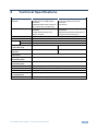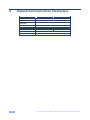
1
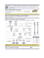
K R A ME R E LE CT R O N IC S L TD . USER MANUAL MODELS: VA-1USB-T USB Transmitter VA-1USB-R USB Receiver P/N: 2900-300209 Rev 3 Contents 1 Introduction 1 2 2.1 2.2 2.3 2.4 Getting Started Achieving the Best Performance Safety Instructions Recycling Kramer Products Shielded Twisted Pair/Unshielded Twisted Pair 2 2 3 3 3 3 Overview 4 4 4.1 4.2 Defining the VA-1USB-T and VA-1USB-R USB Transmitter and Receiver Defining the VA-1USB-T USB Transmitter Defining the VA-1USB-R USB Receiver 5 5 6 5 5.1 5.2 5.3 5.4 Connecting the VA-1USB-T and VA-1USB-R Connecting to the product via RS-232 Setting the Device ID DIP-switch Resetting the VA-1USB-T to Factory Default Settings Resetting the VA-1USB-R to Factory Default Settings 8 10 10 11 11 6 6.1 6.2 6.3 6.4 7 Using the Web Pages Accessing the VA-1USB-T/VA-1USB-R Embedded Web Pages The System Tab The Network Tab The Functions Tab Wiring the Twisted Pair RJ-45 Connectors 12 12 13 15 16 18 8 Technical Specifications 19 9 Default Communication Parameters 20 Figures Figure 1: VA-1USB-T USB Transmitter Front Panel Figure 2: VA-1USB-T USB Transmitter Rear Panel Figure 3: VA-1USB-R USB Receiver Front Panel Figure 4: VA-1USB-R USB Receiver Rear Panel Figure 5: Connecting the VA-1USB-T Transmitter and VA-1USB-R Receiver Figure 6: Machine ID DIP-switch Figure 7: Entering the IP Address in your Browser Figure 8: Main Page System Tab Figure 9: System Tab Figure 10: Update Firmware Window Figure 11: Warning Message Figure 12: The Network Tab Figure 13: Warning Message Figure 14: The Functions Tab Figure 15: Warning Message Figure 16: TP Pinout Wiring 5 6 7 7 8 10 12 12 13 14 15 15 15 16 17 18 VA-1USB-T/VA-1USB-R – Contents i 1 Introduction Welcome to Kramer Electronics! Since 1981, Kramer Electronics has been providing a world of unique, creative, and affordable solutions to the vast range of problems that confront video, audio, presentation, and broadcasting professionals on a daily basis. In recent years, we have redesigned and upgraded most of our line, making the best even better! Our 1,000-plus different models now appear in 11 groups that are clearly defined by function: GROUP 1: Distribution Amplifiers; GROUP 2: Switchers and Routers; GROUP 3: Control Systems; GROUP 4: Format/Standards Converters; GROUP 5: Range Extenders and Repeaters; GROUP 6: Specialty AV Products; GROUP 7: Scan Converters and Scalers; GROUP 8: Cables and Connectors; GROUP 9: Room Connectivity; GROUP 10: Accessories and Rack Adapters and GROUP 11: Sierra Video Products. Thank you for purchasing the Kramer MegaTOOLS® VA-1USB-T USB Transmitter and VA-1USB-R USB Receiver which are ideal for: Presentation and multimedia applications Long range USB distribution for schools, hospitals, stores and security installations Each package includes the following items: VA-1USB-T USB Transmitter and VA-1USB-R USB Receiver 2 Power adapters (5V DC) IR Blaster cable This user manual VA-1USB-T/VA-1USB-R - Introduction 1 2 Getting Started We recommend that you: Unpack the equipment carefully and save the original box and packaging materials for possible future shipment Review the contents of this user manual i 2.1 Go to http://www.kramerelectronics.com/support/product_downloads.asp to check for up-to-date user manuals, application programs, and to check if firmware upgrades are available (where appropriate). Achieving the Best Performance To achieve the best performance: Use only good quality connection cables (we recommend Kramer highperformance, high-resolution cables) to avoid interference, deterioration in signal quality due to poor matching, and elevated noise levels (often associated with low quality cables) Do not secure the cables in tight bundles or roll the slack into tight coils Avoid interference from neighboring electrical appliances that may adversely influence signal quality Position your Kramer VA-1USB-T and VA-1USB-R away from moisture, excessive sunlight and dust ! 2 This equipment is to be used only inside a building. It may be connected only to other equipment that is installed inside a building VA-1USB-T/VA-1USB-R - Getting Started 2.2 Safety Instructions ! 2.3 Caution: No operator serviceable parts inside the unit Warning: Use only the Kramer Electronics input power wall adapter that is provided with the unit Warning: Disconnect the power and unplug the unit from the wall before installing Recycling Kramer Products The Waste Electrical and Electronic Equipment (WEEE) Directive 2002/96/EC aims to reduce the amount of WEEE sent for disposal to landfill or incineration by requiring it to be collected and recycled. To comply with the WEEE Directive, Kramer Electronics has made arrangements with the European Advanced Recycling Network (EARN) and will cover any costs of treatment, recycling and recovery of waste Kramer Electronics branded equipment on arrival at the EARN facility. For details of Kramer’s recycling arrangements in your particular country go to our recycling pages at http://www.kramerelectronics.com/support/recycling/. 2.4 Shielded Twisted Pair/Unshielded Twisted Pair We recommend that you use Shielded Twisted Pair (STP) cable and stress that the compliance to electromagnetic interference was tested using STP cable. There are different levels of STP cable available and we advise you to use the best quality STP cable that you can afford. For the VA-1USB-T and VA-1USB-R pair we recommend the use of shielded, twisted pair (STP), non-skew-free Kramer BC-STP cable. VA-1USB-T/VA-1USB-R - Getting Started 3 3 Overview The VA-1USB-T and VA-1USB-R are a high-performance, TP (Twisted Pair) transmitter and receiver for communicating USB, bidirectional RS-232 data and unidirectional IR signals over extended distances using CAT 5/6 cable. The VA-1USB-T encodes USB signals and RS-232 data and transmits them over CAT 5/6 cable as a TP signal. The VA-1USB-R decodes the signal from the TP into USB signals and RS-232 data. The VA-1USB-R also acts as a 4-port USB hub and receives IR signals for transmission back to the VA-1USB-T. More specifically, the VA-1USB-T and VA-1USB-R support: 4 USB 2.0 high speed and USB 1.1 signals (bulk mode, not isochronous) True Plug and Play operation without drivers All major operating systems Full duplex, bidirectional RS-232 transmission Local and remote control of devices via the serial port Operation up to 100m (328ft) apart Web pages for maintenance and configuration Automatic Ethernet speed selection Up to 16 independent pairs of devices on a single network VA-1USB-T/VA-1USB-R - Overview 4 Defining the VA-1USB-T and VA-1USB-R USB Transmitter and Receiver This section defines the: 4.1 VA-1USB-T USB Transmitter (see Section 4.1) VA-1USB-R USB Receiver (see Section 4.2) Defining the VA-1USB-T USB Transmitter In addition to encoding and transmitting the USB and RS-232 signals, the VA-1USB-T outputs the IR signal received from the VA-1USB-R. RS-232 commands and data flow bidirectionally allowing status requests and control of a destination unit. Figure 1 defines the front panel of the VA-1USB-T. Figure 1: VA-1USB-T USB Transmitter Front Panel # Feature Function 1 IR OUT 3.5mm Mini Jack Connect the IR blaster 2 RS-232 9-pin D-sub Serial Port Connector (F) Connect to the serial controller Note: The RS-232 link is bidirectional 3 RESET Button Press to reset the device to factory default (see Section 5.3) 4 LINK LED Lights green when the TP link to the receiver is established 5 ON LED Lights green when the device is powered on VA-1USB-T/VA-1USB-R - Defining the VA-1USB-T and VA-1USB-R USB Transmitter and Receiver 5 Figure 2 defines the rear panel of the VA-1USB-T. Figure 2: VA-1USB-T USB Transmitter Rear Panel # Feature Function 6 USB HOST INPUT Type B USB Connector Connect to a USB host (see Section 5) 7 CAT 5/6 OUT RJ-45 Connector Connect to the CAT 5/6 IN RJ-45 connector on the VA-1USB-R (see Section 2.4) 8 MACHINE ID 4-way DIP-switch Use to set the device ID to pair with the receiver (see Section 5.2) 9 5V DC Power Connector Connect to one of the supplied +5V DC power adapters. Center pin positive 4.2 Defining the VA-1USB-R USB Receiver The VA-1USB-R decodes the USB signal and RS-232 data from the TP link sent from the VA-1USB-T. The receiver distributes the USB signal across four USB ports (acting as a USB hub) and outputs the RS-232 data. The VA-1USB-R receives an IR signal via its IR sensor and sends it over the TP link to the VA-1USB-T. Figure 3 defines the front panel of the VA-1USB-R. 6 VA-1USB-T/VA-1USB-R - Defining the VA-1USB-T and VA-1USB-R USB Transmitter and Receiver Figure 3: VA-1USB-R USB Receiver Front Panel # Feature Function 1 IR Sensor Receives IR signals from an IR transmitter 2 USB DEVICES 1~4 Type A USB Connectors Connect to up to four USB devices 3 4 LINK 5 ON LED Button Press to establish the TP link to the transmitter LED Lights green when the TP link to the transmitter is established Lights green to indicate that the device is powered on Figure 4 defines the rear panel of the VA-1USB-R. Figure 4: VA-1USB-R USB Receiver Rear Panel # Feature Function 6 CAT 5/6 IN RJ-45 Connector Connect to the CAT 5/6 OUT RJ-45 connector on the rear panel of the VA-1USB-T (see Section 2.4) 7 RS-232 9-pin D-sub Serial Port Connector (F) Connect to the device to be controlled via the serial link. Note: The RS-232 link is bidirectional 8 MACHINE ID 4-way DIP-switch Use to set the device ID to pair with the transmitter (see Section 5.2) 9 5V DC Power Connector Connect to one of the supplied +5V DC power adapters. Center pin positive VA-1USB-T/VA-1USB-R - Defining the VA-1USB-T and VA-1USB-R USB Transmitter and Receiver 7 5 Connecting the VA-1USB-T and VA-1USB-R i Switch off the power to all devices before connecting them to your VA-1USB-T/VA-1USB-R. After connecting your VA-1USB-T/ VA-1USB-R, connect the power to the transmitter and receiver and then switch on the power to the other devices. Figure 5: Connecting the VA-1USB-T Transmitter and VA-1USB-R Receiver 8 VA-1USB-T/VA-1USB-R - Connecting the VA-1USB-T and VA-1USB-R To connect the VA-1USB-T and the VA-1USB-R as illustrated in the example in Figure 5: 1. On the VA-1USB-T, connect: The USB host, (for example, a computer) to the USB Host Input connector The RS-232 controller, (for example, a laptop controller with an RS-232 interface) to the RS-232 9-pin D-sub connector An IR blaster to the IR 3.5mm mini jack 2. On the VA-1USB-R, connect: The first USB Devices port to a USB hard drive The second USB Devices port to a multimedia player The fourth USB Devices port to a USB flash storage device 3. Using STP cabling, connect the CAT 5/6 Out RJ-45 connector on the VA-1USB-T to the CAT 5/6 In RJ-45 connector on the VA-1USB-R (see Section 2.4). 4. Set the machine ID on both devices to the same ID using the Machine ID DIP-switch (see Section 5.2). 5. Connect the power adapters to the power sockets on the VA-1USB-T and VA-1USB-R, and plug the adapters into the mains electricity (not shown in Figure 5). 6. Establish a TP link by pressing the Link button on the receiver. VA-1USB-T/VA-1USB-R - Connecting the VA-1USB-T and VA-1USB-R 9 5.1 Connecting to the product via RS-232 You can connect to the VA-1USB-T/VA-1USB-R via an RS-232 connection using, for example, a PC. Note that a null-modem adapter/connection is not required. To connect to the VA-1USB-T/VA-1USB-R via RS-232: Connect the RS-232 9-pin D-sub port on the VA-1USB-T/VA-1USB-R via a 9-wire, straight cable (only pin 2 to pin 2, pin 3 to pin 3, and pin 5 to pin 5 need to be connected) to the RS-232 9-pin D-sub port on your PC 5.2 Setting the Device ID DIP-switch The Device ID DIP-switch is used on both the VA-1USB-T transmitter and VA-1USB-R receiver to set matching device numbers. This allows up to 16 pairs of transmitters and receivers to communicate independently on the same TP subnet. Figure 6: Machine ID DIP-switch Set each device in a transmitter and receiver pair to the same device ID according to the following table. Press a switch up to turn it on and down to turn it off. Switch Number 1 2 3 4 0 (default) Off Off Off Off 1 Off Off Off On 2 Off Off On Off 3 Off Off On On 4 Off On Off Off 5 Off On Off On 6 Off On On Off 7 Off On On On 8 On Off Off Off 9 On Off Off On Device ID 10 VA-1USB-T/VA-1USB-R - Connecting the VA-1USB-T and VA-1USB-R Switch Number 1 2 3 4 10 On Off On Off 11 On Off On On 12 On On Off Off 13 On On Off On 14 On On On Off 15 On On On On Device ID 5.3 Resetting the VA-1USB-T to Factory Default Settings To reset the VA-1USB-T to factory default settings: 1. Turn off the power to the device. 2. Press and hold the Reset button while turning on the power to the device. 3. When the Link LED starts to flash, release the Reset button. The device is reset to factory default settings. 5.4 Resetting the VA-1USB-R to Factory Default Settings To reset the VA-1USB-R to factory default settings: 1. Turn off the power to the device. 2. Press and hold the Link button while turning on the power to the device. 3. When the Link LED starts to flash, release the Link button. The device is reset to factory default settings. VA-1USB-T/VA-1USB-R - Connecting the VA-1USB-T and VA-1USB-R 11 6 Using the Web Pages The VA-1USB-T and VA-1USB-R provide built-in Web pages accessible by standard Web browsers that allow you to configure and maintain the devices. 6.1 Accessing the VA-1USB-T/VA-1USB-R Embedded Web Pages Before you can use the embedded Web pages, check that your computer is correctly connected to the VA-1USB-T/VA-1USB-R via the Ethernet connection. To access the VA-1USB-T/VA-1USB-R embedded Web pages: 1. Open your Internet browser. 2. Type the IP address (see Section 9) of the VA-1USB-T/VA-1USB-R in the address bar of your browser. (The IP address for the VA-1USB-T is shown, for the IP address of the VA-1USB-R see Section 8). Figure 7: Entering the IP Address in your Browser The screen shown in Figure 8 appears. Figure 8: Main Page System Tab 12 VA-1USB-T/VA-1USB-R - Using the Web Pages The Web pages consist of the following tabs: 6.2 System tab (see Section 6.2) Network tab (see Section 6.3) Functions tab (see Section 6.4) The System Tab Using the System tab (Figure 9) you can: View the version information Update the firmware Run functions Figure 9: System Tab To update the firmware: 1. Click on Update Firmware. The window shown in Figure 10 is displayed. VA-1USB-T/VA-1USB-R - Using the Web Pages 13 Figure 10: Update Firmware Window 2. Click on Browse. The Windows Browser is displayed. 3. Browse to the new firmware file location. 4. Select the new firmware file. 5. Click OK. The name of the new firmware file is displayed in the Update Firmware window. 6. Click on Upload. The update starts. Warning: Do not turn off or in any way interrupt the update process as this may cause the device to become inoperable. 7. When the process is complete, reboot the device (as indicated by the message shown in Figure 11) by clicking on Utilities and clicking Reboot. The device is rebooted with the new firmware. 14 VA-1USB-T/VA-1USB-R - Using the Web Pages Figure 11: Warning Message 6.3 The Network Tab Using the Network tab (Figure 12), you can modify the IP parameters of the device. Currently only static IP addressing is allowed. Figure 12: The Network Tab To change the IP parameters: 1. Click on the Network tab. The window shown in Figure 12 is displayed. 2. Modify the IP address, subnet mask and default gateway addresses as required. 3. Click Apply. The changes are made and the message shown in Figure 13 is displayed. Figure 13: Warning Message VA-1USB-T/VA-1USB-R - Using the Web Pages 15 4. Reboot the device by clicking on Utilities and clicking Reboot. The device is rebooted with the new IP parameters. 6.4 The Functions Tab Using the Functions tab (Figure 14) you can enable/disable and modify the serialover-IP parameters. Figure 14: The Functions Tab To modify the serial-over-IP functionality: 1. Click on the Functions tab. The window shown in Figure 14 is displayed. 2. Enable or disable the device by checking or unchecking the Enable Serial over IP box. 3. Modify the serial communication parameters using the drop-down lists for Baud rate, Data bits, Parity and Stop bits. 4. Click Apply. The changes are made and the message shown in Figure 15 is displayed. 16 VA-1USB-T/VA-1USB-R - Using the Web Pages Figure 15: Warning Message 5. Reboot the device by clicking on Utilities and clicking Reboot. The device is rebooted with the new IP parameters. VA-1USB-T/VA-1USB-R - Using the Web Pages 17 7 Wiring the Twisted Pair RJ-45 Connectors When using STP cable, connect/solder the cable shield to the RJ-45 connector shield. Figure 16 defines the TP pinout using a straight pin-to-pin cable with RJ-45 connectors. PIN 1 18 EIA /TIA 568B Wire Color Orange / White 2 Orange 3 Green / White 4 Blue 5 Blue / White 6 Green 7 Brown / White 8 Brown Pair 1 4 and 5 Pair 2 Pair 3 1 and 2 3 and 6 Figure 16: TP Pinout Wiring VA-1USB-T/VA-1USB-R - Wiring the Twisted Pair RJ-45 Connectors 8 Technical Specifications VA-1USB-T INPUTS: VA-1USB-R USB SUPPORT: 1 USB host on a USB Type B 1 TP CAT 5/6 IN on an RJ-45 connector connector 1 Bidirectional RS-232 serial port 1 IR sensor on a 9-pin D-sub connector (F) 1 TP CAT 5/6 OUT on an RJ-45 4 USB devices on USB Type A connector connectors 1 Unidirectional IR port on a 1 Bidirectional RS-232 serial port on 3.5mm mini jack a 9-pin D-sub connector (F) 1.1 and 2.0 (bulk mode, not isochronous) ETHERNET SPEED: 100/1000Mbps automatic selection RS-232: BAUD RATE: Up to 115200bps MODE: Full-duplex 5V DC 800mA OUTPUTS: POWER CONSUMPTION: MAXIMUM POWER OUTPUT: TRANSMISSION DISTANCE: OPERATING TEMPERATURE: STORAGE TEMPERATURE: HUMIDITY: DIMENSIONS: WEIGHT: INCLUDED ACCESSORIES: OPTIONS: 5V DC 2.8A 5V 500mA per USB port Up to 100m (328ft) 0° to +40°C (32° to 104°F) –40° to +70°C (–40° to 158°F) 10% to 90%, RHL non-condensing 12.1cm x 7.18cm x 2.42cm (4.76" x 2.83" x 0.95"), W, D, H 0.44kg (0.97lbs.) approx. each 2 Power supplies RK-T2B 19” rack adapter VA-1USB-T/VA-1USB-R - Technical Specifications 19 9 Default Communication Parameters RS-232 VA-1USB-T Baud Rate: VA-1USB-R 115200 Data Bits: 8 Stop Bits: 1 Parity: None Ethernet IP Address: Network Mask: Default Gateway: 20 192.168.1.39 192.168.1.40 255.255.255.0 192.168.1.1 VA-1USB-T/VA-1USB-R - Default Communication Parameters This page is intentionally left blank For the latest information on our products and a list of Kramer distributors, visit our Web site where updates to this user manual may be found. We welcome your questions, comments, and feedback. Web site: www.kramerelectronics.com E-mail: [email protected] ! SAFETY WARNING Disconnect the unit from the power supply before opening and servicing P/N: 2900- 300209 Rev: 3