1
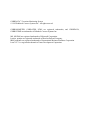
Serial Number _____________
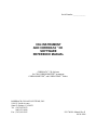
CK4 INSTRUMENT
AND CORRDATA™ CK
SOFTWARE
REFERENCE MANUAL
CORRDATA™ CK Software
for CK4 CORROSOMETER® instrument,
CORROSOMETER®, and CORROTEMP™ Probes
ROHRBACK COSASCO SYSTEMS, INC.
11841 E. Smith Avenue
Santa Fe Springs, CA 90670
Tel: (562) 949-0123
(800) 635-6898
Fax: (562) 949-3065
P/N 700901-Manual Rev E
08-28-2008
CORRDATA™ Corrosion Monitoring System
© 1992 Rohrback Cosasco Systems Inc. All rights reserved.
CORROSOMETER, CORRATER, ICMS are registered trademarks, and CORRDATA,
CORROTEMP are trademarks of Rohrback Cosasco Systems Inc.
MS, MS-DOS are registered trademarks of Microsoft Corporation.
Laserjet, paintjet are registered trademarks of Hewlett-Packard Company.
IBM, proprinter are registered trademarks of International Business Machines Corporation
Lotus 1-2-3 is a registered trademark of Lotus Development Corporation.
Contents
Chapter 1
Introduction . . . . . . . . . . . . . . . . . . . . . . . . . . . . . . . . . 1
Chapter 2 Specifications . . . . . . . . . . . . . . . . . . . . . . . . . . . . . . . . 5
CK4 CORROSOMETER Instrument . . . . . . . . . . . . . . . . . . . . . . . . . . . . . . . . . . 5
P.C. Requirements . . . . . . . . . . . . . . . . . . . . . . . . . . . . . . . . . . . . . . . . . . . . . . . . . 6
Chapter 3 Installation . . . . . . . . . . . . . . . . . . . . . . . . . . . . . . . . . . . 7
Unpacking . . . . . . . . . . . . . . . . . . . . . . . . . . . . . . . . . . . . . . . . . . . . . . . . . . . . . . . 7
Intrinsic Safety . . . . . . . . . . . . . . . . . . . . . . . . . . . . . . . . . . . . . . . . . . . . . . . . . . . . 7
CK4 CORROSOMETER Instrument . . . . . . . . . . . . . . . . . . . . . . . . . . . . . . . . . . 8
CORRDATA CK P.C. Software . . . . . . . . . . . . . . . . . . . . . . . . . . . . . . . . . . . . . 11
Chapter 4 System Overview . . . . . . . . . . . . . . . . . . . . . . . . . . . . 13
CK4 CORROSOMETER Instrument . . . . . . . . . . . . . . . . . . . . . . . . . . . . . . . . . 13
CORRDATA P.C. Software . . . . . . . . . . . . . . . . . . . . . . . . . . . . . . . . . . . . . . . . 13
Chapter 5 System Configuration Procedures . . . . . . . . . . . . . . 17
Entering Probe Configuration Information on the P.C. . . . . . . . . . . . . . . . . . . . . 17
Setting the Clock on the CK4 . . . . . . . . . . . . . . . . . . . . . . . . . . . . . . . . . . . . . . . 22
Configuration of CK4 Probe Span . . . . . . . . . . . . . . . . . . . . . . . . . . . . . . . . . . . . 23
Clearing Memory on CK4 . . . . . . . . . . . . . . . . . . . . . . . . . . . . . . . . . . . . . . . . . . 26
Chapter 6 Normal Operating Procedures . . . . . . . . . . . . . . . . 27
Reading CORROSOMETER Probes . . . . . . . . . . . . . . . . . . . . . . . . . . . . . . . . . . 27
Reading CORROTEMP Probes . . . . . . . . . . . . . . . . . . . . . . . . . . . . . . . . . . . . . . 29
Displaying Probe Data on the CK4 . . . . . . . . . . . . . . . . . . . . . . . . . . . . . . . . . . . 30
Replacing Probes . . . . . . . . . . . . . . . . . . . . . . . . . . . . . . . . . . . . . . . . . . . . . . . . 31
Entering Probe Data onto the P.C. . . . . . . . . . . . . . . . . . . . . . . . . . . . . . . . . . . . . 32
Archiving and Retrieving Old Data Files . . . . . . . . . . . . . . . . . . . . . . . . . . . . . . 35
i
Contents
Chapter 7 Corrosion Data Analysis . . . . . . . . . . . . . . . . . . . . . . 39
Displaying CORROSOMETER and CORROTEMP
Metal Loss Data . . . . . . . . . . . . . . . . . . . . . . . . . . . . . . . . . . . . . . . . . . . . . . . . . . 40
Editing and Analyzing CORROSOMETER Probe Graphs . . . . . . . . . . . . . . . . . 42
Displaying Temperature on CORROTEMP Probes . . . . . . . . . . . . . . . . . . . . . . 44
Printing from CORRDATA Software . . . . . . . . . . . . . . . . . . . . . . . . . . . . . . . . 45
Chapter 8 Maintenance . . . . . . . . . . . . . . . . . . . . . . . . . . . . . . . . . 47
CK 4 Instrument . . . . . . . . . . . . . . . . . . . . . . . . . . . . . . . . . . . . . . . . . . . . . . . . . . 47
P.C. CORRDATA Software . . . . . . . . . . . . . . . . . . . . . . . . . . . . . . . . . . . . . . . . 48
Software Revisions . . . . . . . . . . . . . . . . . . . . . . . . . . . . . . . . . . . . . . . . . . . . . . . 48
Chapter 9 Troubleshooting . . . . . . . . . . . . . . . . . . . . . . . . . . . . . 49
CK4 Instrument . . . . . . . . . . . . . . . . . . . . . . . . . . . . . . . . . . . . . . . . . . . . . . . . . . 49
P.C. . . . . . . . . . . . . . . . . . . . . . . . . . . . . . . . . . . . . . . . . . . . . . . . . . . . . . . . . . . . . 49
If Problems Still Occur . . . . . . . . . . . . . . . . . . . . . . . . . . . . . . . . . . . . . . . . . . . . 49
Appendix A
Theory of Operation of CORROSOMETER
Systems . . . . . . . . . . . . . . . . . . . . . . . . . . . . . . . . . . . . . . . . . . . . 51
Appendix B
Special Conditions or Limitations for use of
Intrinsically Safe Equipment to European
Harmonized Standards . . . . . . . . . . . . . . . . . . . . . . . . . . . . . . . . 57
ii
Contents
Figures and Drawings
Figure
Page
1.1
CK4 Instrument . . . . . . . . . . . . . . . . . . . . . . . . . . . . . . . . . . . . . . . . . . . . . 1
1.2
Data Display on P.C. . . . . . . . . . . . . . . . . . . . . . . . . . . . . . . . . . . . . . . . . . 2
3.1
Battery Replacement on CK4 . . . . . . . . . . . . . . . . . . . . . . . . . . . . . . . . . . . 9
4.1
Typical CORROSOMETER Probe Data Entry Screen . . . . . . . . . . . . . . 14
4.2
Typical CORROSOMETER and CORROTEMP Probe
Metal Loss Graph . . . . . . . . . . . . . . . . . . . . . . . . . . . . . . . . . . . . . 15
4.3
Typical CORROTEMP Probe Temperature Graph . . . . . . . . . . . . . . . . . 15
5.1
Main Menu Screen . . . . . . . . . . . . . . . . . . . . . . . . . . . . . . . . . . . . . . . . . . 17
5.2
Configuration Mode - Probe Listing Summary . . . . . . . . . . . . . . . . . . . . 18
5.3
Configuration Mode - Input Selection . . . . . . . . . . . . . . . . . . . . . . . . . . . 19
5.4
Configuration Mode - CORROTEMP Probe
Information Entry Screen . . . . . . . . . . . . . . . . . . . . . . . . . . . . . . . 20
5.5
CORROSOMETER Probe Types and Spans . . . . . . . . . . . . . . . . . . . . . . 25
6.1
Manual Input Probe List . . . . . . . . . . . . . . . . . . . . . . . . . . . . . . . . . . . . . 32
6.2
CORROSOMETER Probe Data Input Screen . . . . . . . . . . . . . . . . . . . . . 33
6.3
CORRDATA P.C. Software File Saving . . . . . . . . . . . . . . . . . . . . . . . . . 35
6.4
CORRDATA P.C. Software File Retrieval . . . . . . . . . . . . . . . . . . . . . . . 37
7.1
Probe Display Selections . . . . . . . . . . . . . . . . . . . . . . . . . . . . . . . . . . . . . 40
7.2
CORROSOMETER or CORROTEMP Probe Metal Loss Graph . . . . . . 41
7.3
Metal Loss Graph with Rate Display . . . . . . . . . . . . . . . . . . . . . . . . . . . . 42
7.4
Selecting Y-Range . . . . . . . . . . . . . . . . . . . . . . . . . . . . . . . . . . . . . . . . . . 43
iii
Contents
Figures and Drawings (continued)
7.5
Selecting X-Range . . . . . . . . . . . . . . . . . . . . . . . . . . . . . . . . . . . . . . . . . . 44
7.6
CORROTEMP Probe Temperature Graph . . . . . . . . . . . . . . . . . . . . . . . 45
iv
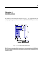
1
Chapter 1
Introduction
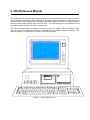
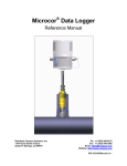
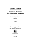
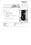
The Model CK4 CORROSOMETER instrument is designed to read CORROSOMETER and
CORROTEMP probes, and to simplify both probe reading and data presentation. CORROTEMP
probes incorporate temperature measurement into the standard CORROSOMETER probes, without
any additional connections.
Figure 1.1 CK4 CORROSOMETER Instrument
The CK4 joins a new generation of multi-parameter corrosion monitors, including the CORRDATA
Mate II, designed to read both metal loss and temperature. This portable unit has a built-in memory
which stores readings for later retrieval, so that operators do not have to carry a notebook and pencil
for manual recording.
2 CK4 Reference Manual
The combination of corrosion and temperature measurement is particularly useful in process plants,
chemical plants and refineries, where changes in operating temperature can have a major impact on
corrosion rates. High temperatures that push or exceed the design conditions may improve output,
but may result in unacceptably high corrosion rates. The CK4 brings direct correlation between
temperature and corrosion rate from one instrument.
The CK4 instrument allows readings to be stored for up to 26 probes. This stored data is later
retrieved on the CK4 and entered into the CORRDATA CK Graphical Software package. This
software package is supplied free of charge with each instrument.
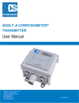
Figure 1.2 Data display on P.C.
Graphical displays of metal loss against time, and temperature against time are immediately available
for analysis and print-out. Cursors allow selection of any portion of the graphs for automatic
statistical computation of corrosion rates, or average temperature on CORROTEMP probes. 1,131
probe readings on each probe can be displayed, and zooming in can be done to as little as one day.
MS DOS graphics enables any screen to be printed at the touch of a button.
4 CK4 Reference Manual
5
Chapter 2
Specification
CK4 CORROSOMETER Instrument
Electronics
Ë
Compatible with all CORROSOMETER and CORROTEMP probes
Ë
LCD Readout
Ë
Sealed membrane keyboard
Ë
Metal loss resolution - 0.1% of probe span
Ë
Metal loss repeatability
- ± 0.5% of probe span
Ë
Temperature resolution
- 10 C
Ë
Temperature accuracy
- ± 30 C including probe sensor
Ë
Power Supply
- 6 AA Alkaline cells
Ë
Battery Life
- Typical 8 hours of continuous operation
Ë
Automatic power shut off in 45 secs after reading or non-use
Ë
Supplied with test probe
Ë
Reading memory for 26 probes
6 CK4 Reference Manual
Mechanical
Ë
Splash-proof enclosure
Ë
Dimensions 7.75"H x 4.30"W x 2"D ( 196.8 mm x 109.2 mm x 50.8 mm )
Ë
Supplied in carrying case
Ë
Weight without carrying case 1.5 lb. ( 680 g )
Ë
Weight with carrying case 5.5 lb. ( 2.5 Kg )
Environmental
Ë
Temperature range:
Operating
Storage
Ë
Humidity
-
0oF to 122oF ( -18oC to 50oC )
0oF to 150oF ( -18oC to 70oC )
0 - 95% ( non-condensing )
P.C. Requirements
Ë
IBM P.C. or compatible
Ë
VGA or EGA graphics
Ë
640k memory
Ë
1 floppy disk drive
Ë
Hard disk (Memory requirement: 400K plus 40K per probe)
Ë
MS DOS 3.3 or higher operating system ( MS DOS 4.01 or 5.0 preferred)
7
Chapter 3
Installation
NOTE: Your CK4 instrument was carefully tested, inspected and
packaged prior to shipment. Before unpacking the instruments,
please inspect the packaged materials for shipping damage and
retain damaged packaged materials to support any claim against
your freight carrier should this become necessary.
Unpacking
Carefully remove the instruments from their packages. Included in the package you should
find:
CORROSOMETER CK4 Instrument
Ë
Ë
Ë
Ë
Ë
Hand held CORROSOMETER CK4 instrument.
Instrument carrying case.
CK4 and CORRDATA CK Software
Quickstart and Reference Manuals.
CORRDATA CK Software Diskettes.
CORROSOMETER/CORROTEMP test probe.
Intrinsic Safety
The probes, and CK4 instrument have intrinsic safety ratings for use in electrical hazardous
area environments. Applicable certifications are identified on the System components
according to units ordered.
The intrinsically
safe system has been certified with a rating of EEx ia IIC T4 at temperatures
of up to 500C. For temperatures from 500C to 700C the rating is EEx ia IIC T3. This means
that the system is safe for use in the severest of electrical hazardous areas, where explosive
gases are always present (Zones 0, 1, and 2; Divisions 1 and 2, all groups) even with up to
two fault conditions (designated by ia).
The gas classification IIC is the most stringent including gases such as acetylene and
hydrogen. This part of the rating relates to the spark energy that is required to create an
explosion.
Gases have a separate classification for explosive tendency based on hot surface temperatures
which are not necessarily the same as the spark ignition energy. The temperature rating T4
indicates that no temperature of the equipment exceeds 1350C at 500C even under fault
8 CK4 Reference Manual
conditions. This rating includes all listed gases except carbon disulphide (which requires T5
rating)
Care must be taken with intrinsically safe systems to maintain their carefully designed
integrity. The major features to note are as follows:
1.
The batteries in the CK4 instrument must be replaced in a safe area even if
the unit is intrinsically safe, since the standard alkaline batteries are only safe
if housed in a suitable enclosure.
2.
Absolutely no substitution of parts or unauthorized repairs must be
undertaken or the certifications are rendered invalid.
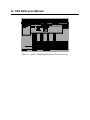
CORROSOMETER CK4 Instrument
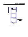
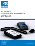
The CK4 is supplied with a set of six 1.5 V AA alkaline batteries. To install these batteries
remove the access panel on the back of the unit (see Figure 3.3) and install the batteries with
the polarities as indicated.
Chapter 3 Installation 9
Figure 3.1 Battery Replacement on CK4
10 CK4 Reference Manual
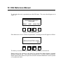
To check that the unit is operational press the ON button. The screen should appear as in
Figure 3.4.
ROHRBACK COSASCO
SYSTEMS
READ
DISP
SPAN TIME
>
>
>
>
F1
F2
F3
F4
Figure 3.4 CK4 Start-Up Screen.
If the batteries are low or in need of replacement, a warning screen will appear as follows.
REPLACE BATTERY NOW!
EXIT
>
>
>
>
F1
F2
F3
F4
The battery is tested both at initial switch on, and during probe measurement.
Battery back up for memory in the Mate II is provided by lithium batteries mounted
internally within the unit. These batteries should provide 7-10 years of back up capacity.
Replacement of these batteries requires the unit to be returned to Rohrback Cosasco Systems
or an authorized dealer.
Chapter 3 Installation 11
CORRDATA CK Software
The minimum requirements for the P.C. are as follows:
Ë IBM P.C. or compatible.
Ë EGA/VGA graphics card.
Ë 640 K memory.
Ë One floppy disk drive.
Ë Hard disk.
Ë MS-DOS 3.3 or higher operating system (MS-DOS 4.01 or 5.0 preferred)
The CORRDATA CK Software package is included with the CK4 instrument. Both 3½ and
5¼ low density diskettes are supplied for maximum compatibility.
To install the CORRDATA CK Software, place the appropriate diskette in your floppy drive.
At the DOS prompt, change the drive to this floppy and type install. Follow the on-screen
instructions.
NOTE:
The install program also requests selection of
COM1 or COM 2 serial port. Although the serial port is not
used with manual input readings from the CK range of
portable instruments, this program is also capable of
operating with the CORRDATA Remote Data Collectors, and
Mate I or II probe reading and data transfer units. These
systems allow fully automated data collection and direct
transfer to the P.C. without the need for any manual data
transfer. For further details contact Rohrback Cosasco
Systems Inc.
The default directory is CORRDATA and is installed in the root directory of the C drive.
When the installation is complete, remove the CORRDATA CK Software diskette and save
as a backup. To commence the program select the CORRDATA directory and then type
"CK".
12 CK4 Reference Manual
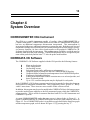
13
Chapter 4
System Overview
CORROSOMETER CK4 Instrument
The CK4 is a portable instrument capable of reading either CORROSOMETER or
CORROTEMP probes. CORROTEMP probes are the same as CORROSOMETER probes,
but have an additional temperature measurement incorporated. This measurement is
incorporated without any additional connectors or connectors pins. Both the metal loss and
temperature readings are recorded by the CK4 and the readings can be stored in up to twentysix memory locations, for later retrieval and transfer to the graphical CORRDATA CK
Software supplied with the instrument. This reading storage capability avoids the need to
manually write down the probe readings. CORROTEMP probes may be recognized by the
name on the probe body and the letter "T" after the probe model number.
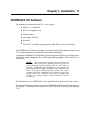
CORRDATA CK Software
The CORRDATA CK Software supplied with the CK4 provides the following features.
Ë
Ë
Ë
Ë
Ë
Ë
Ë
Ë
Ë
Menu style selection.
Probe configuration.
On-line help screens.
Selection of units (mils, millimeters or micrometers).
Graphical display of metal loss data for CORROSOMETER probes.
Graphical display of metal loss and temperature from CORROTEMP probes.
Zooming in on graphical displays.
Editing of metal loss data to show corrosion rates over selected periods, and
dates of selected period.
Up to 1131 corrosion data points may be displayed for each probe.
In the CORRDATA CK Software program provision has been made for future development
and extension of integrated corrosion data. This is apparent by some "grayed" or " barely
visible" menu items. These items are not accessible in this software release.
In addition, this program may be used as an add-in the CORRDATA Basic Software program
to provide manual input capability to the fully automated system which the CORRDATA
system provides. This is useful to customers that have both CK3 or CK4 instruments and
CORRDATA systems.
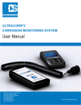
A typical CORROSOMETER probe data entry screen is shown below in Figure 4.1. A
typical CORROSOMETER or CORROTEMP probe metal loss graph output is shown in
Figure 4.2. For a CORROTEMP probe it is possible to toggle between the metal loss graph
and the temperature graph, such as shown in Figure 4.3, by pressing the key "T".
14 CK4 Reference Manual
Figure 4.1 Typical CORROSOMETER Probe Data Entry Screen
Chapter 4 System Overview 15
Figure 4.2 Typical CORROSOMETER or CORROTEMP Probe Metal Loss Graph
Figure 4.3 Typical CORROTEMP Probe Temperature Graph
16 CK4 Reference Manual
17
Chapter 5
System Configuration Procedures
Entering Probe Configuration information on the P.C.
CORROSOMETER and CORROTEMP probe configuration data is easily entered on the
P.C. with CORRDATA CK Software. This configuration is subsequently used for displaying
the manually entered probe readings in engineering units on graphical displays.
To commence probe configuration on the P.C., select the CORRDATA directory in which
the CORRDATA program is located and type CK to start the program. Press Enter to clear
the RCS CORRDATA CK introduction screen, and display the main menu. Help screen
information is available via the F1 key for the menu items.
Figure 5.1 Main Menu Screen
18 CK4 Reference Manual
From the main menu and sub-menu select SetUp, and Units. Select the engineering units
required for display purposes from mils (.001"), millimetres (mm), or micrometres (µm),
and press Enter.
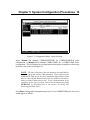
For first time probe configuration select Configure.
NOTE: Menu items may be selected using the cursor keys, space
bar, tab (forward), shift + tab (backward) keys and Enter, or by
typing the highlighted letter.
Figure 5.2 Configuration Mode - Probe List Summary.
For this first time configuration, or for new additions to the existing list, select NEW to
display the sub-menu of input selections.
Chapter 5 System Configuration Procedures 19
Figure 5.3 Configuration Mode - Input Selection.
Select Manual Co (Manual CORROSOMETER) for CORROSOMETER probe
configuration or Manual CoT (Manual CORROTEMP) for a CORROTEMP probe
configuration. This will display any existing entries on the probe list together with an entry
menu bar, such as the list in Figure 5.2.
NOTE: The other selections in this sub-menu are not applicable to
use of this program with the CK4 instrument. They are part of the
CORRDATA software for the fully automated data collection that
may be achieved with Remote Data Collectors (RDC's) and either a
Mate I or Mate II data transfer unit. To see a demonstration of the
capability of this type of system, retrieve the demonstration graph
DEMO.SAV as described later in the section "Archiving and
Retrieving Old Data Files".
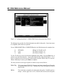
Press Enter to bring up the information entry screen. For a CORROTEMP probe, the screen
would appear as follows.
20 CK4 Reference Manual
Figure 5.4 Configuration Mode - CORROTEMP Probe Information Entry Screen.
The dialogue box provides for all the information needed for this probe. Some items must
be completed, while others are optional.
For an CORROSOMETER or CORROTEMP probe, the fields that must be completed are:
a)
b)
c)
ID Number
Type
Span
(Range 1 to 50 and A to Z)
(See Probe or Figure 5.5)
(See Probe or Figure 5.5)
Use the 8 or 9 keys to move between the highlighted entry fields. Press the Enter key to
gain access to the data entry box. Type in the required data, using the backspace, 6 or 7
arrows, or delete keys as necessary. For fields with pre-selected values use the 6 or 7 arrows.
When a field entry is correct, press Enter to complete.
The entry screens for each type of probe are similar except as noted below:
Probe Tag
This is an optional field of 12 character maximum, normally used for probe
tag numbers such as AE 3041. Alternatively, a brief description or location
may be used.
ID No.
This is the letter or number to be allocated to this probe. Each ID must be a
unique. A letter, upper case A to Z, is ideal as this can be used as the probe
Chapter 5 System Configuration Procedures 21
memory location on the CK4. Numbers between 1 and 50 may also be used.
This is the primary means of identifying each probe.
Location
This is an informational field only which allows additional identification
information up to 30 characters in addition to the tag number field.
Model
Number
This is a convenient field to store the probe identification information
which can be useful for reordering purposes. Example: 3500-T10-K0300518-0-0-0.
Alloy
This is the field for identification of the probe element alloy for
CORROSOMETER and CORROTEMP probes. Typically the UNS alloy
code is used such as K03005 for pipe grade carbon steel. Alternatively
Carbon Steel, 304 SS, or Monel 400, or similar may be used if within the 8
character maximum.
Type
For CORROSOMETER and CORROTEMP probes this is the probe type
identified on the probe and detailed in Figure 5.5.
Span
This is identified on the probe and entered in mils even if millimetres or
micrometres display units are selected. The mils range is the only figure listed
on the probe for reasons of space.
Alarm
Rate
This is provided for informational purposes only. Since the corrosion
data is historical, active current alarms in the normal sense are not applicable.
Once all the necessary information has been completed on this screen and is correct, press
F2 to save the information. This will then return to the configuration mode - input selection
Figure 5.3.
Repeat the procedure with the next probe entry until all the necessary entries have been
completed. When the final entry has been saved, use the Esc key as necessary to move back
up the menu tree.
To edit any of the entries, select Configure from the main menu to display the existing probe
list summary. Use the arrow keys to move the highlight bar to the required probe. Select
Edit from the menu bar. The information entry screen will appear which may then be edited
as required and saved with the F2 key. If you wish to exit without making any changes use
the Esc key.
22 CK4 Reference Manual
WARNING! Editing is primarily for use at initial configuration.
Changing probe type, span, after data has been collected may
distort the data.
To delete an entry select Configure from the main menu to display the probe list. Select the
required entry with the highlight bar, and select Delete from the menu bar.
Once all the configuration information has been loaded into the P.C., the program is ready
to receive the first set of probe data.
Setting the Clock on the CK4
The CK4 has its own clock so that individual probe readings are automatically date and time
stamped. To set the CK4 clock, switch ON the CK4, which will display the following
screen.
ROHRBACK COSASCO
SYSTEMS
READ
DISP
SPAN TIME
>
>
>
>
F1
F2
F3
F4
Press TIME (F4)
SET DATE Jan 30, 93
TIME 15:07:28
MONTH DAY
YEAR EXIT
>
>
>
>
F1
F2
F3
F4
To set the month, press MONTH (F1) once to increase. Hold down the key to scroll through
the months. To reverse the direction of scrolling, press the ALPHA /NUMERIC key once.
To toggle back the scrolling direction,press the ALPHA/NUMERIC key again. Follow the
Chapter 5 System Configuration Procedures 23
same procedure to change the DAY (F2), and the YEAR(F3). When complete press EXIT
(F4). This will change the screen to the following.
DATE Jan 30, 93
SET TIME 15:07:28
HOUR
MIN
SEC
EXIT
>
>
>
>
F1
F2
F3
F4
To set the hour, press HOUR (F1) once to increase. Hold down the key to scroll through the
hours. To reverse the direction of scrolling, press the ALPHA /NUMERIC key once. Press
the ALPHA/NUMERIC key to return to forward scrolling again.
WARNING! The hour is set on the military 24 hour clock, where
00:00 hours is midnight at the start of the day, and 12:00 is midday.
Follow the same procedure to change the MIN (F2), and the SEC (F3). When complete
press EXIT (F4) to return to the main menu.
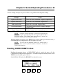
Configuration of CK4 Probe Span
Corrosion rate data is best reviewed and analyzed in graphical form on the P.C. where the
trend through many points is possible.
The highest resolution of historical corrosion data is
NOTE:
obtained with a CORRDATA system using Remote Data Collectors
(RDC's) which record probe readings at regular intervals from every
5 minutes to every 24 hours. This provides enhanced detection of
corrosion upsets.
Input of probe span is only necessary if an approximate corrosion rate calculation is required
on the CK4 at the time of reading. This corrosion rate is then based on the current and last
probe reading only. If this calculation is not required on the CK4, this section of the
configuration may be omitted.
24 CK4 Reference Manual
First switch ON the CK4.
ROHRBACK COSASCO
SYSTEMS
READ
DISP
SPAN TIME
>
>
>
>
F1
F2
F3
F4
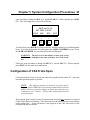
Press SPAN (F3).
SET SPAN MODE
SELECT LABEL (A-Z)
EXIT
>
>
>
>
F1
F2
F3
F4
Press the key (A-Z) corresponding to the probe label to be configured. Normally, the probes
on the system will have been labelled with letters A up to as high as Z. Using the same
identification on the CK4 for the probes will keep identification simpler and avoid confusion.
The following screen will be displayed.
SET SPAN >10<
TENS
ONES
EXIT
>
>
>
>
F1
F2
F3
F4
Press the TENS (F1) key to increase the tens value, and press the ONES (F2) key to increase
the units value of the probe span. Hold down the key to scroll up through the values. To
reverse the direction of scrolling, press the ALPHA/NUMERIC key once before using the
TENS or ONES keys; press the ALPHA/NUMERIC key again to toggle back to the normal
Chapter 5 System Configuration Procedures 25
scrolling. Enter the probe span in mils as marked on the probe, irrespective of the units
chosen in the SetUp of the P.C. program. The probe spans for various probe types are also
listed in Figure 5.5
NOTE:
A corrosion rate will only be computed on the CK4
instrument display if the probe readings are more than fourteen days
apart.
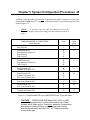
CORROSOMETER or CORROTEMP
Probe Element
Type
Span
(mils)
Strip Loop S4
C
1
Flush Element S4
Atmospheric Element S4
Strip Loop S8
Tube Loop T4
B
D
C
B
2
Flush Element S8
Atmospheric Element S8
Tube Loop T8
B
D
B
4
Flush Element S10
Cylindrical Element T10
B
D
5
Flush Element S20
Cylindrical Element T20
Wire Loop Element W40
B
D
A
10
Wire Loop Element W45
A
11.25
Flush Element S20
Wire Loop Element W80
B
A
20
Cylindrical Element T50
D
25
Figure 5.5 CORROSOMETER and CORROTEMP Probe Types and Spans
CAUTION: CORROSOMETER Model 2500, 3500, or 4500
probes are designated as a "cylindrical" element, not a "tube"
element which refers only to "tube loop" elements. If tube/strip or
wire element is selected but a cyclindrical element is being
read the measurement will return as "-90". Please select the
correct probe type.
26 CK4 Reference Manual
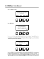
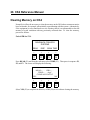
Clearing Memory on CK4
Normally it will not be necessary to clear the memory on the CK4 unless extraneous entries
have been made, for example, when initially experimenting with the system. Alternatively,
if the equipment is to be transferred to a new location, then it is recommended to clear the
memory to avoid confusion with any previously collected data. To clear the memory,
proceed as follows.
Switch ON the CK4.
ROHRBACK COSASCO
SYSTEMS
READ
DISP
SPAN TIME
>
>
>
>
F1
F2
F3
F4
Press READ (F1),and from the sub-menu select WIRE (F1). Then press in sequence F1,
F2, and F3. The screen will display the following.
MEAS =. . . . CHK =. . .
TEMP =. . . . degC
CLEAR ALL DATA??
YES
NO
>
>
>
>
F1
F2
F3
F4
Select YES (F1) to complete the deletion, or NO (F4) to exit without clearing the memory.
27
Chapter 6
Normal Operating Procedures
Once the probe configuration has been entered on the P.C., the ID designation letters should be noted
and the probes marked accordingly on the probes. This reduces the possibility of entering the probe
reading in an incorrect memory location.
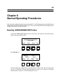
Reading CORROSOMETER Probes
At the first CORROSOMETER probe to be read, remove the connector cap from the probe,
plug in and switch ON the CK4.
ROHRBACK COSASCO
SYSTEMS
READ
DISP
SPAN TIME
>
>
>
>
F1
F2
F3
F4
Press READ (F1).
MEAS = . . . CHK = . . .
TEMP = . . . . deg C
WIRE
T/S
SPEC
TEMP
>
>
>
>
F1
F2
F3
F4
Select the probe type with the F keys, or with the keys A, B, C, or D. Wire element probes
are type A; Tube/Strip (T/S) loop and flush probes are type B or C; Special or cylindrical
element probes are type D. This will display the screen.
28 CK4 Reference Manual
MEAS = . . . CHK = . . .
TEMP = . . . . deg C
SELECT LABEL (A-Z)
EXIT
>
>
>
>
F1
F2
F3
F4
Select and press the key (A-Z) corresponding to the probe identification. The CK4 will then
take approximately 2 minutes and 45 seconds to read the probe. The CK4 will indicate that
a reading is in process, and when complete will indicate readings such as the following.
MEAS = 100 CHK = 805
TEMP = . . . . deg C
EXIT
>
>
>
>
F1
F2
F3
F4
NOTE: Corrosion "measure" and "check" readings are displayed
in units of " divisions". 0 to 1,000 divisions represents 0 to 100% of
the useful probe life, or probe span. One division is 0.1% of the
probe span. These units are converted to engineering units
automatically from the probe configuration information entered in
the CORRDATA CK software program.
Chapter 6 Normal Operating Procedures 29
Various warning messages may occur if there is any problem with the probe reading.
Message
Action
Replace Probe Soon!
Probe life is 80% consumed. Prepare a replacement
Replace Probe Now!
Probe life is 95% consumed. Replace now.
Probe at end of Life
Probe life is exceeded. Replace Probe
Check Reading Bad!
The internal probe reference element is damaged.
Replace probe.
Replace Batteries
Replace batteries in an electrically safe area
NOTE: A shorter reading time may be achieved by pressing the
SPACE key before selecting the probe letter against which to store
the probe reading. This reading takes approximately 1 minute, but
will not be as accurate as the normal reading.
When the reading is complete, press EXIT (F4) to return to probe type selection screen, or
switch OFF the CK4 and proceed to the next probe to be read.
NOTE: The CK4 has an automatic shut-off 45 seconds after a
probe has been read or if the instrument is inactive, in order to
conserve the batteries.
Reading CORROTEMP Probes
Reading the corrosion data on a CORROTEMP probe is exactly the same as for the
CORROSOMETER probes described above. To read the temperature on these probes, select
TEMP instead of probe type as follows.
Switch ON the CK4 and select READ (F1) to show this screen.
MEAS = . . . CHK = . . .
TEMP = . . . . deg C
SELECT PROBE TYPE
WIRE
T/S
SPEC TEMP
>
>
>
>
F1
F2
F3
F4
30 CK4 Reference Manual
Press TEMP (F4). The instrument will indicate that the probe temperature is being read.
After approximately 45 seconds the probe temperature reading will be displayed along with
the measure and check probe readings if these have already been taken on this probe.
WARNING! For CORROTEMP probes, remember to read both
the corrosion and the temperature data.
NOTE: Actual date and time display is linked to the corrosion data,
since there is limited display space to show it separately for both
temperature and corrosion data. This is not a problem if both
corrosion and temperature readings are taken at the same time, as
recommended. However it would have an effect if the corrosion and
temperature were taken at significantly different times on a particular
probe.
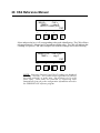
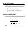
Displaying Probe Data on the CK4
Probe data may be reviewed on the CK4 at any time, either in the field or at the P.C. for
transfer to the CORRDATA CK Software package. To display the data, switch ON the CK4
instrument, and press DISP (F2).
MEAS = . . . CHK = . . .
TEMP = . . . . deg C
SELECT LABEL (A-Z)
EXIT
>
>
>
>
F1
F2
F3
F4
Press the key (A-Z) for the probe to be reviewed. This will show a display similar to the
following.
Chapter 6 Normal Operating Procedures 31
MEAS = 105 CHK = 802
TEMP = +25.6 deg C
RATE = 5.2 MPY
Feb 02,93 16:28
EXIT
>
>
>
>
F1
F2
F3
F4
NOTE:
The corrosion rate on the third line of the display is
computed on the metal loss from the previous reading only. The
value will only be displayed if the readings are at least 14 days apart.
No negative rates will be displayed, if for some unusual reason the
reading decreased from the previous one. Rates will also not be
computed for data points more than 365 days apart.
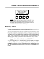
Replacing Probes
Warnings of impending probe replacement is given both on the CK4 instrument at the time
of reading, and on the CORRDATA CK software probe summary list.
If the probe being replaced is of the same type, the reading on the CK4 instrument is carried
out as normal once the probe has been replaced. On the P.C., the previous probe data should
be archived as described later in this chapter, and the probe configuration deleted from the
Configure menu. The probe should then be reconfigured as a New probe with the same ID.
This process clears the old readings from the current probe list and re-initializes the new
"check" reading. This first "check" reading becomes the reference against which the
subsequent "check' readings are compared for checking the reference element integrity.
NOTE: A bad "check" reading causes the subsequent graphical
displays to have a thin line instead of the normal thick line.
If the probe being replaced is of a different span, the probe span on the CK4 should be
changed accordingly. If the probe is of a different type make sure that the correct type is
entered on the CK4 at the time of reading. On the P.C., archive the old probe data as
described later in this chapter, delete the old probe data by deleting the probe from the
Configure menu. Enter the new probe configuration information, and then the new probe
data. The first probe data entered then becomes the reference for the subsequent "check"
readings.
32 CK4 Reference Manual
Entering Probe Data into the P.C.
When all the probe data has been collected on the CK4, it is time to transfer the data to the
CORRDATA CK software program. The CORRDATA program provides immediate
graphing of the probe data, automatic corrosion rate calculation of any selected data, printing
of the graphs, and archiving of the data for future reference.
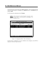
To commence probe data entry, start the CORRDATA CK program, and from the main menu
select File, and from the sub-menu Man Input. This will display the listing of configured
probes.
Figure 6.1 Manual Input Probe List
NOTE: If this program is used as an add-in to the CORRDATA
program for Mate I or Mate II to permit additional input from a CK3
or CK4 instrument, this list will only display probes that have been
configured for manual input. This simplifies selection of manual
entry probes, and avoids confusion with fully automated data entries.
Use the 8 and 9 keys to select the probe for which data is to be input, and press the Enter
key. This will bring up the probe data input screen.
Chapter 6 Normal Operating Procedures 33
Figure 6.2 CORROSOMETER Probe Data Input Screen
Switch ON the CK4 and press DISP (F2), and select the probe label corresponding to probe
selected on the P.C.
MEAS = 105 CHK = 802
TEMP = +25.6 deg C
RATE = 5.2 MPY
Feb 02,93 16:28
EXIT
>
>
>
>
F1
F2
F3
F4
On the P.C. the input fields for a CORROSOMETER probe are Date, Time, Check reading,
and Measure reading. On a CORROTEMP probe an additional data entry box for
temperature will also appear. Use the 8 and 9 keys to select the required field, and the Enter
key to enter and leave each data entry box. At initial entry the cursor is set to the overwrite
mode as indicated by the thick cursor.
In the Date field enter the month, day, year from the CK4 screen in the numerical format
indicated on the P.C. screen, including the / key between the month, day and year numbers.
When complete press Enter again to leave that data entry box.
For the Time field, enter the time as indicated on the CK4 screen. This format is the 24 hour
military format where 00:00 is midnight at the start of the day.
34 CK4 Reference Manual
NOTE: The Time entry box is set to a default of 12:00 mid-day.
This may be left unchanged if the time of day that readings were
taken is not critical. For example, some pipeline probe application
may show low corrosion rates of a mil per year or similar. In this
case, the variation of a few hours in the exact time that the probe is
read has negligible effect.
Enter the probe Check reading from the CK4 screen. The very first probe entry is the most
critical as it is the one against which all the others will be compared, to determine if the
check reading has gone bad. This is based on ± 20 divisions ( or ±2.5% of span) from the
initial reading, and is indicated by a thinner graph line than the normal for the segment of the
graph following the bad check reading.
WARNING! Once the first reading has been saved with the F2
key the initial check reading cannot be reset without first deleting
the probe in the Configure menu. This applies even if the Edit
command is used to change the check reading as displayed.
Enter the probe Measure reading from the CK4 screen. For a CORROSOMETER probe this
will complete the list of probe entries.
For a CORROTEMP probe, the last entry is Temperature. Enter the Temperature reading
from the CK4 screen in the same units of degrees centigrade. When satisfied with all the
entries for that probe reading press F2 to save the data.
NOTE: At least two probe readings must be entered to be able to
display a graph.
From the manual probe list summary, or the individual probe data list, the graphical display
may be viewed by the shortcut key F3. Esc will then return back to the same place. The full
display features are available under Display on the main menu.
When one probe entry has been completed, press Esc to return to the manual probe summary
list, and select the next probe for data entry. When all the probes have been completed press
Esc as required to return to the main menu.
Probe data entries may be edited in the probe data entry screen within certain limits. First
select the probe to be edited from the manual probe summary list, using the Insert key
instead of the Enter key.
The date of a probe reading in the middle of a list may only be changed between the dates
of the readings on either side of it. If the date is changed beyond this, the graph will "turn
back" on itself when viewed.
NOTE: The first and last probe readings in the list may not be
deleted from this screen. If this is required, the whole probe must be
deleted from the Configure menu.
Chapter 6 Normal Operating Procedures 35
The first reading in the probe data is particularly important as it is used by the program as a
the reference for the probe "check" against which all other "check" readings will be
compared to indicate a bad reference element. Once this reading has been entered initially,
even editing will not change the stored "check" reading even though it the reading on the data
entry screen can be changed. If this initial reading is incorrect, delete the probe in the
Configure mode and re-enter the data.
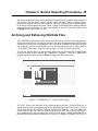
Archiving and Retrieving Old Data Files
The CORRDATA software provides for saving of files one at a time for archiving purposes,
and for retrieving files for viewing one at a time. Any files saved are automatically given the
extension .SAV to avoid overwriting the .DAT files if the CORRDATA directory is used.
For archiving, sub-directories should be set up for the appropriate time periods (such as
CD_MAR93) of the data. Each file can store up to 1131 sets of probe data points.
To save the current data to a sub-directory, first create the sub-directory in DOS at the
required location before entering the CORRDATA program. Start the CORRDATA
program and select Save, and press Enter to display the following screen.
Figure 6.3 CORRDATA P.C. Software File Saving
The .DAT files are the data files in the current program directory. Press the Tab key to
switch from the cursor in the pathname box to a highlight bar in the file list below. Use the
8 or 9 keys to make the required selection, and press the Tab key. This will display the
selected file into the "Save to" box with the cursor and a .SAV file extension, and leave a
gray highlight bar at the selected probe in the file box above. Modify the pathname as
necessary for the destination sub-directory (such as c:\CORRDATA\MAR 93\ID_B.SAV)
36 CK4 Reference Manual
already created in DOS. Press Enter to save the file, or use Esc to leave this screen without
saving.
NOTE: In the CORRDATA software, data files can only be saved
to an archive directory one at a time.
Archived data files may also be retrieved for the full viewing and analysis capability of the
CORRDATA program via the Display menu. Only one data file at a time may be viewed
from the archive files. Exiting the View or Range on the Display sub-menu to List or back
to the main menu will automatically cancel the archived data file selection. However range
zooming and rate calculations on graphs are fully operational on the retrieved file before
exiting as described.
NOTE: A retrieved file is never added to the probe list in the
current CORRDATA program directory. This may only be achieved
by changing the filename outside the program to an unused ID
number, installing the file in the CORRDATA program directory, and
then selecting this ID number through the NEW entry screen in the
Configure mode, and View in the display mode.
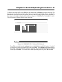
Chapter 6 Normal Operating Procedures 37
To Retrieve an archived file, select File from the main menu, and Retrieve from the sub-menu. The
box that appears will show a pathname box with a cursor present, and a blank file box. Modify the
pathname as required to select the required directory and files using wildcards and extensions as
convenient to simplify the displayed list of files (example: C:\CORRDATA\CD_MAR93\*.SAV).
This will produce a display similar to the following.
Figure 6.4 CORRDATA P.C. Software File Retrieval
Press Tab to switch from the pathname box to a highlight bar in the file list box. Use the 8
or 9 arrows to select the required RDC and press Enter. Press Display and View to display
the graph. The graph may be zoomed as required, and corrosion rates displayed with the
cursor keys and Enter. To return to the current operating probe list, press Esc and List.
38 CK4 Reference Manual
39
Chapter 7
Corrosion Data Analysis
In the CORRDATA software package the corrosion data may be viewed one probe at a time in a
graphical format which is generally the most useful to interpret corrosion events and trends.
Once data has been collected by the CK4 and transferred to the P.C., the CORRDATA software
program is ready to display that data.
It should be made clear here that CORROSOMETER and CORROTEMP probes directly measure
metal loss rather than corrosion rate. A single reading from a CORROSOMETER or
CORROTEMP probe cannot give the corrosion rate at that time. The metal loss over some finite
period of time must be used to calculate corrosion rate.
In a sense the CORROSOMETER and CORROTEMP probe metal loss measurements can be
likened to an automobile odometer or mileometer. The corrosion rate, on the other hand, can be
likened to the speedometer.
For a CORROSOMETER or CORROTEMP probe, the "current corrosion rate" must actually be
calculated on the metal loss occurring over some finite period of time, normally ranging from a few
hours to a few days. Hence for the CORROSOMETER or CORROTEMP probe corrosion rate is
always a calculated number.
The CORRDATA system can be extended with Remote Data Collectors (RDC's) and either a
CORRDATA Mate I or Mate II to automatically collect corrosion data. The advantage of RDC's
is to provide much higher frequency of measurements and a much improved resolution of corrosion
dynamics. The graphical display of RDC generated data is similar to data generated by individual
probe readings, in that straight lines are drawn between the individual readings. The only difference
between the two types of data is that data points from direct probe measurements are identified with
small circles around each point.
NOTE: An example of the type of data from such an RDC system
may be viewed by retrieving the DEMO.SAV file through the file
retrieve sequence.
40 CK4 Reference Manual
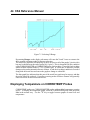
Displaying CORROSOMETER and CORROTEMP Metal
Loss Data
To display any of the current CORROSOMETER or CORROTEMP metal loss data, it is first
necessary to select the sub-directory containing the CORRDATA program and type the
command CK.
NOTE: Selection of the sub-directory CORRDATA and issuing of
the command CK may be incorporated into your PC shell or menu to
give direct entry to the CORRDATA program.
Select Display from the main menu and then List from the sub-menu to display the current
probe list. A probe list summary of all the probes on the system will be added to the screen.
Figure 7.1 Probe Display Selection
NOTE: Many of the selections in this menu are dimmed (or barely
visible). These additional features are for future developments in
integrated corrosion measurements.
Use the 8 or 9 keys to select the required CORROSOMETER or CORROTEMP probes.
Press Esc to return to the display sub-menu, and View to display a metal loss against time
graph such as the following.
Chapter 7 Corrosion Data Analysis 41
Figure 7.2 CORROSOMETER or CORROTEMP Probe Metal Loss Graph.
NOTE: If a probe has not been selected from the probe list or no
probe data has been collected for the selected probe, a blank graph
will briefly appear and then disappear when view is selected.
Initially the y-axis of the graph is scaled to the full span of the probe life e.g. a T10 probe has
a 5 mil span, a T20 has a 10 mil span (see Figure 5.5) and the x-axis has a time period
corresponding to the period of data collected, up to a maximum of 1,131 readings. The last
recorded probe data is on the right hand side of the screen.
Data older than the 1,131 points is discarded as new data is added. To keep data older than
this, save the data to a separate file as described in Chapter 6 "Archiving and Retrieving Old
Data Files".
On the X-axis the scale is identified in days. The date of the last recorded reading is shown
on the bottom of the graph (for example, on the above graph the last data was recorded on
8 Feb, 1993, where 8 Feb is from day 34.0 to 35.0. The first day is from 0.0 to 1.0). The
dates corresponding to the cursors may be displayed by pressing the Enter key at any time.
42 CK4 Reference Manual
Editing and Analyzing Metal Loss Graphs.
Select the required portion of the graph with the vertical cursors. To adjust the cursor for this
purpose, use the 6 or 7 arrow keys to move the cursor, and the Space bar to switch between
the two cursors.
NOTE: Initially the cursor lines are on the sides of the graph and
may not be readily visible. The selected cursor at entry to the screen
is the left hand line.
Once the desired selection has been made press Enter. The corrosion rate will be calculated
and displayed at the bottom of the screen along with the start and finish dates corresponding
to the cursors. The corrosion rate is determined by the statistical method of Linear
Regression (i.e. the slope of the best straight line through the selected data)
WARNING! No corrosion rate is displayed in this box until one
or other of the cursor lines has been moved, and the Enter key
pressed.
Figure 7.3 Metal Loss Graph with Rate Display
Chapter 7 Corrosion Data Analysis 43
To zoom in on the corrosion data graph press Esc to return to the display sub-menu and select
Ranges. Choose either the X-Select or Y-Select as required. If the Y-Select is chosen the graph
will reappear with two horizontal cursors lines at the top and bottom of the graph.
Use the 8 or 9 keys to move the cursor lines, and the Space bar to toggle between the two
cursors as shown in Figure 7.4. When you are satisfied with the selection press Esc.
If you also wish to zoom in on the X-axis choose the X-Select. The graph will reappear with
the X range zoomed in. Use the 7 or 6 keys to move the cursor lines and the Space bar to
toggle between cursors, and to select the required range. Press Esc twice and View to
display the zoomed in graph.
Figure 7.4 Selecting Y-range
44 CK4 Reference Manual
Figure 7.5 Selecting X-Range
Re-entering Ranges on the display sub-menu will cause the X and Y axes to return to the
fully zoomed out ranges ready for the next selection.
The metal loss graph line will normally be thick for most or all of the graph (2 pixels wide)
but may be thinner near the end of probe life (1 pixel). This is determined by the condition
of the CORROSOMETER or CORROTEMP probe check reading. The probe check reading
should remain constant within ± 2.5% of probe span. If it does not, it indicates possible
damage to the probes internal reference element. A bad check reading condition is recorded
along with the metal loss and causes the graph to change to a thin line.
The thin graph line indicates that this part of the metal loss graph may be suspect, and that
the probe should be replaced. Corrosion occurring on the reference element will generally
cause a decrease in the recorded metal loss.
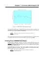
Displaying Temperature on CORROTEMP Probes
CORROTEMP probes are CORROSOMETER probes with an added temperature sensing
device. To display the temperature graph, select the CORROTEMP probe from the probe
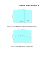
List in the normal way. Use the "T" key to toggle between graphs of metal loss and
temperature.
Chapter 7 Corrosion Data Analysis 45
Figure 7.6 CORROTEMP Probe temperature graph
The temperature graph may be zoomed in the same way as the metal loss graph. For
convenience, the X-axes of the two graphs zoom together to display the same time period of
data. The Y-axes of the two graphs are independent.
NOTE:
Only one graph of metal loss or temperature may be
zoomed in on at a time.
The average temperature measurement may be computed automatically over a period of time
by using the vertical cursors to select the desired time span and pressing Enter.
Printing from CORRDATA Software
To print from the CORRDATA software it is necessary to load an MS DOS graphics file
BEFORE loading the CORRDATA program, since there is no integral graphics printing in
the program. Recent MS DOS operating systems have screen graphics printing capability
from the Shift + Print Screen key.
For MS DOS 4.01, it is necessary to have typed "graphics" at the DOS prompt, before
running the CORRDATA software. This will be suitable for most dot matrix printers.
However it does not serve laser or inkjet printers.
NOTE: The graphics file may already be running if it is loaded as
part of your AUTOEXEC.BAT.
46 CK4 Reference Manual
Print screen is then initiated by Shift + Print Screen. Only a limited range of printers are
supported. See MS DOS manual "Graphics" for more detail.
With MS DOS 5.0 a larger range of printers are supported with the graphics command
including laser jet, paintjet, and deskjet printers.
For the common printers listed below type the command shown at the DOS prompt before
entering the CORRDATA program.
IBM Proprinter
HP Laserjet
HP Laserjet II
HP Deskjet
graphics/r
graphics laserjet/r
graphics laserjetii/r
graphics deskjet/r
The print screen is again initiated by Shift + Print Screen. For more detailed instructions
see the MS DOS 5.0 reference manual.
47
Chapter 8
Maintenance
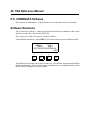
CK4 Instrument
The general requirements for maintenance on these units are battery change-out, general care
and cleanliness of the unit, and occasional inspection of the connectors for damage.
The CK4 operates from six AA battery cells. The use of alkaline batteries is recommended
which will give an average continuous operating time of 8 hours. The batteries are checked
under load conditions both when the unit is first switched on and during the probe
measurement sequence. If low batteries are detected the following screen will be displayed.
REPLACE BATTERY NOW!
EXIT
>
>
>
>
F1
F2
F3
F4
The CK4 has a small lithium battery back up on an internal circuit board with an anticipated
life of 7 - 10 years. The unit must be returned to Rohrback Cosasco or its authorized
representative for replacement of this battery.
48 CK4 Reference Manual
P.C. CORRDATA Software
This requires no maintenance. If any problems occur contact the factory for assistance.
Software Revisions
The revision level of the P.C. software can be checked from the part number on the system
diskettes, and the date of the main CK.EXE file.
The revision level of the CK4 may be checked as follows:
Switch ON the instrument. Select DISP (F2) from the start up screen, and then press F1.
MEAS =
CHK =
TEMP =
deg C
SOFTWARE REVISION 6.8
EXIT
>
>
>
>
F1
F2
F3
F4
The third line of the display shows the revision level. The software is programmed in ROM
(Read Only Memory). Any revisions require installation of a re-programmed chip, which
must be done by Rohrback Cosasco Systems.
49
Chapter 9
Troubleshooting
Checking CK4 Instrument
Trouble-shooting on the CK4 is very basic and simple. A test probe with specified measure,
check, and temperature readings is provided which may be read by the CK4. The readings
should be within the limits given on the test probe. If they are not then the unit should be
returned to Rohrback Cosasco Systems for repair. There are no user adjustments on the
instrument.
P.C. Software
If the CORRDATA program does not start up on your computer, check the specification of
your system meets the requirements listed in Chapter 2 of the manual.
If any part of the program does not work correctly, it may be the result of a corrupted
program file. If this occurs, re-install the CORRDATA program from the diskettes supplied.
This will not affect any probe data that has been collected, or the probe list file.
If Problems Still Occur
If problems still occur, contact the factory for assistance.
50 CORRDATA Mate II Reference Manual
51
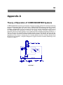
Appendix A
Theory of Operation of CORROSOMETER Systems
CORROSOMETER Systems are based on the electrical resistance method of corrosion monitoring
pioneered by Rohrback in the 1950's and 1960's. CORROSOMETER probes are basically "electrical
coupons." They determine the loss of metal from the probe by measuring the change in its
resistance. Because of the very low resistances involved, very sensitive monitoring circuits are used
in CORROSOMETER instruments to measure the change in probe resistance compared to a
protected reference element resistance series-connected to the corroding measurement element. A
"check" element is also included and is protected from the process along with the reference element.
The ratio of check to reference resistance should remain constant. If it doesn't, this indicates that
degradation of the reference element may be occurring and that metal loss readings obtained from
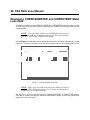
the probe are questionable. A simplified diagram of a typical electrical resistance monitoring circuit
is shown in Figure 1.
FIGURE 1
52 CK4 Reference Manual
As with coupons, CORROSOMETER probes must be allowed to corrode for a period of time before
accurate corrosion rate measurements can be made. The actual length of time required depends upon
the corrosion rate--the higher the rate, the shorter the time required, and vice-versa.
CORROSOMETER probes are available in a variety of styles and with useful probe life ("span")
ranging from 2-25 mils, in styles commonly used in process piping systems. Instrumentation to
measure electrical resistance probes divides the probe span into l000 "divisions." A probe with a 2
mil span is therefore theoretically capable of measuring thickness changes of 0.002 mils. In practice,
however, we recommend that a change in indicated metal loss of l0 divisions be required before the
data are used to calculate corrosion rate. Indications of an upward or downward trend can be
obtained with as little as a 4-division change, but care must be exercised in interpreting such small
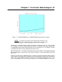
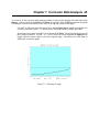
changes because other factors (e.g. temperature changes) can also be responsible. The actual time
required to produce meaningful corrosion rate information with common probe spans at different
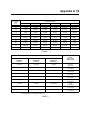
corrosion rates is shown in Figure 2 and summarized in Table 1.
FIGURE 2
Appendix A 53
Probe Span (mils)
Corrosion
Rate
(mpy)
2
4
5
10
20
25
0.1
73 days
5 months
6 months
12 months
24 months
30 months
0.5
15 days
29 days
37 days
73 days
5 months
6 months
1.0
7 days
15 days
18 days
36 days
73 days
3 months
5.0
35 hours
3 days
4 days
7 days
15 days
18 days
10
18 hours
35 hours
2 days
4 days
7 days
9 days
25
7 hours
14 hours
18 hours
35 hours
3 days
4 days
50
4 hours
7 hours
9 hours
18 hours
35 hours
2 days
75
140 mins
5 hours
6 hours
12 hours
23 hours
29 hours
100
105 mins
4 hours
5 hours
9 hours
18 hours
22 hours
TABLE 1
Elapsed Time* To:
Corrosion
Rate*
with 10 mil
Span Probe
Early Trend
Indication
(4 Div.)
Meaningful
Rate Data
(10 Div.)
End of Useful
Probe Life
(1000 Div.)
1.6 hours
4.0 hours
17 days
220 mpy
(5.6 mm/y)
4.0 hours
10.0 hours
1.4 months
88 mpy
(2.2 mm/y)
9.6 hours
1 day
3.3 months
37 mpy
(0.94 mm/y)
18.0 hours
1.8 days
6.0 months
20 mpy
(0.51 mm/y)
1.1 days
2.7 days
9.0 months
13 mpy
(0.33 mm/y)
1.5 days
3.7 days
12.0 months
10 mpy
(0.25 mm/y)
1.8 days
4.6 days
15.0 months
8 mpy
(0.20 mm/y)
2.2 days
5.5 days
18.0 months
6.7 mpy
(0.17 mm/y)
2.9 days
7.3 days
24.0 months
5 mpy
(0.13 mm/y)
* All data shown to two significant digits only.
TABLE 2
54 CK4 Reference Manual
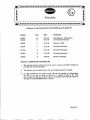
From Table 1, it would appear desirable to always choose probes with the lowest span available in
order to get the greatest sensitivity. However, the more sensitive the probe, the faster the entire
probe span will corrode away and require a new probe to be installed.
Table 2 illustrates this relationship.
It is our experience that the objectives of most monitoring programs can be achieved cost-efficiently
by selecting CORROSOMETER probes which will reach the end of their useful life in 6 - 9 months
at the expected corrosion rate. Unlike a monthly coupon replacement program, this electrical
resistance probe will continuously produce data that verifies that the average corrosion rate over the
previous 2-3 days is still at the originally-expected (design) rate. If the corrosion rate increases to
twice the design rate, meaningful data to permit the new rate to be calculated will be available in a
day and a half. Conversely, if the actual corrosion rate is below design, a longer period is required
before meaningful data are available to calculate the new rate.
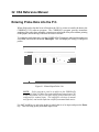
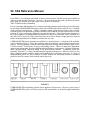
CORROSOMETER probe elements are available in a variety of styles. A selection of the available
styles is shown in Figure 3. Wire, tube, and strip-loop styles all have a loop of metal exposed to the
process. The loop protrudes from the end of the probe body through either a hermetic glass seal or
a Teflon/ceramic, Teflon/epoxy or epoxy seal/packing system. Choice of materials is dependent
upon stream composition, process conditions and performance requirements. Cylindrical elements
utilize specially-made, thin-wall tubing as the measurement element. Cylindrical probes are
generally "all-metal;" i.e., there is no other material exposed to the process. There are, however, also
some cylindrical probes available which join the probe body at a hermetic glass seal. A variety of
flush-mounted probes are also available; so-called because the measuring element is mounted
parallel to the flow stream, flush with the inside pipe wall.
FIGURE 3
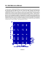
CORROSOMETER monitoring systems can be applied to all processes. However, some types of
CORROSOMETER probes are better suited to the requirements of particular applications than
others.
Appendix A 55
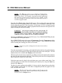
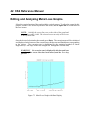
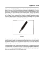
Different styles of CORROSOMETER probes are affected to different degrees by pitting attack.
Figure 4 shows the results of pitting attack on a wire loop probe. Although the remaining wire
thickness shows that only 30% or so of the probe span has been consumed, the probe is obviously
out of service. Cylindrical elements on the other hand, are affected to a much lesser degree by pitting
because of the much larger circumference of the measuring element. Wire loop and tube loop
elements also have a tendency to be electrically shorted by a bridge of iron sulfide corrosion product.
This is especially prevalent in low-velocity streams over an extended period. The effect of such
bridging is to reduce the measured metal loss of the probe, creating a misleadingly low corrosion
rate. Cylindrical probes demonstrate more resistance to iron-sulfide bridging due to their
construction and lower inherent resistance per unit length, thus minimizing the effect of the shunt
resistance. Where pitting or substantial FexSy deposition are expected to be problems, cylindrical
probes should be chosen wherever possible over loop-style probes.
FIGURE 4
Most cylindrical probes are of all-welded construction in order to eliminate the need for sealing
metal elements to non-metallic glass, epoxy or ceramic. This all-welded construction gives the probe
superior resistance to leaking. Probes with higher temperature ratings can also be constructed in the
all-welded style. A drawback to the all-welded style is that the element is electrically connected to
the pipe wall which can, in certain conditions, interfere with the corrosion reaction on the probe.
Also, because cylindrical probes are welded, in some conditions preferential corrosion can occur in
the heat-affected zones near the weld.
Flush probe elements are thin, flat metal sections embedded in epoxy or a hermetic glass seal inside
a metal probe body. Flush probes also experience certain characteristic problems, most notably:
lack of adhesion of the metal element to the epoxy, cracking of glass seals due to differential
expansion and erosion of the epoxy or glass due to high velocities, abrasive materials in the
flowstream or both. Flush CORROSOMETER probes mounted on the bottom of the line have been
shown to provide good results in a sour gas gathering system.
56 CK4 Reference Manual
Because the measurement element is part of the primary pressure seal, and because it's designed to
corrode, CORROSOMETER probes have a reduced resistance to leaking after prolonged exposure.
Once the measurement element has corroded through, the internals of the probe body are exposed
to the process fluid. Although materials are chosen in part for their strength and lack of permeability,
it is our experience that process fluids will permeate throughout the probe packing material. For this
reason, quality probes are constructed of corrosion-resistant body materials and include a secondary
pressure seal, often consisting of a hermetic glass-sealed connector. Other back-up seals are utilized
in special cases, especially where process fluids will attack glass (e.g. hydrofluoric acid service).
Please contact the factory if you have any questions about the compatibility of probe materials with
your application.
The reference and check elements are protected from the process to which the measurement element
is directly exposed. Temperature changes in the process will, therefore, affect the measure element
before the reference and check elements. Because of the very low resistances involved, these
changes can significantly affect the metal loss readings. CORROSOMETER probes incorporate
special design features to minimize the thermal resistance of the materials insulating the reference
and check elements from the process. It should also be noted that cylindrical probes are inherently
better able to react to temperature changes due to location of the reference and check elements
concentrically inside the measure element.
57
Appendix B
Special Conditions or Limitations for use of Intrinsically
Safe Equipment to European Harmonized Standards
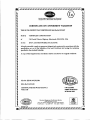
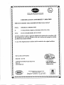
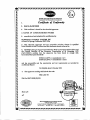
BASEEFA Certifications of the CORRDATA system to the harmonized European standard for
intrinsic safety are included in this Appendix.
a)
b)
BAS No Ex 92C2417
CORRDATA Mate, CORRDATA Mate II (14 pages)
BAS No EX 90C2388X Range of CORROSOMETER Probes (8 pages)
The conditions set out in these documents must be followed to ensure that the certifications are valid.
58 CK4 Reference Manual