1
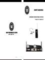
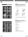
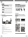
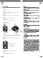
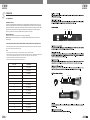
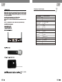
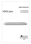
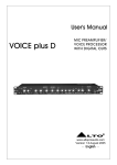
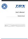
SEIKAKU TECHNICAL GROUP LIMITED
TOPP PRO
NF03124
/
TMW-9162R/T/M/P TOPP PRO_V1.0
TMW-9162R/T/M(PE03010)
0.18Kg/1
105g
A3
A4
A5
9
MAR.01.2008
PHFWA102-20080300001,A,1
17
PGBSC001-20071200093
WIRELESS MICROPHONE SYSTEM
TMW-9162 SERIES
TMW-9162
A
TMW-9162
AF
RF
Professional Wireless System
CH SEL
B
8 8
RF
ON
AF
UHF - PLL Synthesized Wireless
Dual Channel Multi-Freq Receiver
CH SEL
OFF
ANT-A
NF03124-1.0
MIN
MAX
AF LEVEL
AF LEVEL
MIN
MAX
POWER
ANT-B
TMW
TMW
SERIES
SERIES
SAFETY RELATED SYMBOLS
NOTE
Protective Ground
Before turning the unit ON, make sure that it is connected
to Ground. This is to prevent the risk of electric shock.
Never cut internal or external Ground wires. Likewise, never
remove Ground wiring from the Protective Ground Terminal.
This symbol, wherever used, alerts you to the
presence of un-insulated and dangerous voltages
within the product enclosure. These are voltages
that may be sufficient to constitute the risk of
electric shock or death.
This symbol, wherever used, alerts you to important
operating and maintenance instructions.
Operating Conditions
Always install in accordance with the manufacturer's
instructions.
To avoid the risk of electric shock and damage, do not
subject this product to any liquid/rain or moisture.
Please read.
Do not use this product when in close proximity to water.
Protective Ground Terminal
Do not install this product near any direct heat source.
Do not block areas of ventilation. Failure to do so could
result in fire.
Keep product away from naked flames.
AC mains (Alternating Current)
AC mains (Alternating Current)
Denotes the product is turned on.
Denotes the product is turned off.
WARNING
Describes precautions that should be observed to
prevent the possibility of death or injury to the user.
CAUTION
Describes precautions that should be observed to
prevent damage to the product.
Disposing of this product should not be placed in
municipal waste but rather in a separate collection.
WARNING
Power Supply
Ensure that the mains source voltage (AC outlet)
matches the voltage rating of the product. Failure to
do so could result in damage to the product and
possibly the user. Unplug the product before electrical
storms occur and when unused for long periods of time
to reduce the risk of electric shock or fire.
External Connection
Always use proper ready-made insulated mains
cabling (power cord). Failure to do so could result in
shock/death or fire. If in doubt, seek advice from a
registered electrician.
Do Not Remove Any Covers
Within the product are areas where high voltages may
present. To reduce the risk of electric shock do not
remove any covers unless the AC mains power cord is
removed. Covers should be removed by qualified service
personnel only.
No user serviceable parts inside.
Fuse
To prevent fire and damage to the product, use only
the recommended fuse type as indicated in this
manual. Do not short-circuit the fuse holder. Before
replacing the fuse, make sure that the product is OFF
and disconnected from the AC outlet.
IMPORTANT SAFETY INSTRUCTIONS
Read these instructions
Follow all instructions
Keep these instructions. Do not discard.
Heed all warnings.
Only use attachments / accessories specified by the
manufacturer.
Power Cord and Plug
Do not tamper with the power cord or plug. These are
designed for your safety.
Do not remove Ground connections!
If the plug does not fit your AC outlet seek advice
from a qualified electrician.
Protect the power cord and plug from any physical
stress to avoid risk of electric shock.
Do not place heavy objects on the power cord. This
could cause electric shock or fire.
Cleaning
When required, either blow off dust from the product
or use a dry cloth.
Do not use any solvents such as Benzol or Alcohol.
For safety, keep product clean and free from dust.
Servicing
Refer all servicing to qualified service personnel only.
Do not perform any servicing other than those instruct
-ions contained within the User's Manual.
Carts and stands - The
component should be used
only with a cart or stand
that is recommended by
the manufacturer.
A component and cart
combination should be
moved with care. Quick
stops, excessive force,
and uneven surfaces may
cause the component and
cart combination to overturn.
9
TMW
TMW
SERIES
SERIES
TABLE OF CONTENTS
1. INTRODUCTION.........................................................................................4
2. FEATURES.................................................................................................5
3. USEFUL DATA............................................................................................6
4. CONTROL ELEMENTS................................................................................6
5. OPERATION........... ...................................................................................9
6. CONNECTION DIAGRAM ...........................................................................11
7. TECHNICAL SPECIFICATION.....................................................................12
8. GUARANTEE.............................................................................................14
9. NOTE........................................................................................................15
TMW
TMW
SERIES
SERIES
INTRODUCTION
Thank you for choosing TOPP PRO.
Our Professional Audio Products are designed and tested by a highly qualified engineering team
with more than 20 years of experience. Great pride & care is placed in delivering products with
excellent performance, specifications and dependable reliability. Also great emphasis is placed in
creating and bringing to market products that can fill multiple applications and also offer customers
exceptional value.
Our creative and dedicated design & engineering team uses the latest tools in technology and the
latest concepts in acoustics design to create products for real-life applications. Every TOPP PRO
Audio product is tested and must comply to very strict Standards.
The TMW-9162 is the delicately designed UHF, PLL synthesized system. You can manually adjust
the channel of the transmitter to match that of the receiver if you know about the operating frequency
of it.
Generally, the TMW-9162 series consists of:
PLL UHF Non-Diversity Receiver
Handheld Transmitter
Body Pack Transmitter
PLL UHF NON-DIVERSITY RECEIVER
A
TMW-9162
AF
RF
Professional Wireless System
CH SEL
B
8 8
RF
ON
AF
UHF - PLL Synthesized Wireless
Dual Channel Multi-Freq Receiver
CH SEL
OFF
ANT-A
MIN
HANDHELD TRANSMITTER
BODY PACK TRANSMITTER
MAX
AF LEVEL
AF LEVEL
MIN
MAX
POWER
ANT-B
TMW-9162
TMW
TMW
SERIES
SERIES
INTRODUCTION
For the TMW-9162 series, there are several types of clip microphones are included in this product
range, please make sure that the proper microphone has been selected for your typical sound
reinforcement system before installation.
HM-38, Condenser Microphone
Preset impedance: 600 ohm;
Freq. response: 80-12 kHz;
Sensitivity: -68 dB+/-3 dB at 1 kHz;
Directional: Uni-directional;
Weight: 52 g (0.12Ib)
HM-58, Condenser Microphone
Preset impedance: 700 ohm;
Freq. response: 200-8 kHz;
Sensitivity: -65 dB at 1 kHz;
Directional: Uni-directional;
Weight: 54 g (0.12Ib)
Last but not the least, the operating frequency of this system may be varied from 798 MHz to 827 MHz, please
refer to your national EMC regulations to pick out the authorized frequency band (0 ~ F) for your end application.
FEATURES
PLL UHF NON-DIVERSITY RECEIVER
Pressing the flip switch to switch channel for desired Radio Frequency
LED indication RF
Two receiving modules
AF level displays
Two independent balanced outputs
Two independent squelch controls
Two independent volume controls
TRANSMITTER
Soft touch painting for comfortable use
Channel frequency adjusted manually
COMMON FEATURES
PLL synthesized design
Consistent operating frequencies to comply with the EMC regulations
16 channels frequency presets
Manufactured under ISO9000:2000, ISO/TS16949:2002 Quality Management System
TMW
TMW
SERIES
SERIES
+
-
+
+
Pin2 (+)
Tip
Sleeve
TS Type Unbalanced
Ring
Tip
Ring
Sleeve
(Linked to Pin1 manually,
)
Sleeve
Pin1 ( )
TRS Type Balanced
Pin2 (+)
Pin3 (-)
Pin3 (-)
Tip
XLR Type Unbalanced
TRS Type Unbalanced
Pin1 ( )
XLR Type Balanced
CONTROL ELEMENTS
4.1 PLL UHF NON-DIVERSITY RECEIVER
FRONT PANEL
(5)
SLEEVE RING TIP
3
2
1
3
2
A
AF
RF
Professional Wireless System
CH SEL
3
3
Tip
Ring
1
2
3
(1)
TIP RING SLEEVE
TMW-9162
1
2
2
(3) (4)
Tip
Ring
Sleeve
1
2
3
(6) (2)
Tip
Ring
Sleeve
1
1
(5)
TIP RING SLEEVE
Sleeve
B
8 8
RF
ON
AF
UHF - PLL Synthesized Wireless
Dual Channel Multi-Freq Receiver
CH SEL
OFF
ANT-A
MIN
MAX
AF LEVEL
AF LEVEL
MIN
MAX
POWER
ANT-B
1
3
2
Tip
Ring
Sleeve
TIP RING SLEEVE
(7)
Tip
1
3
2
2. RF Channel Indicators
These indicators show the selected channel whose range goes from 0 to F.
3. RF LEDs(CH A & CH B)
These LEDs light up when antennas receive signals.
Note: The receiver has two antennas. LED A lights up when antenna A receives more signals than
antenna B. LED B lights up when antenna B receives more signal than antenna A.
1
3
1
2
3
Tip
TIP SLEEVE
SLEEVE TIP
TIP RING SLEEVE
SLEEVE RINGTIP
Cent r e
Screen
Tip
Sleeve
Tip
Ring
Sleeve
Sleeve
Tip
Cent r e
Sleeve
Screen
Tip
Ring
Centre
Sleeve
Screen
TIP SLEEVE
2
2
3
3
1
1
5. Antennas
These antennas receive the signals from transmitter.
Sleeve
Tip
Ring
TIP RING SLEEVE
4. AF Level LEDs
When the receiver receives signal, the LED starts to light up. The higher the signal level is, the more
LEDs light up. When the signal level reaches peak, all LEDs light up. If there is no signal received, all
LEDs light off.
1
2
3
TIP SLEEVE
2
1. Power Switch
It switches your TMW-9162 ON and OFF.
Sleeve
1
2
3
1
2
3
1
2
3
TMW
TMW
SERIES
SERIES
CONTROL ELEMENTS
6. Channel Selectors
Press these flip switches slightly to switch channel for desired frequency.
7. Volume Controls
"AF LEVEL" are the potentiometers for volume controls.
REAR PANEL
(3)
(4)
(2)
(1)
1. DC Input
This DC jack is used to input 12-18 V 500 mA DC current.
2. Squelch Controls
These squelch controls are used to adjust the squelch levels. The adjustable squelch ranges are 95.0 dB~65.0 dB.
3. XLR Audio Outputs (Balanced)
These are two independent professional balanced XLR output connectors, A and B.
4. AF Output (Unbalanced)
This is a professional unbalanced output jack.
4.2 HANDHELD TRANSMITTER
(6)
(5)
(4)
(1)
TMW-9162
(2)
(3)
(7)
TMW-9162
1. Massive Front Grill
Extremely rugged spring steel mesh grill to protect the capsule underneath in tough stage or live performance.
2. Power Switch
Set the power switch in the position "ON", then the microphone is turned on and the BATT LED lights up.
TMW
TMW
SERIES
SERIES
CONTROL ELEMENTS
3. Power LED
When the unit is turned on, this LED lights up.
4. Band Selector
With an adjusting bar, the band selector can be used to switch to an expected frequency. Before switching
frequencies, turn off the microphone first and then turn on it.
5. Adjusting Bar
This adjusting bar is placed in the microphone. It is used to adjust squelch control and band selector for
switching frequencies.
6. Antenna
The antenna is integrated into the transmitter body for transmitting signals.
7. Battery Compartment
This unit may be powered from one pair dry or rechargeable batteries, size AA 1.5 V.
4.3 BODY PACK TRANSMITTER
(3) (6) (7)
(5)
(4)
TMW-9 162
(8)
(9)
(2) (1) (10)
1. Power Switch
Set the power switch in the position "ON", then the microphone is turned on and the BATT LED flashes once.
Set the power switch in the position" OFF", then the microphone is turned off and the BATT LED lights off slowly.
2. MINI 4P Connector
This connector is used to connect the unit with the clip microphones, for example, HM-38 or HM-58 condenser
microphones.
Pin1
Pin3
Pin 1 GND
Pin 2 Phantom power supply for condenser microphone
Pin 3 For guitar, bass and keyboards
Pin 4 For dynamic or condenser microphone
Pin2
Pin4
3. Battery Compartment
This unit may be powered from one pair dry or rechargeable batteries, size AA 1.5 V.
4. Belt Clip
It is the detachable belt clip for easy carry during the live applications.
TMW
TMW
SERIES
SERIES
CONTROL ELEMENTS
5.Antenna
It is the flexible antenna. To get effective transmission, never cover the antenna with hand, clothes, etc.
During the operation, and always position the transmitter nearby the receiver.
6. GT Level Switch
It is used to adjust the input signal level of electrical guitar. When an electrical guitar is being used it is
ineffective to adjust MT level switch.
7. MT Level Switch
It is used to adjust the input signal level of microphone. When an microphone is being used it is ineffective
to adjust GT level switch.
8. Band Selector
With the adjusting bar, the band selector can be used to switch to an expected frequency before switching
the frequencies, turn off the transmitter first and then turn on it.
(3) (6) (7)
(5)
9. Adjusting Bar
It is used to adjust BAND SELECTOR, MT SWITCH and GT SWITCH.
(4)
TMW-9 162
10. Power LED
When the unit is turned on, this LED flashes once. When the unit is turned off this LED lights off slowly.
When the batteries are short of power, this LED flashes. When the batteries can not be used, this LED
lights up.
(8)
(9)
(2) (1) (10)
OPERATION
5.1 PLL UHF NON- DIVERSITY RECEIVER
MANUALLY SELECTING FREQUENCY
Press this flip switch slightly to switch channel for desired frequency.
Pin1
OUTPUT VOLUME CONTROL
There are two independent master volume controls "AF LEVEL" on the front panel. They are used to
control the output volume. Turn the knob clockwise and the output volume increases. Turn the knob
counterclockwise and the output volume decreases.
Pin3
SQUELCH CONTROL
The job of a squelch circuit is to reduce audible noise. It eliminates noise during pauses in the audio
signal by muting the receiver every time and the audio level drops below a def ined th resho ld. The s quelc h
control on the receiver sets this threshold. Use the squelch control with care! If the squelch threshold
is too high, the squelch will not only cut out noise but mute quiet audio signals as well because the
squelch responds to the detected voltage and cannot distinguish between wanted signal and noise.
Besides that, a too high squelch threshold also decreases the usable range. The squelch range is
95.0 dB~65.0 dB. Use an adjusting bar to adjust the squelch selector for a right squelch threshold.
Pin2
Pin4
TMW
TMW
SERIES
SERIES
OPERATION
5.2 TRANSMITTER
FREQUENCY SELECT
In practice, to effectively avoid the interference from any lighting equipment, computers, fax machin es, etc n ear
by, it is usually advised to switch to another frequency to get best performance. The frequency range of this
system is UHF, 798 MHz ~ 827 MHz, and it is divided into 16 frequency bands according to the country's EMC
regulations; Each frequency band can be manually adjusted with an adjusting bar. If you want to switch a
frequency, you have to turn off the unit, adjust frequency and then turn it on again.
(3)
(4)
(2)
(1)
BATTERY REPLACING
Please be advised to use only one pair of AA 1.5 V batteries for power supply.
Caution: Danger of explosion if battery is incorrectly replaced. Replace the batteries only with the same or
equivalent type.
5.3 OPERATING FREQUENCY MATCHES BETWEEN THE RECEIVER AND THE TRANSMITTER
To make the operating frequency matched between the transmitter and the receiver, adjust the transmitter
and receiver manually for the same frequency.
Note:
1. If several systems are operated, do not use the same frequency at the same time.
2. If several wireless systems are used to avoid interference, ten frequencies can be selected simultaneously
at most. They are respectively CH 0, CH 1, CH 3, CH 4, CH 5, CH 6, CH 7, CH 8, CH 9,CH B.
3. The rest 6 frequencies are available for customer's choice.
Please refer to the following table to selectrequencies.
CH 0~CH F
FREQUENCY
0
798.125 MHz
1
798.325 MHz
2
798.925 MHz
3
799.325 MHz
4
800.725 MHz
5
802.725 MHz
6
805.725 MHz
7
807.925 MHz
8
811.525 MHz
9
815.725 MHz
A
820.825 MHz
B
822.725 MHz
C
823.225 MHz
D
824.625 MHz
E
825.425 MHz
F
826.625 MHz
(6)
(5)
(4)
(1)
(2)
(3)
(7)
TMW-9162
TMW
TMW
SERIES
SERIES
CONNECTION DIAGRAM
Either the 1/4" TRS phone jack or XLR connector can be wired in balanced and unbalanced modes, which
will be determined by the actual application status, please wire your system as the following wiring examples:
For 1/4" Phone jack
+
+
-
Tip
Ring
+
Tip
Ring
Sleeve
Sleeve
TS Type Unbalanced
Tip
Sleeve
TRS Type Balanced
TRS Type Unbalanced
For XLR connector
Pin2 (+)
Pin3 (-)
(Linked to Pin1 manually,
)
Pin1 ( )
(5)
(6) (2)
(3) (4)
Pin1 ( )
XLR Type Unbalanced
(5)
Pin2 (+)
Pin3 (-)
XLR Type Balanced
In-line Connection
(1)
For these applications the unit provides 1/4" TRS and XLR connectors to easily interface with most professional
audio devices. Follow the configuration examples below for your particular connection.
A
TMW-9162
AF
RF
Professional Wireless System
CH SEL
B
8 8
RF
Balanced
ON
AF
UHF - PLL Synthesized Wireless
Dual Channel Multi-Freq Receiver
CH SEL
OFF
MIN
MAX
AF LEVEL
AF LEVEL
MIN
MAX
POWER
ANT-B
TIP RING SLEEVE
SLEEVE RING TIP
3
3
1
1
2
2
1
3
2
TIP RING SLEEVE
Tip
Ring
Sleeve
Tip
Ring
Sleeve
1
2
1
2
3
3
Tip
Ring
1
2
3
Sleeve
Unbalanced
1
3
2
Tip
Ring
Sleeve
TIP RING SLEEVE
Tip
1
3
2
Sleeve
1
2
3
1
2
3
1
TIP SLEEVE
2
3
1
2
3
Tip
TIP SLEEVE
SLEEVE TIP
Sleeve
Tip
Ring
TIP RING SLEEVE
SLEEVE RINGTIP
Sleeve
Tip
Cente
r
Screen
Tip
Sleeve
Tip
Ring
Sleeve
Cente
r
Sleeve
Screen
Tip
Ring
Centre
Sleeve
Screen
TIP SLEEVE
TIP RING SLEEVE
1
1
3
3
(7)
2
2
ANT-A
1
2
3
1
2
3
TMW
TMW
SERIES
SERIES
TECHNICAL SPEACIFICAION
MODEL
SPECIFICATION
Channel
PLL UHF NON-DIVERSITY RECEIVER
Dual-channel
Receiver Type
Non-diversity
Oscillation Mode
Frequency Band
PLL UHF SYNTHESIZED
Frequency Response
Frequency Stability
UHF 798~827 MHz
50 Hz~50 kHz ( 3 dB)
0.005%
Audio Output
FM (F3E)
1%
100 dB
Unbalanced 6.3 mm phone jack 300 mV 15 kHz deviation
Balance Output
600 mV at
S/N Ratio
RF Sensitivity
Power Supply
Dimensions
90 dB
-100 dbm/30 dB SINAD
Weight
1.16 Kg (Approx.)
Modulation Mode
T.H.D
Dynamic Range
MODEL
SPECIFICATION
Oscillation Mode
Frequency Band
Frequency Response
Frequency Stability
T.H.D
Modulation Mode
RF Output Power
Dynamic Range
Tone Frequency
Current Drain
Max. Deviation
Battery
Microphone Capsule
4 Bands Choice
Dimensions
Weight
15 kHz deviation
DC 12 V~18 V/0.5 A
183(W)
430(L)
44(H)
BODY PACK TRANSMITTER
PLL UHF SYNTHESIZED
UHF 798~827 MHz
50 Hz~15 kHz ( 3 dB)
0.005%
0.8%
FM (F3E)
10 mW
100 dB
32.768 kHz
150 mA
35 kHz deviation
"AA" 1.5 V 2 pcs (battery life: more than 6 hours)
Condenser capsule
1. Ground
2. Condenser
3. Electric instrument
4. Dynamic
65(W) 111(L) 31(H)
0.105 Kg (Approx.)
TMW
TMW
SERIES
SERIES
TECHNICAL SPEACIFICAION
MODEL
SPECIFICATION
A
TMW-9162
AF
RF
Professional Wireless System
CH SEL
MIN
MAX
AF LEVEL
Oscillation Mode
PLL UHF SYNTHESIZED
Frequency Band
UHF 798~827 MHz
Frequency Response
50 Hz~15 kHz(
Frequency Stability
0.005%
T.H.D
0.8%
Modulation Mode
FM (F3E)
RF Output Power
10 mW
Dynamic Range
100 dB
Tone Frequency
32.768 kHz
3 dB)
Current Drain
150 mA
Max. Deviation
35 kHz deviation
Battery
"AA" 1.5 V
Microphone Capsule
Dynamic capsule
Dimensions
230 mm
Weight
0.16 kg (Approx.)
2 pcs (battery life: more than 6 hours)
B
8 8
RF
ON
AF
UHF - PLL Synthesized Wireless
Dual Channel Multi-Freq Receiver
CH SEL
OFF
ANT-A
HANDHELD TRANSMITTER
AF LEVEL
MIN
MAX
POWER
ANT-B
TMW-9162
TMW
SERIES
GUARANTEE
Topp Pro guarantees the normal operation of the product against any defect of manufacture
and/or vice of mater ial, by the term of (12) months, counted as of the date of purchase on the part
of the user, committing itself to repair or to change, to its election, without posi tion so me, any
piece or component that will fail in normal conditions of use within the mentioned period.
This guarantee is valid if the original buyer will have to present /display this certificate properly
sealed and signed by the selling house, accompanied by the corresponding invoice of purchase
where it consisted the model and serial number of the acquired equipment.
The guarantee does not cover:
-Damages caused by the illegal use of the product, repair and/or nonauthorized modification
conducted by people by Topp Pro.
-Damages caused by the connection of the equipment to other equipment different from the
specified ones in the manual of use, or by bad connection to these last ones.
-Damages caused by electrical storms, blows and / or incorrect transport.
-Damages caused by excesses or falls of tension in the network or by connection to networks
with a tension different from the required one by the unit.
-Damages caused by the presence of sand, acid of batteries, water, or any strange element
inside the equipment.
-Deteriorations produced by the course of the time, use and/or normal wear of the unit.
-Alteraion or absence of the serial number of factory of the equipment.
The repairs could only be carried out the authorized technical service by Topp Pro, that will
inform about the term and other details into the repairs to take place according to this guarantee.
Topp pro, will repair this unit in counted a term nongreater to 30 days as of the date of entrance
of the unit to the Technical Service. In those cases in that due to the particularity of the spare
part, outside necessary their import, the repair time and the viability of the same one will be
subject to the effective norms for the import of parts, in which case one will inquire to the user
about the term and possibility into repair.
With the object of its correct operation, and of the validity of this one guarantee, this product
will have to be installed and to be used according to the instructions that are detailed in the
manual associate or the package of the product.
This unit will be able to appear for its repair, next to the invoice of purchase (or any other
comprobante where the date of purchase consists), to its authorized distributer Topp Pro or an
authorized technical center on watch by Topp Pro.
Exclusion of damages:
THE RES PONS IBIL ITY OF TOPP PRO BY ANY DEFECTIVE PRODUCT IS LIMITED THE REPAIR
OR THE REPLACEMENT OF HE HIMSELF, TO TOPP OPTION PRO. IF WE CHOSE TO REPLACE
THE PRODUCT, THE REPLACEMENT CAN BE A RECONDITIONATED UNIT. TOPP PR O W IL L
NOT BE RESPONSIBLE BY THE DAMAGES BASED ON THE LOST, INCONVENIENCE, LOSS
OF USE, BENEFITS, LOST SAVINGS, BY THE DAMAGE TO OTHER EQUIPMENT OR OTHER
ARTICLES IN THE USE SITE, OR BY ANY OTHER DAMAGE IF HE IS FORTUITOUS,
CONSEQUE NT OR OF ANOTHER TYPE, ALTHOUGH TOPP PRO HAS BEEN NOTICED OF THE
POSSIBILITY OF SUCH DAMAGES.
Some states do not allow to exclusion or the limitation to the fortuitous or consequent damages,
so the aforesaid limitation can not be applied to you.
This guarantee gives specific legal rights him, you can also have other right that varies of state
to state.
TMW
SERIES
TMW
TMW
SERIES
SERIES
NOTE
9
2
TMW-9162
A
TMW-9162
AF
RF
Professional Wireless System
CH SEL
B
8 8
RF
ON
AF
UHF - PLL Synthesized Wireless
Dual Channel Multi-Freq Receiver
CH SEL
OFF
ANT-A
MIN
MAX
AF LEVEL
AF LEVEL
MIN
MAX
POWER
ANT-B