1
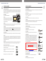
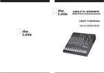
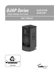
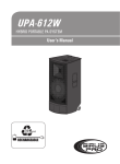
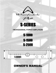
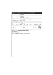
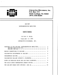
METRO 4700 ST-USB
USER' S MANUAL
ALL-IN-ONE PORTABLE POWERED
SPEAKER SYSTEM
METRO 4700 ST-USB
METRO4700ST-USB
METRO 4700 ST-USB
METRO 4700 ST-USB
GUARANTEE
Topp Pro guarantees the normal operation of the product against any defect of manufacture
and/or vice of material, by the term of (12) months, counted as of the date of purchase on
the part of the user, committing itself to repair or to change, to its election, without position
some, any piece or component that will fail in normal conditions of use within the mentioned
period.
This guarantee is valid if the original buyer will have to present /display this certificate
properly sealed and signed by the selling house, accompanied by the corresponding invoice
of purchase where it consisted the model and serial number of the acquired equipment.
The guarantee does not cover:
- Damages caused by the illegal use of the product, repair and / or nonauthorized modification
conducted by people by Topp Pro.
- Damages caused by the connection of the equipment to other equipment different from
t he specified ones in the manual of use, or by bad connection to these last ones.
- Damages caused by electrical storms, blows and / or incorrect transport.
- Damages caused by excesses or falls of tension in the network or by connection to
netw orks with a tension different from the required one by the unit.
- Damages caused by the presence of sand, acid of batteries, water, or any strange
elem ent inside the equipment.
- Deteriorations produced by the course of the time, use and/or normal wear of the unit.
- Alteraion or absence of the serial number of factory of the equipment.
The repairs could only be carried out the authorized technical service by Topp Pro, that will
inform about the term and other details into the repairs to take place according to this guarantee.
Topp pro, will repair this unit in counted a term nongreater to 30 days as of the date
of entrance of the unit to the Technical Service. In those cases in that due to the
particularity of the spare part, outside necessary their import, the repair time and the
viability of the same one will be subject to the effective norms for the import of parts,
in which case one will inquire to the user about the term and possibility into repair.
With the object of its correct operation, and of the validity of this one guarantee, this
product will have to be installed and to be used according to the instructions that are
detaile d in the manual associate or the package of the product.
This unit will be able to appear for its repair, next to the invoice of purchase (or any other
comprobante where the date of purchase consists), to its authorized distributer Topp Pro or
an authorized technical center on watch by Topp Pro.
Exclusion of damages:
THE RESPONSIBILITY OF TOPP PRO BY ANY DEFECTIVE PRODUCT IS LIMITED THE REPAIR OR THE
REPLACEMENT OF HE HIMSELF, TO TOPP OPTION PRO. IF WE CHOSE TO REPLACE THE PRODUCT,
THE REPLACEMENT CAN BE A RECONDITIONATED UNIT. TOPP PRO WILL NOT BE RESPONSIBLE
BY THE DAMAGES BASED ON THE LOST, INCONVENIENCE, LOSS OF USE, BENEFITS, LOST
SAVINGS, BY THE DAMAGE TO OTHER EQUIPMENT OR OTHER ARTICLES IN THE USE SITE,
OR BY ANY OTH ER DAMAGE IF HE IS FORTUITOUS, CONSEQUENT OR OF ANOTHER TYPE,
ALTHOUGH TOPP PRO HAS BEEN NOTICED OF THE POSSIBILITY OF SUCH DAMAGES.
9
Some states do not allow to exclusion or the limitation to the fortuitous or consequent
damages, so the aforesaid limitation can not be applied to you.
This guarantee gives specific legal rights him, you can also have other right that varies of
state to state.
12
METRO 4700 ST-USB
8
METRO 4700 ST-USB
TECHNICAL SPECIFICATION
Type
System section
Input channels
Impedance
THD
Channel
equalization
TABLE OF CONTENTS
2-way coaxial vented powered speaker
Input type
XLR/RCA/3.5mm jack Mp3 , CD/6.3mmjack
1. INTRODUCTION.........................................................................................1
Input impedance
Line 47k Ohms-input/Mic 1k Ohms-input
2. FEATURES..................................................................................................1
Display LEDs
Power on/Clip
3. USEFUL DATA............................................................................................1
External controls
Volume/compressor SW/phantom power SW
4. CONTROL ELEMENTS................................................................................3
Mic input
Electrically balanced, discrete input
5. INSTALLATION AND CONNECTIONS..........................................................8
Frequency response
20Hz-20KHz, +/-1dB
6. PRESETS & FREQUENCY RESPONSE CURVE...............................................9
Gain
55dB
7. BLOCK DIAGRAM ................................................................................... 10
SNR
>75dB
Line input
Electrically balanced
Frequency response
20Hz-20KHz, +/-1dB
Gain
25dB
Mic input
1.5k Ohm
All other input
10k Ohm or greater
Tape out
1k Ohm
All other output
120 Ohm
<0.03%
Hi shelving
+/-15dB@10KHz
Low shelving
+/-15dB@100Hz
+/-15dB@63Hz
+/-15dB@160Hz
+/-15dB@400Hz
Master
equalization
(7-band EQ)
+/-15dB@1KHz
+/[email protected]
+/[email protected]
+/-15dB@16KHz
DSP section
A/D & D/A converters
24-bit
DSP resolution
24-bit
Type of Effects
Echo, Echo+Verb, Tremolo, Plate, Chorus, Vocal,
Rotary, Small Room, Flange+Verb & Large Hall
Presets
100
Controls
100-position PRESET selector /Clip LED /Mute
Switch with LED indicator
8. TECHNICAL SPECIFICATION.....................................................................11
9. GUARANTEE ...........................................................................................12
METRO 4700 ST-USB
INTRODUCTION
Thank you for purchasing the METRO 4700 ST-USB powered speaker syst em. Thi s Uniqu e syste m
was designed to be an all-in-one portable solution with a built-in 250Wamplifier, 6 channels mixer
with EQ and 24-Bit DSP effects.
The METRO 4700 ST-USB combines practicality with top design concepts achieved over many years
of manufacturing quality products. Please read this manual carefull y so you can take advan tages
of all the features of the METRO 4700 ST-USB.
Thank you again for making th right choice in purchasing the METRO 4700 ST-USB.
FEATURES
*Portable MDF painted cabinet with wheel
*2-way coaxial vented powered speaker
*2*12" woofer and 2*1" throat ferrite driver
*6-CH stereo mixer with a total of 6 inputs, balanced XLR and TRS inputs
*7-band graphic EQ
*ultra low noise discrete mix pre-amps with +15V phantom power
*2-band EQ on stereo input channels
*independent level controls on each channel
*high headroom for excellent dynamic range
*on-stage monitor mix
*FX send for built-in or external effects
*Tape in/out/USB player
*24-bit DSP effects with 100 presets
*lamp socket
*mini plug input for portable players with level control
USEFUL DATA
Please write your serial number here for future reference.
Serial Number:
Data of Purchase:
Purchased at:
METRO 4700 ST-USB
BLOCK DIAGRAM
METRO 4700 ST-USB
METRO 4700 ST-USB
HOOKUP DIAGRAM
PRESETS & FREQUENCY RESPONSE CURVE
00~09
Vocal
Simulate a small space
with slight decay time.
Rev. Decay time: 0.8~0.9S
pre-delay:0-45ms
10~19
Small room
Simulate a bright studio
room
Decay time: 0.7~2.1S
pre-delay:20-45ms
Large hall
Simulate a large acoustic
space of the sound
Decay time: 3.6~5.4S
pre-delay:23-55ms
Echo
Reproduce the sound in
input on the output after
a lapse of time or delay
Delay time: 145~205mS
20~29
30~39
Matching with passive speaker
Make all initial connection with all the equipment powered off, and make sure that the main
volume controls are turned down completely.
1) with a high quality signal line connect a CD player or other players to the active speaker
METRO 4700 ST-USB.
2)using the speaker cable connect th e INPUT of the unit to its OUTPUT.
3)complete other connections as illustrated.
And then turn th e power on.
4)turn up the volume controls of the unit to
about 70%.
5)use the mixer PFL function of the unit to get
the proper input level, and adjust the Main
Mix Level control to manipulate output level.
METRO 4700ST-USB
700W amplifier
TAC-MP3-T
PAN
PAN
PAN
PAN
STEREO
RIGHT
LEFT
RIGHT
LEFT
RIGHT
LEFT
RIGHT
LEFT
88
2
1
2
3
1
2
1
2
3
3
1
3
L
R
ON
OFF
40~49
Echo+verb
50~59
Flange +verb
60~69
Plate
70~79
Simulate to play with another
person carrying out same the
notes on the same instrument
and reverb
Rotary +GTR
90~99
Tremolo +GTR
Delay time: 1.5-2.9ms
rate: 0.8Hz~2.52Hz
Simulate the transducers sound
like classic bright vocal plate
Decay time:0.9-3..6s
Recreate the illusion of
more than on instrument
from a single sound.
Rate: 0.92Hz~1.72Hz
Simulate sound effect
achieved by rotating horn
speakers and a bass cylinder.
Modulation depth:
20%-80%
Chorus+GTR
80~89
Delay time: 208~650ms
Delay time: 1.7-2.1s
Echo with room effect
amplitude modulation
of the signal
When put Mixer on the bracket to adjust the
volume, you can insert the connector into the
TO MIX jack, this unit can work on the normal
condition.
Matching with passive speaker
in this example, it connects a sub-woofer, and the woofer of this two full-range act like midwoofer. This is very popular combination especially in small size clubs where there is no need
for two sub-woofers.
rate: 0.6Hz~5Hz
METRO 4700 ST-USB
+110
T
METRO 4700ST-USB
700W amplifier
TAC-MP3-T
+100
PAN
PAN
PAN
PAN
STEREO
RIGHT
LEFT
RIGHT
LEFT
RIGHT
LEFT
RIGHT
LEFT
88
2
1
3
d
B
S
P
L
+90
1
3
2
1
3
2
1
3
L
R
ON
OFF
+80
+70
+60
20
50
100
200
500
1k
Hz
Sweep
Trace
Color
Line Style Thick
Data
1
2
1
1
Red
Blue
Solid
Solid
Anlr.Bandpass Left
Anlr.Bandpass Left
3
3
Axis
Comment
METRO4700ST-USB-APP PASSIVE
METRO4700ST-USB-APP ACTIVE
Frequency Response.at2
9
2
2k
5k
10k
20k
METRO 4700 ST-USB
METRO 4700 ST-USB
INSTALLATION AND CONNECTIONS
CONTROL ELEMENTS
MIXER SECTION
Sleeve
1- STEREO INPUT CHANNELS
Ring=Return Signal
Tip
Ring
Strain Clamp
Ch1through Ch4, come with balanced MIC IN & LINE IN connectors.
User the XLR (MIC IN) socket to connect a low impedance microphone
or low level signal, which ]also features +15V phantom power
allowing you to connect a condens er micr ophone. Use th e 1/4"
TRS (LINE IN) jack to connect either a microphone or a line level
instrument such as synthesizers, drum machines, effect processors
or any other line level signal.
Tip=Send Signal
5
Sleeve=Ground/Screen
Use for Insert Points
6
1/4" Stereo (TRS) Jack Plug
4
Note: you shall never connect an unbalanced microphone to XLR
socket if you do not want to damage both t he microphone or
the unit.
2=Hot(+)
PAN
7
2- +15V phantom power
RIGHT
LEFT
This switch will apply +15 volt phantom power only to the 4 XLR
input sockets. When these XLR sockets are connected with devices
that do not require phantom power, please make sure the phantom
power is turned off, otherwise, this may damage the device and
monitor.
3
2
1
3
1=Ground/Screen
2
2=Hot(+)
1
3
1=Ground/Screen
3=Cold(-)
3=Cold(-)
Use for Balanced Mic Inputs
(For unbalanced use, connect pin 1 to 3)
Use for Main output
(For unbalanced use, leave pin3 unconnected)
3-pin XLR Male Plug
3-pin XLR Line Socket
(seen from soldering side)
(seen from soldering side)
8
Ring=Return Signal (Connected together)
3- Channel level control
To Channel Insert
This control is used to adjust the overall level of volume for respective
channel. The adjustable range goes from - to +10dB.
1
2
4- DSP/FX AUX1 POST CONTROL
Sleeve=Ground/Screen
1
3
This control is configured as a post-fader, so the audio signal will
be affected by the channel level control. Via the FX SEND socket,
the AUX1 signal can be sent to an external effect device.
Tip=Signal
To Tape or FX Input
Sleeve=Ground/Screen
'Tapped' Connection Direct Output Lead
(Enables the Insert to be used as a Direct Output
while maintaining the channel signal flow)
EQUALIZER
METRO 4700 ST-USB features a 2-band equalizer with allows you
to adjust the high, mid and low freque ncies s eparate ly on e ach mono channel.
To Processor Input
5- HIGH
this is the treble control. You can use it to get rid of high frequency noises or to boost t he sound
of cymbals or the high harmonics of the human voice. The gain range goes from -15dB to +15dB
with a center frequency of 12kHz.
Sleeve=Ground/Screen
To Channel Insert
6- LOW
this is the bass control. It is used to boost male voice or kick-drum and bass guitar. Your system
will sound much bigger than what it is. The g ain rang e goes fr om -15dB to +15dB with cen ter
frequency of 80Hz.
7- Pan control
abbreviation of PANORAMA control for mono a nd s tere o ch anne ls. It is used to deter mine the
amount of channel signal sent to main mix left an d right outputs. Keeping this control in center
position, the signal will be positioned in middle of "stereo field". Turn this control fully counterclockwise,
the signal will be present only on the left of main mix and vice-versa.
3
Tip=Send Signal
Tip
Sleeve
Ring
Ring=Return Signal
To Processor Output
Y-Stereo lead for insert Connection
(To be used when the processor does not employ a
single jack connection for the In/Out Connections)
USB Connection
8
METRO 4700 ST-USB
METRO 4700 ST-USB
CONTROL ELEMENTS
CONTROL ELEMENTS
USB-MP3 PLAYER SECTION
The file system of USB memory for USB-MP 3 player is FAT16 and FAT 32. The player can only decode
MP 3. It can have 7 rank subordinate folders at most, and the maximum quantity of folders within
mp3 files is 24. In the whole USB mem ory, the tota l folders can not exceed 256 (including those
folders without mp3 songs).
8- PEAK/SIGNAL LED
39
38- USB PORT
For connecting with USB memory.
39- PRE
In pause state, press this button it will go to the
previous song and keep in pause state. In play
state, press this button, it will go to the previo us
song and start playing.
38
40
41
9- Level control
This control is used to adjust the level of TAPE IN and 3.5mm jack signal simultaneously adjustable
range goes from - to +10dB.
10- 3.5mm jack
This insert can be used to connect with a computer, mp3, mo4 or CD player.
TAC-MP3-T
42 43 44
40- NEXT
In pause state, press this button it will go to the next song and keep in pause state. In play state,
press this button, it will go to the next song and start playing.
41- REPEAT
Press this button the player will change between the following four modes. REP ALL means repeat
all songs in the memory, the mark on the screen is
.REP1 means to repeat one song, the mark
on the screen is
. Play in order means to play the songs according t o the o rder, the mark on
the screen is blank. Random p lay means to play the songs at random, the mark on the screen is A.
42- PLAY/PAUSE
in play state, press this button to pause the player. In pause state, press this b utton to start playing.
43- STOP
in play state, press stop button to stop playing and the whole quantity of MP 3 songs in the USB
memory will display on the screen. In stop state, press the PRE/NEXT button or press the stop
button again to go to the first song and the player will keep in pause state, t hen press down the
PLATY/PAUSE button to play it.
44- POWER
When the unit is off, press this button & hold for about 2 or3 seconds to turn on the power supply
of the player. Repeat the above operation, you can turn off the power supply of the player.
Note: basic interface instruction
When the player isn't connected to a USB memory equipment,
the interface is as follows:
When the player is searching for MP 3 songs, the interface is
as follows.
When the player is in pause state, the interface is as follows:
When the player is in use, the interface is as follows:
This LED will illuminate green when a signal is present at the LINE/MIC input. When the signal nears
clipping, the LED will illuminate red.
11- TAPE IN
The METRO 4700 ST-SUB features dual RCA jacks(L & R). If you wish to listen to your monitor from
a tape recorder, DAT, or cassette, please use these tape input jacks.
12- TAPE OUT
via the se jacks, you can route the main out signal into a tape recorder or DAT recording.
13- MONITOR CONTROL
This control is used to adjust the level of monitor output.
14- LAMP SWITCH
by pressing this key, you can turn the lamp on/off.
15
15- 12V LAMP
A BNC-type lamp socket is provided for use with a goose-neck lamp.
14
16- GRAPHIC EQ
METRO 4700 ST-USB is equipped with a graphic EQ, which provides
7-band fader controls. Via these faders, you can boost or attenuate
the selected frequency by 15dB at a preset bandwidth. When all
faders are at the center position, the output of the equalizer is at
the flat response. They are used to modify the frequency " contour"
of a sound. The EQ function will be activated a utomatically as
soon as you operate this unit.
13
9
The automatic feedback locator function will be activated in main
mix signal path. When a frequency band fader lights up, it means
the level of this frequency
too high, which may result in
Esto hay band
que is
eliminarlo
unpleasant speaker" howling" or " whistling". In this case, in order
to eliminate feedback, you need to turn dow the corresponding
fader.
17- LEVEL CONTROL (IN graphic EQ SECTION)
This control is used to adjust the output level. The adjustable range
goes from to +10dB.
2
10
11
12
L
R
18- OUTPUT LEVEL LED
The 4-segment LED meter is used to indicate the output level.
19- POWER LD
This LED lights up when the unit is powered on.
7
4
METRO 4700 ST-USB
METRO 4700 ST-USB
CONTROL ELEMENTS
CONTROL ELEMENTS
20- MAIN OUT
Tthis jack is used to output the main mix signal to an external unit.
27- PROGRAM(PUSH)
Adjust this knob to select the right effect you wish to perform. There are total 100 options for you:
vocal, echo, plate and versatile two-effect combination. When you are satisfi ed with t he chose n
preset, please push this knob to store this preset.
21- MONITOR OUT
This jack is used to connect input signal of an external monitor amplifier or active monitor speaker.
22- COMP/LIM SWITCH
set this switch to "ON" position in order to prevent your signal from exceeding a level th resh old
that would cause distortion. This switch is user defeatable and can be in the "ON" or "OFF" position
depending on your preference.
23- FOOT SWITCH
you can connect an external footswitch to turn the onboard effect module on/off, vi a th e 1/ 4"
phone jack.
24- FX SEND jack
this jack is used to send out the signal from AUX bus.
28- DSP MUTE BUTTON
This button is used to activate/deactivate the effect facility. Sometimes, you can also use the FOOT
SWITCH jack for convenient operation.
29- CLIP/MUTE LED
This LED lights up when the input signal is too st rong. I n case of the digital effect module being
muted, this LED also lights up.
30- AUX/DFX RET CONTROL
This control is used to adjust the volume of FX RETURN and MAIN OUTPUT effect.
31- USB OUTPUT
With this switch, the signal of USB can be selected to input in to CH 4 or TO CH 5-6.
REAR PANEL
19
STEREO
16
32- POWER ON/OFF SWITCH
switched the main unit power on or off.
18
METRO 4700ST-USB
Power Rating Continuous: 350Wx2
110 -120V
17
220 -240V
ON
36
OFF
110-120V~50/60Hz
220-240V~50/60Hz
OUTPUT
26
88
33
PHONE JACK
Tip
Sleeve
24
35
32
AC INPUT
TO MIX
29
34
POWER
MINIMUM SPEAKER LOAD: 4 OHMS
MODEL
SERIAL
FUSE
110-120V T12AL AC250V
220-240V T6.3AL AC250V
RATED POWER CONSUMPTION: 1100W
28
27
25
30
21
20
23
31
ON
OFF
22
37
25- FX RETURN jack
This jack is used to return the sound of an effect unit to the main mix. You can also use it as an
extra auxiliary input.
DSP SECTION WITH 24-BIT DIGITAL EFFECTS
Your unit features a special 100-preset digital effect, for further details please refer to the following
content.
26- DISPLAY
Displays the selected prest.
5
33- AC INPUT
Standard, IEC receptacle connect your unit to main electrical outlet with the supplied power cord.
34- VOLTAGE SELECTOR
There are two kinds of voltages for your operation from this switch you can sel ect the voltage at
115V or 230V.
35- PHONE JACK
These jacks are used to connect METRO 4700 ST-USB passive speakers.
Note: in order to avoid damaging your built-in amplifier, please pay more attention to the impedance
of speaker. Lower load impedances are not permitted.
36- TO MIX
Put the Mixer on the bracket to adjust the volume, you can ins ert the connect or into the To MIX
jack, and the unit can work on normal condition.
37- LIMIT LED
When the output signal distortion exceeds 0.5%, then the red LED (LIMIT) indicator will blink. It will
warn you that the levels of the input signal are too high and may cause distortion. Please at tenuate
the level of the input level.
6