1
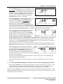
Operating Instructions for the
DG-700
Pressure and Flow Gauge
Operating Instructions for the
DG-700
Pressure and Flow Gauge
The Energy Conservatory
2801 21st Ave. S., Suite 160
Minneapolis, MN 55407
Ph.: (612) 827-1117
Fax: (612) 827-1051
www.energyconservatory.com
Manual Edition May 2012
2012 The Energy Conservatory. All rights reserved.
ENERGY CONSERVATORY WARRANTY
EXPRESS LIMITED WARRANTY:
Seller warrants that this product, under normal use and service as described in the operator’s manual, shall be free from defects in workmanship
and material for a period of 24 months, or such shorter length of time as may be specified in the operator’s manual, from the date of shipment to
the Customer.
LIMITATION OF WARRANTY AND LIABILITY:
This limited warranty set forth above is subject to the following exclusions:
a)
b)
c)
d)
With respect to any repair services rendered, Seller warrants that the parts repaired or replaced will be free from defects in workmanship
and material, under normal use, for a period of 90 days from the date of shipment to the Purchaser.
Seller does not provide any warranty on finished goods manufactured by others. Only the original manufacturer’s warranty applies.
Unless specifically authorized in a separate writing, Seller makes no warranty with respect to, and shall have no liability in connection
with, any goods which are incorporated into other products or equipment by the Purchaser.
All products returned under warranty shall be at the Purchaser’s risk of loss. The Purchaser is responsible for all shipping charges to return
the product to The Energy Conservatory. The Energy Conservatory will be responsible for return standard ground shipping charges. The
Customer may request and pay for the added cost of expedited return shipping.
The foregoing warranty is in lieu of all other warranties and is subject to the conditions and limitations stated herein. NO OTHER EXPRESS
OR IMPLIED WARRANTY IS PROVIDED, AND THE SELLER DISCLAIMS ANY IMPLIED WARRANTY OF FITNESS FOR
PARTICULAR PURPOSE OR MERCHANTABILITY.
THE EXCLUSIVE REMEDY OF THE PURCHASER FOR ANY BREACH OF WARRANTY shall be the return of the product to the factory
or designated location for repair or replacement, or, at the option of The Energy Conservatory, refund of the purchase price.
The Energy Conservatory’s maximum liability for any and all losses, injuries or damages (regardless of whether such claims are based on
contract, negligence, strict liability or other tort) shall be the purchase price paid for the products. IN NO EVENT SHALL THE SELLER BE
LIABLE FOR ANY SPECIAL, INCIDENTAL OR CONSEQUENTIAL DAMAGES. The Energy Conservatory shall not be responsible for
installation, dismantling, reassembly or reinstallation costs or charges. No action, regardless of form, may be brought against the Seller more
than one year after the cause of action has accrued.
The Customer is deemed to have accepted the terms of this Limitation of Warranty and Liability, which contains the complete and exclusive
limited warranty of the Seller. This Limitation of Warranty and Liability may not be amended or modified, nor may any of its terms be waived
except by a writing signed by an authorized representative of the Seller.
TO ARRANGE A REPAIR: Please call The Energy Conservatory at 612-827-1117 before sending any product back for repair or to inquire
about warranty coverage. All products returned for repair should include a return shipping address, name and phone number of a contact person
concerning this repair, and the purchase date of the equipment.
Table of Contents
CHAPTER 1
FEATURE SUMMARY
1.1 Feature List
1
1
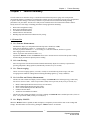
1.1.a Pressure Measurements:
1
1.1.b Auto Zeroing:
1
1.1.c Time Averaging:
1
1.1.d Air Flow and Velocity Measurements:
1
1.1.e Display “HOLD”:
1
1.1.f Specialized @ 50 and @ 25 Leakage Measurement Mode:
2
1.1.g Specialized Air Handler Flow Measurement Mode:
2
1.1.h Automated Blower Door Testing, Cruise Control and Data Logging:
2
1.2 Overview of Gauge Operating Modes
2
1.3 Gauge Face and Buttons
3
1.4 Input/Output Ports on the DG-700
4
1.4.a USB and Serial Communication Ports:
4
1.4.b Fan Control Output Jack:
4
1.4.c AC Power Input Jack:
1.5 Overview of the Time Averaging Feature
4
5
1.5.a Description of Time Averaging Periods:
5
1.5.b Illustration of Time-Averaging Operation (First 10 seconds of operation):
5
1.5.c Resetting the Time Averaging Measurement Buffer:
5
1.6 Overview of the Baseline Pressure Measurement Feature (Channel A)
6
1.6.a Buttons Used with Baseline Pressure Feature:
6
1.6.b Restarting the Baseline Measurement:
7
1.6.c Clearing and Exiting from the Baseline Pressure Procedure:
7
1.7 Auto-Off Feature
CHAPTER 2
PRESSURE/PRESSURE MODE
7
8
2.1 Mode Summary
8
2.2 Overview of Pressure/Pressure Mode
8
2.3 Changing the Pressure Units
8
2.4 Changing the Time Averaging Period
9
2.5 Using the Baseline Pressure Feature
9
2.5.a Example: Measuring Building Depressurization from an Exhaust Fan
CHAPTER 3
PRESSURE/FLOW MODE
9
11
3.1 Mode Summary
11
3.2 Overview of Pressure/Flow Mode
11
3.3 Changing the Selected Test Device and Configuration
11
3.4 “LO” Displayed on Channel B
12
3.5 Changing the Air Flow Units
12
3.6 Changing the Time Averaging Period
12
3.7 Using the Baseline Pressure Feature in Pressure/Flow Mode
12
3.7.a Example: Using the Baseline Feature During a Blower Door Depressurization Test
12
3.7.b Entering Baseline Readings into TECTITE Software When Using the Baseline Feature:
CHAPTER 4
PRESSURE/FLOW @ 50 AND @ 25 MODES
13
14
4.1 Mode Summary
14
4.2 Overview of Pressure/Flow @ 50 and @ 25 Modes
14
4.2.a Pressure/Flow @ 50 Mode:
14
4.2.b Pressure/Flow @ 25 Mode:
14
4.2.c Benefits of Using the @ 50 and @ 25 Modes:
15
4.3 Changing the Selected Test Device and Configuration
15
4.4 “-----”or “LO” Displayed on Channel B
15
4.5 Changing the Leakage Units
16
4.6 Changing the Time Averaging Period
16
4.7 Using the Baseline Pressure Feature in Pressure/Flow Mode
16
4.8 Leakage Estimate Calculations Used in the @ 50 and @ 25 Modes
16
4.8.a @ 50 Mode:
16
4.8.b @ 25 Mode:
17
4.8.c Errors in Leakage Estimates:
17
CHAPTER 5
PRESSURE/AIR HANDLER FLOW MODE
19
5.1 Mode Summary
19
5.2 Overview of Pressure/Air Handler Flow Mode
19
5.3 Changing the Selected Test Device and Configuration
19
5.4 “-----”or “LO” Displayed on Channel B
20
5.5 Changing the Air Handler Flow Units
20
5.6 Changing the Time Averaging Period for the Step 2 Procedure
20
5.7 Test Procedure For Measuring Air Handler Flow
20
5.7.a Step 1: Measuring the NSOP
20
5.7.b Step 2: Measuring the TFSOP and Adjusted Air Handler Flow
21
5.8 Flow Resistance Correction Factors Used in the DG-700
CHAPTER 6
PRESSURE/VELOCITY MODE
22
23
6.1 Mode Summary
23
6.2 Overview of Pressure/Velocity Mode
23
6.3 Changing the Air Velocity Units
23
6.4 Changing the Time Averaging Period
23
6.5 Air Velocity Calculations Used in the DG-700
23
CHAPTER 7
SERVICING AND MAINTENANCE
7.1 Gauge Calibration and Servicing
24
24
7.1.a Calibration:
24
7.1.b Servicing/Repairs:
24
7.2 Low Battery Indicator/Battery Replacement
24
7.2.a Low Battery Indicators:
24
7.2.b Battery Replacement:
24
7.3 Troubleshooting/Resetting the DG-700
25
7.4 AC Power Supply Specifications
APPENDIX A
QUICK GUIDES FOR USING THE DG-700 WITH ENERGY
CONSERVATORY TEST DEVICES
25
26
A.1 One-Point 50 Pascal Building Depressurization Test using the Model 3 Minneapolis Blower Door™
and DG-700 Digital Gauge
26
A.2 One-Point 25 Pascal Total Leakage Duct Pressurization Test Using the Seried B Minneapolis Duct
Blaster and DG-700 Digital Gauge
28
A.3 Using the TrueFlow Air Handler Flow Meter and the DG-700 Digital Gauge
30
A.4 DG-700 Connections Needed to Conduct Automated Blower Door Tests
32
A.5 Using the DG-700's Cruise Control Feature
36
Chapter 1
Chapter 1
Feature Summary
Feature Summary
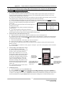
The DG-700 Pressure and Flow Gauge is a multi-functional differential pressure gauge with 2 independent
measurement channels. In addition to providing high resolution pressure measurements, the DG-700 is programmed
to operate with other Energy Conservatory test devices to provide air flow measurements during building
performance test procedures. The DG-700’s dual pressure channels and air flow measurement features make it
ideally suited for a wide range of building performance testing applications including:
Blower Door airtightness testing.
Duct system airtightness testing.
Air handler flow measurements.
Exhaust fan flow measurements.
Building depressurization and combustion safety testing.
1.1 Feature List
1.1.a Pressure Measurements:
-
Simultaneous display of 2 independent differential pressure channels (A and B).
Each pressure channel has a range of –1,250 Pascals to +1,250 Pascals.
Accuracy of pressure channels is +/- 1% of reading, or 2 times the resolution, whichever is greater.
Auto ranging with 0.1 Pascal resolution.
Choice of pressure units (Pascals or Inches w.c.).
Specialized “Baseline” feature on Channel A allows user to measure and record a baseline pressure reading,
and then display the baseline adjusted pressure reading.
1.1.b Auto Zeroing:
-
Auto-zeroing feature for both measurement channels automatically adjusts for sensitivity to position and
operating temperature during operation (automatically activated every 10 seconds).
1.1.c Time Averaging:
-
Choice of 4 time-averaging options (1 second, 5 second, 10 second and Long-Term average). The timeaveraging feature stabilizes readings when measuring fluctuating signals (e.g. windy conditions).
1.1.d Air Flow and Velocity Measurements:
-
The DG-700 will calculate and display air flow readings on Channel B for the following Energy Conservatory
test devices: (choice of units - cubic feet per minute (CFM), meters3 per hour (m3/hr), liters per second (l/s))
-
Model 3 Minneapolis Blower Door™ fans (110V and 220V).
Model 4 Minneapolis Blower Door fans (220V).
Series A and B Minneapolis Duct Blaster® fans.
Exhaust Fan Flow Meter.
TrueFlow® Air Handler Flow Meter.
The DG-700 will calculate and display air velocity readings on Channel B from a standard pitot tube. (choice of
units – feet per minute (FPM), meters per second (m/s))
1.1.e Display “HOLD”:
When the “HOLD” button is pushed, the DG-700 display is temporarily frozen with the most recent readings and
settings. The Hold feature is turned off by pushing the “HOLD” button a second time.
1
Operating Instructions
for the DG700
Chapter 1
Feature Summary
1.1.f Specialized @ 50 and @ 25 Leakage Measurement Mode:
-
For one-point airtightness tests of building and duct systems, the DG-700 will display on Channel B estimated
leakage rates adjusted to either 50 Pascals or 25 Pascals of test pressure.
Choice of leakage units (CFM @, m3/hr @ , l/s @, sq. inches @ , sq. centimeters @).
1.1.g Specialized Air Handler Flow Measurement Mode:
-
Designed for measuring air handler flow rates using a TrueFlow Air Handler Flow Meter or a Duct Blaster fan.
Automatically adjusts displayed air flow rate using measured system operating pressures (NSOP and TFSOP).
Choice of air flow units (cfm, m3/hr, l/s).
1.1.h Automated Blower Door Testing, Cruise Control and Data Logging:
-
The DG-700 can be used along with a computer and specialized TEC software (TECTITE, TECTITE Express
or TECLOG2) to conduct fully automated Blower Door tests.
The Cruise Control feature allows you to automatically control a Blower Door or Duct Blaster fan to maintain a
constant 75Pa, 50 Pa, 25 Pa or 0 Pa building pressure without having the gauge connected to a computer.
Both of the DG-700’s pressure channel readings can be recorded using TEC’s TECLOG2 data logging software.
1.2 Overview of Gauge Operating Modes
Mode
Application
Channel A Display
Channel B Display
Pressure/Pressure
(PR/ PR)
Multi-purpose pressure
measurements.
Pressure in units chosen
(Pa, in w.c.).
Pressure in units chosen
(Pa, in w.c.).
Pressure/Flow
(PR/ FL)
Multi-purpose pressure
and air flow
measurements.
Pressure in Pascals.
Nominal (unadjusted) air flow from the
selected Energy Conservatory test
device, in units chosen (CFM, m3/h, l/s).
Pressure/Flow @ 50 Pa
(PR/ FL@50)
Specialized mode for
one-point Blower Door
building airtightness
test.
Building pressure in Pascals.
Building leakage at 50 Pascals in units
chosen (CFM@50, m3/h@50, l/s@50,
in2@50, cm2@50). Leakage rate is
determined by continuously adjusting
the measured air flow from the selected
Blower Door fan to a building pressure
of 50 Pascals, using the real-time
Channel A building pressure reading.
Pressure/Flow @ 25 Pa
(PR/ FL @25)
Specialized mode for
one-point total leakage
duct airtightness test.
Duct system pressure in
Pascals.
Total duct leakage at 25 Pa in units
chosen (CFM@25, m3/h@25, l/s@25,
in2@25, cm2@25). Leakage rate is
determined by continuously adjusting
the measured air flow from the selected
duct testing fan to a duct pressure of 25
Pascals, using the real-time Channel A
duct pressure reading.
Pressure/AH Flow
(PR/ AH)
Specialized mode for
measuring air handler
flow rates using a
TrueFlow Air Handler
Flow Meter or a Duct
Blaster fan.
Normal system operating
pressure (NSOP) and test
flow system operating
pressure (TFSOP) in Pascals.
Total air handler flow in units chosen
(CFM, m3/h, l/s). Air flow from the
selected Energy Conservatory test
device is continuously adjusted using
the measured NSOP and TFSOP
readings from Channel A.
Pressure/Velocity
(PR/ V)
Pressure and air
velocity measurements.
Pressure in Pascals.
Air velocity in units chosen
(FPM, m/s).
2
Operating Instructions
for the DG700
Chapter 1
Feature Summary
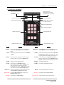
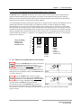
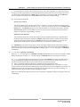
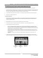
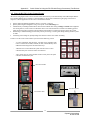
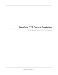
1.3 Gauge Face and Buttons
Selected test device
configuration (for air flow
measurements on Channel B)
Selected test device (for air
flow measurements on
Channel B)
Channel A Reading
Channel B Reading
Selected Time Averaging
(for both Channels)
Selected Operating Mode
Display Hold Indicator
Low Battery Indicator
Channel A Input Tap
Channel B Input Tap
Channel A Reference Tap
Button
DEVICE
UNITS
CONFIG
MODE
Channel B Reference Tap
Purpose
Button
Used to select the Energy Conservatory test device
connected to Channel B (not active in PR/PR
mode).
BASELINE
Initiates Baseline pressure measurement procedure
on Channel A (not active in PR/AH mode).
Selects the pressure and air flow units for Channels
A and B.
START
Used to start measurement procedure for Baseline
and NSOP measurements. Also used to reset time
averaging buffers and manually initiate auto-zero.
Used to select the configuration for the currently
chosen test device (not active in PR/PR mode).
ENTER
Used to accept and enter Baseline and NSOP
pressure readings. After entering Baseline reading,
Channel A will display baseline adjusted pressure.
Selects the current operating mode.
ON/OFF
CLEAR
Used to exit out of a Baseline pressure
measurement procedure. When in PR/AH mode,
resets gauge back to beginning of AH flow
measurement procedure (i.e. NSOP measurement).
Also used to turn off the Cruise Control feature.
LIGHT
TIME AVG
Used to select the time averaging mode (not active
during Baseline and NSOP measurements).
HOLD
Begin Cruise
Initiates Cruise Control feature (not active in
PR/AH and PR/V modes).
Start Fan
Purpose
Stop Fan
Cruise Target
Starts the fan for Cruise Control.
Turns gauge On and Off.
Turns display backlight On and Off.
Turns display Hold feature On and Off.
Turns off the fan for Cruise Control.
Used to select the Cruise Target Pressure.
3
Operating Instructions
for the DG700
Chapter 1
Feature Summary
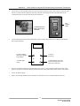
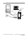
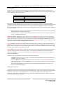
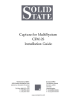
1.4 Input/Output Ports on the DG-700
1.4.a USB and Serial Communication Ports:
The DG-700 contains both a USB and a DB-9 serial communication port, either of which can be used to create a 2way communication link between the gauge and a computer. This communication link can be used (along with TEC
software) to conduct automated Blower Door tests and to data log both pressure channels.
-
Automated Blower Door testing requires the TECTITE, TECTITE Express or TECLOG2 software, a Blower
Door fan speed controller with a communication jack (standard equipment since September 2004), a fan control
cable, and a communication cable (either USB or 9 pin serial) to connect the DG-700 to a user supplied laptop
computer.
-
Data logging of pressure measurements requires the TECLOG2 software (available from
www.energyconservatory.com), and a communication cable (either USB or 9 pin serial) to connect the DG-700
to a user supplied laptop computer.
1.4.b Fan Control Output Jack:
The fan control output jack provides a speed control signal which is used to control a Blower Door or Duct Blaster
fan during an automated Blower Door test, or with the Cruise Control feature. A fan control cable is used to connect
the fan control output jack to the communication jack on the side of the fan speed controller.
1.4.c AC Power Input Jack:
The AC power input jack can be used with an optional AC power supply to provide a long term power source for the
gauge (to be used when data logging). The gauge is normally powered by 6 AA batteries located in the rear battery
compartment. When the AC power supply is plugged in, the power supply bypasses the batteries in the battery
compartment. See Chapter 7 for AC power supply specifications. Note: Always turn off the gauge before plugging
in the AC power supply.
USB
Communication
Port
Serial
Communication
Port
Fan Control
Output Jack
AC Power Input Jack
Communication Jacks
(Blower Door and
Duct Blaster Speed
Controllers)
4
Operating Instructions
for the DG700
Chapter 1
Feature Summary
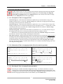
1.5 Overview of the Time Averaging Feature
The DG-700 has a choice of 4 time averaging periods which are applied to both measurement channels.
When the gauge is turned on, the default time averaging period is 1 second average. To change the
selected time averaging period, press the TIME AVG button. The currently selected time averaging
period is shown in the TIME AVG portion of the gauge display.
1.5.a Description of Time Averaging Periods:
-
1 Second Average (1) – Both measurement channels are updated once per second with the average of the
readings from the previous 1 second. The 1 Second Average is the default time averaging period when turning
on the gauge, and is the period most commonly used.
-
5 Second Average (5) – Both measurement channels are updated once every 5 seconds with the average of the
readings from the previous 5 second period. When first activated, the display shows "---" until the first 5 second
measurement buffer has been recorded. The 5 Second Average should be used when the 1 Second Average
reading is fluctuating more than desired.
-
10 Second Average (10) – Both measurement channels are updated once every 10 seconds with the average of
the readings from the previous 10 second period. When first activated, the display will show
"---" until the first 10 second measurement buffer has been recorded. The 10 Second Average mode should be
used when the 5 Second Average reading is fluctuating more than desired.
-
Long Term Average (L) – Both measurement channels are updated once per second with the running average of
all readings taken after the Long Term Average period is activated. When using Long Term Average, the gauge
continuously adds the current measurements to the measurement buffer and displays the average value of all
recorded measurements. The gauge will operate for approximately 2 hours when using Long Term Average
before the measurement buffer is overloaded. When the buffer is overloaded, both channel readings will re-start
a new long-term average period.
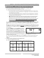
1.5.b Illustration of Time-Averaging Operation (First 10 seconds of operation):
1 Second Average:
Seconds: 1
2
3
5 Second Average:
4
5
6
7
8
9
10
Seconds: 1
2
3
4
Pressure 12 5 10 2
Signal:
6 15
8 12
2
6
Pressure 12 5 10 2
Signal:
Display: 12 5 10 2
6 15
8 12
2
6
Display: -- --
10 Second Average:
Seconds: 1
2
3
-- -- --
6
6 15
-- 7
7
8
8 12
9
10
2
6
7
7
7
7
9
6
7
8
Long Term Average:
4
Pressure 12 5 10 2
Signal:
Display:
--
5
5
6
6 15
-- -- --
7
9
10
8 12
8
2
6
--
-- 8
--
Seconds: 1
9
10
Pressure 12 5 10 2
Signal:
2
3
4
6 15
8 12
2
6
Display: 12 9
7
8
8
8
9 7
5
8
9
1.5.c Resetting the Time Averaging Measurement Buffer:
When using the 5 second, 10 second or Long Term averages, it is sometimes desirable to reset and
restart the time averaging measurement buffer when an unwanted signal has been recorded during a time
averaging period (e.g. someone steps on the tubing during a Long Term Average measurement). To reset
and restart the time averaging measurement buffer for both channels, press the START button.
5
Operating Instructions
for the DG700
Chapter 1
Feature Summary
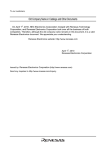
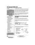
1.6 Overview of the Baseline Pressure Measurement Feature (Channel A)
The Baseline feature on Channel A allows the user to measure and record a baseline pressure reading, and then
display the baseline adjusted pressure on the gauge. For purposes of this manual a baseline pressure reading is
defined as a pressure measurement made under a specific operating condition, which will be used to determine the
change in pressure created by a change in the operating condition.
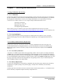
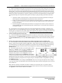
A common building performance application requiring use of a baseline pressure reading is determining the extent of
building depressurization caused by turning on an exhaust fan. In order to accurately quantify the building
depressurization, the user first needs to know the building pressure (with reference to outside) prior to the exhaust
fan being turned on. This initial pressure reading, known as the baseline building pressure, can be quickly measured
and then used to adjust the final building pressure reading (after the exhaust fan is turned on) to determine the actual
change in building pressure caused by fan operation. In the example below, the building depressurization measured
from the exhaust fan operating is –4.2 Pascals (i.e. the building pressure changed from –2.6 Pa to –6.8 Pa when the
exhaust fan was turned on).
0
-1
Change in Building
Pressure From
Turning On an
Exhaust Fan (Pa)
-2.6
-2
-3
-4
-5
-4.2
Baseline
Building
Pressure
(Fan Off)
-6.8
-6
-7
Building
Pressure
(Fan On)
Baseline
Adjusted
Building
Pressure
(Change from
Turning Fan On)
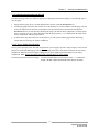
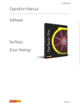
1.6.a Buttons Used with Baseline Pressure Feature:
Pressing the BASELINE button initiates the baseline
pressure measurement feature. The word
“BASELINE” will begin to flash in the Channel A
display, indicating that the baseline feature is active. At this
point, the gauge is monitoring the real-time Channel A pressure
reading, but is not recording the reading. The Channel B display
is not active at this time.
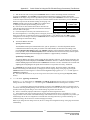
Press the START button to begin recording a
baseline pressure reading. Once the START button
is pressed, the word “BASELINE” stops flashing and
the gauge begins recording a long term average baseline
pressure reading on Channel A. During the baseline
measurement procedure, the Channel B display is used as a
timer to let the user know how long (in seconds) the baseline
measurement has been active. The longer the measurement time, generally the more stable the baseline reading
typically becomes.
6
Operating Instructions
for the DG700
Chapter 1
Feature Summary
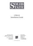
Once you are satisfied with the baseline pressure
reading, press the ENTER key to accept and enter
the baseline pressure reading into the gauge. After
pressing ENTER, Channel A will now display the baseline
adjusted pressure reading (i.e. the measured baseline pressure
reading will be subtracted from the current Channel A pressure
measurement). The icon “ADJ” appears in the Channel A display to indicate that the baseline adjusted pressure
reading is displayed. The time averaging period for the gauge reverts back to whatever period was selected prior to
pressing the BASELINE button. In addition, Channel B also reverts back to displaying an unadjusted pressure
reading.
Now create a change in the operating condition of the building
(e.g. turn on and exhaust fan). Channel A will display the
change in building pressure caused by the change in operating
condition.
1.6.b Restarting the Baseline Measurement:
During a baseline measurement procedure (i.e. while the gauge is recording the long term average
baseline pressure), the baseline measurement procedure can be restarted by pressing the START button.
When START is pressed, the measurement buffer and time counter for the baseline reading is cleared
and a new baseline reading is immediately started.
Once a baseline measurement has been taken and entered into the gauge (i.e. ADJ appears below the
Channel A reading), a new baseline measurement procedure can be initiated by pressing the
BASELINE button.
1.6.c Clearing and Exiting from the Baseline Pressure Procedure:
Pressing the CLEAR button clears the baseline measurement buffer and turns the baseline feature off.
The gauge will remain in the operating mode selected prior to the BASELINE button being pressed.
Note: If the gauge Mode is changed while the baseline measurement feature is active, the baseline measurement
buffer is cleared and the baseline feature is turned off.
1.7 Auto-Off Feature
In order to preserve battery life, the DG-700 gauge will automatically shut off if no keys are pressed for 2 hours. The
auto-off feature can be disabled by simultaneously pressing the CLEAR and ENTER buttons. The auto-off feature
is automatically re-enabled whenever the gauge is turned off and then back on.
7
Operating Instructions
for the DG700
Chapter 2
Chapter 2
Pressure/Pressure Mode
Pressure/Pressure Mode
2.1 Mode Summary
Mode
Application
Channel A Display
Channel B Display
Pressure/Pressure
(PR/PR)
Multi-purpose
pressure
measurements.
Pressure in units chosen
(Pa, in w.c.).
Pressure in units chosen
(Pa, in w.c.).
2.2 Overview of Pressure/Pressure Mode
The DG-700 gauge is turned on by pressing the
ON/OFF button once. When first turned on, the gauge
is automatically placed in the Pressure/Pressure
(PR/PR) operating mode and immediately begins monitoring and
displaying pressure readings for both Channels A and B. The
default pressure units for both channels is Pascals, and the default
time averaging period is 1 second average.
Each channel on the DG-700 measures the pressure difference between either of the top Input pressure taps and its
corresponding bottom Reference pressure tap. The gauge can monitor and display both positive and negative
pressure readings (i.e. bi-directional). In order to display the correct "sign" of the pressure reading (i.e. positive or
negative), it is important that the pressure taps are used consistently and logically. The top Input taps should always
be connected to the pressure signal(s) you are trying to measure. The bottom Reference taps should always be
connected to the reference pressure(s) you are measuring the pressure signal with reference to.
For example, let's set up the gauge to measure the pressure in a house with reference to outside using Channel A. If
you are standing in the house, connect tubing to the Channel A Reference tap and run it outside, while leaving the
Channel A Input tap open to the house. The gauge will now display the pressure difference between the house and
outside, along with the correct sign of the reading. If the house is at a lower pressure than outside (e.g. from an
exhaust fan running), then the pressure reading displayed on the gauge will have a minus sign "-" in front of the
reading.
On the other hand, if you are standing outside and wish to make the same reading, connect a piece of tubing to the
Channel A Input tap and run it into the house, while leaving the Channel A Reference tap open to the outside. The
gauge will now display the same house to outside pressure difference as above, along with the correct sign. Note: In
either case, if you had connected the tubing to the wrong tap on Channel A, the display would show the correct
differential pressure reading, however, the reading would have the wrong sign.
2.3 Changing the Pressure Units
When in the PR/PR operating mode, the DG-700 can display pressure readings in units of Pascals or
inches w.c.. The default pressure units for the gauge is Pascals for both Channels A and B. To change
the pressure units for both channels, press the UNITS button. The selected pressure units are shown on
the gauge display directly below each of the channel readings.
8
Operating Instructions
for the DG700
Chapter 2
Pressure/Pressure Mode
2.4 Changing the Time Averaging Period
The DG-700 has a choice of 4 time averaging periods which are applied to both pressure measurement
channels. The default time averaging period is 1 second average. To change the selected time averaging
period, press the TIME AVG button. The selected time averaging period is shown in the TIME AVG
portion of the gauge display. (See Section 1.5 for an overview of the time averaging feature).
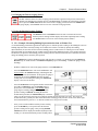
2.5 Using the Baseline Pressure Feature
The Baseline feature on Channel A allows the user to measure and record a
baseline pressure reading, and then display the baseline adjusted pressure reading.
(See Section 1.6 for an overview of the baseline pressure feature)
2.5.a Example: Measuring Building Depressurization from an Exhaust Fan
A common building performance application requiring use of a baseline pressure reading is determining the extent of
building depressurization caused by turning on an exhaust fan. In order to accurately quantify the building
depressurization, the user first needs to know the building pressure (with reference to outside) prior to the exhaust
fan being turned on. This initial pressure reading, known as the baseline building pressure, can be quickly measured
and then used to adjust the final building pressure reading (after the exhaust fan is turned on) to determine the actual
change in building pressure caused by fan operation.
-
Set up Channel A to measure building pressure with reference to outside (e.g. run tubing from the Channel A
Reference tap to outside and leave the Channel A Input tap open to the building – assumes the gauge is in the
building).
-
With the exhaust fan off, turn on the gauge and leave it in the PR/PR mode.
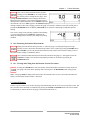
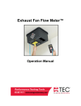
-
Press the BASELINE button. The word “BASELINE” will
begin to flash in the Channel A display, indicating that the
baseline feature has been initiated. At this point, the gauge is
monitoring the real-time Channel A baseline pressure
reading, but is not recording the reading. The Channel B
display is not active at this time.
-
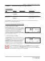
Press the START button to begin the baseline measurement
procedure on Channel A. Once the START button is
pressed, the word “BASELINE” stops flashing and the
gauge begins recording a long term average baseline
pressure reading on Channel A. During the baseline
measurement procedure, the Channel B display is used as a
timer to let the user know how long (in seconds) the baseline measurement has been active. The longer the
measurement time, generally the more stable the baseline reading typically becomes. In the screen to the right,
the measured baseline pressure is –2.6 Pascals (measured over the past 45 seconds).
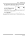
-
Once you are satisfied with the baseline pressure reading,
press the ENTER key to accept and enter the baseline
pressure reading into the gauge. After pressing ENTER,
Channel A will now display the baseline adjusted pressure
reading (i.e. the measured baseline pressure reading will be
9
Operating Instructions
for the DG700
Chapter 2
Pressure/Pressure Mode
subtracted from the current Channel A pressure measurement). The icon “ADJ” appears in the Channel A
display to indicate that the baseline adjusted pressure reading is displayed. The time averaging period for the
gauge reverts back to whatever period was selected prior to pressing the BASELINE button. Note: At this
point, Channel B also reverts back to displaying an unadjusted pressure reading.
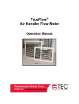
-
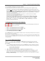
Turn on the exhaust fan. Channel A will now display the
actual change in building pressure created by the exhaust
fan. In the screen to the right, the building depressurization
measured from the exhaust fan operating is –4.2 Pascals
(i.e. the building pressure changed from –2.6 Pa to –6.8
Pa when the exhaust fan was turned on).
-
While displaying the baseline adjusted pressure on Channel A, the user can change the selected time averaging
period if the pressure reading is fluctuating more than desired.
-
Channel B can be used to simultaneously measure any other unadjusted pressure signal, such as the flue
pressure in a combustion appliance.
Note: Pressing the CLEAR button clears the baseline measurement buffer and turns the baseline feature off. If the
gauge Mode is changed while the baseline measurement feature is active, the baseline measurement buffer is cleared
and the baseline feature is turned off.
10
Operating Instructions
for the DG700
Chapter 3
Chapter 3
Pressure/Flow Mode
Pressure/Flow Mode
3.1 Mode Summary
Mode
Application
Channel A Display
Channel B Display
Pressure/Flow
(PR/ FL)
Multi-purpose
pressure and air flow
measurements.
Pressure in Pascals.
Nominal (unadjusted) air flow from the
selected Energy Conservatory test
device, in units chosen (CFM, m3/h, l/s).
3.2 Overview of Pressure/Flow Mode
The Pressure/Flow mode is a multi-purpose mode used to
measure a test pressure on Channel A while simultaneously
measuring air flow from an Energy Conservatory test device on
Channel B. The Pressure/Flow mode a very versatile operating
mode and is typically used whenever simultaneous pressure and
air flow measurements are needed (except when using the
specialized PR/ FL@50, PR/ FL@25 and PR/ AH modes).
To select the Pressure/Flow mode, press the MODE button until the selected operating mode shown on
the gauge display is PR/ FL. When first entering this mode, the default pressure units on Channel A is
Pascals, the default air flow units on Channel B is CFM (cubic feet per minute), and the default selected
test device is the Model 3 (110V) Minneapolis Blower Door. The default time averaging period is 1 second average.
3.3 Changing the Selected Test Device and Configuration
The DG-700 can display air flow from the following Energy Conservatory test devices on
Channel B:
Model 3 (110V) Minneapolis Blower Door™ fans (BD 3).
Model 3 (220V) Minneapolis Blower Door™ fans (BD 3 220).
Model 4 (220V) Minneapolis Blower Door fans (BD 4).
Series A Minneapolis Duct Blaster® fans (DB A).
Series B Minneapolis Duct Blaster® fans (DB B).
Exhaust Fan Flow Meter (EXH).
TrueFlow® Air Handler Flow Meter (TF).
Press the DEVICE button to toggle through the available test devices. The currently selected test device is shown in
the Device section of the gauge display. The Model 3 (110V) Minneapolis Blower Door is the default test device
when first entering the PR/ FL mode.
Once a test device is selected, the configuration of the device (i.e. flow rings, door position or plate installed) can be
selected by pressing the CONFIG button. The currently selected device configuration is shown in the Config section
of the gauge display.
11
Operating Instructions
for the DG700
Chapter 3
Pressure/Flow Mode
3.4 “LO” Displayed on Channel B
Whenever “LO” appears on Channel B in the PR/ FL mode, the pressure signal from the test device is too low to
provide a reliable air flow reading. The message “LO” appears on the Channel B display under the following two
conditions:
“LO” is continuously displayed on Channel B when there is negligible air flow through the test device.
“LO” alternates with a flow reading when the air flow reading through the device is unreliable (i.e. you are
trying to measure a flow outside of the calibrated range of the test device in its current configuration). If
possible, the user should change the test device configuration to match the flow rate being measured (e.g. install
a flow ring or a smaller flow ring).
3.5 Changing the Air Flow Units
When in the PR/ FL operating mode, the DG-700 can display air flow readings on Channel B in units of
CFM, m3/hr, or l/s. The default air flow unit is CFM. To change the air flow unit for Channel B, press
the UNITS button. The selected air flow units are shown on the gauge display directly below the
Channel B readings. The pressure unit for Channel A is always Pascals when in the PR/ FL mode.
3.6 Changing the Time Averaging Period
To change the selected time averaging period for both Channel A and B, press the TIME AVG button.
The selected time averaging period is shown in the TIME AVG portion of the gauge display. (See
Section 1.5 above for a complete description of the time averaging periods.)
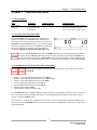
3.7 Using the Baseline Pressure Feature in Pressure/Flow Mode
The Baseline feature on Channel A allows the user to measure and record a
baseline pressure reading, and then display the baseline adjusted pressure reading.
This feature is commonly used during both building and duct airtightness test
procedures where the user wishes to display the actual change in building or duct pressure caused by operation of the
Blower Door or duct airtightness testing fan. In order to accurately determine the change in pressure from the test
fan, the user first needs to know the building or duct system pressure (with reference to outside) prior to the test fan
being turned on. This initial baseline pressure reading can be quickly measured and then used to adjust the test
pressure readings to determine the actual change in pressure caused by operation of the Blower Door or duct
airtightness test fan. (See Section 1.6 for an overview of the baseline pressure feature)
3.7.a Example: Using the Baseline Feature During a Blower Door Depressurization Test
-
Set up Channel A to measure building pressure with reference to outside (e.g. run tubing from the Channel A
Reference tap to outside and leave the Channel A Input tap open to the building – assumes the gauge is in the
building). Run tubing from the Channel B Input tap to the pressure tap on the Blower Door fan.
-
With the Blower Door off and the No-Flow Plate installed, turn on the gauge and put it the PR/ FL mode by
pressing the MODE button.
-
Select the Blower Door fan device you will be using by pressing the DEVICE button (Model 3 fan is the default
test device when entering the PR/ FL mode).
12
Operating Instructions
for the DG700
Chapter 3
Pressure/Flow Mode
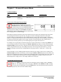
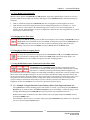
-
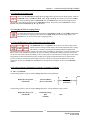
Press the BASELINE button. The word “BASELINE” will
begin to flash in the Channel A display, indicating that the
baseline feature has been initiated. At this point, the gauge is
monitoring the real-time Channel A baseline building
pressure (i.e. the existing building pressure caused by stack
and wind effects), but is not recording the reading. The
Channel B display is not active at this time.
-
Press the START button to begin the baseline measurement
procedure on Channel A. Once the START button is
pressed, the word “BASELINE” stops flashing and the
gauge begins recording a long term average baseline
building pressure reading on Channel A. During the
baseline measurement procedure, the Channel B display is
used as a timer to let the user know how long (in seconds) the baseline measurement has been active. The longer
the measurement time, generally the more stable the baseline reading typically becomes. In the screen to the
right, the measured baseline building pressure is –3.8 Pascals (measured over the past 60 seconds).
-
Once you are satisfied with the baseline pressure reading,
press the ENTER key to accept and enter the baseline
pressure reading into the gauge. After pressing ENTER,
Channel A will now display the baseline adjusted building
pressure reading (i.e. the measured baseline pressure
reading will be subtracted from the current Channel A
pressure measurement). The icon “ADJ” appears in the Channel A display to indicate that the baseline adjusted
pressure reading is displayed. The time averaging period for the gauge reverts back to whatever period was
selected prior to pressing the BASELINE button. Channel B is now set up to display the air flow through the
Blower Door fan (it will read LO until the fan is turned on).
Note: With the Blower Door fan off and the No-Flow Plate installed, the baseline adjusted building pressure on
Channel A should be reading close to zero. However if it is windy, there may be fluctuations either side of 0.
-
Install the appropriate flow ring and turn on the Blower
Door fan. Channel A will now display the baseline adjusted
building pressure while Channel B displays the flow
through the Blower Door fan. In the screen to the right, the
DG-700 is measuring an actual building depressurization –
48.6 Pascals caused by the 3,564 CFM of air flow through
the Blower Door fan (open fan).
-
If the readings are fluctuating more than desired, change the time averaging period to 5 second average, 10
second average or long term average.
-
Record the building pressure and fan flow readings at the various target building pressures used in your test
procedure.
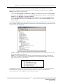
3.7.b Entering Baseline Readings into TECTITE Software When Using the Baseline Feature:
-
When using the Baseline feature, and the TECTITE program to analyze your test data, be sure to enter “0” into
the Pre and Post Test Baseline fields in the Manual Data Entry Table. This is because the Baseline feature
automatically subtracts the measured baseline pressure from the building test pressure readings.
Note: Pressing the CLEAR button clears the baseline measurement buffer and turns the baseline feature off. If the
gauge Mode is changed while the baseline measurement feature is active, the baseline measurement buffer is cleared
and the baseline feature is turned off.
13
Operating Instructions
for the DG700
Chapter 4
Chapter 4
Pressure/Flow @ 50 and @ 25 Modes
Pressure/Flow @ 50 and @ 25 Modes
4.1 Mode Summary
Mode
Application
Channel A Display
Channel B Display
Pressure/Flow @ 50 Pa
(PR/ FL @50)
Specialized mode for
one-point Blower
Door building
airtightness test.
Building pressure in Pascals.
Building leakage at 50 Pascals in units
chosen (CFM@50, m3/h@50, l/s@50,
in2@50, cm2@50).
Pressure/Flow @ 25 Pa
(PR/ FL @25)
Specialized mode for
one-point total
leakage duct
airtightness test.
Duct system pressure in Pascals.
Total duct leakage at 25 Pa in units
chosen (CFM@25, m3/h@25, l/s@25,
in2@25, cm2@25).
Note: Appendix A contains Quick Guides for using the DG-700 to conduct one-point building and duct system
airtightness tests using the @50 and @25 features.
4.2 Overview of Pressure/Flow @ 50 and @ 25 Modes
4.2.a Pressure/Flow @ 50 Mode:
The Pressure/Flow @ 50 mode is used to conduct a one-point
Blower Door building airtightness test. In this mode, Channel A
is used to measure building pressure while Channel B is used to
display estimated building leakage at a test pressure of 50
Pascals. The leakage estimate shown on Channel B is
determined by mathematically adjusting the measured air flow
from the selected Blower Door fan using the real-time Channel A building pressure reading and a Can’t Reach
Pressure factor (see Section 4.8 below).
4.2.b Pressure/Flow @ 25 Mode:
The Pressure/Flow @ 25 mode is a specialized mode used for
conducting a one-point total leakage duct airtightness test. In this
mode, Channel A is used to measure duct system pressure while
Channel B is used to display estimated total duct leakage at a
test pressure of 25 Pascals. The leakage estimate shown on
Channel B is determined by mathematically adjusting the
measured air flow from the selected Duct Blaster fan using the real-time Channel A duct system pressure reading
and a Can’t Reach Pressure factor (see Section 4.8 below).
To select the Pressure/Flow @ 50 or @ 25 modes, press the MODE button until the selected operating
mode shown on the gauge display is PR/ FL @50 or PR/ FL @25. When first entering either of these
two modes, the default pressure units on Channel A is Pascals, the default leakage units on Channel B is
CFM @ 50 or 25, and the default time averaging period is 1 second average.
14
Operating Instructions
for the DG700
Chapter 4
Pressure/Flow @ 50 and @ 25 Modes
4.2.c Benefits of Using the @ 50 and @ 25 Modes:
The @ 50 and @ 25 modes provide four distinct benefits for one-point building and duct airtightness testing:
-
-
The operator no longer needs to waste time adjusting and re-adjusting the fan speed control to achieve a test
pressure of exactly 50 or 25 Pascals – just get close to the target pressure and make your measurement. As long
as the test pressure displayed on Channel A is within 5 Pascals of the 50 or 25 Pascal target pressure, any errors
introduced by estimating the leakage on Channel B will typically be very small (less than 1% - see Tables 4.1
and 4.2 below for more information).
The leakage estimate displayed on Channel B will typically be very stable because of the continuous
adjustments made using the Channel A test pressure.
If you can not achieve the target test pressure of 50 or 25 Pascals because the building or duct system is
extremely leaky, a leakage estimate at the target pressure will automatically be displayed on Channel B.
When in the @ 50 or @ 25 modes, leakage estimates can be displayed as a leakage rate (e.g. CFM @,
m3/hr @, l/s @ ), or as a leakage area (e.g. square inches @ or square centimeters @) to visualize the
physical size of the measured air leaks.
4.3 Changing the Selected Test Device and Configuration
When in the Pressure/Flow @ 50 or @ 25 modes, the following Energy Conservatory test
devices can be selected:
Model 3 (110V) Minneapolis Blower Door™ fans (BD 3).
Model 3 (220V) Minneapolis Blower Door™ fans (BD 3 220).
Model 4 (220V) Minneapolis Blower Door fans (BD 4).
Series A Minneapolis Duct Blaster® fans (DB A).
Series B Minneapolis Duct Blaster® fans (DB B).
Press the DEVICE button to toggle through the available test devices. The currently selected test device is shown in
the Device section of the gauge display.
Once a test device is selected, the configuration of the device (i.e. flow rings, door position or plate installed) can be
selected by pressing the CONFIG button. The currently selected device configuration is shown in the Config section
of the gauge display.
4.4 “-----”or “LO” Displayed on Channel B
Whenever “-----” or “LO” appears on Channel B in the PR/ FL @ 50 or @ 25 modes, the DG-700 can not
calculate a reliable leakage estimate. The messages “-----” and “LO” appear on Channel B under the following
three conditions:
“-----” is continuously displayed when the test pressure from Channel A is below the minimum test pressures
listed below. Estimating leakage results when the test pressure is below these values may result in large errors.
-
10 Pascals when in the @ 50 mode.
5 Pascals when in the @ 25 mode.
“LO” is continuously displayed when there is negligible air flow through the test device.
“LO” alternates with a flow reading when the air flow reading through the device is unreliable (i.e. you are
trying to measure a flow outside of the calibrated range of the test device in its current configuration). If
possible, you should change the test device configuration to match the flow rate being measured (e.g. install a
flow ring or a smaller flow ring).
15
Operating Instructions
for the DG700
Chapter 4
Pressure/Flow @ 50 and @ 25 Modes
4.5 Changing the Leakage Units
When in the Pressure/Flow @ 50 or @ 25 operating modes, the DG-700 can display leakage results on
Channel B in units of CFM@, m3/hr@, l/s@, in2@, and cm2@. The default air flow unit is CFM@.
To change the leakage units for Channel B, press the UNITS button. The selected leakage units are
shown on the gauge display directly below the Channel B readings. The pressure unit for Channel A is always
Pascals when in the Pressure/Flow @ 50 or @ 25 modes.
4.6 Changing the Time Averaging Period
To change the selected time averaging period for both Channel A and B, press the TIME AVG button.
The selected time averaging period is shown in the TIME AVG portion of the gauge display. (See
Section 1.5 for an overview of the time averaging periods.)
4.7 Using the Baseline Pressure Feature in Pressure/Flow Mode
The BASELINE feature on Channel A allows the user to measure and record a
baseline pressure reading, and then display the baseline adjusted pressure reading.
This feature is commonly used during both building and duct airtightness test
procedures where the user wishes to display the actual change in building or duct pressure caused by operation of the
Blower Door or duct airtightness testing fan. In order to accurately determine the change in pressure from the test
fan, the user first needs to know the building or duct system pressure (with reference to outside) prior to the test fan
being turned on. This initial baseline pressure reading can be quickly measured and then used to adjust the test
pressure readings to determine the actual change in pressure caused by operation of the Blower Door or duct
airtightness test fan. (See Sections 1.6, 2.5 and 3.7 for a description and examples on how to use the Baseline
feature.)
4.8 Leakage Estimate Calculations Used in the @ 50 and @ 25 Modes
4.8.a @ 50 Mode:
The following equation is used to estimate leakage rates when in the @ 50 mode:
50
Displayed Leakage Rate
(Channel B)
=
Measured Blower
Door Air Flow Rate
x
0.65
Current Test Pressure (Pa)
(Channel A)
The following equation is used to estimate leakage area when in the @ 50 mode (square inches):
Displayed Leakage Area
(Channel B)
=
Estimated Leakage
Rate
(CFM50)
/
7.495
16
Operating Instructions
for the DG700
Chapter 4
Pressure/Flow @ 50 and @ 25 Modes
The following equation is used to estimate leakage area when in the @ 50 mode (square centimeters):
Displayed Leakage Area
(Channel B)
=
Estimated Leakage
Rate
(CFM50)
/
1.1617
Note: Leakage areas calculated by the DG-700 are Equivalent Orifice Leakage Areas (EOLA), which are defined as
the area of a sharp edged hole that would leak at the same flow rate as the estimated leakage rate, when the hole is
subjected to the target test pressure (e.g. 50 Pa or 25 Pa). The purpose of the EOLA estimate is to provide a simple
physical interpretation of the cumulative size of the leaks measured by the airtightness test. The EOLA estimates are
not appropriate for use in specific infiltration models (such as the LBL or AIM infiltration models) which require
leakage area estimates calculated using different equations and assumptions.
4.8.b @ 25 Mode:
The following equation is used to estimate leakage rates when in the @ 25 mode:
25
Displayed Leakage Rate
(Channel B)
=
Measured Duct
Blaster Air Flow Rate
x
0.60
Current Test Pressure (Pa)
(Channel A)
The following equation is used to estimate leakage area when in the @ 25 mode (square inches):
Displayed Leakage Area
(Channel B)
=
Estimated Leakage
Rate
(CFM25)
/
5.3
The following equation is used to estimate leakage area when in the @ 25 mode (square centimeters):
Displayed Leakage Area
(Channel B)
=
Estimated Leakage
Rate
(CFM25)
/
0.8215
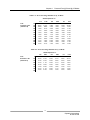
4.8.c Errors in Leakage Estimates:
Tables 4.1 and 4.2 below show the errors in the @ 50 and @ 25 leakage estimates from the following 2 sources:
-
The actual test pressure (Channel A) not being equal to the target pressure (i.e. 50 or 25 Pascals), and
The actual exponent of the leaks being measured differing from the assumed exponent of 0.65 (for @ 50) and
0.60 (for @ 25).
For example, Table 4.1 shows that for a one-point 50 Pa Blower Door building airtightness test, a 2.5% error would
be introduced if the leakage estimate was determined at an actual test pressure of 30 Pa (Channel A), and the actual
exponent of the leaks was 0.60 rather than the assumed value of 0.65.
17
Operating Instructions
for the DG700
Chapter 4
Pressure/Flow @ 50 and @ 25 Modes
Table 4.1: Error in Leakage Estimate for @ 50 Mode
Actual exponent “n”
Test
Pressure in Pa
(Channel A)
10
15
20
25
30
35
40
45
50
55
60
65
0.5
21.4%
16.5%
12.8%
9.9%
7.4%
5.2%
3.3%
1.6%
0.0%
-1.4%
-2.8%
-4.0%
0.55
14.9%
11.3%
8.8%
6.7%
5.0%
3.5%
2.2%
1.0%
0.0%
-1.0%
-1.8%
-2.7%
0.6
7.7%
5.8%
4.5%
3.4%
2.5%
1.8%
1.1%
0.5%
0.0%
-0.5%
-0.9%
-1.3%
0.65
0.0%
0.0%
0.0%
0.0%
0.0%
0.0%
0.0%
0.0%
0.0%
0.0%
0.0%
0.0%
0.7
-8.4%
-6.2%
-4.7%
-3.5%
-2.6%
-1.8%
-1.1%
-0.5%
0.0%
0.5%
0.9%
1.3%
0.75
-17.5%
-12.8%
-9.6%
-7.2%
-5.2%
-3.6%
-2.3%
-1.1%
0.0%
0.9%
1.8%
2.6%
Table 4.2: Error in Leakage Estimate for @ 25 Mode
Actual exponent “n”
Test
Pressure in Pa
(Channel A)
5
10
15
20
25
30
35
40
0.5
14.9%
8.8%
5.0%
2.2%
0.0%
-1.8%
-3.4%
-4.8%
0.55
7.7%
4.5%
2.5%
1.1%
0.0%
-0.9%
-1.7%
-2.4%
0.6
0.0%
0.0%
0.0%
0.0%
0.0%
0.0%
0.0%
0.0%
0.65
-8.4%
-4.7%
-2.6%
-1.1%
0.0%
0.9%
1.7%
2.3%
0.7
-17.5%
-9.6%
-5.2%
-2.3%
0.0%
1.8%
3.3%
4.6%
0.75
-27.3%
-14.7%
-8.0%
-3.4%
0.0%
2.7%
4.9%
6.8%
18
Operating Instructions
for the DG700
Chapter 5
Chapter 5
Pressure/Air Handler Flow Mode
Pressure/Air Handler Flow Mode
5.1 Mode Summary
Mode
Application
Channel A Display
Channel B Display
Pressure/AH Flow
(PR/ AH)
Specialized mode for
measuring air handler
flow rates using a
TrueFlow Air
Handler Flow Meter
or a Duct Blaster fan.
Normal system operating
pressure (NSOP) and test flow
system operating pressure
(TFSOP) in Pascals.
Total air handler flow in units chosen
(CFM, m3/h, l/s). Air flow from the
selected Energy Conservatory test
device is continuously adjusted using
the measured NSOP and TFSOP
readings from Channel A.
Note: Appendix A contains a Quick Guide for using the DG-700 with the Pressure/Air Handler Flow feature.
5.2 Overview of Pressure/Air Handler Flow Mode
The Pressure/Air Handler Flow mode is a specialized mode used to measure air handler flow with a TrueFlow Air
Handler Flow Meter or a Duct Blaster fan. The PR/ AH mode consists of the following 2-step procedure:
Step 1: When first entering the PR/ AH mode, Channel A
is set up to measure a Normal System Operating Pressure
(NSOP) in the duct system, under normal operating
conditions (e.g. existing filter in place, no test device
installed). Pressing the START button initiates a long-term
average NSOP pressure measurement, and pressing ENTER
records and enters the NSOP reading into the gauge.
Step 2: Once the NSOP measurement is made and entered
into the gauge (Step 1), the gauge is set up to simultaneously
measure the Test Flow System Operating Pressure (TFSOP)
on Channel A, and to display the estimated air handler flow
rate on Channel B. The flow rate estimate shown on
Channel B is determined by continuously adjusting the
measured air flow from the selected test device using a flow resistance correction factor calculated from the
NSOP and TFSOP pressure readings.
(Estimated Air Handler Flow = Test Device Flow x Flow Resistance Correction Factor)
Note: TFSOP is the operating pressure in the duct system, at the same location used for the NSOP reading, with
a TrueFlow Metering Plate or Duct Blaster fan installed. TFSOP is referred to in the TrueFlow Operation
Manual as the TrueFlow System Operating Pressure.
To select the Pressure/Air Handler Flow mode, press the MODE button until the selected operating
mode shown on the gauge display is PR/ AH.
5.3 Changing the Selected Test Device and Configuration
When in the Step 2 part of the PR/ AH procedure, press the DEVICE button to select the
test device being used to measure air handler flow. When using the PR/ AH mode, the
TrueFlow Metering Plates (TF) and the Duct Blaster fans (DB A or DB B) are the only
compatible test devices.
19
Operating Instructions
for the DG700
Chapter 5
Pressure/Air Handler Flow Mode
Once a test device is selected, the configuration of the device (i.e. flow rings, or plate installed) can be selected by
pressing the CONFIG button. The currently selected device configuration is shown in the Config section of the
gauge display.
5.4 “-----”or “LO” Displayed on Channel B
Whenever “-----” or “LO” appears on Channel B in the Step 2 part of the PR/ AH procedure, the DG-700 can not
display a reliable air handler flow estimate. The messages “-----” and “LO” appear on Channel B under the
following three conditions:
“-----” is continuously displayed when either the recorded NSOP reading, or the current TFSOP reading is
below 2 Pa.
“LO” is continuously displayed when there is negligible air flow through the test device.
“LO” alternates with a flow reading when the air flow reading through the device is unreliable (i.e. you are
trying to measure a flow outside of the calibrated range of the test device in its current configuration). If
possible, you should change the test device configuration to match the flow rate being measured (e.g. if using a
Duct Blaster fan, install a flow ring or a smaller flow ring).
5.5 Changing the Air Handler Flow Units
When in the PR/ AH mode, the DG-700 can display air handler flow on Channel B in units of CFM,
m3/hr, and l/s. The default air flow unit is CFM. To change the flow units for Channel B, press the
UNITS button while in the Step 2 part of the procedure. The selected flow units are shown on the gauge
display directly below the Channel B readings. The pressure unit for Channel A is always Pascals when in the
PR/ AH mode.
5.6 Changing the Time Averaging Period for the Step 2 Procedure
To change the selected time averaging period for the Step 2 part of the PR/ AH procedure, press the
TIME AVG button. The selected time averaging period is shown in the TIME AVG portion of the
gauge display. (See Section 1.5 for an overview of the time averaging periods.) During the Step 1 part of
the procedure, the time average feature is always set to long-term average.
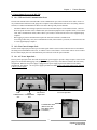
5.7 Test Procedure For Measuring Air Handler Flow
5.7.a Step 1: Measuring the NSOP
-
Open a window or door between the building and outside to prevent pressure changes in the building during the
test. If the air handler fan is installed in an unconditioned zone (e.g. crawlspace, attic), open any vents or access
doors connecting that zone to the outside (or to the building) to prevent pressure changes in the zone during the
test.
-
Make sure all supply and return registers are open and untapped. Replace filters if they are dirty (or keep dirty
filters in place if you want to measure flow in a "as found" condition). Turn on the air handler.
20
Operating Instructions
for the DG700
Chapter 5
Pressure/Air Handler Flow Mode
-
Insert a static pressure probe into the supply plenum, or in a main supply trunk line a few feet away from the
supply plenum. Make sure the static pressure probe is pointing into the air flow created by the air handler fan.
-
Connect a piece of tubing to the static pressure probe. Connect the other end of the tubing to the Channel A
Input tap on the DG-700. The Channel A Reference tap should be connected to the inside of the building, or it
can be connected to an unconditioned zone containing the air handler provided that the zone remains at the same
pressure as the building during the test.
-
Turn on the gauge and put it the PR/ AH mode by pressing the MODE button. The icon “NSOP” will begin to
flash in the Channel A display, indicating that the PR/ AH measurement feature has been initiated. At this
point, the gauge is monitoring the real-time Channel A NSOP pressure, but is not recording the reading. The
Channel B display is not active at this time.
-
Press the START button to begin the NSOP measurement
procedure on Channel A. Once the START button is
pressed, the icon “NSOP” stops flashing and the gauge
begins recording a long term average NSOP pressure
reading on Channel A. During the measurement procedure,
the Channel B display is used as a timer to let the user
know how long (in seconds) the NSOP measurement has been active. The longer the measurement time,
generally the more stable the reading typically becomes. In the screen to the right, the measured NSOP pressure
is 56.7 Pascals (measured over the past 30 seconds).
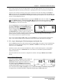
-
Once you are satisfied with the NSOP reading, press the ENTER key to accept and enter the reading into the
gauge. Turn off the air handler, and leave the static pressure probe in place and connected to the gauge.
5.7.b Step 2: Measuring the TFSOP and Adjusted Air Handler Flow
-
Once the NSOP measurement is made and entered into the gauge (Step 1), the gauge is set up to simultaneously
measure the Test Flow System Operating Pressure (TFSOP) on Channel A, and to display the estimated air
handler flow rate on Channel B.
-
Install the test device used to measure air handler flow (either a TrueFlow Metering Plate, or a Duct Blaster
Fan). Connect the test device to Channel B. Refer to the TrueFlow or Duct Blaster operation manuals for
installation instructions.
-
Select the installed test device and device configuration on the DG-700 using the DEVICE and CONFIG
buttons.
If Using a TrueFlow Metering Plate
-
Turn on the air handler. Channel A will now display the
TFSOP reading from the static pressure probe, and
Channel B will display adjusted air handler flow. The flow
rate estimate shown on Channel B is determined by
continuously adjusting the measured air flow from the
TrueFlow Metering Plate using a flow resistance correction
factor calculated from the NSOP and TFSOP pressure readings. If the readings are fluctuating, change the time
averaging setting to 5 second, 10 second, or long-term average using the TIME AVG button.
21
Operating Instructions
for the DG700
Chapter 5
Pressure/Air Handler Flow Mode
If Using a Duct Blaster Fan (Pressure Matching Method)
-
Turn on the air handler. Now turn on and adjust the Duct
Blaster fan (along with the air handler fan) so that the
TFSOP reading on Channel A is close (within 5 Pa) to the
NSOP reading entered into the gauge in Step 1. There is
no need to exactly match the NSOP and TFSOP pressures,
because the gauge is making an adjustment to the measured
Duct Blaster fan flow using a flow resistance correction factor calculated from the NSOP and TFSOP pressure
readings. If the readings are fluctuating, change the time averaging setting to 5 second, 10 second, or long-term
average using the TIME AVG button.
Note: If you are unable to get the TFSOP to within 5 Pascals of the NSOP reading, the gauge will continue to
display an adjusted air handler flow rate using the calculated flow resistance correction factor. The greater the
difference between the NSOP and TFSOP readings, the higher the probability that the flow resistance
correction factor will introduce errors into the flow estimate.
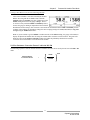
5.8 Flow Resistance Correction Factors Used in the DG-700
The following equation is used to calculate the flow resistance correction factor used by the DG-700 in the PR/ AH
mode:
NSOP
Flow Resistance
Correction Factor
=
0.50
TFSOP
22
Operating Instructions
for the DG700
Chapter 6
Chapter 6
Pressure/Velocity Mode
Pressure/Velocity Mode
6.1 Mode Summary
Mode
Application
Channel A Display
Channel B Display
Pressure/Velocity
(PR/ V)
Multi-purpose pressure
and air velocity
measurements.
Pressure in Pascals.
Air velocity in units chosen
(FPM, m/s).
6.2 Overview of Pressure/Velocity Mode
The Pressure/Velocity mode is a multi-purpose mode used to
measure a pressure signal on Channel A and/or measure an air
velocity reading from a pitot tube connected to Channel B.
To select the Pressure/Velocity mode, press the
MODE button until the selected operating mode
shown on the gauge display is PR/ V. When first entering this mode, the default air velocity unit on
Channel B is feet per minute (FPM). Channel A always displays pressure readings in Pascals when in the PR/ V
mode.
6.3 Changing the Air Velocity Units
When in the PR/ V operating mode, the DG-700 can display air velocity readings on Channel B in
units of feet per minute or meters per second. To change the air velocity units for Channel B, press
the UNITS button. The selected units are shown on the Channel B display directly below the channel
reading.
6.4 Changing the Time Averaging Period
To change the selected time averaging period for both Channel A and B, press the TIME AVG button.
The selected time averaging period is shown in the TIME AVG portion of the gauge display. (See
Section 1.5 above for a complete description of the time averaging periods.)
6.5 Air Velocity Calculations Used in the DG-700
The following equations are used to calculate air velocity from a pitot tube connected to Channel B. Note: The
pitot tube should be set up to measure velocity pressure in order for the DG-700 to correctly display air velocity
readings.
Air Velocity
(feet/minute)
= 1096.2
Velocity
Pressure (in. wc)
0.075 (lb/ft3)
0.50
Air Velocity
(meters/second)
= 1.4142
Velocity
Pressure (Pa)
0.50
1.204 (Kg/m3)
23
Operating Instructions
for the DG700
Chapter 7
Chapter 7
Servicing and Maintenance
Servicing and Maintenance
7.1 Gauge Calibration and Servicing
7.1.a Calibration:
The DG-700 is calibrated at our factory prior to being shipped. A sticker on the back of the gauge case will indicate
the date of calibration, as well as the next recommended recalibration date. Under normal operation, we recommend
that the gauge be recalibrated once every two years. Gauge recalibration is a service provided by The Energy
Conservatory for a small fee ($80 as of 7/1/13). Gauges needing recalibration should be sent to:
The Energy Conservatory
2801 21st Ave. S., Suite 160
Minneapolis, MN 55407
Attn: Digital Gauge Recalibration
When returning a gauge for calibration, please print out the Equipment Return Form from our website
(www.energyconservatory.com/sites/default/files/documents/equipment_return_form.pdf), fill it out completely, and
include a copy of the completed form along with the equipment being returned.
7.1.b Servicing/Repairs:
All factory authorized repairs for the DG-700 gauge are conducted at the above address. To have your gauge
repaired, send the gauge to the above address along with a completed copy of our Equipment Return Form (see
above).
7.2 Low Battery Indicator/Battery Replacement
The DG-700 is powered by 6 AA batteries located in the battery compartment on the back of the gauge. We
recommend that Alkaline or rechargeable batteries (e.g. nickel-metal hydride or NiCd) be used with this gauge.
Whenever the gauge is turned on, the battery voltage is measured and temporarily displayed in the Channel B
display area.
7.2.a Low Battery Indicators:
A low battery icon “BAT” begins to blink on the gauge display when it is time to replace (or recharge) the batteries.
The BAT icon is set to appear when the measured battery voltage drops below 6.0 volts. The gauge will continue to
provide reliable operation for a short time following appearance of the BAT icon. Once the batteries have discharged
to a level which prohibits reliable operation, the words “LO BAT” appear in the Channel A and B display areas, and
the gauge will no longer function. Fully charged batteries will typically provide 4-5 days of continuous operation
before the BAT icon appears on the gauge display.
7.2.b Battery Replacement:
To remove the existing batteries from the battery compartment, first turn off the gauge, and then remove the battery
compartment cover plate by sliding it away from the gauge. Carefully remove each battery from the battery
compartment.
Carefully replace the 6 AA batteries. Be sure to insert the batteries with the proper polarity (+/-) as illustrated on the
inside of the battery compartment. Replace the battery compartment cover.
24
Operating Instructions
for the DG700
Chapter 7
Servicing and Maintenance
7.3 Troubleshooting/Resetting the DG-700
If the DG-700 gauge locks up or otherwise appears to be displaying inconsistent readings, try the following steps to
reset the gauge.
Simply turn the gauge off for 5 seconds and then turn it back on (using the ON/OFF button).
If turning the gauge off and on does not take care of the problem (or you were unable to turn the gauge off), first
remove the batteries from the battery compartment. Once the batteries have been removed, hold down the
ON/OFF button for 10 seconds to fully discharge the gauge’s internal electronic components. Carefully replace
the 6 AA batteries. Be sure to insert the batteries with the proper polarity (+/-) as illustrated on the inside of the
battery compartment. Turn the gauge back on.
If neither of the steps above takes care of the problem, you will need to send the gauge back to The Energy
Conservatory for servicing (see Section 7.1.b above).
7.4 AC Power Supply Specifications
The AC power input jack can be used with an optional AC power supply to provide a long term power source for the
gauge (to be used when data logging). The gauge is normally powered by 6 AA batteries located in the rear battery
compartment. When the AC power supply is plugged in, the power supply bypasses the batteries in the battery
compartment. Note: Always turn off the gauge before plugging in the AC power supply.
Universal Specifications for Power Supply: 100-240V/50/60Hz Input, 12VDC Output, Center “+”, 12mm Barrel
Length, 3 W Min. Output (International mains adapters included).
25
Operating Instructions
for the DG700
Appendix A
Appendix A
Quick Guides for Using the DG-700 with Energy Conservatory Test Devices
Quick Guides for Using the DG-700 with Energy
Conservatory Test Devices
A.1 One-Point 50 Pascal Building Depressurization Test using the Model 3 Minneapolis Blower
Door™ and DG-700 Digital Gauge
1.
Install the Blower Door system.
a) Install the aluminum frame and nylon panel in an exterior doorway of a large open room.
b) Attach the gauge mounting board and fan speed controller to a door, or to the aluminum frame gauge hanger bar,
using the C-clamp on the back of the
mounting board.
c) Secure the DG-700 gauge onto the
mounting board (using the Velcro strips) and
connect tubing to the DG-700 as shown in the
illustration to the right.
Connect the Red
d) Run approximately 3 - 5 feet of the
tubing to the
Channel B Input
remaining end of the Green tubing outside
tap. The other
Leave
tap
open.
through one of the patches in the bottom
end of the tubing
corners of the nylon panel. Be sure the
should be
connected to the
outside end of the tubing is well away from
Blower Door fan.
Connect the Green tubing to
the exhaust flow of the Blower Door fan and
the Channel A Reference tap.
is protected from the wind.
The other end of the tubing
Leave tap open.
should be run to the outside.
e) Install the Blower Door fan, with the
Flow Rings and No-Flow Plate attached, into
the large hole in the nylon panel. The exhaust
side of the fan should be outside, and the inlet side of the fan (the side with the Flow Rings) should be inside the
building.
f) Insert the female plug from the fan speed controller into the receptacle located on the fan electrical box. The
remaining cord (power cord) should be plugged into a power outlet that is compatible with the voltage/frequency of
the fan motor and speed controller.
g) If your fan has a direction switch, be sure it is set to blow air out of the building.
h) The remaining end of the Red tubing should now be connected to the pressure tap on the Blower Door fan
electrical box.
i) If your DG-700 gauge and fan speed control are compatible for Cruise Control, install the fan control cable into
the 3.5 mm communication jacks located on the top of the DG-700 and on the side of the speed controller (otherwise
skip this step).
2.
Prepare the building for the Test.
a) Close all exterior doors and windows, and open all interior doors. Because few house basements can be
completely sealed from the house and usually some conditioning of the basement is desirable, they are typically
included as conditioned space.
b) Adjust all combustion appliances so that they do not turn on during the test.
c) Be sure all fires are out in fireplaces and woodstoves. Close all fireplace and wood stove doors to prevent
scattering of ashes.
d) Turn off any exhaust fans, vented dryers, and room air conditioners.
3.
Conducting the Test.
a) Turn on the DG-700 by pressing the ON/OFF button.
b) Press the MODE button twice to put the gauge into the PR/ FL @50 Mode. In this Mode, Channel A is used to
measure building pressure while Channel B is used to display the estimated building leakage at a test pressure of 50
Pascals. (The leakage estimate shown on Channel B is determined by mathematically adjusting the actual air flow
from the Blower Door fan using the Channel A building pressure reading and a Can’t Reach Pressure factor.)
26
Operating Instructions
for the DG700
Appendix A
Quick Guides for Using the DG-700 with Energy Conservatory Test Devices
c) With the fan inlet still covered press the BASELINE button to initiate the building baseline measurement
procedure on Channel A. Press START to begin the baseline measurement. During a baseline measurement,
Channel A will display a long-term average baseline pressure reading while Channel B is used as a timer in seconds
to show the elapsed measurement time. When you are satisfied with the baseline measurement, press the ENTER
button to accept and enter the baseline reading into the gauge. The
Fan Configuration
Flow Range (cfm)
Channel A display will now show an ADJ icon to indicate that it
for Model 3 Fan
is displaying a baseline adjusted building pressure value.
Open
(no
Flow
Ring)
6,300 - 2,435
d) Remove the No-Flow Plate from the Blower Door fan and
Ring A
2,800 - 915
install the Flow Ring which you think best matches the needed fan
Ring B
1,100 - 300
flow (see Table to the right).
Ring C
330 85
e) Check (and adjust if necessary) the selected test Device (i.e.
fan) and Configuration (i.e. Flow Ring) shown in the upper part of the gauge display to match the fan and Flow Ring
being used in the test. For example, the Device icon for the Model 3 (110V) Blower Door fan is BD 3, and the
Configuration icon for Ring A is A1. Press the DEVICE button to change the selected fan. Press the CONFIG
button to change the selected Flow Ring.
f)
Turn on the Blower Door fan.
If Using Cruise Control:
Turn the Blower Door speed control knob to the “just on” position (i.e. from the off position, turn the
controller knob clockwise only until you feel the click and no farther, the fan will not be turning). Now
press the Begin Cruise (Enter) button. The Channel A display will now show the number 50 (your target
Cruise pressure). Press the Start Fan (Start) button. The Blower Door fan will now slowly increase speed
until the building depressurization displayed on Channel A is approximately -50 Pascals.
If Manually Controlling Fan:
Turn on the Blower Door fan by slowly turning the fan controller clockwise. As the fan speed increases, the
building depressurization displayed on Channel A should also increase. Continue to increase the fan speed
until the building depressurization shown on Channel A is between –45 and –55 Pascals. Do not waste time
adjusting and re-adjusting the fan speed control to achieve a test pressure of exactly –50 Pascals.
g) Channel B will now display the One-Point 50 Pascal leakage estimate. Record this number. If the leakage
estimate is fluctuating more than desired, try changing the Time Averaging setting on the gauge by pressing the
TIME AVG button and choosing the 5 or 10 second or Long-term averaging period. (If “------“ or “LO” appear on
Channel B, see #4 below).
h) Turn off the Blower Door fan. If you are using Cruise Control, this is done by pressing the Stop Fan (Clear)
button).
4.
“-----” or “LO” appearing on Channel B
Whenever “-----” or “LO” appears on Channel B in the PR/ FL @ 50 Mode, the DG-700 can not calculate a reliable
leakage estimate. The messages “-----” and “LO” appear on Channel B under the following three conditions:
a) “-----” is continuously displayed when the building test pressure from Channel A is below a minimum value of
10 Pascals. Estimating building leakage results when the test pressure is below this value may result in large errors. If
possible, install a larger Flow Ring or remove the Flow Rings to generate more fan flow.
b) “LO” is continuously displayed when there is negligible air flow through the test device.
c) “LO” alternates with a flow reading when the air flow reading through the device is unreliable (i.e. you are
trying to measure a flow outside of the calibrated range of the test device in its current configuration). If possible, you
should change the test device configuration to match the flow rate being measured (e.g. install a Flow Ring or a
smaller Flow Ring). Be sure the fan is off when changing Flow Rings.
Note: If you change the Flow Rings on the fan, be sure to change the Configuration setting on the gauge to match the
installed Ring.
27
Operating Instructions
for the DG700
Appendix A
Quick Guides for Using the DG-700 with Energy Conservatory Test Devices
A.2 One-Point 25 Pascal Total Leakage Duct Pressurization Test Using the Series B Minneapolis
Duct Blaster and DG-700 Digital Gauge
1.
Connect the Duct Blaster fan to the duct system.
a) Choose a location to install the Duct Blaster fan. In single, double or triple returned systems, the largest and
closest return to the air handler is usually the best choice. Note: In multi-return systems (a return in every room),
installing at the air handler cabinet is often best.
b) Remove any remote filters from the chosen return and then connect the black square transition piece to the return
using temporary tape. Completely seal the remaining open area of the return with tape.
c) Pull the Duct Blaster fan and flex duct out of the carrying case. Connect the flex duct to the exhaust side of the
fan (i.e. the side with the metal guard) using the round transition piece and connect trim. Connect the open end of the
flex duct to the square transition piece using the velcro strap on
Fan Configuration
Flow Range (cfm)
the flex duct.
For Series B Duct Blaster
d) Connect the fan speed controller to the fan and plug it into a
Open (no Flow Ring)
1,500 - 600
grounded power outlet.
Ring 1
800 – 225
e) Install the Flow Ring which you think best matches the
Ring 2
300 – 90
needed fan flow.
Ring 3
125 – 10
f) If your DG-700 gauge and fan speed controller are
compatible with Cruise Control, install the fan control cable into the 3.5 mm communication jacks located on top of
the DG-700 and on the side of the speed controller (otherwise skip this step).
2.
Prepare the duct system and house for the Test.
a) Adjust the HVAC system controls so that the air handler does not turn on during the Test.
b) Temporarily seal off all remaining supply and return registers, and combustion or ventilation air inlets which are
connected to the duct system. Use Duct Mask temporary register sealing material provided with your Duct Blaster,
or use painters tape and paper.
c) Turn off any exhaust fans, vented dryers, and room air conditioners.
d) Remove all central filters (i.e. in air handler or return plenum).
e) Open a door or window between the house and outside to prevent changes in house pressure when the Duct
Blaster is running.
f) If the Duct Blaster is installed in an attic, garage or crawlspace - open vents or access panels or doors from these
spaces to the outside.
3.
Connect tubing to DG-700 Pressure Gauge.
a) Select a location to measure duct
pressure. The best location for measuring duct
pressure is often in the supply trunkline or
plenum. Drill a small hole (1/4" to 3/8" OD)
into the duct to allow a static pressure probe to
be installed. Install the static pressure probe
with the end of the probe pointing into the air
flow from the Duct Blaster fan. If the duct
system is reasonably airtight (e.g. less than
200 cfm25 of leakage), duct pressures can be
measured at any supply register by inserting
the end of the tubing through the temporary
register seal.
b) Connect tubing to the DG-700 as shown
in the illustration to the right.
4.
To Duct System
(insert into register
or connect to static
pressure probe)
Connect to inside of house (if
gauge is installed in the house,
leave this tap open). Be sure
window is open.
To Duct Blaster Fan
(brass tap in middle
of fan housing)
Connect to space where
fan is installed (if fan and
gauge are in the same
space, leave open).
Conducting the Test.
a) Turn on the gauge by pressing the ON/OFF button.
b) Press the MODE button three times to put the guage into the PR/ FL @25 Mode. In this Mode, Channel A is
used to measure duct system pressure while Channel B is used to display estimated duct leakage at a test pressure of
25 Pascals. (The leakage estimate shown on Channel B is determined by mathematically adjusting the actual air flow
from the Duct Blaster fan using the Channel A duct system pressure reading and a Can’t Reach Pressure factor.)
28
Operating Instructions
for the DG700
Appendix A
Quick Guides for Using the DG-700 with Energy Conservatory Test Devices
c) Check (and adjust if necessary) the selected test Device (i.e. fan) and Configuration (i.e. Flow Ring) shown in
the upper part of the gauge display to match the fan and Flow Ring being used in the test. For example, the Device
icon for the Series B Duct Blaster fan is DB B, and the Configuration icon for Ring 2 is B2. Press the DEVICE
button to change the selected fan. Press the CONFIG button to change the selected Flow Ring.
d)
Turn on the Duct Blaster fan.
If Using Cruise Control:
Turn the Duct Blaster speed controller to the “just on” position (i.e. turn the controller knob all the way down
counter-clockwise and flip the on/off switch to “ON” – the fan will not be turning). Now press the Begin Cruise
(Enter) button. The Channel A display will now show the number 25 (your target Cruise pressure). Press the
Start Fan (Start) button. The Duct Blaster fan will now slowly increase speed until the duct pressurization
displayed on Channel A is approximately 25 Pascals.
If Manually Controlling Fan:
Turn on the Duct Blaster fan controller and slowly turn the fan controller knob clockwise. As the fan speed
increases, the duct pressurization displayed on Channel A should also increase. Continue to increase the fan
speed until the duct pressurization shown on Channel A is between 20 and 30 Pascals. Do not waste time
adjusting and re-adjusting the fan speed control to achieve a test pressure of exactly 25 Pascals.
e) Channel B will now display the One-Point 25 Pascal Total Duct Leakage estimate. If the leakage estimate is
fluctuating more than desired, try changing the Time Averaging setting on the gauge by pressing the TIME AVG
button and choosing the 5 or 10 second or Long-term averaging period. (If “------“ or “LO” appear on Channel B,
see #5 below).
5.
“-----” or “LO” appearing on Channel B
Whenever “-----” or “LO” appears on Channel B in the PR/ FL @ 25 Mode, the DG-700 can not calculate a reliable
leakage estimate. The messages “-----” and “LO” appear on Channel B under the following three conditions:
a) “-----” is continuously displayed when the duct test pressure from Channel A is below a minimum value of 5
Pascals. Estimating duct leakage results when the test pressure is below this value may result in large errors. If
possible, install a larger Flow Ring or remove the Flow Rings to generate more fan flow.
b) “LO” is continuously displayed when there is negligible air flow through the test device.
c) “LO” alternates with a flow reading when the air flow reading through the device is unreliable (i.e. you are
trying to measure a flow outside of the calibrated range of the test device in its current configuration). If possible, you
should change the test device configuration to match the flow rate being measured (e.g. install a Flow Ring or a
smaller Flow Ring). Be sure the fan is off when changing Flow Rings.
Note: If you change the Flow Ring on the fan, be sure to change the Configuration setting on the gauge to match the
installed Ring.
29
Operating Instructions
for the DG700
Appendix A
Quick Guides for Using the DG-700 with Energy Conservatory Test Devices
A.3 Using the TrueFlow Air Handler Flow Meter and the DG-700 Digital Gauge
1.
Measure the Normal System Operating Pressure (NSOP) with the existing filter in place.
a) Locate the air handler system filter and replace if it is dirty.
b) Install a static pressure probe into the ductwork at one of the 3 locations listed below:
•
•
•
Insert the static pressure probe into the side surface of the supply plenum. The side of the supply plenum
chosen should not have a trunk line, distribution duct or supply register connected to it. The static pressure
probe should point into the airstream.
Or, insert the tip of the static pressure probe into a "dead-end" corner of the supply plenum. A "dead-end"
corner is a corner of the plenum that does not have a trunk line connection, distribution duct connection or
supply register within 8 inches of the corner.
Or, insert the static pressure probe in the side surface of the return plenum. The side of the return plenum
chosen should not have a trunk line, return duct or return register connected to it. The location chosen
should also be at least 24 inches upstream from the TrueFlow Metering Plate, and at least 24 inches
downstream from any 90 degree corners or return trunk line connections. The static pressure probe should
point into the airstream. Note: if the Metering Plate will be installed at a remote filter grille, the static
pressure probe may not be installed in the return plenum (i.e. install it in the supply plenum).
c) Connect a piece of tubing between the static pressure probe and the Channel A Input tap. If the gauge is in the
house during the test procedure, leave the Reference tap on Channel A open. If the gauge is not in the house during
the test procedure (e.g. attic, crawlspace), run additional tubing from the Channel A Reference tap to inside the
house.
d) Turn on the air handler fan to the desired speed. Now turn on the gauge and put it the PR/ AH mode by pressing
the MODE button 4 times. The icon “NSOP” will begin to flash in the Channel A display. At this point, the gauge is
monitoring the real-time Channel A NSOP pressure, but is not recording the reading. The Channel B display is not
active at this time.
e) Press the START button to begin the NSOP measurement
procedure on Channel A. Once the START button is pressed, the
NSOP icon stops flashing and the gauge begins recording a long
term average NSOP pressure reading on Channel A. During the
measurement procedure, the Channel B display is used as a timer to
let the user know how long (in seconds) the NSOP measurement has
been active. The longer the measurement time, generally the more
stable the reading typically becomes. In the screen to the right, the measured NSOP pressure is 56.7 Pascals
(measured over the past 30 seconds).
f) Once you are satisfied with the NSOP reading, press the ENTER key to accept and enter the reading into the
gauge. Turn off the air handler fan, and leave the static pressure probe in place and connected to the gauge on
Channel A.
2.
Install the TrueFlow Metering Plate in an Existing Filter Slot.
a) Remove the existing filter and set it aside.
b) Choose and assemble the metering plate and spacers needed to match the filter slot size.
Filter Slot
(in. x in.)
Flow Metering Plate
14 x 20
14 x 25
16 x 20
16 x 24
16 x 25
18 x 20
20 x 20
20 x 22
20 x 24
20 x 25
20 x 30
24 x 24
#14
#14
#14
#14
#14
#14
#20
#20
#20
#20
#20
#20
Spacer Dimension
(in. x in.)
Spacer 1
Spacer 2
-----5 x 14
2 x 20
2 x 20
2 x 20
4 x 20
-----2 x 20
4 x 20
5 x 20
10 x 20
4 x 20
---------------4 x 16
5 x16
------------------------------4 x 24
30
Operating Instructions
for the DG700
Appendix A
Quick Guides for Using the DG-700 with Energy Conservatory Test Devices
c) Install the assembled metering plate into the filter slot. Be sure the front side of the metering plate is facing into
the air flow (front side has two diamond shaped labels on it). The H-channel gasket should provide a seal around the
metering plate - all of the air flow should pass through the metering plate and not around it. Be sure that the ends of
the flexible tubing connections attached to the plate's pressure sensing grids remain out of the filter slot. Occasionally,
drilling holes into the ductwork may be required as a pathway for the ends of the flexible tubing. The flexible tubing
can be passed through one of the plate's metering holes if this helps in getting the tubing ends outside of the filter
slot.
•
•
•
Obstructions within 6 inches upstream or 2 inches downstream of the metering plate that are blocking air
flow through any of the metering holes may reduce the accuracy of the device.
If there is an obstruction and there is a spacer attached to the metering plate, try to install the metering plate
so that the spacer is directly in front of the obstruction (this will minimize the effect of the obstruction on
the flow measurement).
If the metering plate is installed directly downstream of a 90 degree bend in the duct system, and there is a
spacer attached to the plate, install the metering plate so that the spacer is on the inside corner of the bend
(see diagram to right).
d) Close the filter access opening. Be careful not to pinch off the flexible tubing connections. Temporarily seal
around the filter slot cover with masking tape to prevent air leakage. Note: If you are installing the metering plate at
the filter grille of a single return duct system, simply push the plate into the empty filter rack. Make sure that the front
of the metering plate is facing out (into the air flow). Keep the filter grille door open for the remainder of the test.
3.
Connect the Metering Plate to the DG-700.
a) Connect the tubing from the installed metering plate to the DG-700. Connect the Red ("total pressure grid")
tubing connection to the Channel B Input pressure tap. Connect the Green ("static pressure grid") tubing connection
to the Channel B Reference pressure tap. The Channel A Input tap should remain connected to the static pressure
probe.
4.
Measure the TrueFlow System Operating Pressure (TFSOP) and Adjusted Total Air Handler Flow.
a) Check and adjust if necessary the selected test Device and Configuration shown in the upper part of the gauge
display to match the metering plate installed in Step 2 above. When using the TrueFlow Metering Plates, the Device
icon should always be set to TF, and the Configuration icon should be set to 14 or 20 depending on which metering
plate is installed. Changes to the selected Device and Configuration are made by pressing the DEVICE and
CONFIG buttons.
b) Turn the air handler fan back on to the same speed as used in
Step 1 above. Channel A will now display the TFSOP reading
from the static pressure probe, and Channel B will display
adjusted air handler flow. The static pressure probe should be in
exactly the same position as it was in Step 1 above. The air
handler flow rate estimate shown on Channel B is determined by
continuously adjusting the measured air flow from the TrueFlow
Metering Plate using a flow resistance correction factor calculated from the NSOP and TFSOP pressure readings. If
the readings are fluctuating, change the time averaging setting to 5 second, 10 second, or Long-Term average using
the TIME AVG button.
c) Record the adjusted air flow reading from Channel B. In the screen to the right, the adjusted air flow reading is
1,566 CFM. This result is the estimated air flow at the measurement location with the existing filter in place. Turn off
the air handler fan.
Note: When the TrueFlow Air Handler Flow Meter is installed at a remote filter grille, it is possible to make a
correction to the measured flow through the metering plate which increases the accuracy of the flow measurement.
See Appendix C of the TrueFlow manual for more details.
31
Operating Instructions
for the DG700
Appendix A
Quick Guides for Using the DG-700 with Energy Conservatory Test Devices
A.4 DG-700 Connections Needed to Conduct Automated Blower Door Tests
In order to perform fully automated Blower Door tests using a DG-700, you will need the following components:
•
A fan control cable to connect the fan control output jack on the DG-700 to the communication jack on the side of the
Blower Door fan speed controller. Note: If your Blower Door speed controller does not have a communication jack
on the side of the controller box, you will need to purchase a new speed controller.
•
A communication cable (either USB (A-mini B), or 9-pin serial) to connect the DG-700 to your laptop computer.
•
TECTITE (3.0 or higher) software CD.
Connection Instructions.
1.
Install the TECTITE software onto your computer. Once the software is installed, run the TECTITE program and
access the TECTITE Operation Manual directly from the program’s Help Menu. Refer to this manual on how to
operate the TECTITE software.
2.
Install the Blower Door system as described in the Blower Door operation manual.
3.
Connect the DG-700 to your computer using either a USB cable or a 9-pin serial communication cable.
•
If using a USB cable, follow these instructions:
–
–
–
•
Insert the installation CD labeled “USB Drivers for DG-500 and DG-700 Digital Pressure Gauges” into a CD
drive on your computer (this CD should have been provided with all DG-700 gauges equipped with a USB
Communication Port). Your computer should automatically run the file “autoinstall.bat” from the CD which will
install the necessary USB drivers onto your computer.
Once the USB drivers are installed, plug the “A” (larger) end of the USB communication cable into an open
USB port on your computer. Plug the “mini B” (smaller) end of the cable into the USB Communication Port on
top of the DG-700.
The computer operating system should locate the DG-700 gauge and perform the necessary setup on your
computer.
If using a 9 pin serial cable, plug the male end of the cable into the serial communication port on the top of the
gauge, and the female end of the cable should be plugged into an open serial communication port on your computer.
USB
Communication
Port
Serial
Communication
Port
Fan Control
Output Jack
32
Operating Instructions
for the DG700
Appendix A
•
Quick Guides for Using the DG-700 with Energy Conservatory Test Devices
To check if the USB communication drivers have been properly installed on your computer, or to see if your
computer has an available serial communication port for a 9 pin serial cable, you will need to access the Device
Manager in your Windows operating system.
–
–
To access the Device Manager in Windows XP or 2000, click on Start, then right-click on the My Computer
shortcut and select Properties. This will cause the System Properties window to appear. To open the Device
Manager, click on Hardware and then Device Manager.
To access the Device Manager in Windows Vista, click on Start, then right-click on the Computer shortcut
and select Properties. This will cause the System window to appear. To open the Device Manager, click on
Device Manager.
From the Device Manager window, open the Ports icon to show which communication ports are currently installed
on your computer. In the case illustrated below, the computer has 3 installed communication ports which can be used
to interface with a TEC digital gauge.
–
–
COM1 and COM2 are existing serial communication ports which can be used to communicate with a DG-700
gauge using a standard 9 pin serial cable.
COM3 is a custom communication port created by successfully installing the USB drivers for the DG-700
gauge. (Note: In order for a custom device communication port to be listed under the Ports icon, the DG-700
gauge must be connected to your computer.)
If no COM ports are listed (or a Ports icon does not exist), then either the computer does not have installed serial
communication ports, you have not properly installed the USB drivers to create a custom USB Device
communication port, or a DG-700 gauge is not connected to the computer.
33
Operating Instructions
for the DG700
Appendix A
4.
Quick Guides for Using the DG-700 with Energy Conservatory Test Devices
Connect the DG-700 to the Blower Door fan speed controller using the fan control cable. Plug one end of the cable
into the 3.5 mm fan control output jack on the top of the DG-700, and plug the other end of the cable into the
communication jack on the side of the fan speed controller box.
Fan
Control
Cable
Communication Jack
(Blower Door Speed
Controller)
5.
Connect tubing between the DG-700 and the Blower Door system (tubing connections are detailed in the Blower
Door operation manual).
To inside of building
(leave open if gauge is
in the building)
To BD fan
(red tubing)
A
B
To space upstream of fan inlet.
(If fan inlet and gauge are in the
same space, leave open)
To outside (green
tubing)
6.
Now turn on the Blower Door fan speed controller to the “just on” position (the fan should not be turning in this
position). The speed control knob should be turned all the way down, without being clicked into the “off” position.
7.
Turn on the DG-700 gauge.
8.
Refer to the TECTITE and Blower Door manuals for instructions on how to conduct the Blower Door test.
34
Operating Instructions
for the DG700
Appendix A
Quick Guides for Using the DG-700 with Energy Conservatory Test Devices
Communication Cable
(USB or 9 pin Serial) To
Computer
Building Pressure
Green Hose
(A Reference)
Fan Pressure
Red Hose
(B Input)
Fan Control
Cable
Fan Power
Cord
To Power Source
35
Operating Instructions
for the DG700
Appendix A
Quick Guides for Using the DG-700 with Energy Conservatory Test Devices
A.5 Using the DG-700’s Cruise Control Feature
All new DG-700 gauges include a Cruise Control feature which allows you to automatically control Minneapolis Blower
Door and Duct Blaster fans to maintain a constant building or duct pressure without having the gauge connected to a
computer. Common applications of the Cruise Control feature include:
•
•
•
•
•
Quickly measuring building airtightness using a “one-point” 50 Pa test.
Quickly measuring duct airtightness using a “one-point” 25 Pa total leakage test.
Simultaneously controlling both the Blower Door and Duct Blaster fans during a leakage to outside duct airtightness
test. During this test, Cruise Control on the Blower Door’s DG-700 will maintain a contant 25 Pa building pressure
while the DG-700 gauge connected to the Duct Blaster fan maintains a constant 0 Pa pressure in the duct system.
Maintaining a constant building pressure while pressure pan testing, or locating and sealing building and duct system
air leaks.
Performing series leakage to quantify leakage rates between various zones within a building.
In order to use the Cruise Control feature you will need the following 3 items:
-
A “Cruise compatible” DG-700 gauge. Your DG-700 is compatible with
Cruise Control if the CONFIG, CLEAR, START, and ENTER keys have
additional red lettering below the main black script.
-
A Blower Door or Duct Blaster fan speed controller with a 3.5 mm
communication jack on the side of the controller box.
-
A fan control cable to connect the DG-700 fan control jack to the speed
controller communication jack.
Fan Control cable.
Fan control jacks.
Fan control cable.
36
Operating Instructions
for the DG700
Appendix A
Quick Guides for Using the DG-700 with Energy Conservatory Test Devices
Cruise Overview
Cruise Control uses the DG-700’s fan control feature to continuously adjust the Blower Door or Duct Blaster fan to
maintain a constant Cruise target pressure on Channel A of the gauge. Cruise Control can be used in the following gauge
Modes to maintain the listed target pressures:
Gauge Mode
PR/ FL @50
PR/ FL @25
PR/ FL
PR/ PR
Cruise Target Pressures Available
50 Pa
25 Pa
75 Pa, 50 Pa, 25 Pa, +0, -0
75 Pa, 50 Pa, 25 Pa, +0, -0
Before starting Cruise, the Blower Door or Duct Blaster and DG-700 should be completely set-up (including tubing
connections), the gauge should be in the Mode you wish to use, and the correct Device and Configuration settings should
be entered. If you wish to Cruise with a baseline pressure adjustment applied to Channel A, simply use the Baseline
feature first before beginning Cruise. You will also need to install the fan control cable and turn the fan speed controller to
the “just on” position:
Model 3 Blower Door “just on” - from the off position, turn the controller knob clockwise only until you feel the
click and no farther - the fan will not be turning.
Duct Blaster “just on” – turn the controller knob all the way down (counter-clockwise) and flip the on/off switch
to “ON” – the fan will not be turning.
Begin Cruise button: When you are ready to begin Cruise, press Begin Cruise to enter Cruise setup. A Cruise target
pressure will appear in the Channel A display and the Cruise icon will flash. The flashing Cruise icon indicates that the
gauge is ready to begin Cruising but is not yet controlling the fan. If you are in the PR/ FL or PR/ PR modes, you may
change the Cruise target pressure at this point by pressing the Cruise Target button. Note: You can not change the Cruise
target pressure when in the PR/ FL @50 and PR/ FL @25 modes.
Start Fan button: Press Start Fan to instruct the DG-700 to begin ramping up the fan to achieve the target pressure on
Channel A. The fan will slowly start increasing speed until the pressure reading on Channel A matches the Cruise target
pressure. The fan will simply run at full speed if the target pressure can not be achieved. Whenever the DG-700 is calling
for full fan speed, the gauge will emit a beeping sound.
Stop Fan button: Press Stop Fan to turn off the fan when you are done Cruising. When the fan is turned off by pressing
Stop Fan, the DG-700 returns to the Cruise setup state (i.e. the Cruise icon is flashing and a Cruise target pressure is
displayed on Channel A). You may re-start Cruise again by pressing Start Fan, or exit the Cruise feature altogether by
pressing the CLEAR button.
The fan will also be stopped while Cruising under the following circumstances:
-
-
If Channel A registers a pressure of 100 Pa or more, the fan will automatically be shut down and the gauge will
revert back to the Cruise setup state.
Pressing the HOLD button will shut down the fan and freeze the display. Pressing Start Fan from a display
freeze will re-start Cruise. Pressing the HOLD button a second time from a display freeze will return the gauge
to the Cruise setup state.
The DG-700’s auto-off feature will shut down the gauge and turn off the fan after 2 hours of run-time (if no
buttons are pressed during that time).
Cruising Zero (+0 and -0)
Cruising Zero is designed for specialized testing and research applications. Cruising Zero is useful if you want to control
the Blower Door fan to remove an existing pressure from a building , duct system or other enclosure. When using the fan
to pressurize a space (that is currently depressurized) use +0 as your Cruise target pressure. When using the fan to
depressurize a space (that is currently pressurized), use –0 as the Cruise target pressure. Refer to specific test procedures
for more information on using Cruise Zero.
37
Operating Instructions
for the DG700