1
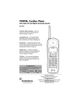
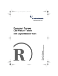
62"%JCPPGN"/QDKNG"%$"
YKVJ"&KIKVCN"%QORCUU"CPF"'."$CEMNKV".%&"&KURNC[
21-1706
#"+/2146#06"#
If an icon appears at the end of a
paragraph, go to the side head box
on that page with the
corresponding icon for pertinent
information.
Rý— Signifies a Warning
. — Signifies a Caution
# — Signifies Important text
%106'065
Attaching the Microphone Holder ........ 1
Mounting the Transceiver ................... 2
Connecting an Antenna ...................... 3
Connecting the Microphone ................ 4
Connecting an External Speaker ........ 4
Connecting a CB Speaker .......... 4
Connecting a PA Speaker .......... 4
Connecting the Compass .................... 4
Connecting an Optional
Microphone/Earphone ......................... 5
Traffic Safety .............................. 5
Using Vehicle Battery Power ............... 5
Using the Transceiver
as a Base Station ................................ 6
Using Your CB .................................... 6
Receiving Transmissions
and Adjusting Squelch .................... 6
Transmitting ..................................... 7
Selecting the Emergency Channel .. 7
Using the PA Amplifier ..................... 7
Using Monitor .................................. 8
Using the Compass ......................... 8
Using Memory ................................. 9
Using Last Channel Recall (RCL) ... 9
Adjusting the Backlight .................... 9
Transmission Courtesy .................... 9
Using Common 10-Codes ............. 10
Maximum Range ........................... 11
Troubleshooting ................................ 11
FCC Information ................................ 12
Reducing Noise ............................. 13
Care .................................................. 14
Service and Repair ........................ 14
Replacing the Fuse ....................... 14
Specifications .................................... 15
Parts and Accessories ...................... 16
."%#76+10".
Be careful not to drill into anything
behind the mounting surface.
OWNER’S MANUAL — Please read before using this equipment.
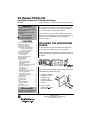
Thank you for purchasing a RadioShack 40 Channel Mobile
CB. Your CB is a great way to communicate with other CB
radio operators. You can mount it in a vehicle for mobile
use, or in your home for use as a base station.
To use this CB, you must connect a mobile or base station
antenna. Your local RadioShack store has a wide variety of
antennas. For more information, see “Connecting an
Antenna” on Page 3.
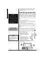
#66#%*+0)"6*'"/+%412*10'"
*1.&'4
You can attach the microphone holder to the right side of
the transceiver or to another location in your vehicle.
To attach the holder to the transceiver, secure the holder to
the right side using the supplied 3 mm machine screws and
lock washer.
To attach the holder to another location in the vehicle, such
as the dashboard, follow these steps.
1. Using the holder as a
template, mark the
positions for the
mounting screw
holes at the desired
location.
2. At each marked
position, drill a small
starter hole. .#
© 2002 RadioShack Corporation.
All Rights Reserved.
RadioShack and RadioShack.com are trademarks
used by RadioShack Corporation.
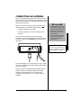
Mounting the Transceiver
3. Attach the holder at the mounting location using the
supplied machine screws, spring washers, plain
washers, and nuts.
R
"9#40+0)ý
•
•
R
/1706+0)"6*'"64#05%'+8'4
"
If you use the CB in a vehicle,
mount it securely to avoid
damage to the CB or vehicle or
injury to anyone in the vehicle
during sudden starts or stops.
Do not mount the CB where it
could damage or interfere with
the operation of any passive
restraint safety device (an
airbag or seat belt).
The most common mounting location for this CB is under a
vehicle’s dashboard. However, if you plan to use the CB as
a base station, you can place it on a desk, shelf, or table
(see “Using the Transceiver as a Base Station” on Page 6).
If you are mounting the CB in a vehicle, choose a location
where:
Rý
• You can easily reach the CB.
• Wires and cables are clear of the vehicle’s pedals or
other moving parts.
• The CB is not directly in front of heating vents.
• All wires and cables can reach their connection points.
Follow these steps to mount the CB using the supplied
hardware.
."%#76+10".
Be careful not to drill into anything
behind the mounting surface.
±"016'"±"
If you cannot reach behind the
mounting surface to attach the nuts
on the bolts or machine screws,
use the supplied plain washers and
self-tapping screws.
2
1. Using the mounting bracket as a template, mark the
positions for the screw holes on the mounting surface.
2. In each marked location, drill a small starter hole. .#
3. Mount the bracket to the
mounting surface with the
supplied 5 mm bolts, spring
washers, plain washers, and
nuts.
4. Peel the backings off the
adhesive on the back of the
supplied rubber washers and
attach the washers to the
mounting holes on the CB. Then
attach the CB to the mounting bracket using the
mounting knobs.
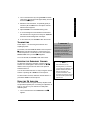
%100'%6+0)"#0"#06'00#
There are many different types of CB antennas for mobile
CBs. Each type has its own benefits, so choose the one that
best meets your needs. Your local RadioShack store sells a
wide variety of antennas.
."%#76+10".
•
Avoid routing the cable next to
sharp edges or moving parts,
which might damage the cable.
•
Do not run the cable next to
power cables or other radio
antenna cables.
•
Do not run the cable through
the engine compartment or
other areas that produce
extreme heat.
• as high as possible on the vehicle
• as far as possible from sources of electrical noise
• vertically
Once you choose an antenna, follow its mounting
instructions. Then route the cable to the transceiver and
connect the cable to the ANTENNA jack on the back of the
transceiver.
Connecting an Antenna
When you choose an antenna, keep in mind that, for the
best performance, you should mount the antenna: .#
±"016'"±"
If you are using this CB as a base
station, see “Using the Transceiver
as a Base Station” on Page 6.
Antenna
To take advantage of your radio’s maximum range, adjust
the antenna’s Standing Wave Ratio (SWR) using an SWR
meter (not supplied).
Follow the instructions supplied with the SWR meter and
antenna to adjust your antenna’s SWR to the lowest
possible value. SWR values of 2.0:1 are generally
acceptable, with readings of 1.5:1 or lower being more
desirable.
3
%100'%6+0)"6*'"
/+%412*10'
1. Align the tab on the side of the supplied microphone’s
plug with the notch in the microphone jack (on the side
of the transceiver). Then insert the plug into the jack.
2. Slide the microphone onto the microphone holder.
."%#76+10".
Never pull on the microphone
cable.
3. To disconnect the microphone from the transceiver,
press the tab on the side of the plug. Then pull out the
plug. .#
%100'%6+0)"#0"':6'40#."
52'#-'4
You can connect your transceiver to an external CB
speaker, so you can hear an incoming call when you are
outside your vehicle, or use the CB as a PA system.
%100'%6+0)"#"%$"52'#-'4
Connecting the Microphone
The external speaker you use with the transceiver should
have an impedance of 8 ohms and be able to handle 10
watts of power. The speaker cable must have a 1/8-inch
plug.
±"016'"±"
•
When you connect an external
speaker, the CB’s internal
speaker disconnects.
•
To avoid acoustic feedback, the
speaker should be at least 6
feet from the CB. If you
experience feedback, avoid
keying the microphone until you
have moved the speaker away
from the CB.
To connect the external speaker to the transceiver, insert
the speaker cable’s plug into EXT SPKR on the back of the
CB.
%100'%6+0)"#"2#"52'#-'4
The PA speaker should have an impedance of 8 ohms and
be able to handle 10 watts of power. The speaker cable
must have a 1/8-inch plug.
If your PA speaker meets the other specifications but does
not already have a 1/8-inch plug, you can connect it using a
phono plug-to-wire cable, available at your local
RadioShack store.
To connect the PA speaker to the transceiver, insert the
speaker cable’s plug into PA SPKR on the back of the CB.
%100'%6+0)"6*'"%1/2#55
Insert the compass cable’s plug into SENSOR on the back of
the CB. Do not place the compass cable near the DC cord
or the antenna cable.
4
%100'%6+0)"#0"126+10#."
/+%412*10'1'#42*10'
You can connect an optional microphone or earphone with a
3
/32-inch (2.5mm) mini plug and a 1/8-inch (3.5mm) plug to
the MIC/EAR jacks on the front of the CB. To avoid
feedback, do not connect the microphone/earphone’s 3/32inch (2.5 mm) plug to only the MIC jack in CB mode.
To connect a headset with Voice Activated operation, we
recommend you check the response sensitivity of the VOX
circuit before installation. Different Voice Activation devices
provide different performance results.
64#((+%"5#('6;
Do not use an earphone with your transceiver when
operating a motor vehicle in or near traffic. Doing so can
create a traffic hazard and could be illegal in some areas.
If you use an earphone with your transceiver be very
careful. Do not listen to a continuous broadcast. Even
though some earphones/headphones let you hear some
outside sounds when listening at normal volume levels, they
still can present a traffic hazard.
75+0)"8'*+%.'"$#66'4;"
219'4
."%#76+10".
•
Do not connect the black wire to
a non-metallic (plastic) part, or
to any part insulated from the
vehicle’s chassis by a nonmetallic part.
•
Most 13.8-volt DC power
supplies plug into a standard
AC outlet to produce DC power.
Before connecting your CB to a
13.8-volt DC power supply,
read and follow the instructions
included with the power supply.
•
To prevent damage to the CB,
be sure you connect an antenna
and the microphone before you
use your CB.
Red
Black
2. Connect the black wire to your vehicle battery’s
negative (–) terminal or to a metal part of the vehicle’s
frame (chassis ground). .#
5
Using Vehicle Battery Power
1. Connect the red wire (with the inline fuse holder) on the
back of the transceiver to a point in your vehicle’s fuse
block that has power only when the ignition is in the
ACC (accessory) or ON position.
R
"9#40+0)ý
Using Your CB
R
"
Use extreme caution when you
install or remove a base station
CB antenna. If the antenna starts
to fall, let it go! It could contact
overhead power lines. If the
antenna touches a power line,
contact with the antenna, mast,
cable, or guy wires can cause
electrocution and death. Call the
power company to remove the
antenna. Do not attempt to do so
yourself!
75+0)"6*'"64#05%'+8'4"#5"#"
$#5'"56#6+10
Although this transceiver is designed mainly for mobile use,
you can also use it as a base station with an AC power
source.
For base station installation, you need these items:
• 13.8-volt DC power supply that can supply at least 2
amps .#
• base station antenna.
• coaxial antenna cable and connectors, available at your
RadioShack store.
For the best performance, place the antenna as far as the
cable length..#
."%#76+10".
To comply with the FCC RF
Exposure compliance
requirements, a separation
distance of at least 20.0 cm must
be maintained between this
device’s antenna and all
persons.This device must transmit
with a source-based timeaveraging duty factor not
exceeding 50%.
±"016'"±"
•
Installation and Operation
instructions are for satisfying
FCC RF Exposure compliance.
•
To receive very weak signals,
turn SQUELCH
counterclockwise. You hear
noise between transmissions,
but you also hear weak
transmissions (those not strong
enough to break through a
higher squelch setting).
•
6
If you experience interference
from nearby frequencies, turn
RF GAIN counterclockwise to
reduce the receiver’s sensitivity.
Follow these steps to install the CB as a base station.
1. Mount the base station antenna as described in its
.#
owner’s manual.
Rý
2. Connect the antenna to ANTENNA on the back of the
CB.
3. Connect the transceiver’s black power wire to the
negative (–) terminal on the DC power supply.
4. Connect the transceiver’s red wire (with the in-line fuse)
to the positive (+) terminal on the DC power supply.
5. Connect the DC power supply to a standard AC outlet.
75+0)";174"%$
Before you use your CB, you should know how to use it
effectively and courteously. “Transmission Courtesy” on
Page 9 contains information that will help you get more
enjoyment from your CB.
4'%'+8+0)"64#05/+55+105"#0&"#&,756+0)"
537'.%*
1. Set PA/MON/CB to CB.
2. Turn SQUELCH fully counterclockwise.
3. Turn RF GAIN fully clockwise.
Using Your CB
4. Turn on the transceiver by turning VOLUME clockwise
until it clicks. All LCD segments appear briefly. Then the
channel and HN appear.
5. Rotate the channel selector, or repeatedly press (or
hold down) UP or DOWN on the microphone until the
desired channel appears.
6. Adjust VOLUME to a comfortable listening level.
7. To cut out background noise between transmissions,
wait until there is no signal, then slowly turn SQUELCH
clockwise until the background noise stops.
8. To turn off the CB, turn VOLUME to OFF until it clicks.
64#05/+66+0)
Follow Steps 1–7 in “Receiving Transmissions and
Adjusting Squelch.”
To transmit, hold down PUSH TO TALK on the microphone.
JN appears. Hold the microphone 2–3 inches from your
mouth and speak in a normal tone of voice, then release
PUSH TO TALK when you finish. JN disappears.
To turn off the CB, turn VOLUME to OFF until it clicks.
#"+/2146#06"#
Channel 9 and Channel 19 are
reserved for motorist assistance
and for reporting emergency
information about accidents,
hazardous road conditions, and so
on. Always give emergency
messages priority on Channel 9 or
Channel 19.
5'.'%6+0)"6*'"'/'4)'0%;"%*#00'.
To select the emergency channel 9, press the channel
selector once. Press again to select channel 19. / or '/
flashes. Press one more time to return to the previous
selected channel. #"
You can also select Channel 9 or 19 by turning the channel
selector or pressing UP or DOWN on the microphone.
To select another channel, rotate the channel selector or
press UP or DOWN on the microphone.
±"016'"±"
•
We recommend you try
receiving before you transmit.
•
To avoid acoustic feedback, the
speaker should be at least 6
feet from the CB. If you
experience feedback, avoid
keying the microphone until you
have moved the speaker away
from the CB.
75+0)"6*'"2#"#/2.+(+'4
Your CB has a built-in PA (public address) amplifier. With
an optional PA speaker (see “Connecting a PA Speaker” on
Page 4), you can turn your radio into a mobile public
address system.
1. Turn on the transceiver. Set PA/MON/CB to PA. F7
appears.
7
2. To transmit, hold down PUSH TO TALK on the
microphone. Hold the microphone 2–3 inches from your
mouth and speak in a normal tone of voice.
Using Your CB
3. Turn VOLUME for the desired volume level. If you hear
high-pitched squeal, turn VOLUME counterclockwise
until the squeal stops.
4. To turn off the PA amplifier, turn the transceiver off. Or,
set PA/MON/CB to CB for CB communication.
75+0)"/10+614
You can use your CB as a receiver to listen to transmissions
on an optional PA speaker. With a PA speaker connected,
set PA/MON/CB to MON. Your CB cannot transmit and you
hear sound only from the external PA speaker.
75+0)"6*'"%1/2#55
±"016'"±"
•
Before calibration, end CB
transmission and make sure the
CB is not tuned to the
Emergency channel 9 or 19 or
in PA mode.
•
Do not calibrate the compass
near metal or a strong magnetic
field.
•
The compass is not available in
TX mode.
You can easily view your current heading at a glance. There
are eight cardinal points on the display — north, northeast,
east, southeast, south, southwest, west, northwest.
Calibration helps the compass better separate the earth’s
magnetic field from the magnetic field generated by external
influences (such as your vehicle), providing more accurate
heading information.
Calibrate the compass anytime you move it, or whenever
distortion continuously appears. Before calibration, peel off
the backing on one side of the supplied tape and attach the
tape to the back of the compass, then mount the compass
by peeling off the backing on the other side of the tape, then
press the compass onto the level mounting surface, with the
compass’ arrow facing up and pointing to the front. Do not
mount the compass upside down.
1. Hold down CAL for a second. All eight cardinal points
flash.
2. Drive your vehicle in two complete circles. Be sure your
vehicle is on level ground, in an open area, such as a
parking lot.
3. Press CAL to confirm calibration
You must complete the circles on level ground and press
CAL within 10 minutes. Or, start from Step 1 again.
If an error is found during calibration, ;h appears for a few
seconds. Move the compass to another place and start from
Step 1 again.
8
Using Your CB
After calibration, the current compass heading displays. For
example, if the compass heading is south, the south
cardinal point appears. Or, if the compass heading is
northeast-north, the northeast cardinal point appears and
the north cardinal point flashes.
75+0)"/'/14;
You can store three channels in the memory. The preset
channel stored in MEM1, MEM2, and MEM3 is Channel 1.
Press the memory location number to switch to the stored
channel. The channel number, C;C and the memory
location number appear.
±"016'"±"
•
When you rotate the channel
selector or press UP or DOWN
on the microphone to turn to the
channel stored in the memory,
C;C and the memory location
number appear.
•
The channel will only be saved
to RCL memory when the
current channel is manually
turned using the rotary switch or
UP or DOWN on the
microphone and stays on the
channel for more than 3
seconds.
•
You cannot recall an emergency
channel or a memory channel
by pressing RCL.
1. Select the desired channel.
2. Briefly hold down the desired memory location button.
C;C and the memory location number flash twice.
75+0)".#56"%*#00'."4'%#.."*4%.+
In CB or monitor mode, press RCL to return to the last
channel used for more than 3 seconds. Press RCL again to
return to the previous channel.
#&,756+0)"6*'"$#%-.+)*6
You can adjust the backlight by rotating DIMMER. To turn off
the backlight, rotate DIMMER fully counterclockwise.
64#05/+55+10"%1746'5;
Follow these guidelines for radio courtesy when using your
CB.
• Wait for a pause in someone else’s transmission before
you ask for a break.
• If you do not receive an answer to your call after a
second attempt, sign off and wait several minutes
before trying again.
• Do not hold down PUSH TO TALK when you are not
talking. (This is called dead keying.)
• Assist callers with directions, information about road
conditions, and any other reasonable requests.
9
75+0)"%1//10"32/%1&'5
Using Your CB
CB users have adopted the 10-codes for standard
questions and answers. This table lists common codes
adopted by the Associated Public Safety Communications
Officers (APCO).
%QFG
±"016'"±"
Although the table lists the 10codes’ meanings in the form of a
statement, they can also be
phrased as questions (10-6: Are
you busy?, 10-20: What is your
location?).
10
/GCPKPI
10-1
Your signal is bad.
10-2
Your signal is good.
10-3
Stop transmitting.
10-4
Message received and understood.
10-5
Relay information to ________.
10-6
I am busy or are you busy?
10-7
Out of service.
10-8
In service.
10-9
Repeat last message.
10-10
Negative (NO).
10-11
________ in service.
10-12
Stand by.
10-13
Report road/weather conditions.
10-14
Information.
10-15
Message delivered.
10-16
Reply to message.
10-17
En route.
10-18
Urgent.
10-19
Contact _________.
10-20
What is your location?
10-21
Call ________ by telephone.
10-22
Cancel last message.
10-23
Arrived at the scene.
10-24
Assignment complete.
10-25
Meet __________
10-26
Estimated time of arrival is _____________.
10-30
Use caution.
10-31
Pick up.
10-33
Emergency traffic. Clear the channel.
10-34
What time is it?
10-41
Switch to Channel __________.
10-62
Cannot understand.
/#:+/7/"4#0)'
The maximum range and quality of CB radio transmissions
vary depending on the following conditions:
• The type and quality of antenna used
• The height of the antenna’s mounting location — the
higher the antenna, the better the signal’s range
±"016'"±"
Your CB radio’s transmission
range is generally line-of-sight.
• The surrounding terrain — mountains and tall buildings
limit the range
• Weather conditions
• The number of nearby radios operating on the same
channel
Troubleshooting
• Standing wave ratio (SWR) between the antenna and
the CB.
6417$.'5*116+0)
If your CB is not working as it should, follow these
suggestions to see if you can eliminate the problem. If you
cannot, take the CB to your local RadioShack store for
assistance.
2TQDNGO
5WIIGUVKQP
Turn transceiver power on.
Microphone connected? Secure connections.
Antenna connected? Secure connections.
CB has trouble
receiving.
Too much squelch? Adjust as needed.
Radio not on operating channel? Switch to an
active channel.
Be sure PA/MON/CB is set to CB.
Adjust VOLUME.
Adjust RF GAIN.
Turn transceiver power on.
Antenna connected? Secure connections.
All connections free of corrosion? Clean and
tighten.
CB has trouble
transmitting.
Microphone connector loose? Firmly press
microphone connector into jack.
Be sure PA/MON/CB is set to CB.
Radio not on operating channel? Switch to an
active channel.
PUSH TO TALK fully pressed? Press
completely.
11
2TQDNGO
5WIIGUVKQP
Power connected? Secure connections.
CB does not
work at all.
Cannot select a
channel.
Microphone connected? Secure connections.
Fuse needs replacing? Replace with identical
fuse. See “Replacing the Fuse” on Page 14.
Be sure PA/MON/CB is set to CB.
PUSH TO TALK pressed? Release PUSH TO
TALK.
Connect a PA speaker. Secure connections.
PA does not
work.
Be sure PA/MON/CB is set to PA.
Adjust VOLUME.
FCC Information
R
"9#40+0)ý
R
Sound is
distorted.
Adjust RF GAIN.
Compass
bearing shows
the same
reading even
when steering to
other direction.
Be sure the compass cable is properly
connected.
Adjust VOLUME.
There might be magnetic material/interference
near the compass sensor. Move the compass
sensor away from the magnetic material/
interference and recalibrate the compass.
(%%"+0(14/#6+10
"
Do not open the CB radio to make
any internal adjustments. A CB
radio is set up to transmit a
regulated signal on an assigned
frequency. It is against the law to
alter or adjust the settings inside
the unit to exceed these
limitations.
The Federal Communications Commission (FCC) does not
require you to have a license to operate this CB radio.
However, you must know Part 95 of FCC Rules. It explains
the proper operation of a Class D citizen’s band transceiver.
We enclosed a copy of Part 95 with your CB radio.
Rý
To be safe and sure:
• Never open your CB radio’s case.
• Never change or replace anything in your CB radio.
Your CB radio might cause TV or radio interference even
when it is operating properly. To determine whether your CB
is causing the interference, turn off your CB. If the
interference goes away, your CB is causing it. Try to
eliminate the interference by:
• moving your CB away from the receiver
• contacting your local RadioShack store for help
This device complies with Part 15 of the following two
conditions: (1) this device may not cause harmful
interference, and (2) this device must accept any
interference received, including interference that may cause
undesired operation.
12
4'&7%+0)"01+5'
Because your CB is exceptionally quiet, any noise you hear
is probably from an external source in your vehicle such as
the alternator, another radio or spark plugs.
The transceiver uses an ANL (Automatic Noise Limiter)
circuit to reduce noise. However, if possible, try to eliminate
noise by finding its source.
You can determine the noise’s source by turning off the
engine and operating the CB with your vehicle’s ignition set
to ACC. If the noise is reduced, the problem is in your
vehicle’s ignition or electrical system.
Here are a few hints to help you reduce or eliminate such
noise:
• Make all CB power and antenna wires as short as
possible.
• Route the power wires away from the antenna wires.
• Be sure that the chassis ground connection is secure.
• Replace old ignition wires with new, high-voltage, noise
suppression wires.
• Install noise suppressors on your spark plugs, or install
new spark plugs that have built-in noise suppressors.
• If problems persist, check your alternator/generator and
regulator gauges. You can reduce the noise from these
sources by using bypass capacitors at the various
output voltage points.
Reducing Noise
Your local RadioShack store has a wide selection of noise
suppression accessories.
13
%#4'
Care
Keep the CB dry; if it gets wet, wipe it dry immediately. Use
and store the CB only in normal temperature environments.
Handle the CB carefully; do not drop it. Keep the CB away
from dust and dirt, and wipe it with a damp cloth
occasionally to keep it looking new.
5'48+%'"#0&"4'2#+4
If your CB is not performing as it should, take it to your local
RadioShack store for assistance. Modifying or tampering
with the CB’s internal components can cause a malfunction
and might invalidate its warranty.
."%#76+10".
Do not use a fuse with ratings
other than those specified. Doing
so might damage your CB.
4'2.#%+0)"6*'"(75'
The CB’s 2-amp in-line fuse helps protect your CB from
power surges and short circuits. When replacement is
required, use a 2-amp, slow-blow glass fuse. .#
1. Make sure the power source and CB are both off.
2. Hold the fuse holder by both ends, push the ends
together, twist one end counterclockwise, then pull
them apart.
3. Remove the old fuse. If it is blown, insert a new one of
the same type and rating. If it is not blown, reinsert it.
4. Push the fuse holder ends together and twist one end
clockwise.
14
RECEIVER
Frequency Coverage ..... All 40 CB Channels, 26.965-27.405 MHz
Sensitivity for 10dB S/N ........................................................ 0.5 uV
Squelch Sensitivity ............................................................. 1000 uV
Overall Audio Fidelity for 450-2500 Hz ................................... –6dB
Maximum Audio Output Power ........................................... 6 Watts
RF Gain Control Range (at 10 dB Input) ................................ 45dB
TRANSMITTER
Frequency Coverage ..... All 40 CB Channels, 26.965-27.405 MHz
Frequency Tolerance ............................................... 1300 ± 100 Hz
Carrier Power at No Modulation ...................................... 3.7 Watts
Spurious Emission ............................................................... –67 dB
Current Drain at No Modulation ........................................ 1000 mA
Modulation Frequency Response for 450-2500 Hz ............... –6 dB
Microphone Sensitivity for 50% Modulation ............................ 2 mV
PUBLIC ADDRESS AMPLIFIER
Maximum Output Power ..................................................... 6 Watts
Microphone Sensitivity for 4 Watts Output Power ................... 3 mV
Frequency Response for 450-2500 Hz .................................. –6 dB
Current Drain at Maximum Output Power ......................... 1000 mA
GENERAL
Power Requirements .................... 13.8 Volts DC Negative Ground
Dimension .................... 67/16 × 21/16 × 77/8 in (163 × 52 × 200 mm)
Weight ................................................................ 1 lb 12 oz (0.8 kg)
Specifications are typical, individual units might vary. Specifications
are subject to change and improvement without notice.
Limited Ninety-Day Warranty
This product is warranted by RadioShack
against manufacturing defects in material and
workmanship under normal use for ninety (90)
days from the date of purchase from
RadioShack company-owned stores and authorized RadioShack franchisees and dealers. EXCEPT AS PROVIDED HEREIN,
RadioShack MAKES NO EXPRESS WARRANTIES AND ANY IMPLIED WARRANTIES,
INCLUDING THOSE OF MERCHANTABILITY
AND FITNESS FOR A PARTICULAR PURPOSE, ARE LIMITED IN DURATION TO THE
DURATION OF THE WRITTEN LIMITED
WARRANTIES CONTAINED HEREIN. EXCEPT AS PROVIDED HEREIN, RadioShack
SHALL HAVE NO LIABILITY OR RESPONSIBILITY TO CUSTOMER OR ANY OTHER
PERSON OR ENTITY WITH RESPECT TO
ANY LIABILITY, LOSS OR DAMAGE
CAUSED DIRECTLY OR INDIRECTLY BY
USE OR PERFORMANCE OF THE PRODUCT OR ARISING OUT OF ANY BREACH
OF THIS WARRANTY, INCLUDING, BUT
NOT LIMITED TO, ANY DAMAGES RESULTING FROM INCONVENIENCE, LOSS OF
TIME, DATA, PROPERTY, REVENUE, OR
PROFIT OR ANY INDIRECT, SPECIAL, INCIDENTAL, OR CONSEQUENTIAL DAMAGES,
EVEN IF RadioShack HAS BEEN ADVISED
OF THE POSSIBILITY OF SUCH DAMAGES.
Some states do not allow limitations on how
long an implied warranty lasts or the exclusion
or limitation of incidental or consequential
damages, so the above limitations or exclusions may not apply to you.
In the event of a product defect during the warranty period, take the product and the
RadioShack sales receipt as proof of purchase
date to any RadioShack store. RadioShack
will, at its option, unless otherwise provided by
law: (a) correct the defect by product repair
without charge for parts and labor; (b) replace
the product with one of the same or similar design; or (c) refund the purchase price. All replaced parts and products, and products on
which a refund is made, become the property
of RadioShack. New or reconditioned parts
and products may be used in the performance
of warranty service. Repaired or replaced
parts and products are warranted for the remainder of the original warranty period. You
will be charged for repair or replacement of the
product made after the expiration of the warranty period.
This warranty does not cover: (a) damage or
failure caused by or attributable to acts of God,
abuse, accident, misuse, improper or abnormal usage, failure to follow instructions, improper installation or maintenance, alteration,
lightning or other incidence of excess voltage
or current; (b) any repairs other than those
provided by a RadioShack Authorized Service
Facility; (c) consumables such as fuses or batteries; (d) cosmetic damage; (e) transportation, shipping or insurance costs; or (f) costs of
product removal, installation, set-up service
adjustment or reinstallation.
This warranty gives you specific legal rights,
and you may also have other rights which vary
from state to state.
RadioShack Customer Relations, 200 Taylor
Street, 6th Floor, Fort Worth, TX 76102
12/99
15
Specifications
52'%+(+%#6+105
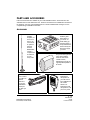
2#465"#0&"#%%'5514+'5
Parts and accessories are available at your local RadioShack store. Accessories are also
available online at www.radioshack.com. Parts and accessories are available but not limited to
the following. Visit your local RadioShack store or obtain a RadioShack catalog for a more
complete listing of available accessories.
#%%'5514+'5
For the best
possible
reception, at
home or on
the go, you
can connect
an optional
external
antenna.
RadioShack
carries a
complete line
of antennas
for your
every need.
If you would
like to connect
your CB to an
optional
antenna of
your choice,
RadioShack
carries just
the cable you
need.
RadioShack Corporation
Fort Worth, Texas 76102
Your CB also
makes a great
base station in
your home. To
make setting up
the base station a
snap, RadioShack
stocks exactly the
DC power supply
you need.
So you can hear your CB
even while rumbling
down the road in the
noisiest vehicle,
RadioShack has just the
right amplified speaker to
fit the bill.
Need a
replacement
microphone for
your CB? Never
fear, RadioShack
has a wide
selection of
replacement CB
microphones, to fit
your every need.
21-1706
AO0083AAA1
02A02
Printed in China