1
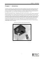
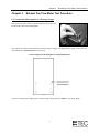
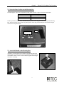
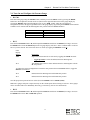
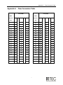
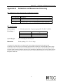
Exhaust Fan Flow Meter™ Operation Manual Exhaust Fan Flow Meter™ Operation Manual The Energy Conservatory 2801 21st Ave. S., Suite 160 Minneapolis, MN 55407 612-827-1117 Fax 612-827-1051 www.energyconservatory.com email: [email protected] Exhaust Fan Flow Meter is a trademark of The Energy Conservatory, Inc. Manual Edition: August 2012 Copyright 2012. The Energy Conservatory, Inc. All rights reserved. ENERGY CONSERVATORY WARRANTY EXPRESS LIMITED WARRANTY: Seller warrants that this product, under normal use and service as described in the operator’s manual, shall be free from defects in workmanship and material for a period of 24 months, or such shorter length of time as may be specified in the operator’s manual, from the date of shipment to the Customer. LIMITATION OF WARRANTY AND LIABILITY: This limited warranty set forth above is subject to the following exclusions: a) b) c) d) With respect to any repair services rendered, Seller warrants that the parts repaired or replaced will be free from defects in workmanship and material, under normal use, for a period of 90 days from the date of shipment to the Purchaser. Seller does not provide any warranty on finished goods manufactured by others. Only the original manufacturer’s warranty applies. Unless specifically authorized in a separate writing, Seller makes no warranty with respect to, and shall have no liability in connection with, any goods which are incorporated into other products or equipment by the Purchaser. All products returned under warranty shall be at the Purchaser’s risk of loss. The Purchaser is responsible for all shipping charges to return the product to The Energy Conservatory. The Energy Conservatory will be responsible for return standard ground shipping charges. The Customer may request and pay for the added cost of expedited return shipping. The foregoing warranty is in lieu of all other warranties and is subject to the conditions and limitations stated herein. No other express or implied warranty IS PROVIDED, AND THE SELLER DISCLAIMS ANY IMPLIED WARRANTY OF FITNESS for particular purpose or merchantability. The exclusive remedy of the purchaser FOR ANY BREACH OF WARRANTY shall be the return of the product to the factory or designated location for repair or replacement, or, at the option of The Energy Conservatory, refund of the purchase price. The Energy Conservatory’s maximum liability for any and all losses, injuries or damages (regardless of whether such claims are based on contract, negligence, strict liability or other tort) shall be the purchase price paid for the products. In no event shall the Seller be liable for any special, incidental or consequential damages. The Energy Conservatory shall not be responsible for installation, dismantling, reassembly or reinstallation costs or charges. No action, regardless of form, may be brought against the Seller more than one year after the cause of action has accrued. The Customer is deemed to have accepted the terms of this Limitation of Warranty and Liability, which contains the complete and exclusive limited warranty of the Seller. This Limitation of Warranty and Liability may not be amended or modified, nor may any of its terms be waived except by a writing signed by an authorized representative of the Seller. TO ARRANGE A REPAIR: Please call The Energy Conservatory at 612-827-1117 before sending any product back for repair or to inquire about warranty coverage. All products returned for repair should include a return shipping address, name and phone number of a contact person concerning this repair, and the purchase date of the equipment. Table of Contents Operation Manual for Exhaust Fan Flow Meter Chapter 1 Introduction 1 Chapter 2 Exhaust Fan Flow Meter Test Procedure 2 2.1 2.2 2.3 2.4 2.5 Connect the Metering Box to a Pressure Gauge 2 Select the Door Position on the Metering Box 3 Attach the Handle to the Metering Box 3 Turn On and Configure the Pressure Gauge 4 Place Metering Box Over Exhaust Fan Grille and Determine Flow Reading 5 Appendix A Flow Conversion Table 7 Appendix B Calibration and Measurement Accuracy 8 B.1 Calibration Formulas 8 B.2 Specifications 8 Chapter 1 Chapter 1 Introduction Introduction The Energy Conservatory's (TEC) Exhaust Fan Flow Meter is designed to make quick and accurate measurements of air flow through residential exhaust fans. The effective air flow measurement range for the Exhaust Fan Flow Meter is 10 to 124 cubic feet per minute (CFM). The device should be used along with a pressure gauge providing 0.1 Pascals (0.0004 in. w.c.) of resolution in the range of 1 to 8 Pascals. When used with TEC's DG-700, DG-3 or DG-2 digital pressure gauges, the accuracy of the exhaust fan flow measurement is +/- 10%. During the measurement procedure, the Exhaust Fan Flow Meter is placed directly over the exhaust fan grille and is pushed up against the wall or ceiling so that the flexible gasket on the end of the Metering Box creates an air tight seal around the grille. The pressure reading taken from the Exhaust Fan Flow Meter is easily converted to air flow in CFM using a flow table attached to the side of the Metering Box. The DG-700 or DG-3 digital pressure gauge can also be set up to display air flow readings directly in CFM. The Exhaust Fan Flow Meter has 3 calibrated openings to provide an accurate measurement over the full range of the device. A short handle is provided which can be attached to the Metering Box using Velcro strips. The handle is designed to allow a standard painter’s pole or broom handle (not included) to be screwed into the open end of the handle to provide access to exhaust fan grilles mounted high on walls, or on ceilings. Exhaust Fan Flow Meter with DG-700 Pressure Gauge 1 Chapter 2 Chapter 2 Exhaust Fan Flow Meter Test Procedure Exhaust Fan Flow Meter Test Procedure 2.1 Connect the Metering Box to a Pressure Gauge First connect one end of a piece of flexible tubing to the pressure tap located in the corner of the Metering Box. Now connect the other end of the tubing to a pressure gauge. If using a TEC digital pressure gauge, connect the end of the tubing to the Channel B "Input" pressure tap. Connect Tubing from Metering Box to Channel B Input Tap Connect tubing from Metering Box to the Channel B Input tap If you are not using a TEC digital gauge, connect the end of the tubing to the Input or + tap on the gauge. 2 Chapter 2 Exhaust Fan Flow Meter Test Procedure 2.2 Select the Door Position on the Metering Box The Metering Box comes with an adjustable opening which provides 3 ranges of fan flow measurement. Door Position E1 E2 E3 Flow Range (CFM) 44 -124 21 - 59 10 - 28 The door position (E1, E2 or E3) is determined by the position of the snap pin located on the top of the Metering Box. The door position can be adjusted by pushing down on the snap pin and sliding the door until the snap pin reseats into a new position hole. Door Snap Pin Position Holes 2.3 Attach the Handle to the Metering Box A handle is provided which can be attached to the Metering Box using Velcro strips. You can also screw in your own painter’s pole into the end of the handle to make it easier to reach exhaust fan grilles mounted high on walls, or on ceilings. 3 Chapter 2 Exhaust Fan Flow Meter Test Procedure 2.4 Turn On and Configure the Pressure Gauge DG-700 First turn on the gauge using the ON/OFF button, and then put it in the PR/ FL mode by pressing the MODE button once. Now adjust the selected test device (shown in the upper left hand corner of the gauge display) by pressing the DEVICE button until the DEVICE icon is set to EXH. Finally, adjust the selected device configuration (shown in the upper right hand corner of the gauge display) by pressing the CONFIG button until the CONFIG icon is matched with the Metering Box door position chosen in Section 2.2 above. Door Position E1 E2 E3 CONFIG Icon on DG-700 A1 B2 C3 DG-3 First turn the CHANNEL knob to B, and then push the RANGE switch down to 200.0 Pa (low range). Now turn the MODE knob to the FAN SELECT position. The gauge display will show "-SEL" to indicate that a test device has not yet been selected. The selected test device is chosen by toggling the SELECT switch up. If the Display Shows -SEL Description Begin flow measurement device selection by toggling the SELECT switch: - -E-1 toggle up 5 times to select the Exhaust Fan Flow Metering Box. This indicates that you have chosen Exhaust Fan Flow Metering Box with the E1 door position. To change the selected configuration to match the door position chosen in Section 2.2 above, toggle the SELECT switch down. -E-2 Exhaust Fan Flow Metering Box with the E2 door position. -E-3 Exhaust Fan Flow Metering Box with the E3 door position. Once the proper door position has been selected, turn the MODE switch to FLOW (CFM). Note: DG-3 gauges sold prior to April 2001 may not have the E option when selecting a test device. These gauges can be retrofitted with a new EPROM by The Energy Conservatory (call for more information). DG-2 First turn the CHANNEL knob to B, and then push the RANGE switch down to 200.0 Pa (low range). Now turn the MODE knob to the 1 SEC. AVERAGE position. 4 Chapter 2 Exhaust Fan Flow Meter Test Procedure 2.5 Place Metering Box Over Exhaust Fan Grille and Determine Flow Reading With the exhaust fan turned on, place the Metering Box completely over the fan grille so that the flexible gasket on the end of the Metering Box creates an air tight seal around the grille. If using a TEC digital gauge, hold the gauge steady for at least 10 seconds so that the gauge auto-zeros. If you are not using a TEC digital gauge, be sure to follow the manufacturer's pressure zeroing instructions before placing the Metering Box over the exhaust fan grille. Determine the air flow reading as shown below: DG-700 The air flow reading from the exhaust fan will be shown directly on Channel B display. If the flow reading is fluctuating, you may want to change the time-average setting on the gauge (TIME AVG button). The displayed flow units can also be changed by pressing the UNITS button (default units are CFM). Note: If “LO” appears on Channel B, the air flow reading is below the calibrated range of the test device in its current configuration. If possible, you should change the test device configuration to match the flow rate being measured (e.g. change the door position to a smaller opening). If you change the door position on the Metering Box, be sure to change the CONFIG setting on the gauge to match the new door position. DG-3 The air flow reading from the exhaust fan will be shown directly on the gauge display in units of CFM. If the flow reading is fluctuating, you may want to change the time-average setting on the gauge (using the TIME SELECT mode). Note: If you are trying to measure a flow below the calibrated range of the test device in its current configuration, the gauge will display 0000. If possible, you should change the test device configuration to match the flow rate being measured (e.g. change the door position to a smaller opening). If you change the door position on the Metering Box, be sure to change the test device setting on the gauge (using the FAN SELECT mode) to match the new door position. DG-2 or Other Pressure Gauge The DG-2 (or other pressure gauge) will display the pressure signal from the Metering Box in Pascals. If the pressure reading is fluctuating, you may want to change the time-average setting on the gauge. The gauge pressure reading can now be converted to air flow in CFM using the flow table on the side of the Metering Box, or the flow table in Appendix A. Be sure you are using the Flow column (E1, E2 or E3) which corresponds to the Metering Box door position used during the test. Example: With the door position set to E2, a Metering Box pressure of 3.8 Pascals was measured. Using the E2 column on the flow conversion table, the measured flow through the Exhaust Fan Flow Meter is 40 CFM. 5 Chapter 2 Exhaust Fan Flow Meter Test Procedure Acceptable Metering Box Pressures: When using the Exhaust Fan Flow Meter, the measured Metering Box pressure should never be greater than 8.0 Pascals, and never lower than 1.0 Pascals. Pressures above 8.0 Pascals will commonly result in erroneous flow measurements because the Metering Box will tend to restrict air flow through typical residential exhaust fans. Metering Box pressures below 1.0 Pascal are too small to measure accurately. Metering Box Pressure Greater than 8.0 If the measured Metering Box pressure is above 8.0 Pascals, first check the door position. If the door position is set to E2 or E3, adjust the position to create a larger opening in the Metering Box (e.g. E1 or E2). If the door position is set to E1 (the largest opening) and the Metering Box pressure is still above 8.0 Pascals, then the fan flow you are trying to measure is outside the high range of the instrument (i.e. flow is greater than 124 CFM). Metering Box Pressure Less than 1.0 Pascal If the measured Metering Box pressure is below 1.0 Pascal, first check the door position. If the door position is set to E1 or E2, adjust the position to create a smaller opening in the Metering Box (e.g. E2 or E3). If the door position is set to E3 (the smallest opening) and the Metering Box pressure is still below 1.0 Pascal, then the fan flow you are trying to measure is outside the low range of the instrument (i.e. flow is less than 10 CFM). Note: Both the DG-700 and DG-3 gauges warn you if the Metering Box pressure is less than 1.0 Pascal (see above). 6 Appendix A Appendix A Flow Conversion Table Flow (CFM) Flow (CFM) Meter Pressure Flow Conversion Table Meter E1 E2 E3 Pressure (Pa) E1 E2 E3 4.4 92 43 21 4.6 94 44 22 (Pa) 1.0 44 21 10 4.8 96 45 22 1.2 48 23 11 5.0 98 46 23 1.4 52 25 12 5.2 100 47 23 1.6 55 26 13 5.4 102 48 23 1.8 59 28 14 5.6 103 49 24 2.0 62 29 14 5.8 105 50 24 2.2 65 31 15 6.0 107 51 25 2.4 68 32 16 6.2 109 52 25 2.6 71 33 16 6.4 111 52 25 2.8 73 35 17 6.6 112 53 26 3.0 76 36 17 6.8 114 54 26 3.2 78 37 18 7.0 116 55 27 3.4 81 38 19 7.2 117 56 27 3.6 83 39 19 7.4 119 56 27 3.8 85 40 20 7.6 121 57 28 4.0 87 41 20 7.8 122 58 28 4.2 90 42 21 8.0 124 59 28 7 Appendix B Appendix B Calibration and Measurement Accuracy Calibration and Measurement Accuracy B.1 Exhaust Fan Flow Metering Box Calibration Formula Door Opening E1 E2 E3 Formula Flow (CFM) = 43.73 x (Metering Box Pressure in Pascals)0.5 Flow (CFM) = 20.72 x (Metering Box Pressure in Pascals)0.5 Flow (CFM) = 10.07 x (Metering Box Pressure in Pascals)0.5 B.2 Specifications Flow Accuracy: Flow Range: * +/- 10% when used with a 1% pressure gauge (DG-700, DG-3 or DG-2). Door Position E1 E2 E3 Flow Range (CFM) 44 -124 21 - 59 10 - 28 System Weight: 4 lbs. including the extension pole. Dimensions: Inside opening (13” x 16” x 8” deep). * The upper flow range limit of 124 CFM is based on the assumption that back pressures greater than 8.0 Pascals will start to restrict air flow through typical residential exhaust fans. The Metering Box will accurately measure flows above 124 CFM, however the measured flow may be less than the actual flow through the exhaust fan under normal operating conditions. Referring to the manufacturer's published fan curve for the exhaust fan being tested will allow you to estimate how much the back pressure added by the Metering Box has reduced the air flow through the exhaust fan. 8


![[PF03] User manual for WHITE-COLOR DOT - Auto](http://vs1.manualzilla.com/store/data/005728816_1-b07d7d3c2bb75a06da64907106241247-150x150.png)