1
Scaler Video Processor
User Manual
!
△
Before using this Scaler Video processor please read this
manual carefully and preserved for reference in the future.
Model Dcdi 550
Statements
Without the written permission, any unit or individual could
not copy, reproduction or translate the book or part of it. Also
could not transmit it in any form or any way (electronic,
mechanical, photocopying, record or other way) for any
business and profitable purpose.
The product specifications and information mentioned in this
manual is just for reference, will not give prior notice if there
is any updated. Unless there is a special agreement, it is just
used as guidelines. All the statements or information in this
manual shall not constitute any form of guarantee.
Directory
BRIEFS ·∙·∙·∙·∙·∙·∙·∙·∙·∙·∙·∙·∙·∙·∙·∙·∙·∙·∙·∙·∙·∙·∙·∙·∙·∙·∙·∙·∙·∙·∙·∙·∙·∙·∙·∙·∙·∙·∙·∙·∙·∙·∙·∙·∙·∙·∙·∙·∙·∙·∙·∙·∙·∙·∙·∙·∙·∙·∙·∙·∙·∙·∙·∙·∙·∙·∙·∙·∙·∙·∙·∙·∙·∙·∙·∙·∙·∙·∙·∙·∙·∙·∙·∙·∙·∙·∙·∙·∙·∙·∙·∙·∙·∙·∙·∙·∙·∙·∙·∙·∙·∙·∙·∙·∙·∙·∙·∙·∙·∙·∙·∙·∙·∙ 3 TRADEMARK CREDIT ·∙·∙·∙·∙·∙·∙·∙·∙·∙·∙·∙·∙·∙·∙·∙·∙·∙·∙·∙·∙·∙·∙·∙·∙·∙·∙·∙·∙·∙·∙·∙·∙·∙·∙·∙·∙·∙·∙·∙·∙·∙·∙·∙·∙·∙·∙·∙·∙·∙·∙·∙·∙·∙·∙·∙·∙·∙·∙·∙·∙·∙·∙·∙·∙·∙·∙·∙·∙·∙·∙·∙·∙·∙·∙·∙·∙·∙·∙·∙·∙·∙·∙·∙·∙·∙·∙·∙·∙·∙·∙·∙·∙·∙·∙·∙·∙·∙·∙ 3 ABOUT SOFTWARE ·∙·∙·∙·∙·∙·∙·∙·∙·∙·∙·∙·∙·∙·∙·∙·∙·∙·∙·∙·∙·∙·∙·∙·∙·∙·∙·∙·∙·∙·∙·∙·∙·∙·∙·∙·∙·∙·∙·∙·∙·∙·∙·∙·∙·∙·∙·∙·∙·∙·∙·∙·∙·∙·∙·∙·∙·∙·∙·∙·∙·∙·∙·∙·∙·∙·∙·∙·∙·∙·∙·∙·∙·∙·∙·∙·∙·∙·∙·∙·∙·∙·∙·∙·∙·∙·∙·∙·∙·∙·∙·∙·∙·∙·∙·∙·∙·∙·∙·∙·∙ 3 FEATURES ·∙·∙·∙·∙·∙·∙·∙·∙·∙·∙·∙·∙·∙·∙·∙·∙·∙·∙·∙·∙·∙·∙·∙·∙·∙·∙·∙·∙·∙·∙·∙·∙·∙·∙·∙·∙·∙·∙·∙·∙·∙·∙·∙·∙·∙·∙·∙·∙·∙·∙·∙·∙·∙·∙·∙·∙·∙·∙·∙·∙·∙·∙·∙·∙·∙·∙·∙·∙·∙·∙·∙·∙·∙·∙·∙·∙·∙·∙·∙·∙·∙·∙·∙·∙·∙·∙·∙·∙·∙·∙·∙·∙·∙·∙·∙·∙·∙·∙·∙·∙·∙·∙·∙·∙·∙·∙·∙·∙·∙·∙·∙·∙ 3 USING DIRECTIONS ·∙·∙·∙·∙·∙·∙·∙·∙·∙·∙·∙·∙·∙·∙·∙·∙·∙·∙·∙·∙·∙·∙·∙·∙·∙·∙·∙·∙·∙·∙·∙·∙·∙·∙·∙·∙·∙·∙·∙·∙·∙·∙·∙·∙·∙·∙·∙·∙·∙·∙·∙·∙·∙·∙·∙·∙·∙·∙·∙·∙·∙·∙·∙·∙·∙·∙·∙·∙·∙·∙·∙·∙·∙·∙·∙·∙·∙·∙·∙·∙·∙·∙·∙·∙·∙·∙·∙·∙·∙·∙·∙·∙·∙ 4 INCLUDED ACCESSORIES ·∙·∙·∙·∙·∙·∙·∙·∙·∙·∙·∙·∙·∙·∙·∙·∙·∙·∙·∙·∙·∙·∙·∙·∙·∙·∙·∙·∙·∙·∙·∙·∙·∙·∙·∙·∙·∙·∙·∙·∙·∙·∙·∙·∙·∙·∙·∙·∙·∙·∙·∙·∙·∙·∙·∙·∙·∙·∙·∙·∙·∙·∙·∙·∙·∙·∙·∙·∙·∙·∙·∙·∙·∙·∙·∙·∙·∙·∙·∙·∙·∙·∙·∙·∙·∙·∙·∙·∙·∙·∙·∙·∙·∙ 4 EXTENDED PORT ·∙·∙·∙·∙·∙·∙·∙·∙·∙·∙·∙·∙·∙·∙·∙·∙·∙·∙·∙·∙·∙·∙·∙·∙·∙·∙·∙·∙·∙·∙·∙·∙·∙·∙·∙·∙·∙·∙·∙·∙·∙·∙·∙·∙·∙·∙·∙·∙·∙·∙·∙·∙·∙·∙·∙·∙·∙·∙·∙·∙·∙·∙·∙·∙·∙·∙·∙·∙·∙·∙·∙·∙·∙·∙·∙·∙·∙·∙·∙·∙·∙·∙·∙·∙·∙·∙·∙·∙·∙·∙·∙·∙·∙·∙·∙·∙·∙·∙·∙·∙·∙·∙·∙ 5 SAFETY INSTRUCTIONS ·∙·∙·∙·∙·∙·∙·∙·∙·∙·∙·∙·∙·∙·∙·∙·∙·∙·∙·∙·∙·∙·∙·∙·∙·∙·∙·∙·∙·∙·∙·∙·∙·∙·∙·∙·∙·∙·∙·∙·∙·∙·∙·∙·∙·∙·∙·∙·∙·∙·∙·∙·∙·∙·∙·∙·∙·∙·∙·∙·∙·∙·∙·∙·∙·∙·∙·∙·∙·∙·∙·∙·∙·∙·∙·∙·∙·∙·∙·∙·∙·∙·∙·∙·∙·∙·∙·∙·∙·∙·∙·∙·∙·∙·∙·∙ 5 FUNCTION INTRODUCTION ·∙·∙·∙·∙·∙·∙·∙·∙·∙·∙·∙·∙·∙·∙·∙·∙·∙·∙·∙·∙·∙·∙·∙·∙·∙·∙·∙·∙·∙·∙·∙·∙·∙·∙·∙·∙·∙·∙·∙·∙·∙·∙·∙·∙·∙·∙·∙·∙·∙·∙·∙·∙·∙·∙·∙·∙·∙·∙·∙·∙·∙·∙·∙·∙·∙·∙·∙·∙·∙·∙·∙·∙·∙·∙·∙·∙·∙·∙·∙·∙·∙ 6 BRIEF ·∙·∙·∙·∙·∙·∙·∙·∙·∙·∙·∙·∙·∙·∙·∙·∙·∙·∙·∙·∙·∙·∙·∙·∙·∙·∙·∙·∙·∙·∙·∙·∙·∙·∙·∙·∙·∙·∙·∙·∙·∙·∙·∙·∙·∙·∙·∙·∙·∙·∙·∙·∙·∙·∙·∙·∙·∙·∙·∙·∙·∙·∙·∙·∙·∙·∙·∙·∙·∙·∙·∙·∙·∙·∙·∙·∙·∙·∙·∙·∙·∙·∙·∙·∙·∙·∙·∙·∙·∙·∙·∙·∙·∙·∙·∙·∙·∙·∙·∙·∙·∙·∙·∙·∙·∙·∙·∙·∙·∙·∙·∙·∙·∙·∙·∙·∙·∙ 6 REAR PANEL GRAPHICAL REPRESENTATION ·∙·∙·∙·∙·∙·∙·∙·∙·∙·∙·∙·∙·∙·∙·∙·∙·∙·∙·∙·∙·∙·∙·∙·∙·∙·∙·∙·∙·∙·∙·∙·∙·∙·∙·∙·∙·∙·∙·∙·∙·∙·∙·∙·∙·∙·∙·∙·∙·∙·∙·∙·∙·∙·∙·∙·∙·∙·∙·∙·∙·∙·∙·∙·∙·∙·∙·∙·∙·∙·∙ 7 FRONT PANEL GRAPHICAL REPRESENTATION ·∙·∙·∙·∙·∙·∙·∙·∙·∙·∙·∙·∙·∙·∙·∙·∙·∙·∙·∙·∙·∙·∙·∙·∙·∙·∙·∙·∙·∙·∙·∙·∙·∙·∙·∙·∙·∙·∙·∙·∙·∙·∙·∙·∙·∙·∙·∙·∙·∙·∙·∙·∙·∙·∙·∙·∙·∙·∙·∙·∙·∙·∙·∙·∙·∙·∙·∙·∙ 8 TECHNICAL SPECIFICATION ·∙·∙·∙·∙·∙·∙·∙·∙·∙·∙·∙·∙·∙·∙·∙·∙·∙·∙·∙·∙·∙·∙·∙·∙·∙·∙·∙·∙·∙·∙·∙·∙·∙·∙·∙·∙·∙·∙·∙·∙·∙·∙·∙·∙·∙·∙·∙·∙·∙·∙·∙·∙·∙·∙·∙·∙·∙·∙·∙·∙·∙·∙·∙·∙·∙·∙·∙·∙·∙·∙·∙·∙·∙·∙·∙·∙·∙·∙·∙·∙·∙·∙·∙·∙·∙·∙·∙·∙·∙·∙ 9 USING MENU ·∙·∙·∙·∙·∙·∙·∙·∙·∙·∙·∙·∙·∙·∙·∙·∙·∙·∙·∙·∙·∙·∙·∙·∙·∙·∙·∙·∙·∙·∙·∙·∙·∙·∙·∙·∙·∙·∙·∙·∙·∙·∙·∙·∙·∙·∙·∙·∙·∙·∙·∙·∙·∙·∙·∙·∙·∙·∙·∙·∙·∙·∙·∙·∙·∙·∙·∙·∙·∙·∙·∙·∙·∙·∙·∙·∙·∙·∙·∙·∙·∙·∙·∙·∙·∙·∙·∙·∙·∙·∙·∙·∙·∙·∙·∙·∙·∙·∙·∙·∙ 10 HOW TO USE THE KEYS ·∙·∙·∙·∙·∙·∙·∙·∙·∙·∙·∙·∙·∙·∙·∙·∙·∙·∙·∙·∙·∙·∙·∙·∙·∙·∙·∙·∙·∙·∙·∙·∙·∙·∙·∙·∙·∙·∙·∙·∙·∙·∙·∙·∙·∙·∙·∙·∙·∙·∙·∙·∙·∙·∙·∙·∙·∙·∙·∙·∙·∙·∙·∙·∙·∙·∙·∙·∙·∙·∙·∙·∙·∙·∙·∙·∙·∙·∙·∙·∙·∙·∙·∙·∙·∙·∙·∙·∙·∙·∙·∙·∙·∙ 10 MENU area ·∙·∙·∙·∙·∙·∙·∙·∙·∙·∙·∙·∙·∙·∙·∙·∙·∙·∙·∙·∙·∙·∙·∙·∙·∙·∙·∙·∙·∙·∙·∙·∙·∙·∙·∙·∙·∙·∙·∙·∙·∙·∙·∙·∙·∙·∙·∙·∙·∙·∙·∙·∙·∙·∙·∙·∙·∙·∙·∙·∙·∙·∙·∙·∙·∙·∙·∙·∙·∙·∙·∙·∙·∙·∙·∙·∙·∙·∙·∙·∙·∙·∙·∙·∙·∙·∙·∙·∙·∙·∙·∙·∙·∙·∙·∙·∙·∙·∙·∙·∙·∙ 10 CONTROL area ·∙·∙·∙·∙·∙·∙·∙·∙·∙·∙·∙·∙·∙·∙·∙·∙·∙·∙·∙·∙·∙·∙·∙·∙·∙·∙·∙·∙·∙·∙·∙·∙·∙·∙·∙·∙·∙·∙·∙·∙·∙·∙·∙·∙·∙·∙·∙·∙·∙·∙·∙·∙·∙·∙·∙·∙·∙·∙·∙·∙·∙·∙·∙·∙·∙·∙·∙·∙·∙·∙·∙·∙·∙·∙·∙·∙·∙·∙·∙·∙·∙·∙·∙·∙·∙·∙·∙·∙·∙·∙·∙·∙·∙·∙·∙·∙ 11 INPUTS area ·∙·∙·∙·∙·∙·∙·∙·∙·∙·∙·∙·∙·∙·∙·∙·∙·∙·∙·∙·∙·∙·∙·∙·∙·∙·∙·∙·∙·∙·∙·∙·∙·∙·∙·∙·∙·∙·∙·∙·∙·∙·∙·∙·∙·∙·∙·∙·∙·∙·∙·∙·∙·∙·∙·∙·∙·∙·∙·∙·∙·∙·∙·∙·∙·∙·∙·∙·∙·∙·∙·∙·∙·∙·∙·∙·∙·∙·∙·∙·∙·∙·∙·∙·∙·∙·∙·∙·∙·∙·∙·∙·∙·∙·∙·∙·∙·∙·∙·∙ 12 TRANSITION area ·∙·∙·∙·∙·∙·∙·∙·∙·∙·∙·∙·∙·∙·∙·∙·∙·∙·∙·∙·∙·∙·∙·∙·∙·∙·∙·∙·∙·∙·∙·∙·∙·∙·∙·∙·∙·∙·∙·∙·∙·∙·∙·∙·∙·∙·∙·∙·∙·∙·∙·∙·∙·∙·∙·∙·∙·∙·∙·∙·∙·∙·∙·∙·∙·∙·∙·∙·∙·∙·∙·∙·∙·∙·∙·∙·∙·∙·∙·∙·∙·∙·∙·∙·∙·∙·∙·∙·∙·∙·∙·∙ 12 Numeric key area ·∙·∙·∙·∙·∙·∙·∙·∙·∙·∙·∙·∙·∙·∙·∙·∙·∙·∙·∙·∙·∙·∙·∙·∙·∙·∙·∙·∙·∙·∙·∙·∙·∙·∙·∙·∙·∙·∙·∙·∙·∙·∙·∙·∙·∙·∙·∙·∙·∙·∙·∙·∙·∙·∙·∙·∙·∙·∙·∙·∙·∙·∙·∙·∙·∙·∙·∙·∙·∙·∙·∙·∙·∙·∙·∙·∙·∙·∙·∙·∙·∙·∙·∙·∙·∙·∙·∙·∙·∙·∙·∙ 12 DEFAULT STATE INTRODUCTION ·∙·∙·∙·∙·∙·∙·∙·∙·∙·∙·∙·∙·∙·∙·∙·∙·∙·∙·∙·∙·∙·∙·∙·∙·∙·∙·∙·∙·∙·∙·∙·∙·∙·∙·∙·∙·∙·∙·∙·∙·∙·∙·∙·∙·∙·∙·∙·∙·∙·∙·∙·∙·∙·∙·∙·∙·∙·∙·∙·∙·∙·∙·∙·∙·∙·∙·∙·∙·∙·∙·∙·∙·∙·∙·∙·∙·∙·∙·∙·∙·∙·∙ 13 MAIN MENU INTRODUCTION ·∙·∙·∙·∙·∙·∙·∙·∙·∙·∙·∙·∙·∙·∙·∙·∙·∙·∙·∙·∙·∙·∙·∙·∙·∙·∙·∙·∙·∙·∙·∙·∙·∙·∙·∙·∙·∙·∙·∙·∙·∙·∙·∙·∙·∙·∙·∙·∙·∙·∙·∙·∙·∙·∙·∙·∙·∙·∙·∙·∙·∙·∙·∙·∙·∙·∙·∙·∙·∙·∙·∙·∙·∙·∙·∙·∙·∙·∙·∙·∙·∙·∙·∙·∙·∙ 15 Main menu ·∙·∙·∙·∙·∙·∙·∙·∙·∙·∙·∙·∙·∙·∙·∙·∙·∙·∙·∙·∙·∙·∙·∙·∙·∙·∙·∙·∙·∙·∙·∙·∙·∙·∙·∙·∙·∙·∙·∙·∙·∙·∙·∙·∙·∙·∙·∙·∙·∙·∙·∙·∙·∙·∙·∙·∙·∙·∙·∙·∙·∙·∙·∙·∙·∙·∙·∙·∙·∙·∙·∙·∙·∙·∙·∙·∙·∙·∙·∙·∙·∙·∙·∙·∙·∙·∙·∙·∙·∙·∙·∙·∙·∙·∙·∙·∙·∙·∙·∙·∙·∙ 16 Picture sub menu ·∙·∙·∙·∙·∙·∙·∙·∙·∙·∙·∙·∙·∙·∙·∙·∙·∙·∙·∙·∙·∙·∙·∙·∙·∙·∙·∙·∙·∙·∙·∙·∙·∙·∙·∙·∙·∙·∙·∙·∙·∙·∙·∙·∙·∙·∙·∙·∙·∙·∙·∙·∙·∙·∙·∙·∙·∙·∙·∙·∙·∙·∙·∙·∙·∙·∙·∙·∙·∙·∙·∙·∙·∙·∙·∙·∙·∙·∙·∙·∙·∙·∙·∙·∙·∙·∙·∙·∙·∙·∙·∙·∙ 17 Output SeCng sub menu ·∙·∙·∙·∙·∙·∙·∙·∙·∙·∙·∙·∙·∙·∙·∙·∙·∙·∙·∙·∙·∙·∙·∙·∙·∙·∙·∙·∙·∙·∙·∙·∙·∙·∙·∙·∙·∙·∙·∙·∙·∙·∙·∙·∙·∙·∙·∙·∙·∙·∙·∙·∙·∙·∙·∙·∙·∙·∙·∙·∙·∙·∙·∙·∙·∙·∙·∙·∙·∙·∙·∙·∙·∙·∙·∙·∙·∙·∙·∙ 18 Video Crop sub menu ·∙·∙·∙·∙·∙·∙·∙·∙·∙·∙·∙·∙·∙·∙·∙·∙·∙·∙·∙·∙·∙·∙·∙·∙·∙·∙·∙·∙·∙·∙·∙·∙·∙·∙·∙·∙·∙·∙·∙·∙·∙·∙·∙·∙·∙·∙·∙·∙·∙·∙·∙·∙·∙·∙·∙·∙·∙·∙·∙·∙·∙·∙·∙·∙·∙·∙·∙·∙·∙·∙·∙·∙·∙·∙·∙·∙·∙·∙·∙·∙·∙·∙·∙·∙·∙ 20 Image Switching sub men ·∙·∙·∙·∙·∙·∙·∙·∙·∙·∙·∙·∙·∙·∙·∙·∙·∙·∙·∙·∙·∙·∙·∙·∙·∙·∙·∙·∙·∙·∙·∙·∙·∙·∙·∙·∙·∙·∙·∙·∙·∙·∙·∙·∙·∙·∙·∙·∙·∙·∙·∙·∙·∙·∙·∙·∙·∙·∙·∙·∙·∙·∙·∙·∙·∙·∙·∙·∙·∙·∙·∙·∙·∙·∙·∙·∙·∙·∙ 21 Mosaic sub menu ·∙·∙·∙·∙·∙·∙·∙·∙·∙·∙·∙·∙·∙·∙·∙·∙·∙·∙·∙·∙·∙·∙·∙·∙·∙·∙·∙·∙·∙·∙·∙·∙·∙·∙·∙·∙·∙·∙·∙·∙·∙·∙·∙·∙·∙·∙·∙·∙·∙·∙·∙·∙·∙·∙·∙·∙·∙·∙·∙·∙·∙·∙·∙·∙·∙·∙·∙·∙·∙·∙·∙·∙·∙·∙·∙·∙·∙·∙·∙·∙·∙·∙·∙·∙·∙·∙·∙·∙·∙·∙·∙ 23 Test PaLern sub menu ·∙·∙·∙·∙·∙·∙·∙·∙·∙·∙·∙·∙·∙·∙·∙·∙·∙·∙·∙·∙·∙·∙·∙·∙·∙·∙·∙·∙·∙·∙·∙·∙·∙·∙·∙·∙·∙·∙·∙·∙·∙·∙·∙·∙·∙·∙·∙·∙·∙·∙·∙·∙·∙·∙·∙·∙·∙·∙·∙·∙·∙·∙·∙·∙·∙·∙·∙·∙·∙·∙·∙·∙·∙·∙·∙·∙·∙·∙·∙·∙·∙·∙·∙·∙ 24 CommunicaNon sub men ·∙·∙·∙·∙·∙·∙·∙·∙·∙·∙·∙·∙·∙·∙·∙·∙·∙·∙·∙·∙·∙·∙·∙·∙·∙·∙·∙·∙·∙·∙·∙·∙·∙·∙·∙·∙·∙·∙·∙·∙·∙·∙·∙·∙·∙·∙·∙·∙·∙·∙·∙·∙·∙·∙·∙·∙·∙·∙·∙·∙·∙·∙·∙·∙·∙·∙·∙·∙·∙·∙·∙·∙·∙·∙·∙·∙·∙·∙·∙·∙ 25 Misc sub menu ·∙·∙·∙·∙·∙·∙·∙·∙·∙·∙·∙·∙·∙·∙·∙·∙·∙·∙·∙·∙·∙·∙·∙·∙·∙·∙·∙·∙·∙·∙·∙·∙·∙·∙·∙·∙·∙·∙·∙·∙·∙·∙·∙·∙·∙·∙·∙·∙·∙·∙·∙·∙·∙·∙·∙·∙·∙·∙·∙·∙·∙·∙·∙·∙·∙·∙·∙·∙·∙·∙·∙·∙·∙·∙·∙·∙·∙·∙·∙·∙·∙·∙·∙·∙·∙·∙·∙·∙·∙·∙·∙·∙·∙·∙·∙ 26 Dual image ·∙·∙·∙·∙·∙·∙·∙·∙·∙·∙·∙·∙·∙·∙·∙·∙·∙·∙·∙·∙·∙·∙·∙·∙·∙·∙·∙·∙·∙·∙·∙·∙·∙·∙·∙·∙·∙·∙·∙·∙·∙·∙·∙·∙·∙·∙·∙·∙·∙·∙·∙·∙·∙·∙·∙·∙·∙·∙·∙·∙·∙·∙·∙·∙·∙·∙·∙·∙·∙·∙·∙·∙·∙·∙·∙·∙·∙·∙·∙·∙·∙·∙·∙·∙·∙·∙·∙·∙·∙·∙·∙·∙·∙·∙·∙·∙·∙·∙·∙·∙·∙ 28 Language sub men ·∙·∙·∙·∙·∙·∙·∙·∙·∙·∙·∙·∙·∙·∙·∙·∙·∙·∙·∙·∙·∙·∙·∙·∙·∙·∙·∙·∙·∙·∙·∙·∙·∙·∙·∙·∙·∙·∙·∙·∙·∙·∙·∙·∙·∙·∙·∙·∙·∙·∙·∙·∙·∙·∙·∙·∙·∙·∙·∙·∙·∙·∙·∙·∙·∙·∙·∙·∙·∙·∙·∙·∙·∙·∙·∙·∙·∙·∙·∙·∙·∙·∙·∙·∙·∙·∙·∙·∙·∙ 30 Shortcuts menu ·∙·∙·∙·∙·∙·∙·∙·∙·∙·∙·∙·∙·∙·∙·∙·∙·∙·∙·∙·∙·∙·∙·∙·∙·∙·∙·∙·∙·∙·∙·∙·∙·∙·∙·∙·∙·∙·∙·∙·∙·∙·∙·∙·∙·∙·∙·∙·∙·∙·∙·∙·∙·∙·∙·∙·∙·∙·∙·∙·∙·∙·∙·∙·∙·∙·∙·∙·∙·∙·∙·∙·∙·∙·∙·∙·∙·∙·∙·∙·∙·∙·∙·∙·∙·∙·∙·∙·∙·∙·∙·∙·∙·∙·∙ 30 1
USING MOSAIC ·∙·∙·∙·∙·∙·∙·∙·∙·∙·∙·∙·∙·∙·∙·∙·∙·∙·∙·∙·∙·∙·∙·∙·∙·∙·∙·∙·∙·∙·∙·∙·∙·∙·∙·∙·∙·∙·∙·∙·∙·∙·∙·∙·∙·∙·∙·∙·∙·∙·∙·∙·∙·∙·∙·∙·∙·∙·∙·∙·∙·∙·∙·∙·∙·∙·∙·∙·∙·∙·∙·∙·∙·∙·∙·∙·∙·∙·∙·∙·∙·∙·∙·∙·∙·∙·∙·∙·∙·∙·∙·∙·∙·∙·∙·∙·∙·∙ 34 MOSAIC SUMMARIZE ·∙·∙·∙·∙·∙·∙·∙·∙·∙·∙·∙·∙·∙·∙·∙·∙·∙·∙·∙·∙·∙·∙·∙·∙·∙·∙·∙·∙·∙·∙·∙·∙·∙·∙·∙·∙·∙·∙·∙·∙·∙·∙·∙·∙·∙·∙·∙·∙·∙·∙·∙·∙·∙·∙·∙·∙·∙·∙·∙·∙·∙·∙·∙·∙·∙·∙·∙·∙·∙·∙·∙·∙·∙·∙·∙·∙·∙·∙·∙·∙·∙·∙·∙·∙·∙·∙·∙·∙·∙·∙·∙·∙·∙·∙·∙ 34 UNEQUAL MOSAIC ·∙·∙·∙·∙·∙·∙·∙·∙·∙·∙·∙·∙·∙·∙·∙·∙·∙·∙·∙·∙·∙·∙·∙·∙·∙·∙·∙·∙·∙·∙·∙·∙·∙·∙·∙·∙·∙·∙·∙·∙·∙·∙·∙·∙·∙·∙·∙·∙·∙·∙·∙·∙·∙·∙·∙·∙·∙·∙·∙·∙·∙·∙·∙·∙·∙·∙·∙·∙·∙·∙·∙·∙·∙·∙·∙·∙·∙·∙·∙·∙·∙·∙·∙·∙·∙·∙·∙·∙·∙·∙·∙·∙·∙·∙·∙·∙·∙·∙ 35 MULTI MACHINE CONNECTION ·∙·∙·∙·∙·∙·∙·∙·∙·∙·∙·∙·∙·∙·∙·∙·∙·∙·∙·∙·∙·∙·∙·∙·∙·∙·∙·∙·∙·∙·∙·∙·∙·∙·∙·∙·∙·∙·∙·∙·∙·∙·∙·∙·∙·∙·∙·∙·∙·∙·∙·∙·∙·∙·∙·∙·∙·∙·∙·∙·∙·∙·∙·∙·∙·∙·∙·∙·∙·∙·∙·∙·∙·∙ 38 SUMMARIZE ·∙·∙·∙·∙·∙·∙·∙·∙·∙·∙·∙·∙·∙·∙·∙·∙·∙·∙·∙·∙·∙·∙·∙·∙·∙·∙·∙·∙·∙·∙·∙·∙·∙·∙·∙·∙·∙·∙·∙·∙·∙·∙·∙·∙·∙·∙·∙·∙·∙·∙·∙·∙·∙·∙·∙·∙·∙·∙·∙·∙·∙·∙·∙·∙·∙·∙·∙·∙·∙·∙·∙·∙·∙·∙·∙·∙·∙·∙·∙·∙·∙·∙·∙·∙·∙·∙·∙·∙·∙·∙·∙·∙·∙·∙·∙·∙·∙·∙·∙·∙·∙·∙·∙·∙·∙·∙ 38 CONNECTION TYPE ·∙·∙·∙·∙·∙·∙·∙·∙·∙·∙·∙·∙·∙·∙·∙·∙·∙·∙·∙·∙·∙·∙·∙·∙·∙·∙·∙·∙·∙·∙·∙·∙·∙·∙·∙·∙·∙·∙·∙·∙·∙·∙·∙·∙·∙·∙·∙·∙·∙·∙·∙·∙·∙·∙·∙·∙·∙·∙·∙·∙·∙·∙·∙·∙·∙·∙·∙·∙·∙·∙·∙·∙·∙·∙·∙·∙·∙·∙·∙·∙·∙·∙·∙·∙·∙·∙·∙·∙·∙·∙·∙·∙·∙·∙·∙·∙·∙·∙ 38 MULTI MACHINE LOAD TEMPLATE ·∙·∙·∙·∙·∙·∙·∙·∙·∙·∙·∙·∙·∙·∙·∙·∙·∙·∙·∙·∙·∙·∙·∙·∙·∙·∙·∙·∙·∙·∙·∙·∙·∙·∙·∙·∙·∙·∙·∙·∙·∙·∙·∙·∙·∙·∙·∙·∙·∙·∙·∙·∙·∙·∙·∙·∙·∙·∙·∙·∙·∙·∙·∙·∙·∙·∙·∙·∙·∙·∙·∙·∙·∙·∙·∙·∙·∙·∙·∙ 39 INPUT SIGNAL HOT BACKUP ·∙·∙·∙·∙·∙·∙·∙·∙·∙·∙·∙·∙·∙·∙·∙·∙·∙·∙·∙·∙·∙·∙·∙·∙·∙·∙·∙·∙·∙·∙·∙·∙·∙·∙·∙·∙·∙·∙·∙·∙·∙·∙·∙·∙·∙·∙·∙·∙·∙·∙·∙·∙·∙·∙·∙·∙·∙·∙·∙·∙·∙·∙·∙·∙·∙·∙·∙·∙·∙·∙·∙·∙·∙·∙·∙·∙·∙·∙ 40 FAQ ·∙·∙·∙·∙·∙·∙·∙·∙·∙·∙·∙·∙·∙·∙·∙·∙·∙·∙·∙·∙·∙·∙·∙·∙·∙·∙·∙·∙·∙·∙·∙·∙·∙·∙·∙·∙·∙·∙·∙·∙·∙·∙·∙·∙·∙·∙·∙·∙·∙·∙·∙·∙·∙·∙·∙·∙·∙·∙·∙·∙·∙·∙·∙·∙·∙·∙·∙·∙·∙·∙·∙·∙·∙·∙·∙·∙·∙·∙·∙·∙·∙·∙·∙·∙·∙·∙·∙·∙·∙·∙·∙·∙·∙·∙·∙·∙·∙·∙·∙·∙·∙·∙·∙·∙·∙·∙·∙·∙·∙·∙·∙·∙·∙·∙·∙ 42 MODEL INTRODUCTION ·∙·∙·∙·∙·∙·∙·∙·∙·∙·∙·∙·∙·∙·∙·∙·∙·∙·∙·∙·∙·∙·∙·∙·∙·∙·∙·∙·∙·∙·∙·∙·∙·∙·∙·∙·∙·∙·∙·∙·∙·∙·∙·∙·∙·∙·∙·∙·∙·∙·∙·∙·∙·∙·∙·∙·∙·∙·∙·∙·∙·∙·∙·∙·∙·∙·∙·∙·∙·∙·∙·∙·∙·∙·∙·∙·∙·∙·∙·∙·∙·∙·∙·∙·∙ 43 WARRANTY ·∙·∙·∙·∙·∙·∙·∙·∙·∙·∙·∙·∙·∙·∙·∙·∙·∙·∙·∙·∙·∙·∙·∙·∙·∙·∙·∙·∙·∙·∙·∙·∙·∙·∙·∙·∙·∙·∙·∙·∙·∙·∙·∙·∙·∙·∙·∙·∙·∙·∙·∙·∙·∙·∙·∙·∙·∙·∙·∙·∙·∙·∙·∙·∙·∙·∙·∙·∙·∙·∙·∙·∙·∙·∙·∙·∙·∙·∙·∙·∙·∙·∙·∙·∙·∙·∙·∙·∙·∙·∙·∙·∙·∙·∙·∙·∙·∙·∙·∙·∙·∙·∙·∙ 43 GRAPHIC CATALOGUE:
FORM 1 : STATE ICONS AND MEANINGS ...................................................................... 14 FORM 2 : SWITCHING MODE LIST ............................................................................. 22 FORM 3 : DUAL IMAGES INPUT SOURCE CONFLICT LIST ................................................... 29 2
Briefs
Thanks for your purchasing our Scaler Video Processor. Do hope you can enjoy the experience
of the product performance. The design of the Scaler Video Processor conforms to international
and industry standards. But if with improper operation, there will be a personal injury and
property damage. In order to avoid the dangerous, please obey the relevant instructions when
you install and operate the product.
Trademark credit
! VGA and XGA are the trademarks of IBM.
! VESA is a Video Electronics Standards Association's trademark.
! HDMI、HDMI mark and High-Definition Multimedia Interface are all from HDMI
Licensing LLC.
Even if not specified company or product trademarks, trademark has been fully recognized.
About software
Do not change, decompile, disassemble, decrypt or reverse engineer the software installed in the
product, these acts are illegal.
Features
! Support user-defined output resolution, maximum horizontal 3840 pixel, and maximum
!
!
!
!
!
vertical 1920 pixel.
Support DVI port input resolution intelligent lock function.
Input picture fast switching, as many as 20 switching effect.
Picture and text overlay, cutout composite function, convenience to achieve the effect
of the captions superposed and image compound.
The multi-machine prompt restore function of working mould is convenience for you to
switch rapidly in a variety of applications.
Input hot backup function, allow you to be no longer embarrassed in case of sudden
loss of the input signal.
3
Using directions
Included Accessories
User manual
Power line
CVBS cable ╳ 2
DVI signal cable
USB cable
Disk
3.5 mm Stereo
headphone line
Certificate of
quality
M3 screws ╳ 4
Sending card
stud bolts
4pin2.54 sending
card power cable
4
Extended Port
Port
Model
Extended DVI Port
Unitech Dcdi
550DD
Unitech
Dcdi 550DS
Unitech
Dcdi 550DV
Customized
Extended SDI Port
Extended VGA Port
Sound output port
RF remote control
Customized
Explanation
Add another DVI input port
Add SDI input/loop port
Add another VGA input port
Configuration sound output port
Add RF remote control module
Safety instructions
! Please use the correct power supply according that the power input
voltage for this product range is 100〜240V AC, 50/60Hz.
! When you need connect or pull out any signal or bound guideline. Please
confirm that all the power supply cords have been pulled out ahead.
! When you need to add hardware device for the Scaler Video Processor,
make sure all of the signals and power cables have been pulled out ahead.
! Before you operate any hardware, please turn off the LED video
!
!
!
!
processor's power, and to set you on the electrostatic by touching the ground
surfaces.
Please use the processor in clean, dry and ventilated environment, not
use it in the high temperature, humidity environment.
The product is the electronic product; please stay away from the fire,
water and of which is inflammable and blast, dangerous.
This product is with high pressure components, please don't open the
case or maintain it by your own.
As there is exceptional condition with smoke, ill-smelling, please turn off
the switch at once and contact with the dealers.
5
Function introduction
Brief
Unitech Dcdi 550 series products are the video processor developed for the large screen
display system, adopted the top image processing chips, internal 12 bits processing, with clearer
images and richer colors.
Advanced alternate motion picture processing technology, to remove video motion tail or
jagged, for the normal PAL/NTSC video, output image will be clearer, for the HD 1080i signal,
output image details will be rich, full color and image quality is in the leading level.
Advanced image scaling technology, support user-defined output resolution, single unit can
support horizontal resolution 3840 at maximum, vertical resolution 1920 at maximum, refresh
frequency rate 120Hz, can upgrade the output signal bandwidth utilization greatly; furthermore,
also can use the traditional standard output resolution, then scaling the output image by pixel to
pixel according to the real size of the LED screen.
Accurate dual picture input image intercepting function, can realize the pixel to pixel display
and material fusion.
Intellectualized large size LED screen seamless splicing technique, the user just needs to have
simple setting, they could realize that to send card picture splicing, can support 24576×24576
lattice LED screen; Unique synchronized moving technology, ensure high speed motion
picture fluently without tail or derangements.
Perfect video image input port, including 2×VGA , 1×DP, 1×DVI (can be extended for 2 DVI
simultaneous input), 1×HDMI 、2×video (PAL/NTSC) , 1×SDI (optional), support full HD
signal input, can be connected with various audio and video equipment.
Support seamless switch between different input signal sources and picture in picture function.
The whole unit is with pure hardware framework, steady and reliable.
6
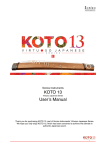
Rear panel graphical representation
2 DVI output port (DVI-D)
Output
DVI1~DVI2
VGA output port
Input
AV1~AV2
VGA
2 CVBS input ports
VGA1~VGA2 2 VGA input ports
DVI input signal loop out port
DVI input port (DVI-D)
DVI Loop
DVI
Expand output port
DP input port
Expand port, RF antenna terminal
Audio output
SDI
HDMI
Customized
Customized, SDI digital audio input
HDMI digital audio input port
Audio
SDI Out
HDMI
7
DP
Expand input port
HDMI input port
E.M.
RF
Multi-machine communication port
Control interface
TX、RX
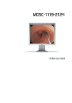
Front panel graphical representation
Hold Knob
Press Knob
MODE
AUTO
PART
PIP
Choose menu items, or adjust parameter
Exit, return to default menu state
Same as the confirm key
exhale template load or save menu
Auto adjust input image position
Shortcut key for part or full
Shortcut key of PIP function
Return
Confirm,or switch browse/setting mode
10 / EFFECT Numeric key 10,Image switch hotkey
9 / E.M.
8 / DP
7 / HDMI
6 / DVI
5 / TAKE
4 / VGA2
3 / VGA1
2 / AV2
1 / AV1
Numeric key 9,E.M. select key
Numeric key 8,DP select key
Numeric key 7,HDMI select key
Numeric key 6,DVI select key
Numeric key 5, Image switch hotkey
Numeric key 4, VGA2 select key
Numeric key 3, VGA1 select key
Numeric key 2, CVBS2 select key
Numeric key 1, CVBS1 select key
Buttons introduction
Anticlockwise
Choose menu items, or adjust parameter
OK
clockwise
8
Technical Specification
Input indicators
Port
AV
VGA
DVI
HDMI
DP
SDI
Number
2
2+1(inherent 2, scalable 1)
1+1(inherent 1, scalable 1)
1
1
1(E.M.)
Resolution
PAL/NTSC
VESA standard
VESA standard (support 1080i input)
EIA/CEA-861 standard,HDMI-1.3
VESA standard
480i、576i、720p、1080i/p(3G SDI)
Output indicators
Port
DVI loop
VGA
DVI
Number
1
1
2
Resolution
In accordance with DVI input, not support HDCP Loop
1024×768/60Hz/75Hz/85Hz/100Hz/120Hz
1280×1024/60Hz
1440×900/60Hz
1680×1050/60Hz
1600×1200/60Hz
1600×1200/60Hz – Reduced
1920×1080/60Hz/50Hz 2560×816/60Hz
2048×640/60Hz
1920×1200/60Hz
2304×1152/60Hz
2048×1152/60Hz
1024×1280/60Hz
1536×1536/60Hz
Customized (bandwidth optimization): H
SDI loop
1
Resolution 3840(max.)
V Resolution 1920(max.)
480i、576i、720p、1080i/p(3G SDI)
General
Power supply
Power consumption
Operating
Cabinet dimension
Net weight
100〜240VAC,50/60Hz
20W
0~45℃
484mm ╳ (288 + 25)mm ╳ (55 + 6)mm
2.6 Kg
9
Using Menu
Unitech Dcdi 550 adopted a high brightness & contrast LCD screen to display the
entire menu system, if the user does not have operation or operation timeout, the
LCD screen will show the default state. Operate the menu system by using the
knob and keys. The user can check and set its function and states convenient and
intuitive to meet the demands.
The following will combine the keys function and the LCD screen display,
detailed introduces you to Unitech Dcdi 550 of menu system.
How to use the keys
The front panel keys of Unitech Dcdi 550 are divided into four areas: MENU,
CONTROL, INPUTS, and TRANSITION. Besides them, there is special
numeric area including all the buttons of INPUTS and TRANSITION area.
MENU area
This area contains a knob which can be pressed, a confirmation key (OK) , and a
return key (
). Press the "knob", its function is same as the confirmation
key; long press the "knob", can make the menu system return to the default state
immediately; when to press return key, the menu system may be back to the
higher level menu in turn until returning to the default state.
In the main menu, OK key is also used in the switching between the two modes
below:
Browse mode
Picture Mode
Brightness
Contrast
Color
Setting mode
Normal
50
50
50
Picture Mode
Brightness
Normal
Contrast
Color
↖ OK key, press the knob, can switch the two modes ↗
10
50
50
50
In the browse mode, anti-clockwise "knob", the cursor moved to the above or the
left. Clockwise "knob", the cursor moved to below or right. Put the cursor to the
item need to adjust, press the "knob", or confirm key, namely into set mode, then
anti-clockwise "knob", can reduce the current parameter value. Clockwise
"knob", it can increase the current parameter values. If you want to continue to
set this page other item, please switch back to browse mode. If you need to
return to the higher level menu, please use the return key. If finish the
adjustment, can long press "knob" to back to the default state directly, or wait for
system overtime, automatic return the default state (in some special interface, the
system will not be back to the default state, for example, image switch fast
interface, user mode fast interface, test picture interface, etc.).
CONTROL area
There are 4 keys: PIP, PART, AUTO and
MODE.
Default menu state
PIP
Other state
Open or close the function of
PIP, if long press the button, it
will change the cascading
relationship between image 1
and image 2 in the permission.
PART
Switch part and full
AUTO
Automatically rectify the
image display position when
the current input source is
VGA.
Mode loading interface,
press AUTO to switch for
mode save interface
MODE
Select the model loading
interface
Mode save interface,press
MODE to switch for mode
loading interface.
11
INPUTS area
In the default menu state, short press the area buttons can switch the image 1
input source to the corresponding input; if long press the button, then can switch
the image 2 input sources to the corresponding input.
In the main menu, when to select the input source interface of image 1 and 2,
short press the area buttons, can set the corresponding menu item parameter to
the corresponding input port.
TRANSITION area
Press "TAKE" or "EFFECT" key, in the default menu system state, can select
image switch interface. In the image switch interface, TAKE key is used to
implement image switch function, EFFECT key is used to select image switch
effect: short press EFFECT key can make the effect parameters positive change,
long press EFFECT, it will make the effect parameters reverse change.
Numeric key area
When browsing the menu, if the current item parameter is for numeric type, can
through ten numeric keys to enter the need values directly. "10" is used to
express the negative number (only in the parameters can be negative) before
entering the numbers. In the edit value process, key "10" is used as "0" input
number zero. In addition, in the edit time or network parameters, can only use
the number keys to type in number directly, and could not set via the "knob".
12
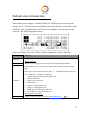
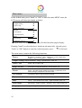
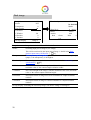
Default state introduction
Turn on the power supply of Unitech Dcdi 550, in the process of the system
startup, the LCD front panel would display the start interface on the left screen,
when the start completed, there will show the machine’s current state on the
screen as the following figure shows:
Above the figure, there are 4 lines content, explanation as the following:
Lines
First line
Second line
Details
Image 1 (main image, is also default image) port name and current input
signal resolution.
Image 2 (vice image) port name and current input signal resolution.
State prompt area, by several icons to show the machine current working
state.
Third line
Fourth line
There are 8 icons areas from left to right: 1、 Synchronism follow-up state
area (valid in the condition of splicing
function opening state) Splicing state area
2、 Mosaic status area
3、 Image freeze state area
4、 PIP state area
5、 Image 1 Cropping state area
6、 Image 3 Cropping state area
7、 PART (part or full screen) state area
8、 DVI input resolution lock state area
Check details in next page.
Output resolution, check details in“Output indicators”[
9]
13
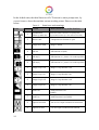
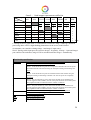
In the default state, the third line area of LCD screen is status prompt area, by
several icons to show the machine current working status. Please see the table
below:
Form 1 : State icons and meanings Icons
14
Area
Name
Hint (shortcut key in the bracket)
1
Synchronism
follow-up state area
When the Mosaic function is in opening state,
Synchronism follow-up is also started successfully
2
Mosaic state
Unequal mosaic function is open
3
Image freeze state
Image is frozen
4
PIP Off
PIP function off (PIP)
4
PIP On[1]
PIP function on,picture 1 is on the top (PIP)
4
PIP On[2]
PIP function on,picture 2 is on the top (PIP)
5
Image Crop 1 Off
Image 1 Crop function is off
5
Image Crop 1 On
Image 1 Crop function is on
6
Image Crop 2 Off
Image 2 Crop function is off
6
Image Crop 2 On
Image 2 Crop function is on
7
PART Off
PART function is off
(PART)
7
PART On
PART function is on (PART)
8
Input lock invalid
Not use DVI input resolution lock function
8
Input lock valid
Use DVI input resolution lock function
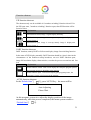
Main menu introduction
The main menu will show the symbols listed in the table below, please check its
specific meaning in the table below:
Symbols Explanation
▶
Press "knob" or "OK" to enter the detail setting page, or operate that directly.
Scroll bar
In the menu, on the right of the LCD screen, there will be a vertical scroll bar
used to say the current option's position in this page, if the scroll bar is located
in the bottom part, the current project is the last menu item of the page.
In the main MENU, the user can use the "KNOB", "OK", "
" and other ten
number key to select and adjust the each item. Its operation is fixed pattern,
please check the following table:
Operation
Key
Open the main menu
Back to default state
Select item
Press "OK" or press "knob" in the default state
Long press "knob"
In the browsing mode, rotate "knob" to select item
Adjust parameters
In the setting mode, rotating "knob" to adjust the selected parameters;
Whether browsing mode or setting mode, numerical parameters can
be set by the number keys.
Enter next level
When there is "▶" on the right of item, press "knob" or "OK"
When there is "▶" on the right of item, press "knob" or "OK"
Performs
Back to higher menu
Confirm
Press “
” key
When the reset operation, to avoid the incorrect operation, need to use
the “OK” key to confirm operation
15
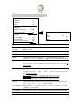
Main menu
In the default state, press "knob" or "OK" to enter the main MENU state, the
LCD screen will show the details as below:
Picture
Output Setting
Video Crop
Image Switching
Mosaic
Test Pattern
Communication
Misc
Dual Image
Language/菜单语言
▶
▶
▶
▶
▶
▶
▶
▶
▶
▶
The main menu has ten sub menu items, divided into three pages display.
Rotating "knob" to select the above listed ten sub menu title, selected, press
"knob" or "OK" button to enter the selected project, press "
" to be back.
The main menu contains the following functions:
Picture
Brightness、Contrast、Color、Sharpness、Color temperature、 Gamma、DVI/VGA Enhance、Scheme, etc.
Output Setting Output Resolution,Image 1 position/Size,Part, etc.
Video Crop
Image 1 & 2, Video Crop
Image Switch
Automatic switch (Hot backup)、Switch Effect, etc.
Mosaic
Image 1 unequal mosaic parameter settings, synchronous lock
mode settings (compatible with old model)
Test Pattern
Test pattern choose, Pixel position locating
Communication Communication setting
Misc
Freeze、Save/Restore user mode、Input resolution Lock, etc.
Dual Image
PIP On/Off、Source Choose、Position、Size、Text overlay, etc.
Language
Support English and Chinese
16
Picture sub menu
Picture Mode
Brightness
Contrast
Color
User
50
50
50
Sharpness
3DNR/VGA Adjust
Scheme
Color Temperature
12
Off/▶
Vivid
▶
Gamma
VGA Enhance
DVI Enhance
Restore Picture Setting
Off
Off
Off
Color Temperature
Red
Green
Blue
Normal
50
50
50
▶
Picture Mode Divided into“User”、“Vivid”、“Soft”、“Normal”the four options.
Brightness
Range 0~100.
Contrast
Range 0~100.
Color
Range 0~100.
Sharpness
Range 0~24.
3DNR
This function is valid when image 1 is not VGA, divided into“Off”、 “Adaptive”、“Low”、“Medium”、“High”the five kinds of denoise mode.
VGA Adjust
It is valid when image 1 is VGA1 or VGA2, automatically to adjust the position and
Scheme
size of input image. This moment, should ensure input image to be full screen and with
a bright edge.
Divided into“Normal”、“Vivid”、“Theatre”、“Game”、“Sport”five modes.
Color Temp
Divided into“Normal”、“ Warm”、“ Cool”、“User”the four options.
Only when select“User”,“ Red”、“ Green”、“ Blue” the three options is effect
and the range is 0 to 100.
Gamma
Red
Green
Range 0~100,Valid in the Color Temp is set to “User”.
Range 0~100,Valid in the Color Temp is set to “User”.
Blue
Range 0~100,Valid in the Color Temp is set to “User”.
Control the output Gamma value of video processor, divided into“Off”、 “2.0”、“2.2”、“2.8”、“-1.1”、“-1.2”six options.
VGA Enhance Divided into“Off”、“Level0”、“Level1”、“Level2”、“Level3”、“Level4”、 “Adaptive”seven options.
DVI Enhance
In state of DVI input, it can greatly improve the output color and clarity.
Restore Pic.
Reset above all the parameters to be the default value.
17
Output Setting sub menu
Output Resolution
H Window
V Window
H Position
V Position
Part Or Full
▶
1024
768
0
0
Full
Output To
1024×768 60Hz
Press OK to Confirm
H Resolution
V Resolution
Output Rate
Apply
1344
576
60
▶
Output
Resolution
Unitech Dcdi 550 support 19 kinds of regular output resolution, also can
customize horizontal/vertical parameter of output resolution. Use the knob to
choose the resolution that needs to be set, press knob or ok to finish the settings. If
choose "customize", need to set the resolution furthermore, then choose "apply"
to finish. Find details in“output indicators”[
9]。
H Window Minimum 64,Maximum is“the width of the current output resolution”.
V Window Minimum 48,Maximum is “the height of the current output resolution”.
H Position Minimum -16,the biggest can be set to the differentials between“the width
of the current output resolution”and“H Window”.
V Position
Minimum -16,the biggest can be set to the differentials between“the height
of the current output resolution”and“V Window”.
Part
Or
Full
Full:namely PART function shut.
Now the complete image will be shown on the LED screen, and the monitor will
display shrunken image, "H Window" , "V Window" , "H Position" and "V
Position" four parameters take effect automatically.
Part:namely PART function open.
At this time the LED screen will show a part of the image, and the monitor will
display full screen image, "H Window" , "V Window" , "H Position" and "V
Position" four parameters will to be void.
Please set the output resolution, H width and V height based on the physical resolution of
LED screen. If do not have suitable output resolution, please select the options with bigger
resolution than the reality. Or to choose the customize output resolution, to connect with
the LED screen pixel to pixel directly.
When it is smaller LED screen, suggest using regular output resolution, conversely, if the
aspect ratio is very big, or the aspect ratio is very small, suggest using customized
18
output resolution.
Note1: please use the bigger than 60Hz refresh rate or greater height
and width pixel output resolution judiciously, it is not sure that the back-end
equipment can support this resolution.
Note 2: customized output resolution is not the standard output signal,
part of the monitor may not be able to identify, but does not affect the LED
display, please use carefully.
19
Video Crop sub menu
Image 1 Video Crop
Image 2 Video Crop
Image 2 Crop
Width
Height
H Start
▶
Off
1024
768
0
V Start
Reset Image 2 Crop
Image 1/2 Crop
▶
Image 1 Crop
Width
Height
H Start
Off
1024
768
0
V Start
Reset Image 1 Crop
0
▶
0
▶
“On” or “Off” the Video Crop function for Image 1/2, default is Off
Width
Minimum value is 64, maximum value is the "input signal width"
Height
Minimum value is 32, maximum value is the "input signal height".
H Start
Minimum value is 0, the biggest can be set to the differentials between
“input signal width”and“Width”.
V Start
Minimum value is 0, the biggest can be set to the differentials between
“input signal height”and“Height”.
Reset
Reset the above four parameters.
Unitech Dcdi 550 support dual image video crop.
Image 1 Crop function only can be used in "Image 1 mosaic" closed, and Image
1 input signal effective. Image 2 Crop only can be used in Image 2 input signal
effective. If “Video Crop” could not be used, system will give some hints when
entering the submenu, users can exit this function according to the prompt , or
force into the Video Crop interface (force into will close the conflict function).
Additional remarks: input signal width, height and other information can be
checked in the display of "current input signal resolution specifications" in the
state of“Default State”[
20
13] .
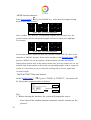
Image Switching sub men
Auto Switch
Switch Mode
Take
Auto
Switch
Off
Cut
▶
Off
1 VGA1
1280╳1024 60Hz
TAKE
━━━━━━━━━━
2
DVI
Cut
1920╳1080 60Hz
EFFECT
Auto switch function is closed.
Window1 If the image 1 input signal effective, the image 1 is on the top.
Window2 If the image 2 input signal effective, the image 2 is on the top.
Signal*
The effect input signal picture is on the top.
Switch Mode 20 kinds of switch mode.
Take**
From this to enter the image switch shortcut interface (will force to close the
auto switch function).
* :Signal priority options, used when the two picture input signals is invalid, the first effective
picture is located in the top, the next effective picture will no longer make the layer change.
**:All the operation could be accomplished in the shortcut menu of the picture switching. As
the above the right shows, the first interface is the input port of image 1 and input signal prompt;
The third line is image 2 input port and input signal prompt; The second line is separator and
switch button prompt ("TAKE" button, it will be the same effect to press "OK" and "TAKE" in
the interface); The fourth line is a switch mode information, the left character is used to display
the current switching mode, the right is the key prompt ("EFFECT" key), to short press
"EFFECT" key, switching mode will change as the forward direction, long press "EFFECT"
key, switch mode will change as the reverse direction.
In the fast switching interface, can use the INPUTS key to switch the bottom
layer picture(the un-highlighted picture of the interface) input port, when it
shows the effective format of the input signal, to press "TAKE" can display the
input signal on the top in seamless switching.
Note: if the bottom picture input signal is invalid, advise to use the "Cut" and
"Fade" effect, and press the "TAKE", the invalid signal will be switched to the
top shows at the form of blank screen.
21
Form 2 : Switching Mode list L+T Pop-up1
R+B Pop-up1
Bot Pop-up1
L+T Pop-up2
R+B Pop-up2
Bot Pop-up2
L+B Pop-up1
Center Pop-up1
Left Pop-up1
L+B Pop-up2
Center Pop-up2
Left Pop-up2
R+T Pop-up1
Top Pop-up1
Right Pop-up1
R+T Pop-up2
Top Pop-up2
Right Pop-up2
Note 1:
the occurring image
Note 2:
the disappearing image
Note 3: Arrow means its moving direction in the image edge, that is, where
the arrow image is compressing or stretching indicated by the arrow direction
until disappeared or full screen.
22
Mosaic sub menu
Image 1 Mosaic
H Total
V Total
Width
Height
H Start
V Start
Sync Mode
Off
1536
640
768
320
0
0
Mode1
Image 1 Mosaic
Image 1 mosaic function “On” or “Off”, default is Off.
H Total
The physical pixel points of the LED screen in horizontal direction.
V Total
The physical pixel points of the LED screen in vertical direction.
Width
The pixel points that the display area of the current video processor
shown in the horizontal direction.
Height
The pixel points that the display area of the current video processor
shown in the vertical direction.
H Start
The level starting position of the display area that controlled by the
current video processor.
V Start
Sync Mode
The LED screen top-left corner is viewed as the original point (horizontal
starting point 0).
The vertical starting position of the display area that controlled by the
current video processor.
The LED screen top-left corner is viewed as the original point (vertical
starting point 0).
Divided into "mode1" and "mode2," mode1 for compatibility mode,
used to connect with the old model for splicing.
Note: the detailed mosaic setting explanation, please refer to the "Unequal
Mosaic” [ 35]。
23
Test Pattern sub menu
Test Pattern
H Locating
V Locating
Test
Pattern
0
-1
-1
Range 0~72. 0 means no test pattern display,1~72 means test pattern number.
Open test picture, will close the image 2 by force.
If there is no signal for the image 1 input port, it will be displayed as
"Unavailable"
H
Locating*
V
Locating*
The valid range minimum value is 0; maximum value is the horizontal width of
the current output resolution.
To determine the horizontal position of the cursor on the screen, "-1", close the
cursor.
The valid range minimum value is 0, maximum value is the vertical height of the
current output resolution.
To determine the vertical position of the cursor on the screen, "-1", close the
cursor.
*: "H position" and "vertical position", as long as there is a numerical for "-1", in the picture
will not display the positioning cursor.
24
Communication sub men
Mode
USB Mode
Network Config
DHCP
IP Address
Subnet Mask
Gateway
Mode
USB
Mode
USB
Manual
▶
Auto
192.168.1.100
255.255.255.0
192.168.1.1
▶
DNS Config ▶ MAC
AABB-CC-DD-EE-FF Save Network
Config
▶
Restore Network Config
▶
DNS Mode
Auto DNS
192.168.1.1
USB
Connect the USB of the front panel to PC computer, and
operating the machine through the PC software.
Network*
Connect the machine to a LAN, through the web browser to
operate the machine directly.
Multi Processor
Connect several LED550 together with communication line,
to achieve multi machine interconnected.
Manual
Connect the machine to the computer through the USB,
Auto
Network
Config*
IP Config
need to set the mode to be USB manually, then can control the
machine through the PC software.
Through the USB to connect the machine to the computer,
can through the PC software to control the machine.
IP Config
Set the IP address and other related parameter.
DNS Config
Set DNS parameter.
MAC
Show MAC of local processor.
Save
Network
Config
Used for preserve the change of network parameters before, if
exit the interface without saving, it means to give up.
Restore Network
Config
Reset the network parameters to be the default Settings.
*: Unitech Dcdi 550 series video processor, not each model is provided with network
module, without network module, it will show the network relevant settings interface.
25
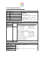
Misc sub menu
Freeze
Save Mode
Restore Mode
Lock Input Resolution
Menu Timer
HDMI Crop.
DVI Any Mode
Factory Reset
Input Resolution
Apply Lock Process
Restore Default
Matching Method
H Resolution
V Resolution
Off
▶
▶
▶
Save
Template1
Press OK to Confirm
30S
Off
Off
▶
Restore
Template1
Press OK to Confirm
▶
▶
▶
Factory Reset
Press<OK>to Continue
Press<RETURN>to Cancel
Manual
1344
576
Freeze
Freeze functional switch, the picture display normal when it is closed, and
be still when it is open.
Save Mode
Save the current user settings. Can save 10 templates at the most.
Restore Mode
Restore the before settings from template.
Lock Input
Resolution*
Matching Method “Manual”or“Auto**”. if auto is set, system can
read the configuration from back-end.
H Resolution
Hand configuration output resolution horizontal
locking value of the front end equipment.
V Resolution
Hand configuration output resolution vertical
locking value of the front end equipment.
Apply Lock
Apply the above setting to the system.
Restore Default
Restore the above parameters to be the default
value.
Menu Timer
Without any operation, the menu system will be back to the default state
time. The default value is "30S", can be set to "60S" or "10S".
HDMI Crop.
HDMI reproduce rate setting, the default is closed.
DVI Any Mode
DVI arbitrary mode setting, the default is closed.
Factory Reset
Restore all settings to default.
26
*: Input resolution lock function is just effective for DVI input, if the lock resolution is not a
standard resolution, that will require the front end DVI signal source with any model
output functions (for example the computer with DVI output).
**: In the automatic matching mode, the machine will only through the DVI1 output port to
detect the properties of the back end equipment automatically, which automatically gets
the best input resolution of the back end equipment. Therefore, if you need to use
automatic matching mode, please use the DVI1 output port.
27
Dual image
Image 2
Source
Transparent
Text Overlay
Off
DVI
0
▶
H Window
V Window
H Position
V Position
1024
768
0
0
On Top Display
Text Overlay
Off Preset
User Blend Mode
Mode1
Blend level
Below
And/Or
Red
Green
0 0
0 Above/
Above
And
Blue
0
Image 2
Image 2
Image 2’s“On”and“Off”, default is Off.
Source
Switching input port of image 2(vice image)
Transparent
This will be restricted by the input port of image 1, details in the“Dual
pictures input source conflict list” [
29].
The transparency of image 2, range is 0~3, when the value is 0, completely
opaque, 3 the transparency is the highest.
Text Overlay
Text overlay, cutout synthesis menu, check details in the “text overlay
specification” [
29].
H Window
The horizontal width of the image 2, and the minimum value is 64,
maximum value is "the current output resolution width".
V Window
The vertical height of the image 2, and the minimum value is 48, maximum
value is "the current output resolution height"
H Position
The top-left corner of image 2 levels of coordinates in "output resolution
window".
V Position
The top-left corner of image 2 vertical coordinates in "output resolution
window".
On Top Display Switching the current top image; can choose "Image 1"or"Image 2".
28
Form 3 : Dual images input source conflict list Image1
Image2
AV1
AV1
AV2
"
AV2
VGA1
╳
" *
" *
" *
" *
" *
" *
"
" *
" *
" *
" *
" *
" *
"
"
"
"
"
"
"
"
"
╳
VGA2
VGA1
"
"
VGA2
"
"
DVI
"
"
"
"
HDMI
"
"
"
"
DP
"
"
"
"
E.M.
"
"
"
"
╳
DVI
╳
HDMI
DP
"
╳
"
"
"
"
"
"
"
"
╳
E.M.
"
"
"
"
"
"
Note
1: During the above graph with "*" combinations, because the image 2 didn't go interlaced
processing, there will be a slight shaking phenomenon in the screen, in this kind of
circumstance, can consider exchange image 1 and image 2 input source.
Note 2: During switch input port, the system to image 1 for priority, if image 2 port and image 1
port conflict with each other, image 2 will be switched under the image 1 automatically.
Text Overlay specification
text overlay
Blend Mode
Text overlay function "Open" and "Closed". The default is closed.
Divided into "Mode1"and"Mode2" two patterns.
Mode1:In this mode the text pixels are on top and not blended. The non-text pixels
are blended with the other channel using the Transparent setting in Dual Image sub
Menu.
Above/Below
And/Or
Red
Green
Blue
Mode2:In this mode the text pixels are blended with the other channel using the
Transparent setting in Dual Image sub Menu. The non-text pixels are completely
transparent.
Above:The pixel that has any color value above the Red, Green and Blue level
become tagged as TEXT PIXELS, the rest of the pixels becomes NON-TEXT pixels.
The judgment should be combined with the "And/Or" conditions.
Below:The pixel that has any color value below the Red, Green and Blue level
become tagged as TEXT PIXELS, the rest of the pixels becomes NON-TEXT pixels.
The judgment should be combined with the "And/Or" conditions.
And:all three color must be used to trigger the above / below comparison
Or:any color is enough to trigger the above / below comparison
Red Threshold, Range: 0~255
Green Threshold, Range: 0~255
Blue Threshold, Range: 0~255
29
Language sub men
Language Select
文/Chinese
English/英文
中
中文/Chinese
the menu will display in Chinese
English/英文
the menu will display in English
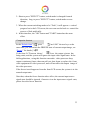
Shortcuts menu
Unitech Dcdi 550 sets up total eight input shortcuts (INPUTS), four function
shortcuts (CONTROL), and two picture switch shortcuts (TRANSITION). Input
shortcuts are:“AV1”,“AV2” ,“VGA1”,“VGA2”,“DVI”,“ HDMI”、 DP” and
“E.M.” respectively; Function shortcuts
are:“PIP”,“PART”,“AUTO”,“MODE”and Switch shortcuts
are“TAKE”and“EFFECT”.
All
the name of the keys and its position of the machine, please refer to the
“Front panel graphical representation”[ 8]。 Note: Unless specifically
mentioned otherwise, all shortcut keys are not effective unless in the "default
state".
Input shortcut
In the default state, to any input shortcuts, image 1 signal input port will switch
directly to the input port which is corresponding with the input shortcuts.
Moments later, the menu system will show the input channel state, including port
name, whether the input signal is effective or not, also will show signal resolution
specifications in effective case. About this content, please refer to the“Default
state introduction”[ 13]。
If users need to switch image 2 port, can long press the relevant input shortcut
in the default state, if it is not conflict with the image 1 input port, the input port
of image 2 will be switch to target port directly; Otherwise, will pop up prompt
window, users can cancel operation or forced switching two pictures input port
as demands.
30
Function shortcut
PIP function shortcut:
The shortcuts only can be available in "seamless switching" function closed. If in
the PIP open state, "seamless switching" function open, then PIP function will be
forced to close.
Icon
Explanation
PIP function closed, image 1 signal display normally.
PIP function open, image 1 is on top, namely image 1 display area
covers image 2.
PIP function open, image 2 is on top, namely image 2 display area
covers image 1.
PART function shortcut:
PART function, namely PART or full-screen display image fast switching function.
In the state of LED display normally, PART function should be closed; when in the
circumstance of the monitor to setup broadcast, can use PART function open,
image full resolution display characteristics, to make the process convenient and fast.
Icon
Explanation
PART function closed. LED screen display the complete program picture,
the program picture is shrinking in the monitor.
PART function open. LED screen display part program picture, the
programs’ picture is full screen in the monitor.
AUTO function shortcut:
In the“Default State”[
13], press“AUTO”key,the menu will be:
Auto Adjusting
Please Wait . . .
At this moment, system is to adjust the display position of the image
automatically, after this process completed, the menu system returns to
“Default State”[
13].
31
MODE function shortcut:
In the“Default State”[
13], press“MODE”key,menu enter the template loading
shortcut menu state as below:
1
2
3
4
5
6
7
8
9
10
Num. Key To Load Templates
Press a number key, then the corresponding template will be loaded into the
system instantly, and the corresponding digital will also be displayed in highlight.
For example:
1
2
3
4
5
6
7
8
9
10
Num. Key To Load Templates
In the multi-machine connection state, any one unit Unitech Dcdi 550 can be as the
controller of "MODE" function. Ensure all the machines in the“Default State”[ 13],
press the "MODE" key on any machine, all the machines will enter the template
loading shortcut menu state, in this shortcut menu state, press any numeric key on any
machine, then all the machine will load the corresponding template of their respective
system, it is convenient for you to switch the working state in various application
occasions rapidly.
TAKE & EFFECT function shortcut:
In the“Default State”[
13], press "TAKE" or "EFFECT",the menu will
be fast picture switch interface as belows:
1 VGA1
1280╳1024 60Hz
TAKE
━━━━━━━━━━
2
DVI
Cut
1920╳1080 60Hz
EFFECT
Tips:
1. Before entering the interface, the system will prompt the user to
force close all the conflict function (automatic switch), and turn on the
picture 2.
32
2. Short to press "EFFECT" button, switch mode is changed forward
direction; long to press "EFFECT" button, switch mode reverse
change.
3. When the current switching mode to be "Fade", it will appear a vertical
progress bar in the LCD screen, the user can use the knob to control the
process of fade artificially.
4. In this interface, the "OK" button and "TAKE" button has the same
effect.
Composite shortcut
In the“Default State”[ 13], press “
”and “OK” the two keys at the
same time, you can switch the FREEZE state of current output image, see
“Freeze” for details [ 26].
If the front LCD screen shows“
”icon, the output picture has
being static, and the system will ignore the input video signal state. In the
field applications, using this function can make video processor keep
output a stationary frame, then can pull out, shut down or replace the front
video equipment of video processor, and will not affect the output image of
the video processor.
If the freeze icon disappears from the front LCD screen, the system is in the
normal output state.
Note that, when the freeze function takes effect, the current input source
signal state should be ignored, if want to view the input source signal state,
please close the freeze function.
33
Using Mosaic
Mosaic summarize
Unitech Dcdi 550 single has two send card slots, two cards can convey the same
image for the two LED display at the same time, also can use two cards
cascading, and increase the load area for conveying HD image to a high
resolution LED display.
If the actual pixel of the LED display beyond of the sending cards loading
ability, for this kind of circumstance, need to use more than one sending cards
and use video processor splicing function to solve. Adopt processor splicing,
namely can use multi machine combing to display the complete image, also can
display independent image separately.
Video processor Unitech Dcdi 550 using "synchronous follow-up" technology,
solved the difficult splicing problem: splicing image motion lacerate
phenomenon, namely the phenomenon of the moving pictures dislocated in
splicing crossing. "Synchronous follow-up" technology lets users easily use the
LED video processor to realize the large LED screen splicing. "Synchronous
follow-up" function will open in the state of splicing function open, the menu
system will give the current video synchronism state tips, about this part of the
content, please refer to the“State icons and meanings” [ 14].
Video processor Unitech Dcdi 550 provides“unequal mosaic”, just need to
confirm the display area and location in the whole LED screen for each unit, then
can realize the perfect splicing.
Following is the detailed Unitech Dcdi 550 splicing function using introduction
and the matters needing attention.
34
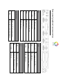
Unequal Mosaic
Unequal Mosaic is applicable to all need splicing occasions, equal splicing is the
special case of the unequal splicing, namely is the special situation of all splicing
unit parameters are the same. For all the occasions besides that, all can use
unequal joining function.
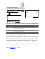
Following is the example to illustrate how to set the unequal splicing
parameters. Splicing form is as below:
384(Pixel)
288(Pixel)
No. 1
No. 2
No. 3
No. 4
576(Pixel)
384(Pixel)
In this case there are four groups LED display screens, each group need a
Unitech Dcdi 550. The four machines unequal splicing parameters must be set
as the following table:
Processor
Parameter
No. 1
No. 2
No. 3
No. 4
H Total
960
960
960
672
672
960
V Total
672
0
576
0
0
0
384
576
384
576
384
384
288
H Start
V Start
Width
Height
672
576
384
384
288
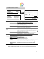
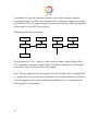
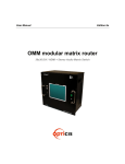
After finished the system constructing, need to test the splicing effect, if
35
"synchronous follow-up" function cannot be successfully launched (namely
synchronous follow-up icon are not displayed for a long time), then need to add a
Unitech Dcdi 550 to do signal shaping, and the above four sets LED can share the
plastic signal by itself DVI loop out port
Following is the system diagram:
LED
LED
LED
LED
Dcdi 550
Dcdi 550
Dcdi 550
Dcdi 550
Dcdi 550
The diagram above, No. 1 and No. 4 the four sets of input signal Unitech Dcdi
550 completely consistent. Unitech Dcdi 550 supports infinite level DVI signal
connecting loop out without DVI signal splitter.
Note: The description for the pixel position of Unitech Dcdi 550, is starting from
0, namely the top-left corner pixels horizontal and vertical positions are both for
0, increasing from left to right on the horizontal direction, on vertical direction
increasing from top to bottom.
36
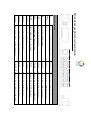
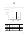
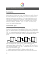
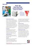
How to realize the splicing between different dot pitch? For instance:
P6
P6
P6
P9
P9
100×100
100×100
100×100
100×100
100×100
P6
P6
P6
100×100
100×100
100×100
P9
P9
P6
P6
P6
100×100
100×100
100×100
100×100
100×100
Above LED screen, joint by two LED screen with different dot pitch, on the exterior,
formed a whole unit; the P6 screen on the left, dot matrix for 300×300; The right P9
screen, dot matrix for 200×200.
Now we use two video processors to realize splicing, supposed the left side using the No.
1 processor, the right to use the No. 2 processor, the splicing parameters should be set as
following:
Processor
Parameter
No. 1
No. 2
H Total
3600
3600
V Total
1800
H Start
V Start
Width
Height
0
0
1800
1800
1800
1800
0
1800
1800
Computational formula:
H Total = the sum of each dot pitch of LED in horizontal direction multiply the
horizontal pixels of LED screen.
V Total = the sum of each dot pitch of LED in vertical direction multiply the vertical
pixels of LED screen.
Width = dot pitch × screen horizontal pixels
Height = dot pitch × screen vertical pixels
37
Multi machine connection
Summarize
With the large area, HD display time arriving, the LED display area usually will beyond
the sending card loaded area more, LED display project also is to realize by the way of
using many screens and processors. However, with the increasing of the processors, let
field control staff’s work also become complicated. For that, simplified site operation,
Unitech Dcdi 550 has multi-machine connection function. Multi-machine connection
function is as following: all machines recover to a certain work mode quickly,
namely "multi-machine loading template".
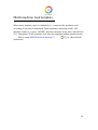
Connection type
On the left of the rear panel of Unitech Dcdi 550, there are two 3.5 mm headset
jacks, one marked as "TX" for the communications signals sent port; another is
"RX" as a communication signal receiver port. In order to achieve multi machine
connection, we need to connect all the machines according to the following
picture.
TX
TX
TX
TX
RX
RX
RX
RX
In the above diagram, the arrows represent 3.5 mm headset plug, and
communication signals are always from "TX" port sent to "RX" port. This is a
cyclic annular, its advantage is: A. Any of Unitech Dcdi 550 can be a starting
point of the communication signal,
namely operating terminal can be arbitrary machine of the ring.
B. Easily to add or remove one unit machine from the circular link structure.
38
Multi machine load template
When many machine state is established (i.e. connected the machines well
according to the above mentioned "Multi machine connection mode" will
machine connect), to press "MODE" function shortcuts in any one Unitech Dcdi
550 front panel, all the machines will enter the template loading shortcut menu.
Please return“MODE function shortcuts”[
32] to check details
instruction.
39
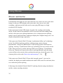
Input signal hot backup
Summarize
Note that what the input signal hot backup is? What is the use of it?
In simple terms, warm backup is that when the input signal missed, using spare
input signal automatically and rapidly to replace the original input signal,
maximum ensure output image uninterrupted.
Hot backup is a powerful guarantee to the stability of the system, which makes
the impact to be the lowest that made by signal input device failure.
How to use the hot backup?
Enter the "PIP submenu" and select "automatic switching function", you can set
how to use Unitech Dcdi 550 hot backup function here. Here are four options, for
details please refer to the table below:
Item
Details
Off
Not to use the heat backup function
Window 1
If image 1 signal is valid, then output image 1,
otherwise, output image 2.
Window 2
If image 2 signal is valid, then output image 2,
otherwise, output image 1.
Signal
In the case of two channels signal are invalid, the first
valid of the two channels signal, then its image will be
output, the behind signal does not affect the output.
Note that when you use the hot backup function, location and size of image 1 or
image 2 output screens should be set in advance according to actual use.
40
Recommend using "Window 1" option, set the backup sources to the image 2.
Hot backup is the operation based on the signal detection, when the signal source
is unstable or lost moments, there will be instant black screen, but within the
fastest time (around 0.2 seconds), backup channel image will be displayed, let
picture interrupt time reduced to a minimum.
41
FAQ
Unitech Dcdi 550 provides abundant function for the customers, some functions use
requires users to have quite a bit of professional knowledge. When you have problems, can
try to timing machines, if cannot solve it according the following step, please contact with
the local agent, or contact our service department directly. For your safety, do not attempt
to repair the product by yourself.
Phenomenon
No output image and no
display on LCD in the front
panel.
LCD in the front panel is
displaying information, but
no output image or the image
is not stable
Check list
! Check the power cord
! Check the power switch
! Check whether properly connected the input signal and
!
!
!
!
!
Image display position
deviation
VGA or DVI port images
showed abnormal
VGA Image displayed in
un-full screen
PIP display abnormal
Fade function is invalid
42
Page
have switched to the corresponding source (if no signal, the
front panel LCD screen will display no signal, and the
machine will have no image output at the moment)
Check display terminals whether to support the output
resolution and refresh rate of Unitech Dcdi 550.
Check if the brightness and contrast set too low.
Check whether the user color temperature set too low.
check image 1 and 2 input status, whether the top picture
showed a signal
Try to reset the machine to be the factory setting by
"factory reset" of the "function Settings" sub menu.
! Enter "output Settings" submenu, adjust the "horizontal
position" and "vertical position", till the image display
properly
! Check whether the input signal resolution is accordance
with VESA standard.
! Press the front panel "AUTO" button until the image
display correct (automatic adjustment, please use the full
screen and not take black side signal)
! Check if it is reasonable that the item numerical of
"horizontal width" and "vertical height”, "horizontal
position" and "vertical position" of "PIP" submenu.
! Check whether automatically switch function is closed
! Whether the input signal of image 1 and image 2 is valid.
[
13]
[
9]
[
17]
[
17]
[
13]
[
26]
[
18]
[
9]
[
8]
[
31]
[
28]
[
21]
[
13]
Model Introduction
Unitech Dcdi
550S
S SDI input/loop out
D Expand external DVI input port
V Expand external VGA input port
Warranty
The whole unit warranty
! One year (from the buying date);
! If the invoice is lost, the 60 days after the production date will be the
warranty start date for the product.
The warranty provisions
! The machine soaking and collisions produced besmirch or surface
!
!
!
!
scratches and other abnormal using causes of malfunction or damage;
Demolition machine or modification, which is not to be agreed by our
company;
Using in the not specified used working conditions, resulting in fault or
damage (such as high temperature, low voltage or unstable etc.);
Force majeure (such as fire, earthquake, etc.) or natural disasters (like
lightning, etc) caused the fault or damage;
Beyond the product warranty.
43