1
Agilent 75000 Series
Installing SCPI Device Drivers
Installation Note
Important
If you are using Windows®* and an external PC, we recommend that you use Agilent
VIC to install drivers. Agilent VIC is a Windows 3.1 VXI hardware installation
program. The program helps you configure and install VXI instruments and can also
download MS-DOS®*-formatted instrument drivers. Using Agilent VIC to download
drivers is easier and faster than using the procedures described in this installation note.
Agilent VIC downloads drivers during the configuration process and stores a copy of the
driver in the C:\VIC\DRIVERS directory the FIRST TIME the instrument is configured.
If you are updating an already installed driver, the new driver can be downloaded using
Agilent VIC’s Driver Download utility. Instructions for using Agilent VIC and its Driver
Download utility are contained in the software’s online help. Agilent VIC ships with the
Agilent E1306/E1406 Command Modules and the Agilent E1300/E1301 mainframes.
*Windows® and MS-DOS® are U.S. registered trademarks of Microsoft Corporation.
Copyright© Agilent Technologies, Inc., 1996 - 2006
*E1401-90022*
Manual Part Number: E1401-90022
Printed in Malaysia E0506
AGILENT TECHNOLOGIES, INC. SOFTWARE LICENSE TERMS
ATTENTION: USE OF THE SOFTWARE IS SUBJECT TO THE LICENSE TERMS SET FORTH BELOW.
IF YOU DO NOT AGREE TO THESE LICENSE TERMS, THEN (A) DO NOT INSTALL OR USE THE SOFTWARE, AND (B)
YOU MAY RETURN THE SOFTWARE FOR A FULL REFUND, OR, IF THE SOFTWARE IS SUPPLIED AS PART OF ANOTHER
PRODUCT, YOU MAY RETURN THE ENTIRE PRODUCT FOR A FULL REFUND. NOTWITHSTANDING ANYTHING TO THE
CONTRARY IN THIS NOTICE, INSTALLING OR OTHERWISE USING THE SOFTWARE INDICATES YOUR ACCEPTANCE
OF THESE TERMS.
AGILENT SOFTWARE LICENSE TERMS
Software. "Software" means one or more computer programs in object code format, whether stand-alone or bundled with other products,
and related documentation.
License Grant. Agilent grants you a non-exclusive license to use one copy of the Software for internal purposes in accordance with
these License Terms and the documentation provided with the Software. Such documentation may include license terms provided by
Agilent’s third party suppliers, which will apply to the use of the Software and take precedence over these License Terms. In the absence
of documentation specifying the applicable license, you may use one copy of the Software on one machine or instrument. If the software
is licensed for concurrent or network use, you may not allow more than the maximum number of authorized users to access and use the
software concurrently.
License Restrictions. You may make copies or adaptations of the Software only for archival purposes or only when copying or
adaptation is an essential step in the authorized use of the Software. You must reproduce all copyright notices in the original Software on
all permitted copies or adaptations. You may not copy the Software onto any public or distributed network.
Upgrades. This license does not entitle you to receive upgrades, updates or technical support. Such services may be purchased
separately.
Ownership. The Software and all copies thereof are owned and copyrighted by Agilent or its third party suppliers. Agilent and its third
party suppliers retain all right, title and interest in the Software. Agilent’s third party suppliers may protect their rights in the Software in
the event of any violation of these License Terms.
No Disassembly. You may not disassemble or otherwise modify the Software without written authorization from Agilent, except as
permitted by law. Upon request, you will provide Agilent with reasonably detailed information regarding any permitted disassembly or
modification.
High Risk Activities. The Software is not specifically designed, manufactured or intended for use in the planning, construction,
maintenance or direct operation of a nuclear facility, nor for use in on line control or fail safe operation of aircraft navigation, control or
communication systems, weapon systems or direct life support systems.
Transfer. You may transfer the license granted to you here provided that you deliver all copies of the Software to the transferee along
with these License Terms and pay any applicable fees to the extent permissible under local laws. The transferee must accept these
License Terms as a condition to any transfer. Your license to use the Software will terminate upon transfer.
Termination. Agilent may terminate your license upon notice for breach of these License Terms. Upon termination, you must
immediately destroy all copies of the Software.
Export Requirements. If you export, re-export or import Software, technology or technical data licensed hereunder, you assume
responsibility for complying with applicable laws and regulations and for obtaining required export and import authorizations. Agilent
may terminate this license immediately if you are in violation of any applicable laws or regulations.
U.S. Government Restricted Rights. Software and technical data rights granted to the federal government include only those rights
customarily provided to end user customers. Agilent provides this customary commercial license in Software and technical data pursuant
to FAR 12.211 (Technical Data) and 12.212 (Computer Software) and, for the Department of Defense, DFARS 252.227-7015 (Technical
Data - Commercial Items) and DFARS 227.7202-3 (Rights in Commercial Computer Software or Computer Software Documentation).
Installing SCPI Device Drivers 3
Table of Contents
Getting Started . . . . . . . . . . . . . . . . . . . . . . . . . . . . . . . . . . . . . . . . . . 5
Device Driver Installation Kit Contents . . . . . . . . . . . . . . . . . . . . . . . . . . . . 5
Special E1406 Capabilities . . . . . . . . . . . . . . . . . . . . . . . . . . . . . . . . . . . 6
Driver RAM Configuration . . . . . . . . . . . . . . . . . . . . . . . . . . . . . . . . . . 7
Setting System Configuration . . . . . . . . . . . . . . . . . . . . . . . . . . . . . . . . . . 8
Default Configuration . . . . . . . . . . . . . . . . . . . . . . . . . . . . . . . . . . . . . 8
Editing the Configuration File . . . . . . . . . . . . . . . . . . . . . . . . . . . . . . . . . 8
Standard Device Driver Installation . . . . . . . . . . . . . . . . . . . . . . . . . . . . . . . 10
Installing from a BASIC (programming language) System
System Setup . . . . . . . . . . . . . . . . . . . . .
Procedure . . . . . . . . . . . . . . . . . . . . . . .
Installing Device Drivers from MS-DOS . . . . . . . . .
System Setup . . . . . . . . . . . . . . . . . . . . .
Procedure . . . . . . . . . . . . . . . . . . . . . . .
Installing from IBASIC . . . . . . . . . . . . . . . . . .
System Setup . . . . . . . . . . . . . . . . . . . . .
Procedure . . . . . . . . . . . . . . . . . . . . . . .
.
.
.
.
.
.
.
.
.
.
.
.
.
.
.
.
.
.
.
.
.
.
.
.
.
.
.
.
.
.
.
.
.
.
.
.
.
.
.
.
.
.
.
.
.
.
.
.
.
.
.
.
.
.
.
.
.
.
.
.
.
.
.
.
.
.
.
.
.
.
.
.
.
.
.
.
.
.
.
.
.
.
.
.
.
.
.
.
.
.
.
.
.
.
.
.
.
.
.
.
.
.
.
.
.
.
.
.
.
.
.
.
.
.
.
.
.
.
.
.
.
.
.
.
.
.
.
.
.
.
.
.
.
.
.
.
.
.
.
.
.
.
.
.
.
.
.
.
.
.
.
.
.
.
.
.
.
.
.
.
.
.
10
10
11
11
11
11
12
12
12
Manual Device Driver Installation . . . . . . . . . . . . . . . . . . . . . . . . . . . . . . . 13
Installing Over GPIB . . . . . . . . . . . . . . . . . . . . . . . .
System Setup . . . . . . . . . . . . . . . . . . . . . . . . .
Procedure . . . . . . . . . . . . . . . . . . . . . . . . . . .
Installing Over RS-232 . . . . . . . . . . . . . . . . . . . . . . .
Transmission Format . . . . . . . . . . . . . . . . . . . . .
Pacing the Data . . . . . . . . . . . . . . . . . . . . . . . .
Procedure . . . . . . . . . . . . . . . . . . . . . . . . . . .
Transferring Device Drivers Using a COPY Command
Transferring Device Drivers Using a CAT Command .
Transferring Device Drivers Using Custom Software .
4 Table of Contents - Installing SCPI Device Drivers
.
.
.
.
.
.
.
.
.
.
.
.
.
.
.
.
.
.
.
.
.
.
.
.
.
.
.
.
.
.
.
.
.
.
.
.
.
.
.
.
.
.
.
.
.
.
.
.
.
.
.
.
.
.
.
.
.
.
.
.
.
.
.
.
.
.
.
.
.
.
.
.
.
.
.
.
.
.
.
.
.
.
.
.
.
.
.
.
.
.
.
.
.
.
.
.
.
.
.
.
.
.
.
.
.
.
.
.
.
.
.
.
.
.
.
.
.
.
.
.
.
.
.
.
.
.
.
.
.
.
.
.
.
.
.
.
.
.
.
.
13
13
13
14
14
14
15
16
16
17
Installing SCPI Device Drivers
Getting Started
This note describes how to install SCPI device drivers into these products:
•
•
•
•
Agilent E1300/1301 B-Size Mainframe (with built-in Command Module)
Agilent E1306 B-Size Command Module
Agilent E1405A/B C-Size Command Module
Agilent E1406A C-Size Command Module
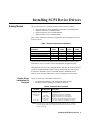
Table 1 shows installation combinations supported by the programs provided with
the device drivers:
Table 1. Supported Automatic Installations
Installations
BASIC to Driver RAM over GPIB
E1300/
E1301
E1306
E1405
E1406
X
X
X
X
X
X
X
X
X
X
BASIC to Flash ROM over GPIB
MS-DOS to Driver RAM over RS-232
X
MS-DOS to Flash ROM over RS-232
IBASIC to Driver RAM over GPIB
X
X
The Manual Device Driver Installation section of this manual also provides basic
instructions in case you cannot use any of the installation programs provided.
Throughout this note, the term "Command Module" indicates the E1306, E1405A/B
and E1406 Command Modules and the built-in Command Module in the Agilent
E1300/E1301 Mainframe. Specific Command Module or Mainframe model
numbers will be used only when there is reason to distinguish between models.
Device Driver
Installation Kit
Contents
The device driver files and installation software are:
• LIF format for installing over the GPIB (IEEE 488.2) interface.
• MS-DOS format for installing over an RS-232 interface.
Table 2. Installation Disk Contents
LIF Disk
MS-DOS Disk
README
VXIDLD_CFG
VXIDLD_GET
AUTOST
README
VXIDLD.CFG
driver_DU
driver_DC
AUTOST
VXIDLD.EXE
VXIDLD.BAS
driver.DU
driver.DC
Description
Additional information about this software
Configuration file.
Installation program for use from BASIC
Installation Program for use from IBASIC
Installation program for use from MS-DOS
QuickBasic version of MS-DOS installation program
Device driver software for installation over GPIB
Device driver software for installation over RS-232
NOTE: Some drivers may come with additional files specific to the drivers (e.g., example
programs). Please see the User’s Manual that came with the device driver for more
details on these files.
Installing SCPI Device Drivers 5
Special E1406
Capabilities
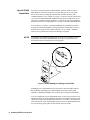
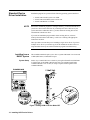
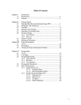
If you have an Agilent E1406 Command Module, and have 256Kb or more of
Flash ROM above the memory taken by your operating system, you can install
device drivers into it by setting the "RUN/LOAD" switch on the front of the
Command Module is set to "LOAD" (see Figure 1). Since this frees up memory that
you can use for additional NRAM or RDISK, and the drivers installed here are not
affected if you redefine memory parameters or cold boot the system, Flash ROM is
the preferred location for installing drivers if you have an E1406 Command Module.
You can check to see if there is enough Flash ROM left to download your drivers
by using the "DIAG:FROM:SIZE?" command while the "RUN/LOAD" switch on
the front of the Agilent E1406 Command Module is set to "LOAD." Additional
memory can be purchased from Agilent Technologies if required.
NOTE
You must have an installation program with a revision of 1.33 or higher to access
Flash ROM in the E1406 Command Module. If you have an older version you
should contact Agilent Technologies about an upgrade.
Figure 1. Switch Setting for Installing to Flash ROM
Installing drivers to Flash ROM does not affect drivers already installed in Driver
RAM (DRAM). Redefining Driver RAM (DRAM), User Non-volatile RAM
(NRAM), or RAM Disk (RDISK) does not affect drivers loaded into Flash ROM.
If you are installing drivers into Flash ROM, and if you also need to install a new or
updated operating system, the installation programs can install the operating system
and all device drivers to Flash ROM at the same time. To do this, you must have all
of the required files in the same hard disk directory. Please see the Installation Note
for your operating system update for more details on how to do this.
6 Installing SCPI Device Drivers
Driver RAM
Configuration
Before attempting to install any device drivers into Driver RAM you should
understand how memory is affected when you specify a size for one or more types
of RAM. There are three types of memory that you can allocate:
• RAM disk (RDISK)
• Non-volatile User RAM (NRAM)
• Driver RAM (DRAM)
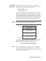
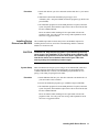
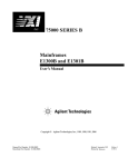
Figure 2 shows the positioning of the basic RAM memory areas. The first three
memory areas are temporary memory to which the user has no access. The last three
areas only exist if specified by the user. NRAM and RDISK both occupy higher
memory addresses than the DRAM. Because the size of these areas is variable, they
do not have a fixed starting position. At creation time, the lowest unused memory
address becomes the starting address for the requested type of RAM. Memory areas
set at higher addresses can be created without affecting previously created lower
memory areas, but creating a new memory area removes any areas above it.
NOTE
If you wish to use RDISK or NRAM, you can modify the configuration file so that
the installation program sets up the required memory segments.
FFFFFF16
System Non-volatile RAM
Instrument RAM
Operating System RAM
RAM Disk (RDISK)
Non-volatile User RAM (NRAM)
Driver RAM (DRAM)
Low Memory
The Low Address is equal to the highest address plus 1 (100000016) minus the size of memory
installed. The boot time messages will tell you how much RAM you have installed in your
system. In an Agilent E1406 with 512Kbytes of memory the Low Address is
low address = 100000016 - 8000016 = F8000016, or 16,252,928 decimal.
Figure 2. Positioning of Allocatable RAM
Example
If you create a RAM Disk area without creating any User Non-volatile RAM or
Driver RAM, the starting address for the RAM Disk will be at the lowest address
(F8000016 for a Command Module with 512Kbytes of memory). If you now create a
Driver RAM area, the RAM Disk area will be removed since the new area has to be
at a lower address then the RAM Disk area.
Installing SCPI Device Drivers 7
1
Setting System
Configuration
Default Configuration
If you do not use the default configurations for installing device drivers, you will
need to edit the appropriate configuration file to match your system configuration.
If the default values shown are correct for your setup, you can go to the appropriate
installation instructions.
The configuration defaults for transferring over an RS-232 link are::
•
•
•
•
•
•
The installation program searches for device drivers in the current directory.
Execution Log is OFF (log to screen only).
Device drivers in the current directory will be installed.
COM1 is used for output.
Baud rate is 9600.
1 stop bit is used
The configuration defaults for transferring over a GPIB (IEEE 488.2) link are:
•
•
•
•
Editing the
Configuration File
The installation program searches for device drivers in the current directory.
Execution Log is OFF (log to screen only).
Device drivers in the current directory will be installed.
The interface address is 70900.
The configuration file (VXIDLD.CFG if you are using the MS-DOS disks or
VXIDLD_CFG if you are using the LIF disks) on your device driver distribution
disk is shipped with all entries commented out, and the installation programs use
the default values listed. To activate or change an entry you must edit the file
manually using a standard text editor or word processor, or a BASIC language
editor. Comments and instructions are included in the file.
• The beginning of the useful information on each line is the part following
"line number REM" (the "line number REM" is ignored).
• Lines that start with "##" are comments.
• Lines that start with "#" are example configuration statements that you may
wish to activate and/or modify.
• Settings are not case sensitive, and should be separated from the associated
value by an equal sign ("=").
• Unrecognized settings are ignored.
• If you activate more than one line for a setting that can take only one value,
the first value found for the setting will be used.
8 Installing SCPI Device Drivers
Table 3. Configuration File Settings
Config. File Entry
DIRECTORY=
Allowed Values
Valid Directory
Default
Current Directory
Comments
Specifies the directory where you put the device
drivers and where the installation program logs
progress information. This directory must be
writeable if you are installing using MS-DOS or
IBASIC, or are logging progress.
EXECUTION LOG= Valid file name
Screen
Specifies where to log progress information. If you
specify a file name the installation program logs to
the screen and the file.
PROGRAM FILE= Valid program file Last set of program Specifies the program file (part 1) to install. Please
names
files found in
see the Installation Note for your operating system
current directory
update for more details on this entry.
DRIVER FILE=
Valid driver file
First 20 device
Specifies the driver file to install. The default when
names
driver files found in installing over GPIB is all drivers which end in
the current directory "DU". The default when installing over RS-232 is all
drivers ending with "DC". You can have multiple
driver file entries, each on a separate line.
ADDRESS=
Valid
For GPIB = 70900 Specifies the I/O interface to use. The default
communications
For RS-232 = 1
address over GPIB is 70900. The default address
port address.
when running over RS-232 is 1 (for COM1:).
BAUD=
300, 1200, 2400,
9600
Specifies the RS-232 interface baud rate for
4800, 7200, or 9600
transmission. The default is 9600.
STOP BITS=
1 or 2
1
Specifies the number of RS-232 stop bits per byte.
NRAM=
0 to available RAM
0 bytes
Specifies the size in bytes of the NRAM area to set
up. You can change this value without affecting
DRAM , but changing it will delete any RAM disk
that you have specified. The installation program
will stop if it finds NRAM already allocated.
RDISK=
0 to available RAM
0 bytes
Specifies the size in bytes of the RAM disk to set up.
You can change this value without affecting either
DRAM or NRAM. The installation program will
stop if it finds RAM Disk already allocated.
BEGINNING
Valid Command
none
Lets you send a command to the Command Module
COMMAND=
Module commands
before the installation program checks the
configuration. You can use multiple lines of this
entry if necessary.
SETUP
Valid Command
none
Lets you send a command to the Command Module
COMMAND=
Module commands
before the drivers have been downloaded and the
system rebooted with the requested memory. You
can use multiple lines of this entry.
CLEANUP
Valid Command
none
Lets you send a command to the Command Module
COMMAND=
Module commands
after the drivers are installed.
A GPIB address has the form "sspp00" where ss is the select code of the GPIB interface card, pp is the primary GPIB address used for the
Command Module, and 00 is the secondary GPIB address used for the Loader Instrument
The communication interface you will be using when running from DOS is the "RS-232" interface. When using an RS-232 interface, a serial
cable must be connected to the built-in RS-232 connection of the Command Module or an RS-232 module (Agilent E1324A) that is set to
interrupt at the default interrupt level (level 1). RS-232 addresses are 1 for COM1 or 2 for COM2:.
Installing SCPI Device Drivers 9
1
Standard Device
Driver Installation
NOTE
Installation programs are provided for the following operating systems/interfaces.
• Install from a BASIC system over GPIB.
• Install from an MS-DOS system over RS-232.
• Install from IBASIC over GPIB.
Because the installation programs re-configure memory, you must download all of
your device drivers at the same time. If you already have device drivers on your
system and wish to add another driver, you must delete the existing drivers and
reinstall them with the new driver.
If you start an installation program and it detects existing drivers, or detects
memory allocations that it will destroy, it will issue a warning with appropriate
instructions and abort.
These procedures assume that you are installing a single device driver. If you have
multiple device drivers you should copy all of the installation and driver files to a
single hard disk directory and run the installation program from that directory.
Installing from a
BASIC System
This installation method requires you to have a system with BASIC 5.0 or later and
a GPIB (IEEE 488.2) communications port.
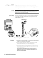
System Setup
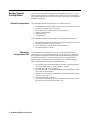
Set the "Sys Control/Talk Listen" switch on your Agilent E1300/E1301 Mainframe
to "Talk/Listen" or the GPIB Controller switch on your Agilent E1405/E1406
Command Module to zero or OFF (no setup is required for the Agilent E1306
Command Module).
E1300B/E1301B
Figure 3. Setting GPIB Controller Mode OFF
10 Installing SCPI Device Drivers
Procedure
1. Put the LIF disk into your drive and make sure that this drive is your current
drive.
2. Start BASIC and load the installation program (type ’GET
"VXIDLD_GET"’ and press ENTER) and run the program (type "RUN" and
press ENTER).
3. The installation program will create RAM partitions if required, reboot the
system if required, and install the required device driver files from the disk
into the Command Module.
Errors encountered while installing will be reported and will cause the
program to abort. You will get an error message with explanation, and in
most cases a suggested solution.
Installing Device
Drivers from MS-DOS
CAUTION
This installation procedure assumes that you have an MS-DOS computer for
installing the device drivers, and will be communicating with the Command
Module over an RS-232 link..
Terminate and Stay Resident programs in your MS-DOS system may
cause errors in the installation. If you encounter errors indicating that
the installation program did not receive back what it expected, and the
new device drivers are not loaded, remove all of your TSRs from
memory and try the installation procedure again.
System Setup
Make sure that the RS-232 port you are using is set for 9600 BAUD, 8 data bits, 1
stop bit, and parity check OFF before installing (these are the defaults for the
Command Module after cold boot). The installation program handles its own
pacing, so the setting for pacing does not matter.
Procedure
1. Put the MS-DOS disk into your disk drive and make sure that this drive is
your current drive and is writeable.
2. Execute the installation program (type "VXIDLD" and press ENTER).
3. The installation program will create RAM partitions if required, reboot the
system if required, and install the required device driver files from the disk
into the Command Module.
Errors encountered while installing will be reported and will cause the
program to abort. You will get an error message with explanation, and in
most cases a suggested solution.
Installing SCPI Device Drivers 11
Installing from IBASIC
This procedure assumes that you have the optional IBASIC installed in the
Command Module, and that the disk drive that will contain your AUTOST program
is at GPIB address 0 (zero). This procedure will not work correctly if your disk
drive is at any other GPIB address.
NOTE
If you wish to see the messages that the installation program generates, you need to
have a terminal connected to the IBASIC display port, and you must press the
IBASIC function key once IBASIC has loaded.
System Setup
Set the "Sys Control/Talk Listen" switch on your Agilent E1300/E1301 Mainframe
to "Sys Control" or the GPIB Controller switch on your Agilent E1405/E1406
Command Module to 1 or ON.
E1300B/E1301B
Figure 4. Setting GPIB Controller Mode ON
Procedure
1. Put the LIF disk or the MS-DOS disk into your disk drive and make sure that
this drive is your current drive and is writeable.
2. Turn the mainframe OFF and then ON again. Once IBASIC has loaded,
press the IBASIC function key so that you can watch progress.
3. The installation program will create RAM partitions if required, reboot the
system if required, and install the required device driver files from the disk
into the Command Module.
Errors encountered while installing will be reported and will cause the
program to abort. You will get an error message with explanation, and in
most cases a suggested solution.
12 Installing SCPI Device Drivers
1
Manual Device
Driver Installation
Installing Over GPIB
System Setup
Procedure
If you cannot use one of the supplied installation programs you will need to install
the device drivers manually. Manually downloading device drivers is fairly
straightforward because all drivers supplied by Agilent Technologies are formatted
so they can be transferred directly into Command Module memory.
The driver files (driver_DU) must be on media that is accessible to the computer
that will control the installation.
Set the "Sys Control/Talk Listen" switch on your Agilent E1300/E1301 Mainframe
to "Talk Listen" or the GPIB Controller switch on your Agilent E1405/E1406
Command Module to zero or OFF (see Figure 3). No specific setup is necessary for
the Agilent E1306 Command Module.
On most computers, a program will be required for the actual installation process.
Since driver files contain the command to start the installation plus the data to
transfer, this program just needs to set up the appropriate memory area and transfer
the driver files into it.
1. Send a *RST command and a *CLS command to the Command Module to
put it in a known state before beginning your installation.
2. Use the DIAG:DRAM commands to create the driver memory area if you
are installing into Driver RAM, or the DIAG:FROM commands if you are
installing into Flash ROM. If you are installing to Driver RAM and wish to
allocate NRAM or RDISK you should issue the appropriate commands at
this time.
3. If you are installing to Driver RAM, issue a DIAG:BOOT command to
reboot the Command Module and allocate the specified memory.
4. Transfer the device driver file to the Command Module. This file contains
the appropriate commands to accomplish the installation.
5. Send the SCPI query SYST:ERR? to make sure that there were no errors
during the installation.
6. Reboot your system if you installed to DRAM (send DIAG:BOOT), or send
the DIAG:DRIV:INST command and switch the "RUN/LOAD" switch to
the "RUN" position if you installed to Flash ROM.
7. Check to make sure that your drivers have been loaded into memory by
sending the SCPI command DIAG:DRIV:LIST:RAM? or
DIAG:DRIV:LIST:FROM? once you are in "RUN" mode.
Installing SCPI Device Drivers 13
Installing Over RS-232
Transmission Format
Although similar in concept to manual installation over GPIB, manual installation
over RS-232 is complicated by the lack of built in pacing. The driver files
(driver.DC) must be on media that is accessible to the computer that will control the
installation.
You need to make sure that the transmission format of your computer matches the
format used in the Command Module. The default configuration for the Command
Module after a DIAG:BOOT:COLD command has been issued is
•
•
•
•
•
9600 BAUD
8 data bits
1 stop bit
Parity checking is OFF
XON/XOFF pacing
If you are going to use any other setting, you must set up the appropriate settings in
the Command Module using the following commands:
COMM:SER[n]:REC:BAUD <rate>
COMM:SER[n]:REC:SBITS <bits>
DIAG:COMM:SER[n]:STOR
NOTE
Pacing the Data
sets BAUD rate
sets number of stop bits
saves settings so they will be
kept through a reboot.
Because the formatting for binary files uses 8 data bits, you must set the number of
data bits to 8 and parity checking OFF for the device driver files to transfer properly.
Since the RS-232 interface is asynchronous, the computer that is doing the transfer
can overrun the Command Module, causing part of the device driver to be lost. To
prevent this from happening, you must enable a handshake protocol.
The default for the Command Module is software handshake enabled and hardware
handshake disabled. To set up software handshake, use:
SYST:COMM:SER:PACE:THR:STOP? MAX
to find the maximum number of characters to fill the input
buffer.
SYST:COMM:SER:PACE:THR:STOP <max-20>
to set the threshold for stopping data to the maximum size of
the input buffer minus 20 characters.
SYST:COMM:SER:PACE:THR:STAR 0
to set the start buffer level to zero. This makes sure that the
input buffer is flushed whenever transmissions are stopped.
SYST:COMM:SER:PACE:XON
to enable the software handshake protocol.
The start threshold must be less than the stop threshold. The stop threshold must be
set low enough to handle the maximum number of characters that are likely to be
received at the Command Module after it sends the XOFF signal.
Hardware handshake can be set to use DTR (Data Terminal Ready) or RTS (Ready
to Send). Use SYST:COMM:SER:CONT:DTR IBFULL to set DTR mode or
14 Installing SCPI Device Drivers
SYST:COMM:SER:CONT:RTS IBFULL to set RTS mode. Use
SYST:COMM:SER:PACE NONE to set software handshake OFF. When the
Command Module input buffer is not full, the specified hardware line is asserted.
When either hardware handshake mode is enabled the Command Module will not
transmit characters when either the CTS (Clear to Send) or the DSR (Data Set
Ready) lines are not asserted.
NOTE
CAUTION
The Command Module RS-232 interface is implemented as DTE (Data Terminating
Equipment). Since most computer RS-232 interfaces are also implemented as DTE,
you will need a null modem cable (which swaps the receive and transmit lines) to
connect the computer to the Command Module.
The Command Module RS-232 interface echoes any characters received with an
ASCII value greater than 32 and less than 128. Carriage returns are echoed as
carriage return/linefeed. These echoes can fill up the RS-232 receive buffer of your
computer if they are not read, and cause the computer to send the "Stop
Transmitting" signal to the Command Module, which could block the remaining
transmitted bytes or other commands sent after the installation.
Since the device driver files contain command strings and many carriage returns
that will be echoed, your program should read the returning echo characters. This
will also let you see if there are any error messages being returned.
Procedure
On most computers, a program will be required for the actual installation process.
Since the driver files contain the command to start the installation plus the actual
data to transfer, this program just needs to set up the appropriate memory area and
transfer the driver files into it.
1. Send a *RST command and a *CLS command to the Command Module to
put it in a known state before beginning your installation.
2. Use the DIAG:DRAM commands to create the memory area if you are
installing into Driver RAM, or the DIAG:FROM commands if you are
installing into Flash ROM. If you are installing to Driver RAM and wish to
allocate NRAM or RDISK you should issue the appropriate commands at
this time.
3. If you are installing to Driver RAM, issue a DIAG:BOOT command to
reboot the Command Module and allocate the specified memory.
4. Transfer the device driver file to the Command Module. This file contains
the appropriate commands to accomplish the installation.
5. Send the SCPI query SYST:ERR? to make sure that there were no errors
during the installation.
6. Reboot your system if you installed to DRAM (send DIAG:BOOT), or send
the DIAG:DRIV:INST command and switch the "RUN/LOAD" switch to
the "RUN" position if you installed to Flash ROM.
Installing SCPI Device Drivers 15
7. Check to make sure that your drivers have been loaded into memory by
sending the SCPI command DIAG:DRIV:LIST:RAM? or
DIAG:DRIV:LIST:FROM? once you are in "RUN" mode.
Transferring Device Drivers Using a COPY Command
On some computers it is possible to use an RS-232 port and the copy command to
transfer the device driver files. Hardware or software handshake must be used by
the copy command on the computer doing the installing, and the same handshake
mode must be enabled on the Command Module.
1. Set the required handshake mode and data format (e.g., on DOS systems use
the MODE command).
2. Type "COPY filename port" to transfer the file through the RS-232 port to
the Loader Instrument (e.g., on a DOS system you might use "COPY B:\
filename.DC COM1:"). This command may be slightly different depending
on the type of computer being used.
NOTE
Since errors are echoed immediately, this method of transfer has no means of
trapping errors.
Transferring Device Drivers Using a CAT Command
On HP-UX systems you can use the cat command to transfer the device driver files.
The appropriate Unix® device file must exist. All shell commands are assumed to
be executed from either the /bin/sh or /bin/ksh shell.
1. Start a process that opens the Unix device file to be used. This process
should keep the device file open long enough for the transfer to begin. This
step is done so that the following command to set the device file
configurations will remain in effect for the transfer. A command that will do
this is:
(cat < device file > /dev/null; sleep 1000) &
NOTE
To check for errors you can substitute a real file name for "/dev/null" in the above
statement. This file will contain the output of the System/Loader Instrument which
would include any errors reported.
2. Set the required configuration of the Unix device file using the stty
command The following command will set the device file to work with the
default Command Module configuration.
stty -opost 9600 ixon -ixoff cs8 -cstopb ignpar < device file
3. Transfer the file to the Command Module with the cat command.
cat filename > device file
16 Installing SCPI Device Drivers
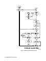
Transferring Device Drivers Using Custom Software
If the COPY command on your computer cannot directly implement handshaking,
or if you wish to trap errors and abort or otherwise modify the transmission process,
you must use a program to handle the installation.
This procedure assumes that your computer has some means of looking at data
being echoed from the Command Module, and can check for a return character
without having to have a character returned. Since the actual operating system
program file bytes sent over the RS-232 interface are not echoed, the lack of ability
to do this would put the system into an infinite wait at the first byte that was not
echoed.
1. Set up the appropriate handshake mode and data format on your system, and
the matching handshake mode in the System Instrument.
2. Transfer the device driver files over the RS-232 interface using a program
that follows the outline in Figure 5.
Installing SCPI Device Drivers 17
Figure 5. Manually Installing a Device Driver
18 Installing SCPI Device Drivers


![[S30830T-CPE] Users Manual: CPE83SUE](http://vs1.manualzilla.com/store/data/005890174_1-2a1526c3cbd1c0db150881a0418c3ddc-150x150.png)