1
ACCES I/O PRODUCTS INC
10623 Roselle St., San Diego, CA 92121
Tel:(619)550-9559 FAX (619)550-7322
ANALOG, DIGITAL I/O CARD
AD8-16
USER MANUAL
File: mad8-16.b5a
NOTICES
The information in this document is provided for reference only. ACCES does not assume
any liability arising out of the application or use of the information or products described
herein. This document may contain or reference information and products protected by
copyrights or patents and does not convey any license under the patent rights of ACCES,
nor the rights of others.
IBM PC, PC/XT, and PC/AT are registered trademarks of the International Business
Machines Corporation.
Printed in USA. Copyright 1993 by ACCES, 10623, Roselle Street, San Diego,CA 92121.
All rights reserved.
ANALOG/DIGITAL I/O CARD
AD8-16
USER MANUAL
TABLE OF CONTENTS
INSTALLATION . . . . . . . . . . . . . . . . . . . . . . . . . . . . . . . . . . . . . . . . . . . .
CD INSTALLATION . . . . . . . . . . . . . . . . . . . . . . . . . . . . . . . . . . . . . .
3.5-INCH DISKETTE INSTALLATION . . . . . . . . . . . . . . . . . . . . . . .
DIRECTORIES CREATED ON THE HARD DISK . . . . . . . . . . . . . . .
INSTALLING THE CARD . . . . . . . . . . . . . . . . . . . . . . . . . . . . . . . . .
1-1
1-1
1-1
1-2
1-5
FUNCTIONAL DESCRIPTION . . . . . . . . . . . . . . . . . . . . . . . . . . . . . . . . .
ANALOG INPUTS . . . . . . . . . . . . . . . . . . . . . . . . . . . . . . . . . . . . . . . .
ANALOG OUTPUTS . . . . . . . . . . . . . . . . . . . . . . . . . . . . . . . . . . . . . .
DIGITAL INPUTS . . . . . . . . . . . . . . . . . . . . . . . . . . . . . . . . . . . . . . . .
DIGITAL OUTPUTS . . . . . . . . . . . . . . . . . . . . . . . . . . . . . . . . . . . . . .
BLOCK DIAGRAM . . . . . . . . . . . . . . . . . . . . . . . . . . . . . . . . . . . . . . .
2-1
2-1
2-2
2-2
2-2
2-4
HARDWARE CONFIGURATION AND INSTALLATION . . . . . . . . . . . .
OPTIONS SELECTED BY JUMPER . . . . . . . . . . . . . . . . . . . . . . . . . .
FACTORY INSTALLED OPTION . . . . . . . . . . . . . . . . . . . . . . . . . . .
OPTION SELECTION MAP . . . . . . . . . . . . . . . . . . . . . . . . . . . . . . . .
3-1
3-1
3-2
3-3
ADDRESS SELECTION . . . . . . . . . . . . . . . . . . . . . . . . . . . . . . . . . . . . . . . 4-1
ADDRESS ASSIGNMENTS FOR 286/386/486 . . . . . . . . . . . . . . . . . . 4-1
SOFTWARE . . . . . . . . . . . . . . . . . . . . . . . . . . . . . . . . . . . . . . . . . . . . . . . . 5-1
BASE ADDRESS LOCATOR PROGRAM . . . . . . . . . . . . . . . . . . . . . . 5-1
SETUP PROGRAM . . . . . . . . . . . . . . . . . . . . . . . . . . . . . . . . . . . . . . . 5-1
DRIVER . . . . . . . . . . . . . . . . . . . . . . . . . . . . . . . . . . . . . . . . . . . . . . . . 5-1
DRIVER TASK DESCRIPTIONS . . . . . . . . . . . . . . . . . . . . . . . . . . . . 5-2
USING THE DRIVER WITH BASIC . . . . . . . . . . . . . . . . . . . . . . . . . . 5-7
CALLS IN OTHER LANGUAGES . . . . . . . . . . . . . . . . . . . . . . . . . . . 5-7
AD8-16 WINDOWS DRIVER REFERENCE . . . . . . . . . . . . . . . . . . . . 5-8
USING THE DRIVER . . . . . . . . . . . . . . . . . . . . . . . . . . . . . . . . . . . . . 5-8
TASK SUMMARY . . . . . . . . . . . . . . . . . . . . . . . . . . . . . . . . . . . . . . 5-11
TASK REFERENCE . . . . . . . . . . . . . . . . . . . . . . . . . . . . . . . . . . . . . 5-12
AD816_Init . . . . . . . . . . . . . . . . . . . . . . . . . . . . . . . . . . 5-12
AD816_Shutdown . . . . . . . . . . . . . . . . . . . . . . . . . . . . . 5-12
AD816_SetPointConfig . . . . . . . . . . . . . . . . . . . . . . . . . 5-13
AD816_FetchPointConfig . . . . . . . . . . . . . . . . . . . . . . . 5-13
AD816_AddPoints . . . . . . . . . . . . . . . . . . . . . . . . . . . . 5-14
AD816_ResetListIndex . . . . . . . . . . . . . . . . . . . . . . . . . 5-14
AD816_ClearPointList . . . . . . . . . . . . . . . . . . . . . . . . . . 5-14
AD816_DelPtListIndexes . . . . . . . . . . . . . . . . . . . . . . . . 5-15
AD816_SetSettleTime . . . . . . . . . . . . . . . . . . . . . . . . . . 5-15
AD816_GetNextPoint . . . . . . . . . . . . . . . . . . . . . . . . . . 5-16
AD816_GetIndexPoint . . . . . . . . . . . . . . . . . . . . . . . . . . 5-16
AD816_GetDirectPoint . . . . . . . . . . . . . . . . . . . . . . . . . 5-17
AD816_IRQTerminate . . . . . . . . . . . . . . . . . . . . . . . . . 5-17
AD816_IRQStatus . . . . . . . . . . . . . . . . . . . . . . . . . . . . 5-18
AD816_IRQScan . . . . . . . . . . . . . . . . . . . . . . . . . . . . . . 5-18
i
ANALOG/DIGITAL I/O CARD
AD8-16
USER MANUAL
AD816_PollScan . . . . . . . . . . . . . . . . . . . . . . . . . . . . . .
AD816_PostProcess . . . . . . . . . . . . . . . . . . . . . . . . . . .
AD816_DACOut . . . . . . . . . . . . . . . . . . . . . . . . . . . . .
AD816_DigitalOut . . . . . . . . . . . . . . . . . . . . . . . . . . . . .
AD816_DigitalIn . . . . . . . . . . . . . . . . . . . . . . . . . . . . . .
AD816_SetCounter . . . . . . . . . . . . . . . . . . . . . . . . . . . .
AD816_ReadCounter . . . . . . . . . . . . . . . . . . . . . . . . . . .
AD816_RateGenerator . . . . . . . . . . . . . . . . . . . . . . . . . .
AD816_DisableCounter . . . . . . . . . . . . . . . . . . . . . . . . .
AD816_MeasureFreq . . . . . . . . . . . . . . . . . . . . . . . . . . .
AD816_MeasurePeriod . . . . . . . . . . . . . . . . . . . . . . . . .
SUMMARY OF ERROR CODES . . . . . . . . . . . . . . . . . . . . . . . . . . . .
5-20
5-21
5-21
5-22
5-22
5-23
5-23
5-24
5-24
5-25
5-25
5-27
PROGRAMMING . . . . . . . . . . . . . . . . . . . . . . . . . . . . . . . . . . . . . . . . . . . . 6-1
CONNECTOR PIN ASSIGNMENTS . . . . . . . . . . . . . . . . . . . . . . . . . . . . . 7-1
SPECIFICATIONS . . . . . . . . . . . . . . . . . . . . . . . . . . . . . . . . . . . . . . . . . . . 8-1
WARRANTY . . . . . . . . . . . . . . . . . . . . . . . . . . . . . . . . . . . . . . . . . . . . . . . 9-1
APPENDIX A
PROGRAMMABLE COUNTER/TIMER
APPLICATIONS . . . . . . . . . . . . . . . . . . . . . . . . . . . . . . . . . . . . . . . . . A-1
OPERATION MODES . . . . . . . . . . . . . . . . . . . . . . . . . . . . . . . . . . . . . A-1
PROGRAMMING . . . . . . . . . . . . . . . . . . . . . . . . . . . . . . . . . . . . . . . . A-2
APPENDIX B
SAMPLE PROGRAMS . . . . . . . . . . . . . . . . . . . . . . . . . . . . . . . . . . . . B-1
ii
ANALOG/DIGITAL I/O CARD
AD8-16
USER MANUAL
INSTALLATION
The software provided with this card is contained on either one CD or multiple diskettes
and must be installed onto your hard disk prior to use. To do this, perform the following
steps as appropriate for your software format and operating system. Substitute the
appropriate drive letter for your CD-ROM or disk drive where you see d: or a:
respectively in the examples below.
CD INSTALLATION
DOS/WIN3.x
1.
2.
3.
4.
WIN95/98/NT
1.
2.
3.
4.
Place the CD into your CD-ROM drive.
Type d:K to change the active drive to the CD-ROM
drive.
Type installK to run the install program.
Follow the on-screen prompts to install the software for
this card.
Place the CD into your CD-ROM drive.
The CD should automatically run the install program after 30
seconds. If the install program does not run, click START | RUN and
type d:install, click OK or press K.
Follow the on-screen prompts to install the software for this card.
Click the “Go to ACCES Web” button to check for software updates.
3.5-INCH DISKETTE INSTALLATION
As with any software package, you should make backup copies for everyday use and store
your original master diskettes in a safe location. The easiest way to make a backup copy
is to use the DOS DISKCOPY utility.
In a single-drive system, the command is:
diskcopy a: a:K
You will need to swap disks as requested by the system.
In a two-disk system, the command is:
diskcopy a: b:K
1-1
ANALOG/DIGITAL I/O CARD
AD8-16
USER MANUAL
This will copy the contents of the master disk in drive A to the backup disk in drive B.
To copy the files on the master diskette to your hard disk, perform the following steps.
1.
Place the master diskette into a floppy drive
2.
Change the active drive to the drive that has the diskette installed. For
example, if the diskette is in drive A, type a:K.
3.
Type installK and follow the on-screen prompts.
DIRECTORIES CREATED ON THE HARD DISK
The installation process will create several directories on your hard disk. If you accept the
installation defaults, the following structure will exist.
[CARDNAME]
Root or base directory containing the SETUP.EXE setup program
used to help you configure jumpers and calibrate the card. The
directory also contains PCIFind.EXE, a utility to locate resources
used by installed PCI-bus data acquisition cards.
DOS\PSAMPLES:
A subdirectory of [CARDNAME] that contains Pascal samples.
DOS\CSAMPLES:
A subdirectory of [CARDNAME] that contains “C” samples.
WIN32\SAMPLE.lang Subdirectories containing samples for Win95/98 and NT.
ACCES32:
This directory contains the Windows 95/98/NT driver used to provide
access to the hardware registers when writing 32-bit Windows
software. Several samples are provided in a variety of languages to
demonstrate how to use this driver. The DLL provides four functions
(InPortB, OutPortB, InPort, and OutPort) to access the hardware.
This directory also contains the device driver for NT. This device
driver provides register-level hardware access from Windows NT,
normally called through ACCES32.DLL. Two methods of using the
driver are provided, the ACCES32.DLL (recommended) and the
deviceiocontrol handles direct to the sys file (slightly faster)
DLL: Samples for using ACCES32.DLL are provided in this
directory. Using this DLL not only makes the hardware
programming easier (MUCH easier), but also one source file
can be used for both Windows 95/98 and WindowsNT. One
executable can run under both operating systems and still
have full access to the hardware registers. The DLL is used
exactly like any other DLL, so it is compatible with any
language capable of using 32-bit DLLs. Consult the manuals
1-2
ANALOG/DIGITAL I/O CARD
AD8-16
USER MANUAL
provided with your language’s compiler for information on
using DLLs in your specific environment.
SYS: The samples in this directory are provided ONLY for Windows
NT. The DeviceIOControl based interaction with the registerlevel driver is only available in NT. If your code is written to
use this method, it will not work with Windows 95 or Windows
98.
The SYS file is the actual workhorse behind hardware access
in Windows NT. It utilizes the DeviceIOControl API function
for interaction with user code. Samples are provided
demonstrating this API call, but it is strongly recommended
that the DLL interface be used. The DLL, described previously
encapsulates the SYS file and performs the DeviceIOControl
calls at a small penalty in speed. (A call through the DLL
interface)
VBACCES:
PCI:
This directory contains sixteen-bit DLL drivers for use with
VisualBASIC 3.0 and Windows 3.1 only. These drivers provide four
functions, similar to the ACCES32.DLL. However, this DLL is only
compatible with 16-bit executables. Migration from 16-bit to 32-bit is
simplified because of the similarity between VBACCES and
ACCES32.
This directory contains PCI-bus specific programs and information.
If you are not using an ACCES PCI card, you can ignore or delete this
directory.
SOURCE:
WIN32IRQ:
A utility program is provided with source code you can
use to determine allocated resources at run-time from
your own programs in DOS.
This directory provides a generic interface for IRQ handling in
Windows 95/98/NT. Source code is provided for the driver, greatly
simplifying the creation of custom drivers for specific needs. Samples
are provided to demonstrate the use of the generic driver. Note that
the use of IRQs in near-real-time data acquisition programs requires
multi-threaded application programming techniques and must be
considered an intermediate to advanced programming topic. Delphi,
C++ Builder, and Visual C++ samples are provided.
PCIFind.exe A utility for DOS and Windows to determine PCI bus resources allocated to
installed PCI cards. Use this utility to find what base address and IRQ your
1-3
ANALOG/DIGITAL I/O CARD
AD8-16
USER MANUAL
cards are installed at on the PCI bus. This program runs two versions,
depending on the operating system. Windows 95/98/NT displays a GUI
interface, and modifies the registry. When run from DOS or Windows3.x, a
text interface is used. For information about the format of the registry key,
consult the card-specific samples provided with the hardware. In Windows
NT, NTioPCI.SYS runs each time the computer is booted, thereby refreshing
the registry as PCI hardware is added or removed. In Windows 95/98/NT
PCIFind.EXE places itself in the boot-sequence of the OS to refresh the
registry on each power-up.
This program also provides some COM configuration when used with PCI
COM ports. Specifically, it will configure compatible COM cards for IRQ
sharing and multiple port issues.
Findbase.exe
DOS utility to determine an available base address for ISA bus , nonPlug-n-Play cards. Run this program once, before the hardware is
installed in the computer, to determine an available address to give
the card. Once the address has been determined, run the setup
program provided with the hardware to see instructions on setting the
address switch and various option selections.
Poly.exe
A generic utility to convert a table of data into an nth order polynomial.
Useful for calculating linearization polynomial coefficients for
thermocouples and other non-linear sensors.
Risc.bat
A batch file demonstrating the command line parameters of
RISCTerm.exe.
RISCTerm.exe
A dumb-terminal type communication program designed for
RS422/485 operation. Used primarily with REMOTE ACCES Data
Acquisition Pods and our RS422/485 serial communication product
line. Can be used to say hello to an installed modem. RISCTerm
stands for Really Incredibly Simple Communications TERMinal.
1-4
ANALOG/DIGITAL I/O CARD
AD8-16
USER MANUAL
INSTALLING THE CARD
Before installing the card, carefully read the ADDRESS SELECTION and OPTION
SELECTION sections of this manual and configure the card according to your
requirements.
Be especially careful with address selection. If the address of two installed functions
overlaps you will experience unpredictable computer behavior. AD8-16 occupies 16
consecutive bytes of address space. If unsure what locations are available, you can use
the FINDBASE program to locate blocks of available addresses.
To install the card:
1. Turn off computer power.
2. Remove the computer cover.
3. Remove the blank I/O backplate.
4. Install jumpers for selected options. See section 3 of this manual.
5. Select the base address on the card. See section 4 of this manual
6. Install the card in an I/O expansion slot. Make sure that the card mounting bracket
is properly screwed into place and that there is a positive chasis ground.
7. Install the I/O cable.
8. Inspect for proper fit of the card and cable. Tighten screw.
9. If everything checks good, replace the cover and apply power.
To ensure that there is minimum susceptibility to EMI and minimum radiation, it is
important that there be a positive chassis ground. Also, proper EMI cabling techniques
must be used for input/output wiring.
1-5
ANALOG/DIGITAL I/O CARD
AD8-16
USER MANUAL
This page purposely omitted
1-6
ANALOG/DIGITAL I/O CARD
AD8-16
USER MANUAL
FUNCTIONAL DESCRIPTION
FEATURES
i
i
i
i
i
16 Single-Ended or 8 Differential Analog Inputs
Two 8-Bit Analog Outputs
Three Programmable Counter/Timers
Eight Digital Inputs
Eight Digital Outputs
APPLICATIONS
Schools, Labs, and Process Monitoring/Control where low cost is more important than
resolution. The AD8-16 card provides accuracy +/- 0.1% +/- 1 Count.
DESCRIPTION
The AD8-16 card should be installed in a full size slot of an IBM PC/XT/AT or compatible
computer. Power requirements are only 0.5A of +5VDC, and 20mA each of +12VDC, and
-12VDC. The card provides +5VDC power supply output (via a 1A fuse located on the
card) for external use.
The AD8-16 card is designed for easy maintenance. Calibration is not required and there
are no user adjustments. Generous silk screened legends and multiple test points allow
fast identification of individual circuits. Finally, there is overvoltage protection on the I/O
lines.
The card occupies sixteen consecutive bytes of I/O address space, and can be located
anywhere in the I/O range of 000-3FF hex by DIP switch selection. See section 4,
ADDRESS SELECTION, for a detailed description.
ANALOG INPUTS: Sixteen single-ended or eight differential analog inputs are
multiplexed, amplified, held by a sample and hold circuit, and converted to digital data by
an eight-bit analog-to- digital converter (A/D).
The multiplexer can be used in two modes: 16 single-ended or eight differential channels.
The selection is done by jumper installation. Channel selection is controlled by software.
The analog signal selected by the multiplexer is amplified. Amplifier gain is selected by
software and can differ from channel to channel. Gain selection produces unipolar ranges
of 0 to 256mV and 0 to 10V and bipolar input ranges +/-128mV and +/-5V. See section 5
of this manual, PROGRAMMING, for a detailed description.
The sample and hold circuit prevents fast-changing analog signals from introducing errors
2-1
ANALOG/DIGITAL I/O CARD
AD8-16
USER MANUAL
during the digitizing process of the A/D Converter. The sample and hold circuit used
requires a settling time of 50uSec for accuracy of 0.1% when a full-scale step signal is
applied.
A type AD-670 A/D converter is used on the AD8-16 card. It features 10uSec conversion
time, differential input, and built-in common mode rejection. An End-of-Conversion signal
can be used to interrupt the computer. You can select Interrupt levels #2 through #7.
Available conversion formats:
Bipolar: The digital output for bipolar operation is available in two formats:
Offset Binary:
2's Complement:
0 = 1000 0000 -1 = 0111 1111
0 = 0000 0000 -1 = 1111 1111
Unipolar: The digital output for unipolar operation is available in two formats:
Straight Binary:
0 = 0000 0000 +1 = 0000 0001
2's Complement:
0 = 0000 0000 +1 = 0000 0001
(2's complement normally not used for unipolar)
ANALOG OUTPUTS: The card contains two 8-bit digital-to-analog converters (DAC).
Voltage outputs are from -10 VDC to +10 VDC based on the following digital inputs:
1111 1111
1000 0000
0000 0000
+ 9.92 VDC
0.00 VDC
- 10.00 VDC
Since the DAC is an eight-bit device, the analog output varies in 256 discrete steps as the
input digital number is changed from plus full scale to minus full scale.
The DAC outputs can drive 10 Kilohm (or greater) resistive loads with full accuracy.
DIGITAL INPUTS: The card can accept eight discrete inputs. For an input signal to be
recognized as a low it should not exceed 0.8 VDC. A high input may be a voltage from 2.5
to 24 VDC, or an open switch. All digital inputs are pulled up to 5VDC by 1 Kilohm resistors
installed on the card.
DIGITAL OUTPUTS: The card provides eight discrete outputs. These outputs may be
used to communicate to other digital equipment or to drive relays, indicators, etc. The
outputs have pull-down capability of 24 mA, with a Zener diode clamp at +5.6 VDC. At
system turn-on and/or Reset, digital outputs are tri-stated and remain so until the computer
writes to the digital output port.
2-2
ANALOG/DIGITAL I/O CARD
AD8-16
USER MANUAL
PROGRAMMABLE TIMER-COUNTERS: The AD8-16 card contains a Timer/Counter type
8254, which has three 16-bit, fully programmable synchronous counters. These counters
are loaded and read by software.
You can configure the individual gates, clocks, and outputs of all three counters either at
the I/O connector or by installing jumpers on the AD8-16 card. There are three possible
clock sources to choose from for counter operation; (a.) the computer clock, (b.) the Color
Oscillator, and (c.) an external clock source applied via the I/O connector. If you select
either of the internal sources, then you can also select 1/2, 1/4, 1/8, or 1/16 the frequency
of that source by means of jumpers.
2-3
ANALOG/DIGITAL I/O CARD
AD8-16
USER MANUAL
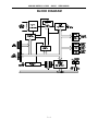
BLOCK DIAGRAM
2-4
ANALOG/DIGITAL I/O CARD
AD8-16
USER MANUAL
HARDWARE CONFIGURATION AND INSTALLATION
When reading this section of the manual, refer to the BLOCK DIAGRAM on the preceding
page, the OPTION SELECTION MAP on a following page, and the SETUP executive
program provided with the card. Options are selected on the AD8-16 card by installing
jumpers at locations labeled by silk screen. A description of available options follows. The
silk-screen label, where applicable, is listed in capital letters.
OPTIONS SELECTED BY JUMPER
ADDRESS SELECT(A4-A9): See the next section of this manual, ADDRESS SELECTION,
for a detailed description of how to select the card base address.
INTERRUPT SELECT (IRQ2 - IRQ7): Select the desired Interrupt level by installing a
jumper at the location marked IRQ2 through IRQ7. An Interrupt is generated on the
AD8-16 card when an analog-to-digital conversion is completed. The Interrupt is canceled
automatically when A/D conversion data are read at (Base Address + 0), or when the
computer writes to (Base Address + 1). See PROGRAMMING, section 5.
CLK-OSC: Select the Counter/Timer clock source by installing this jumper. When a jumper
is installed in the location marked CLK, the computer clock is selected. When a jumper is
installed in location marked OSC, the oscillator clock (always 14.31818 MHz) is selected.
It is suggested to use the oscillator clock because the frequency will be the same if the
card is transported to another computer.
CLK/2: Installing this jumper supplies the selected internal source clock frequency divided
by two to the 8254 Counter/Timer. The clock supplied to the Counter/Timer must be slower
then 4 MHz. This jumper should not be installed when the oscillator clock source
(14.31818 Mhz) is selected. Further, only one jumper should be installed in a CLK/2,
CLK/4, CLK/8, CLK/16 location.
CLK/4, CLK/8, CLK/16: As above except that the clock frequency is divided by four, eight,
and sixteen respectively.
CTR0 CLK: Installing this jumper selects the Counter/Timer 0 clock frequency. That
frequency is determined by CLK-OSC, and CLK/2, CLK/4, CLK/8, and CLK/16 selection.
The Counter/Timer clock can also be externally supplied through the I/O connector. Note,
however, that the highest frequency that can be applied to the counter is 4 MHz.
CTR0 OUT: Installing this jumper supplies the output of the Counter/Timer 0 as a clock
input to Counter/Timer 1. This option allows you to cascade counters. Do not install when
jumper CTR1 CLK is installed.
3-1
ANALOG/DIGITAL I/O CARD
AD8-16
USER MANUAL
CTR1 CLK: Installing this jumper selects Counter/Timer 1 clock frequency. That frequency
is determined by CLK-OSC, and CLK/2, CLK/4, CLK/8, and CLK/16 selection. Do not
install when jumper CTR0 OUT is installed. The Counter/Timer clock can also be externally supplied through the I/O connector. Note, however, that the highest frequency that
can be applied to the counter is 4 MHz.
CTR1 OUT: Installing this jumper supplies the output of the Counter/Timer 1 as a clock
input to Counter/Timer 2. This option allows you to cascade counters. Do not install when
jumper CTR2 CLK is installed.
CTR2 CLK: Installing this jumper selects Counter/Timer 2 clock frequency. That frequency
is determined by CLK-OSC, and CLK/2, CLK/4, CLK/8, and CLK/16 selection. Do not
install when jumper CTR1 OUT is installed. The Counter/Timer clock can also be externally supplied through the I/O connector. Note, however, that the highest frequency that
can be applied to the counter is 4 MHz.
CTR2 OUT: Installing this jumper supplies the output of the Counter/Timer 2 as a clock to
begin an analog-to-digital conversion.
DIF-SE: Select differential (eight analog input channels), or single- ended (sixteen analog
input channels) mode of operation by installing this jumper.
FACTORY INSTALLED OPTION
Option CMR Improved Common Mode Rejection: Components installed at R23-R25 and
at U8 provide improved common mode voltage performance.
3-2
ANALOG/DIGITAL I/O CARD
AD8-16
USER MANUAL
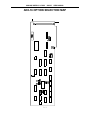
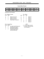
AD8-16 OPTION SELECTION MAP
3-3
ANALOG/DIGITAL I/O CARD
AD8-16
USER MANUAL
This page purposely omitted
3-4
ANALOG/DIGITAL I/O CARD
AD8-16
USER MANUAL
ADDRESS SELECTION
The Analog/ Digital I/O Card, AD8-16, occupies sixteen consecutive bytes within I/O
address space. The illustrated SETUP program provided with the card includes a routine
for setting Base Address. The Base Address can be selected anywhere within the I/O
address range 100-3FF hex. If the addresses of two installed functions overlap, you will
experience unpredictable computer behavior. The FINDBASE program supplied on by CD
by ACCES will assist you in selecting a base address that will avoid this conflict.
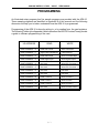
STANDARD ADDRESS ASSIGNMENTS FOR 286/386/486 COMPUTERS
Hex Range
000-01F
020-03F
040-05F
060-06F
070-07F
080-09F
0A0-0BF
0C0-0DF
0F0
0F1
0F8-0FF
1F0-1F8
200-207
278-27F
2F8-2FF
300-31F
360-36F
378-37F
380-38F
3A0-3AF
3B0-3BF
3C0-3CE
3D0-3DF
3F0-3F7
3F8-3FF
Usage
DMA Controller 1
INT Controller 1, Master
Timer
Keyboard
Real-Time clock, NMI Mask Register
DMA Page Register
INT Controller 2
DMA Controller 2
Clear Math Coprocessor Busy
Reset Coprocessor
Arithmetic Processor
Fixed Disk
Game I/O
Parallel Printer Port 2
Asynchronous Comm'n (Secondary)
Prototype Card
Reserved
Parallel Printer Port 1
SDLC or Binary Synchronous Comm'n 2
Binary Synchronous Comm'n 1
IBM Monochrome Display/Printer
Local Area Network
Color/Graphics
Diskette
Asynchronous Comm'n (Primary)
The following is presented to help you understand the process of setting Base Address.
Address setup switches are marked A4, A5, A6, A7, A8, and A9. In order to configure the
desired address, assign '1' to all address setup switches turned ON, and assign '0' to all
address setup switches turned OFF. These 1's and 0's form a binary representation of the
base address. The binary representation is then converted to hexadecimal for
programming.
4-1
ANALOG/DIGITAL I/O CARD
AD8-16
USER MANUAL
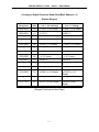
The following example illustrates the above process: In this case, switch selection
corresponds to binary 10 1010 xxxx (or hex 2A). The "xxxx" represent address lines A3,
A2, A1, and A0 used on the card to select individual registers. (See the PROGRAMMING
section of this manual).
Address Line Controlled
A9
A8
A7
A6
A5
A4
Switch Identification
A9
A8
A7
A6
A5
A4
Switch Setup
ON
OFF
ON
OFF
ON
OFF
Binary Representation
1
0
1
0
1
0
Hex Conversion Factors
2
1
8
4
2
1
Hex Representation
2
A
Note: To obtain a hex representation, add hex conversion factors corresponding to "1" in
the binary representation row. Remember that:
A(hex)=10(decimal), B(hex)=11(decimal), C(hex)=12(decimal)
D(hex)=13(decimal), E(hex)=14(decimal), F(hex)=15(decimal)
4-2
ANALOG/DIGITAL I/O CARD
AD8-16
USER MANUAL
SOFTWARE
INTRODUCTION
The CD supplied by ACCES with the AD8-16 contains several programs. There are a base
address locator program called FINDBASE, a Setup program, three Driver programs for
MS_DOS and five Sample programs. The Drivers and the Sample programs are provided
in three forms; a C language linkable file, a QuickBASIC and Pascal linkable form. The
Sample programs are:
Sample 1: A/D Conversion on eight differential inputs
using polling
Sample 2: A/D Conversion on sixteen single-ended inputs using interrupts
Sample 3: D/A Conversions
Sample 4: Counter control
Sample 5: Reading digital inputs
BASE ADDRESS LOCATOR PROGRAM
A program called FINDBASE is provided to help you locate a large enough space of
contiguous I/O addresses to accomodate the card. This program should be run and the
base address switches set on the card before proceeding with the Setup program.
SETUP PROGRAM
The AD8-16 Setup Program, called "SETUP.EXE", provides graphics and menus to assist
in setting up and configuring the card. The program is menu driven and includes pictorial
presentations. Selection of a menu item results in a presentation on the computer monitor
that shows where to install a jumper or how to set up switches. The sections of this
program can be performed without the card being installed in the computer.
DRIVER
At the lowest level, AD8-16 is programmed using input and output instructions. In BASIC
these are the Y = INP(X) and OUT X,Y functions. (Assembly language as well as most high
level languages have equivalent instructions.) Use of these functions usually involves
formatting data and dealing with absolute I/O addresses. Although not demanding, this can
require many lines of code and necessitates an understanding of the devices, data format,
and architecture of the card.
5-1
ANALOG/DIGITAL I/O CARD
AD8-16
USER MANUAL
To simplify application program development, device driver program "AD8DRV" is included
in the software package provided with your card. This driver may be linked to QuickBASIC,
"C", Pascal, or Assembly language. Eight "tasks" in the driver program provide frequently
used sequences of instructions. (See “Directories Created on the Hard Disk”, Chapter 1-2,
for information on Windows drivers provided with this card.)
Routines to perform these operations using BASIC INP and OUT statements would require
a substantial amount of tedious development and debug work and would execute rather
slowly. CALLing AD8DRV saves significant programming time.
The three driver programs are: a BASIC loadable file called "AD8DRV.BIN", a C language
linkable file called "AD8DRVC.OBJ" (The function prototype header is AD8DRVC.h), and
a QuickBASIC and Pascal linkable form called "AD8DRV.OBJ". All forms of the driver were
created using Turbo Assembler, Version 2.00 by Borland.
DRIVER TASK DESCRIPTIONS
The BASIC call to the driver has the following form:
CALL AD8DRV({task number}, {parameters}, {status})
If you are new to using CALL statements, the following explanation may help you
understand how a CALL transfers execution to the driver. Prior to entering the CALL, a
DEF SEG = SG statement sets the segment address at which the CALL subroutine has
been previously loaded. The three variables within brackets are known as the CALL
parameters. Upon CALL execution, the addresses of the variables (pointers) are passed
in the sequence written to BASIC's stack. The driver unloads these pointers from the stack
and uses them to locate the variables in BASIC's data space so that data can be
exchanged with them.
Several important format requirements must be met:
a.
The CALL parameters are positional. That is, the variables must be specified in the
sequence (task number, parameters, status). Their location is derived sequentially
from the pointers on the stack.
b.
The driver expects parameters to be integer type variables and will write to and
read from the variables on this assumption. The driver will not function properly if
non-integer variables are used in the CALL statement.
c.
The driver will not function properly if arithmetic functions (+, -, x, etc) are specified
within the parameter list brackets of the CALL statement.
d.
The driver accepts only variables as parameters. Constants may not be used
5-2
ANALOG/DIGITAL I/O CARD
AD8-16
USER MANUAL
directly. The values of the variables must be assigned prior to CALLing the driver.
e.
Apart from these constraints, you may name the integer variables whatever you
wish. Variables should be declared prior to executing the CALL. If this is not done,
the simple variables will be declared by default upon execution. Array variables
must be dimensioned prior to the CALL for proper operation. Some tasks of the
driver require that data be passed in an array. In this case, D%(1) should be
specified as the data variable so that the driver can locate the position of the array.
The driver function name is AD8DRV. In BASIC, the name of the function must be set to
zero before calling it. (See a section to follow titled "Using the Driver".)
The first parameter {task number} is a pointer to the integer variable that contains the task
number. It is best to use a variable with an explicit integer type (%); i.e., TASK% or
MODE%.
The second parameter {parameters} is a pointer to an integer array. The array must have
a minimum size of five items. Example: DIM PARAM%(5). As demonstrated, it is best to
use an array name with the explicit integer type (%).
The third parameter {status} is a pointer to an integer variable. The driver will place the
return status in this variable. The return status is either a zero or an error code. Again it
is best to use a variable name with an explicit integer type (%). Example: STAT%.
The following are examples of BASIC statements to call the AD8-16 driver:
CALL AD8DRV (TASK%, PARAM%(1), STAT%)
CALL AD8DRV (MODE%, ARGS%(1), ERR%)
CALL AD8DRV (MD%, BASADR%, FLAG%)
The parameter array {parameters} provides the variable part of the driver function. Some
tasks require up to four parameters; some require none. Each of the task descriptions to
follow will define the required parameter inputs and, also, the possible return errors.
5-3
ANALOG/DIGITAL I/O CARD
AD8-16
USER MANUAL
TASK SUMMARY
Task 0
Task 1
Task 2
Task 3
Task 4
Task 5
Task 6
Task 7
Initialize Driver
Read Analog Input
Read Digital Data
Write Analog Output
Write Digital Output
Program Timer/Counter
Read Timer/Counter
Perform Interrupt-Driven Data Acq'n
Error codes and their meanings are as follows:
ERROR CODES
Code
1
2
3
4
5
6
7
8
9
10
11
12
13
Meaning
Invalid Task Number
Invalid Sub-Task Number (viz:TASK7/ Sub-task1 invalid if already
processing a scan)
Invalid Base Address (viz: must be between 100 hex and 3F8 hex)
Invalid Channel Number (viz:out of range 0 to 7 for differential inputs or 0
to 15 for single-ended
Invalid Gain (i.e., not a 0 or 1)
Invalid DAC Number (i.e., not a 0 or a 1)
Invalid Counter Number (i.e.not in range 0 to2)
Invalid Counter Mode (i.e., not in range 0 to 5)
Invalid Parameter
Invalid IRQ Number (i.e., not in the range 2 to 7)
INT error
Invalid Output (i.e., in Tasks 3 and 4, desired output greater than 255)
Invalid Counts (i.e., in Task 5 and, in Task 7/Sub-Task 1)
DETAILED TASK DESCRIPTIONS
TASK 0 initializes the driver and must be executed first. If any other task is called before
Task 0, the driver will return an "invalid task" error message. This task:
a. assigns the base address of the card (as set by DIP switch setting on the card),
b. halts all the counters,
c. allows the driver to be configured according to the input voltage mode and
range as selected by jumpers on the card,
d. if interrupts are to be used, defines the interrupt number as selected on the
card.
5-4
ANALOG/DIGITAL I/O CARD
AD8-16
USER MANUAL
Task Number ..... 0
Param(0)......... Base Address in range 100 hex to 3F8 hex
Param(1)......... 0 = differential, 1 = single-ended
Param(2)......... 0 = unipolar, 1 = bipolar
Param(3)......... IRQ number in range 2 to 7
TASK 1 fetches digitized data from a specified input analog channel. A point address may
not exceed the value 15 for single-ended inputs or the value 7 for differential inputs. The
A/D converter will return integer values in the range -128 to +127 for bipolar mode and 0
to 255 for unipolar mode.
Task Number 1
Param(0) . . . Channel number in range 0-15 or 0-7 for singleended or differential inputs respectively.
Param(1) . . . 0 = 255 mV range, 1 = 10 V range
Param(2) . . . Return A/D data
TASK 2 reads the digital input. Task 2 requires no parameters and does not provide any
error messages. When called, this task returns the eight-bit digital input value in the
first parameter.
Task Number 2
Param(0) . . . Return digital input value as a byte
TASK 3 writes digital data to the DAC's.
Task Number 3
Param(0) . . . 0 = DAC 0
1 = DAC 1
Param(1) . . . Value to output in range 0 to 255
TASK 4 writes to the digital output. An eight-bit value is passed in the first parameter.
Task 4 does not generate any error messages; any value is valid. If the application
sends a value that is greater than eight bits, only the lower eight bits will be written
and the upper bits will be ignored.
Task Number 4
Param(0) . . . Value to output in range 0 to 255
TASK 5 programs the counter/timers. The application program must pass the counter
5-5
ANALOG/DIGITAL I/O CARD
AD8-16
USER MANUAL
number, the mode the counter should run in, and the 16-bit value for the counter.
There are three counter/timers; 0, 1, and 2. Any other number is considered an
error. There are six modes; 0 through 5. Any other mode is considered an error.
Any 16-bit load count is valid.
The counter/timer is an LSI type 8254. See Appendix A for a description of applications.
Task Number
Param(0) . . .
Param(1) . . .
Param(2) . . .
5
Counter/timer to write to in the range 0 - 2
Mode desired in the range 0 - 5
Count desired in the range 0 - 65535
TASK 6 returns the 16-bit integer content from one of the counter/timers. There are three
counter/timers; 0, 1, and 2. Any other number is considered an error.
Task Number 6
Param(0) . . . Counter/timer to read from in the range 0 -2
Param(1) . . . Return counter value
TASK 7 provides interrupt-driven data acquisition capability. There are two sub-tasks; the
first begins the interrupt process and the second polls for completion of the interrupt
process by returning the number of conversions left to be completed. Sub-task 1 will
return an error code if the driver is still taking data.
Task Number 7
Param (0) . . . 0 = Sub-task 1, 1 = Sub-task 2
Sub-task 1 begins the interrupt-driven data acquisition process
Param (1)
Param (2)
Param (3)
Param (4)
...
...
...
...
Number of points to acquire. Only 0 is an invalid value.
Channel number to acquire data from
Gain code to use for data acquisition
Offset of buffer for data
Sub-task 2 polls for completion of the data acquisition process
Param (1) . . . Returns the number of con versions left to make. If
completed, the number is 0
5-6
ANALOG/DIGITAL I/O CARD
AD8-16
USER MANUAL
USING THE DRIVER WITH BASIC
As mentioned earlier, direct I/O using BASIC INP and OUT statements is tedious to
implement even though a lot of the required programming could be handled in
sub-routines. Calling the driver avoids these problems and circumvents some of the
execution time delays of interpreted or compiled BASIC and, also, permits interrupt-driven
operations which BASIC does not directly support.
BASIC must first load the AD8-16 driver before it can be used. The BLOAD statement is
used to do this. But, before doing a BLOAD, two things must be done. First, the segment
where the driver is to be loaded must be defined. (Caution must be exercised to avoid
loading the driver into memory that is being used by another program.) Second, the
function name of the driver must be equated to zero.
The following fragment is a typical example of loading and executing the first function call
using BASIC. The segment location is set up with the DEF SEG statement. The best thing
to do is assign the segment to a high memory location like hex &H5000. The
following code fragment is a typical example of loading and executing the first function call
using either IBM BASIC or GWBASIC:
100 DIM PARAM%(4);TASK%;STATUS%
110 SG = &H5000
220 DEF SEG = SG
230 BLOAD AD8DRV.BIN, 0
240 AD8DRV = 0
250 PARAM(1) = &H300
260 STATUS% = 0
270 TASK% = 0
280 CALL AD8DRV (TASK%,PARAM%(1),STATUS%)
CALLS IN OTHER LANGUAGES
The assembly object code files AD8DRVC.OBJ and AD8DRV.OBJ are provided to
facilitate driver use with other languages. These drivers are assembled using Borland's
Turbo Assembler, Version 2.0 and may be linked to other object modules generated by "C"
compilers, etc. The "C" function prototype for entry into the driver is contained in
AD8DRVC.h.
The AD8DRVC.OBJ driver may be used by an assembly language routine provided that
the routine uses "C" calling conventions. This requires that the parameters be PUSH'ed
into the stack in reverse order and that, upon return, your routine must POP six bytes to
clear the parameters from the stack. The offset of the three variables are passed.
5-7
ANALOG/DIGITAL I/O CARD
AD8-16
USER MANUAL
AD8-16 WINDOWS DRIVER REFERENCE
The ACCES Windows driver is implemented as a dynamic-link-library(DLL). There is no
need to explicitly link this driver to your application, this linkage is performed at run-time
by Windows.
There is a single point list in the driver. Thus, your point list can read points in the system
in any desired order.
Most functions of this driver work with a point list. The point list is a list of point addresses
in the order that you desire to have conversions performed. A point address is a number
specifying the channel of the AD8-16. The range of point address with the AD8-16 is from
0 to 15, representing channels 0 to 15.
You may install point addresses into the point list in any order, or with multiple entries for
the same point address. For example the order could be 15-12-12-11-9-1-1-0 etc. The
order that point addresses are installed in the point list is the order in which you call the
driver to install them. Each new entry is appended to the end of the list.
A point list index is used by the driver to keep track of which point address is the next to
be converted. After each conversion the index is incremented to the next position in the
list. When the index reaches the end of the list, it is automatically reset to the start of the
list.
The point list is dynamic. During program operation, if you desire to clear the point list and
add a different set of points, this is done quite easily using the functions provided.
The main advantages of a point list are that conversions can be done in any order and the
driver takes care of setting the AD8-16 channel.
USING THE DRIVER
The following are the steps that you should take to use the driver with your application.
The driver has been tested with Microsoft Visual BASIC, version 3.0 and Borland C/C++,
version 3.1 compilers. The discussion that follows is intended for those compilers, but the
principles should apply to any compiler that uses the Pascal calling convention.
Tell your application about the driver. The application needs to know the function
prototypes of the routines in the driver that you will use.
In C or C++, the function prototype will look like the example below.
extern "C" int PASCAL AD816_Init(int addr,int muxtype);
5-8
ANALOG/DIGITAL I/O CARD
AD8-16
USER MANUAL
The extern "C" portion of the declaration tells the compiler not to use the C++ type of
function call. C++ and C function calls are not compatible. A file that defines all function
prototypes for the driver, as well as useful constants, is included in the CPPWIN directory.
You may include this file in your own application. Place the line of code below in the main
global module of your program.
#include "AD8DRV.H"
In Borland C/C++, you must also add the file AD8DRV.LIB to your project file. See your
documentation for creating and managing a project file.
In Visual BASIC, all that is needed is the function prototype which will look like the
example below.
Declare Function AD816_Init Lib
"c:\ad816s\vbwin\ad8drv.dll" (ByVal BaseAddr
As Integer, ByVal muxtype As Integer) As Integer
(The above function prototype is written on multiple lines in this manual but, in Visual
BASIC, the entire function prototype must appear on a single line.) A file is included in the
VBWIN directory that declares all functions and provides useful constants. Add the file
AD8DRV.GBL to your Visual BASIC project file. See your Visual BASIC manuals for
information on project files.
You should place a copy of the AD8DRV.DLL file in your working directory. In Visual
BASIC, the function prototypes contain a path name so that Windows will know where to
find the DLL. The AD8DRV.GBL file function prototypes are configured for the default
installation directory structure. If you change the defaults, then you must edit the
AD8DRV.GBL file to reflect the location of the DLL. Alternatively, place AD8DRV.DLL in
your Windows directory, and do not specify a path (only specify the file name
AD8DRV.DLL) in the GBL file.
Initialize the driver. Now that the application knows about the driver, you must initialize
the driver for operation. This is done with a call to the AD816_Init function. The driver may
not work properly if you make any other driver calls before the AD816_Init call.
Setup the configuration for all points in your system. Each point in the system must
be configured using the AD816_SetPointConfig call. This call allows you to set various
options for conversions, such as scaling or voltage range. If you need to set up a
sequential series of points with the same configuration, a single call will suffice, using the
start and stop parameter to define the range of points. The driver will return an error if you
attempt to convert a point before setting it up with a call to AD816_SetPointConfig.
Install the desired points into the point list. There is a single point list in the system.
5-9
ANALOG/DIGITAL I/O CARD
AD8-16
USER MANUAL
The point list will still allow you to install points in any order you desire.
Use of the point list is optional. Conversions may be made by direct access to any point
in the system. Also, if the point list is used, direct access to a given point is still available.
Points are added the point list by calls to AD816_AddPoints. This routine will append the
range of points indicated to the end of the existing point list, or if the point list is empty,
create a point list.
Perform conversions. Several routines are provided to perform A/D conversions.
AD816_GetDirectPoint is used for direct conversions, without the point list, to convert a
single designated point address. AD816_GetIndexPoint performs a single conversion on
a given point list index. The point list index indicates which point in the list to convert.
AD816_GetNextPoint performs a single conversion on the next point in the point list, then
increments the point list index. The next call to AD816_GetNextPoint will then convert the
next point.
AD816_PollScan converts a series of points from the point list and stores the conversions
in an internal buffer. A subsequent call to AD816_PostProcess will process the data for
scaling functions and then transfer them to a buffer provided by your program. Post
processing is used to increase the system throughput.
AD816_IRQScan is similar to AD816_PollScan except that interrupts are generated by the
AD8-16 at the end of each conversion, rather than using a polling methodology to
determine the end-of-conversion.
Use of other functions. Other functions can be called to control the digital bits, DACs and
counters in the same manner as calls to the A/D routines.
5-10
ANALOG/DIGITAL I/O CARD
AD8-16
USER MANUAL
TASK SUMMARY
AD816_Init:
Initializes the driver.
AD816_Shutdown:
Terminates the driver and frees all Windows resources.
AD816_SetPointConfig: Configures a range of point addresses.
AD816_FetchPointConfig: Fetches the configuration for a given point address.
AD816_AddPoints:
Adds a range of points to the point list.
AD816_ResetListIndex: Sets the point list index to the top of the point list.
AD816_ClearPointList:
Clears all points from the point list.
AD816_DelPtListIndexes: Deletes range of point list indexes from the point list.
AD816_SetSettleTime: Set the sample-and-hold settle time.
AD816_GetNextPoint:
Converts the next point in the point list as indicated by the
point list index.
AD816_GetIndexPoint:
Converts a point in the point list based on a provided list index.
AD816_GetDirectPoint:
Converts a point address directly.
AD816_IRQStatus:
Checks the status of an active interrupt process.
AD816_IRQTerminate:
Terminates an active interrupt process.
AD816_IRQScan:
Performs buffered data acquisition using interrupts.
AD816_PollScan:
Performs buffered data acquisition using polling.
AD816_PostProcess:
Processes and returns data from a batch process.
AD816_DigitalOut:
Writes to the digital output bits.
AD816_DigitalIn:
Read from the digital input bits.
AD816_DACOut:
Sets a given DAC to a desired output.
AD816_SetCounter:
Sets up a given counter.
AD816_ReadCounter:
Reads back a given counter.
AD816_RateGenerator: Generates a given frequency from a desired counter.
AD816_DisableCounter: Disables a given counter.
AD816_MeasureFreq:
Measures frequency.
AD816_MeasurePeriod: Measures period.
5-11
ANALOG/DIGITAL I/O CARD
AD8-16
USER MANUAL
TASK REFERENCE
AD816_Init
Function:
Initializes the driver, and sets up the data structures.
Syntax:
Visual BASIC: AD816_Init(Byval addr as Integer, Byval muxtype as Integer,) as Integer
C:
int PASCAL AD816_Init(int addr,int muxtype);
addr:
The base address for this card. The base address should
be between 100 and 3F0 hex.
muxtype: If muxtype = 0, the card is set to differential input, if
muxtype = 1, then the card is set to single-ended input.
Notes:
This function needs to be called once, at the beginning of your program.
For muxtype, you may pass on of the constants provided in the include
files, AD8DRV.H for C and AD8DRV.GBL for Visual BASIC. The
constants are DIFFERENTIAL and SINGLE_ENDED.
Error Codes:
BASE_ADDRESS:
The base address is not >= 200 and <= 3f0.
INPUT_TYPE:
The mux type was not 0 or 1.
CARD_INACTIVE
The card did not respond to a test.
AD816_SUCCESS: Operation was performed without error.
AD816_Shutdown
Function:
Releases all data structures used by the driver.
Syntax:
Visual BASIC: AD816_Shutdown() as Integer
C:
int PASCAL AD816_Shutdown();
Notes:
This function needs only to be called once, immediately before your
programs exists.
Error Codes:
AD816_SUCCESS: Operation was performed without error.
AD816_SetPointConfig
5-12
ANALOG/DIGITAL I/O CARD
Function:
AD8-16
USER MANUAL
Initializes a range of points for scaling and voltage range.
Syntax:
Visual BASIC: AD816_SetPointConfig(Byval start as Integer,Byval stop as Integer,
Byval range as integer,Byval low as Single,Byval hi as Single)
as integer
C:
int PASCAL AD816_SetPointConfig(int start,int stop,int range
float low, float hi);
start:
Starting point address in the range of points.
stop:
Ending point address in the range of points.
range:
The desired voltage range for the channel. A 0 is Unipolar
255mV, a 1 is Unipolar 10V, a 2 is Bipolar 127mV and a 3
is Bipolar 5V.
low:
Lower value in the scaling range.
hi:
Upper value in the scaling range.
Notes:
If no scaling is desired, than pass zero for the hi and low parameters.
Error Codes:
POINT_ERROR:
One or both point addresses are > 15.
RANGE_ERROR:
The range parameter is not from 0 to 3.
AD816_SUCCESS: Operation was performed without error.
AD816_FetchPointConfig
Function:
Returns the values previously set up for a given point address.
Syntax:
Visual BASIC: AD816_FetchPointConfig(Byval addr as integer, low as Single,
hi as Single) as Integer
C:
int PASCAL AD816_FetchPointConfig(int addr, float *low, float *hi);
addr:
Point address of the desired point configuration.
*low:
Float pointer to return lower scaling value.
*hi:
Float pointer to return upper scaling value.
Notes:
None.
Error Codes:
INVALID_PTR:
One or more of the return pointers is invalid.
AD816_SUCCESS: Operation was performed without error.
AD816_AddPoints
5-13
ANALOG/DIGITAL I/O CARD
Function:
AD8-16
USER MANUAL
Adds a range of point addresses to the point list.
Syntax:
Visual BASIC: AD816_AddPoints(Byval start as Integer, Byval stop as Integer)
as Integer
C:
int PASCAL AD816_AddPoints(int start,int stop);
start: Beginning point address of the range.
stop: Ending point address of the range.
Notes:
If the starting point address is greater than the stop point address, the
points are installed into the point list in reverse order.
Error Codes:
POINT_ERROR:
start or stop is not between 0 and 15.
WINDOWSERROR: A memory error occurred in Windows.
AD816_SUCCESS: Operation was performed without error.
AD816_ResetListIndex
Function:
Resets the point list index pointer to the first point in the point list.
Syntax:
Visual BASIC: AD816_ResetListIndex() as Integer
C:
int PASCAL AD816_ResetListIndex();
Notes:
None.
Error Codes:
AD816_SUCCESS: Operation was performed without error.
AD816_ClearPointList
Function:
Removes all points from the point list, all point list pointers are set to
NULL and all memory used by the point list is freed.
Syntax:
Visual BASIC: AD816_ClearPointList() as Integer
C:
int PASCAL int PASCAL AD816_ClearPointList();
Notes:
None.
Error Codes:
AD816_SUCCESS: Operation was performed without error.
5-14
ANALOG/DIGITAL I/O CARD
AD8-16
USER MANUAL
AD816_DelPtListIndexes
Function:
Removes all points from the point list, between a start and stop point
list index.
Syntax:
Visual BASIC: AD816_DelPtListIndexes(Byval start as Integer, Byval stop as Integer)
as Integer
C:
int PASCAL AD816_DelPtListIndexes(int start,int stop);
start: Starting point in the point list index range.
stop: Ending point in the point list index range.
Notes:
The start and stop parameters are NOT point addresses, but indexes
into the point list. If start is 5 and stop is 10, then the fifth through tenth
point in the list will be removed.
Error Codes:
AD816_SUCCESS: Operation was performed without error.
AD816_SetSettleTime
Function:
Sets the sample-and-hold settle time delay for the sample-and-hold
amplifier.
Syntax:
Visual BASIC: AD816_SetSettleTime(Byval settle as Integer) as Integer
C:
int PASCAL AD816_SetSettleTime(unsigned settle);
settle: Number of settle time counts.
Notes:
Symptoms of a need for this extra settle time are when the values
returned by the driver seem to be close, but not as accurate as expected.
To determine the amount of extra time needed, start with 300 and vary
the number that yields the expected accuracy. The number should be as
small as practicable so as not to adversely affect throughput of the
system.
Error Codes:
AD816_SUCCESS: Operation was performed without error.
AD816_GetNextPoint
Function:
Performs an A/D conversion on the next point in the point list, and
5-15
ANALOG/DIGITAL I/O CARD
AD8-16
USER MANUAL
increments the point list index to the next position in the point list.
Syntax:
Visual BASIC: AD816_GetNextPoint(addr as Integer, result as Single) as Integer
C:
int PASCAL AD816_GetNextPoint(int *addr,float *result);
*addr:
Pointer for the driver to return the point address of the
converted point.
*result: A floating point pointer to return the results of the
conversion.
Notes:
The value returned has all scaling applied to the result.
Error Codes:
INVALID_PTR:
LIST_EMPTY:
POINT_UNINSTALL:
One or more of the return pointers is invalid.
The point list is empty.
The next point in the point list has not been
installed with a call to AD816_SetPointConfig().
CARD_INACTIVE:
The card does not respond.
AD816_SUCCESS: Operation was performed without error.
AD816_GetIndexPoint
Function:
Performs an A/D conversion on a given point in the point list.
Syntax:
Visual BASIC: AD816_GetIndexPoint(Byval index as Integer, addr as Integer,
result as Single) as Integer
C:
int PASCAL AD816_GetIndexPoint(int index,int *addr,float *result);
index: An index into the point list.
*addr:
Pointer for the driver to return the point address of the
converted point.
*result: A floating point pointer to return the results of the
conversion.
Notes:
The value returned has scaling applied to the result.
The index parameter represents a position in the point list rather than a
point address. For instance, if a 5 is passed, then the fifth entry in the
point list is converted.
Error Codes:
INVALID_PTR:
LIST_ERROR:
POINT_UNINSTALL:
One or more of the return pointers is invalid.
The point index location was not found.
The next point in the point list has not been
installed with a call to AD816_SetPointConfig().
CARD_INACTIVE:
The card does not respond.
AD816_SUCCESS: Operation was performed without error.
5-16
ANALOG/DIGITAL I/O CARD
AD8-16
USER MANUAL
AD816_GetDirectPoint
Function:
Performs an A/D conversion on a given point address.
Syntax:
Visual BASIC: AD816_GetDirectPoint(Byval addr as Integer, result as Single) as Integer
C:
int PASCAL AD816_GetDirectPoint(int addr,float *result);
addr:
The point address of the point to convert.
*result: A floating point pointer to return the results of the
conversion.
Notes:
The value returned has any desired scaling applied to the result.
The point list is not used. The routine converts the point address passed.
Error Codes:
INVALID_PTR:
POINT_UNINSTALL:
The return pointers is invalid.
The point address not been installed with a call
to AD816_SetPointConfig().
CARD_INACTIVE:
The card does not respond.
AD816_SUCCESS: Operation was performed without error.
AD816_IRQTerminate
Function:
Terminates an active interrupt process.
Syntax:
Visual BASIC: AD816_IRQTerminate() as Integer
C:
int PASCAL AD816_Terminate();
Notes:
The routine should be called when you desire to terminate an interrupt
process before it has completed. An instance where you would use this
routine would be when you have waited a period of time for the process
to terminate, yet the process has not completed. In this case the driver
still thinks interrupts are active, yet your program has detected an error
condition. Under this circumstance, this routine allows you to reset the
interrupt functions within the driver.
Error Codes:
IRQ_UNINSTALL:
No interrupt process is active.
AD816_SUCCESS: Operation was performed without error.
AD816_IRQStatus
Function:
Returns the status of a pending interrupt process.
5-17
ANALOG/DIGITAL I/O CARD
AD8-16
USER MANUAL
Syntax:
Visual BASIC: AD816_IRQStatus(scan as Integer, conv as Integer) as Integer
C:
int PASCAL AD816_IRQStatus(int *scan,int *conv);
*scan:
Pointer for the driver to return the number of scans
completed so far.
*conv:
Pointer for the driver to return the number of conversions
completed during the current scan.
Notes:
When the values returned in scan and conv are greater than or equal to
the values you passed to AD816_IRQScan, then the process is
complete.
Error Codes:
INVALID_PTR:
One or more of the return pointers is invalid.
AD816_SUCCESS: Operation was performed without error.
AD816_IRQScan
Function:
Scans a portion, or the entire point list a given number of times. This is
a batch process that will read a conversion on each interrupt that is
generated. The interrupts are generated by the EOC signal.
Syntax:
Visual BASIC: AD816_IRQScan(Byval scans as Integer, Byval convs as Integer,
Byval index as Integer, Byval IRQ as integer, Byval process as
integer, Byval hWnd as integer) as Integer
C:
int PASCAL AD816_IRQScan(int scans,int convs,int index,unsigned IRQ,
unsigned process, HWND hWnd);
scans:
The number of conversion scans of the point list to
perform.
convs:
The number of conversions to perform per scan.
index: The starting index of the point list.
IRQ:
The IRQ level to use.
process: The source of start conversion, if 0 then software start and
1 is timer start.
hWnd:
A handle to the calling window.
Notes:
The total number of conversions taken is equal to the scans parameter
multiplied by the convs parameter.
After setting up the process, AD816_IRQScan will exit, before
conversions are complete. The process will run as a background task.
Desired portions of the point list may be converted by setting the index
5-18
ANALOG/DIGITAL I/O CARD
AD8-16
USER MANUAL
parameter. The index parameter is a numerical value that indicates
which position in the point list to start each scan. Each succeeding scan
will start at this point in the point list. To start at the beginning of the point
list use a zero for this parameter.
For the source of start conversions, you may pass one of the provided
constants that are located in the include files, AD8DRV.H for C and
AD8DRV.GBL for Visual BASIC. The constants are SOFTWARE and
TIMER (TTIMER for Visual BASIC).
If you desire to use the counter/timer to start conversions, then before
calling the AD816_IRQScan routine, you should set up the counter/timer
2 by using AD816_RateGenerator to set the desired conversion
frequency. Also, insure that counter 2's OUT jumper is installed on the
card.
If a window handle is passed in the hWnd parameter, than the driver will
post a message to that window upon completion of all conversions. If you
do not wish to use this feature, pass a 0 in Visual BASIC or a NULL in C.
Alternatively, you may poll from time-to-time to check if all conversions
are complete by calling AD816_IRQStatus.
The data taken are stored in the driver with no scaling performed. After
calling this routine, a call to AD816_PostProcess() will return the data
with and desired scaling performed. The call to AD816_PostProcess()
should have identical values for scans, convs and index as the call to
AD816_ IRQScan().
Error Codes:
LIST_EMPTY:
The point list is empty.
INVALID_CONV:
The scans and/or convs parameter < 1.
INVALID_IRQ:
The IRQ parameter is not <= 2 and <= 7.
PROCESS_ERROR: Start conversion source is not 0 or 1.
ACTIVE_PROCESS: A batch process is currently active in the driver.
WINDOWSERROR: A Windows related error occurred.
LIST_ERROR:
An error occurred traversing the point list.
AD816_SUCCESS: Operation was performed without error.
AD816_PollScan
Function:
Scans a portion, or the entire point list a given number of times. This is
a batch process that will poll the card until each conversion is complete.
5-19
ANALOG/DIGITAL I/O CARD
AD8-16
USER MANUAL
Syntax:
Visual BASIC: AD816_PollScan(Byval scans as Integer, Byval convs as Integer,
Byval index as Integer) as Integer
C:
int PASCAL AD816_PollScan(int scans,int convs,int index);
scans:
The number of conversion scans of the point list to
perform.
convs:
The number of conversions to perform per scan.
index: The starting index of the point list.
Notes:
The total number of conversions taken is equal to the scans parameter
multiplied by the convs parameter.
Desired portions of the point list may be converted by setting the index
parameter. The index parameter is a numerical value that indicates
which position in the point list to start each scan. Each succeeding scan
will start at this point in the point list. To start at the beginning of the point
list use a zero for this parameter.
This routine will not exit until the entire process is complete.
The data taken are stored in the driver with no curve functions or scaling
performed. After calling this routine, a call to AD816_PostProcess() will
return the data with any required scaling performed. The call to
AD816_PostProcess() should have identical values for scans, convs
and index as the call to AD816_ PollScan().
Error Codes:
LIST_EMPTY:
INVALID_CONV:
ACTIVE_PROCESS:
WINDOWSERROR:
LIST_ERROR:
POINT_UNINSTALL:
The point list is empty.
The scans and/or convs parameter < 1.
A batch process is currently active in the driver.
A Windows related error occurred.
An error occurred traversing the point list.
The next point in the point list has not been
installed with a call to AD816_AddPoints().
CARD_INACTIVE:
The card does not respond.
AD816_SUCCESS: Operation was performed without error.
AD816_PostProcess
Function:
Takes conversions stored in the driver's internal buffer, performs any
required scaling on the data, and transfers the results to another
buffer supplied by the caller.
5-20
ANALOG/DIGITAL I/O CARD
AD8-16
USER MANUAL
Syntax:
Visual BASIC: AD816_PostProcess(Byval scans as Integer, Byval convs as Integer,
Byval index as Integer, buffer(0) as Single) as Integer
C:
int PASCAL AD816_PostProcess(int scans,int convs,int index, float
*buffer);
scans:
The number of conversion scans of the point list to
perform.
convs:
The number of conversion to perform per scan.
index: The starting index of the point list.
*buffer: Point to a floating point data buffer where the driver can
place the results.
Notes:
The total number of transfers made is equal to the scans parameter
multiplied by the convs parameter.
The function is used to transfer data taken in a batch process, such as
AD816_PollScan(). It will perform any required scaling for each point of
data taken in the batch process.
Error Codes:
BUFFER_EMPTY:
The driver's internal data buffer is empty.
LIST_EMPTY:
The point list is empty.
INVALID_CONV:
The scans and/or convs parameter is > 1.
WINDOWSERROR: A Windows related error occurred.
LIST_ERROR:
An error occurred traversing the point list.
INVALID_BUFFER: Pointer to the buffer to return the processed data is
invalid.
POINT_UNINSTALL: The next point in the point list has not been
installed with a call to AD816_SetPointConfig().
AD816_SUCCESS: Operation was performed without error.
AD816_DACOut
Function:
Outputs the desired voltage to the given Digital-to-Analog converter.
Syntax:
Visual BASIC: AD816_DACOut(Byval DAC as Integer, Byval voltage as single)
as Integer
C:
int PASCAL AD816_DacOut(int DAC,float voltage);
DAC:
The DAC number, 0 or 1.
voltage: The desired output voltage of the DAC.
Notes:
This function computes the required counts to generate the requested
voltage. Due to the resolution of the DACs, the output voltage may vary
5-21
ANALOG/DIGITAL I/O CARD
AD8-16
USER MANUAL
slightly.
Error Codes:
DAC_ERROR:
DAC number is not 0 or 1.
DAC_RANGE:
The voltage requested is not ±10 volts.
AD816_SUCCESS: Operation was performed without error.
AD816_DigitalOut
Function:
Writes a byte out to the digital output port.
Syntax:
Visual BASIC: AD816_DigitalOut(Byval value as Integer) as Integer
C:
int PASCAL AD816_DigitalOut(int value);
value: The value to write to the digital output port.
Notes:
Even though the value parameter is a 16 bit value, the driver will only
use the lower eight bits of the number.
Each bit position in the eight bits used is one digital output bit.
Error Codes:
AD816_SUCCESS: Operation was performed without error.
AD816_DigitalIn
Function:
Reads a byte from the digital input port.
Syntax:
Visual BASIC: AD816_DigitalIn(value as Integer) as Integer
C:
int PASCAL AD816_DigitalIn(int *value);
*value: Pointer to return the value read from the digital input port.
Notes:
Even though the value parameter is a 16 bit value, the driver will only
use the lower eight bits of the number.
Each bit position in the eight bits used is one digital output bit.
Error Codes:
INVALID_PTR:
The gain code pointer is invalid.
AD816_SUCCESS: Operation was performed without error.
AD816_SetCounter
Function:
Set up the indicated counter.
Syntax:
5-22
ANALOG/DIGITAL I/O CARD
AD8-16
USER MANUAL
Visual BASIC: AD816_SetCounter(Byval counter as Integer, Byval mode as Integer,
Byval loadvalue as integer, Byval bcd as integer) as Integer
C:
int PASCAL AD816_SetCounter(int counter,int mode,
unsigned loadvalue, int bcd);
counter:
Counter number to set up.
mode:
Counter mode, possible values are 0 to 5.
loadvalue: Initial counter load contents.
bcd:
Number system to count by. If bcd = 1 then counter
counts in BCD if 0, counter counts in binary.
Notes:
The counter will begin counting whenever its gate is brought and held
high.
For a more complete discussion of the counter/timers please see
APPENDIX A: PROGRAMMABLE COUNTER/TIMER APPLICATIONS.
Error Codes:
INVALID_COUNTER: Counter number is not 0,1 or 2.
INVALID_MODE:
Counter mode is not 0 through 5.
AD816_SUCCESS: Operation was performed without error.
AD816_ReadCounter
Function:
Reads the contents of the specified counter.
Syntax:
Visual BASIC: AD816_ReadCounter(Byval counter as Integer, value as Integer)
as Integer
C:
int PASCAL AD816_ReadCounter(int counter, unsigned *value);
counter: Counter number to read.
*value: Pointer to return the counter contents.
Notes:
The counter is latched before it is read.
For a more complete discussion of the counter/timers please see
APPENDIX A: PROGRAMMABLE COUNTER/TIMER APPLICATIONS.
Error Codes:
INVALID_PTR:
The pointer was invalid.
INVALID_COUNTER: Counter number is not 0,1 or 2.
AD816_SUCCESS: Operation was performed without error.
AD816_RateGenerator
5-23
ANALOG/DIGITAL I/O CARD
Function:
AD8-16
USER MANUAL
Configures a given counter to generate a desired frequency.
Syntax:
Visual BASIC: AD816_RateGenerator(Byval counter as integer, Byval divisor as integer,
Byval freq as Single) as Integer
C:
int PASCAL AD816_RateGenerator(int counter,int divisor,float freq);
counter: Counter number to use, 0,1, or 2.
divisor: Clock divisor jumper position on the card.
freq:
The desired frequency.
Notes:
Mode 2 is used for the counters.
Frequency calculations in this function are based on the color oscillator
clock. The CLK/OSC jumper should be in the OSC position.
The frequency range is from 20Hz to 2.5MHz.
For a more complete discussion of the counter/timers please see
APPENDIX A: PROGRAMMABLE COUNTER/ TIMER APPLICATIONS.
Error Codes:
FREQ_ERROR:
The desired frequency is out of range.
INVALID_COUNTER: The counter number is not 0, 1 or 2.
RANGE_ERROR:
The divisor is not 2, 4, 8, or 16.
AD816_SUCCESS: Operation was performed without error.
AD816_DisableCounter
Function:
Disables the given counter to a high or low level.
Syntax:
Visual BASIC: AD816_DisableCounter(Byval counter as Integer, Byval state as Integer)
as Integer
C:
int PASCAL AD816_DisableCounter(int counter,int state);
counter: Number of the counter to disable.
state:
If state = 0 then the output is disabled to a low state. Any
other value disables the counter output to a high state.
Notes:
For a more complete discussion of the counter/timers please see
APPENDIX A: PROGRAMMABLE COUNTER/TIMER APPLICATIONS.
Error Codes:
INVALID_COUNTER: Counter number is not 0, 1 or 2.
AD816_SUCCESS: Operation was performed without error.
5-24
ANALOG/DIGITAL I/O CARD
AD8-16
USER MANUAL
AD816_MeasureFreq
Function:
Measures an unknown frequency.
Syntax:
Visual BASIC: AD816_MeasureFreq(Byval range as Integer, freq as Single) as Integer
C:
int PASCAL AD816_MeasureFreq(int range,float *freq);
range:
Range of the unknown frequency.
*freq:
Pointer to return the measured frequency.
Notes:
The following external connections are required:
1) The counter 1 gate, pin 25 should be connected to digital input bit
0, pin 32, and to the output of counter 2, pin 29.
2) The unknown frequency should be connected between the clock
of counter 1, pin 27, and digital ground, pin 40 or 49.
This functions uses the computer's color oscillator clock for its timebase,
so the CLK/OSC jumper should be in the OSC position, with the divisor
jumper to /16 position.
Use range = 0, if the unknown frequency is less than 500KHz. Use
range = 1 for frequencies greater than 500KHz, and up to 2.6MHz.
The error of this function at 1Khz is 3%, and increases rapidly for
frequencies less than 1KHz. As frequencies increase above 1KHz, the
error decreases, for example at 10KHz, the error is only 0.3%.
Error Codes:
AD816_SUCCESS: Operation was performed without error.
INVALID_PTR:
The point to return the frequency was not valid.
AD816_MeasurePeriod
Function:
Measures an unknown period.
Syntax:
Visual BASIC: AD816_MeasurePeriod(Byval range as Integer, period as Single) as
Integer
C:
int PASCAL AD816_MeasurePeriod(int range,float *period);
range:
Range of the unknown frequency.
*period: Pointer to return the measured frequency.
Notes:
See AD816_MeasureFreq for setup and usage instruction, as this
5-25
ANALOG/DIGITAL I/O CARD
AD8-16
USER MANUAL
function is an inverse of AD816_MeasureFreq().
Error Codes:
AD816_SUCCESS: Operation was performed without error.
INVALID_PTR:
The point to return the period was not valid.
5-26
ANALOG/DIGITAL I/O CARD
AD8-16
USER MANUAL
SUMMARY OF ERROR CODES
0:
AD816_SUCCESS: The function was completed without error.
2:
CONFIG_CODE:
A configuration code passed to the initialization routine
was not a 0 or 1
3:
BASE_ADDRESS:
The base address provided to the driver was not between
100 hex and 3F0 hex.
4:
VOLTAGE_RANGE:
The voltage range code was not 0 for bipolar 5V, 1 for
bipolar 10V or 2 for unipolar 10V.
5:
CARD_INACTIVE:
The AD12-8 does not respond to commands, probably
because the base address passed to the driver is not
correct, or it is set incorrectly on the card.
7:
POINT_ERROR:
The point address passed is < 0 or > 127.
8:
POINT_INSTALL:
A point address passed to the driver for conversion or to be
placed into the point list has not been installed.
9:
LIST_EMPTY:
A function using the point list was called before any points
were added to the list.
10:
LIST_ERROR:
A index into the point list has been passed to the driver that
does not exist.
11:
INVALID_CONV:
The number of conversions or scans passed to the driver
are < 1.
12:
INVALID_BUFFER: The buffer passed was not large enough to hold all data in the
driver's internal buffer.
13:
POINT_UNINSTALL:
A point was not set up with AD816_SetPointConfig().
14:
ACTIVE_PROCESS:
A request was made to start a batch process when one
was already active.
15:
BUFFER_EMPTY:
A post processing request was made when the driver's
internal data buffer was empty.
16:
INVALID_PTR:
A pointer passed to the driver for returning data was not a
valid pointer.
24:
INVALID_COUNTER: The counter number passed to the driver was not between
5-27
ANALOG/DIGITAL I/O CARD
AD8-16
USER MANUAL
zero and two.
25:
FREQ_ERROR:
A requested frequency for the rate generator function was out
of range.
26:
INVALID_MODE:
A counter mode passed to the driver was not 0,1,2,3,4,5.
27:
TIMEOUT:
Card did not respond to a start conversion.
28:
BATCH_MODE:
29:
IRQ_UNINSTALL:
30:
INVALID_PROCESS: Start conversion parameter is not 0 or 1.
31:
INPUT_TYPE:
Mux type was not 0 or 1.
32:
RANGE_ERROR:
Voltage range is not 0, 1, 2 or 3.
33:
DAC_ERROR:
Invalid DAC number, not 0 or 1.
34:
DAC_RANGE:
Desire voltage output for a DAC is not !10 volts.
99:
WINDOWSERROR:
An error occurred generated by Windows, this is probably
a memory error that the driver is not capable of dealing
with. Try running Windows in standard mode or adding
more memory. The driver's memory requirements increase
based on the number of points in the point list.
The trigger source for interrupt driven data acquisition is
invalid.
IRQ process is already uninstalled.
5-28
ANALOG/DIGITAL I/O CARD
AD8-16
USER MANUAL
PROGRAMMING
An illustrated setup program plus five sample programs are provided with the AD8-16.
These sample programs are identified in Appendix B of this manual and the following
discussion will help you to better understand how the AD8-16 is programmed.
Programming of the AD8-16 is done by writing to, or by reading from, the card registers.
The following Tables (plus Appendix A which describes the 8253-5 Counter/Timer) provide
a guide to software programming of the card.
I/O ADDRESS
READ
WRITE
BASE ADDRESS + 0
Read A/D Counts
Start Conversion
BASE ADDRESS + 1
Digital Output Readback
Clear Interrupt
BASE ADDRESS + 2
Read Status Byte
Write Command Byte
BASE ADDRESS + 3
Read Digital Input
Write Digital Output
BASE ADDRESS + 4
Not Used
Write D/A Converter 0
BASE ADDRESS + 5
Not Used
Write D/A Converter 1
BASE ADDRESS + 6
Not Used
Not Used
BASE ADDRESS + 7
Not Used
Not Used
BASE ADDRESS + 8
Read Counter 0
Write Counter 0
BASE ADDRESS + 9
Read Counter 1
Write Counter 1
BASE ADDRESS + 10
Read Counter 2
Write Counter 2
BASE ADDRESS + 11
Not Used
Write Counter Control
6-1
ANALOG/DIGITAL I/O CARD
AD8-16
USER MANUAL
a. Analog to Digital Converter Read (Read Base Address + 0)
(Bipolar Ranges)
Binary Data
HEX
0 to +/- 127 mV Range
0000 0000
00
-0.128 V (-Full Scale)
-5.000 V (-Full Scale)
0000 0001
01
-0.127 V
-4.961 V
*
*
*
*
*
*
*
*
0100 0000
40
*
*
*
*
*
*
*
*
1000 0000
80
-/+ 0 V (zero)
-/+ 0 V (zero)
1000 0001
81
+0.001 V
+0.039 V
*
*
*
*
*
*
*
*
1100 0000
C0
*
*
1111 1111
FF
-0.064 V (-1/2 Scale)
+0.064 V (+1/2 Scale)
0 to +/- 5 V Range
-2.500 V (-1/2 Scale)
+2.500 V (+1/2
Scale)
*
*
+0.127 V (+Full Scale)
+4.961V (+Full
Scale)
(Ranges Continued on Next Page)
6-2
ANALOG/DIGITAL I/O CARD
AD8-16
USER MANUAL
(Unipolar Ranges)
Binary Data
HEX
0 to +255 mV Range
0 to +10 V Range
0000 0000
00
0.000 V
0.000 V
0000 0001
01
0.001 V
0.039 V
*
*
*
*
*
*
*
*
0100 0000
40
*
*
*
*
*
*
*
*
1000 0000
80
0.128 V (1/2 Scale)
5.000 V (1/2 Scale)
1000 0001
81
0.129 V
5.039 V
*
*
*
*
*
*
*
*
1100 0000
C0
*
*
1111 1111
FF
0.064 V (1/4 Scale)
2.500 V (1/4 Scale)
0.192 V (3/4 Scale)
7.500 V (3/4 Scale)
*
*
0.255 V (Full Scale)
9.961 V (Full Scale)
b. Start Analog to Digital Converter (Write Base Address + 0)
Writing any data to this address starts the A/D Converter.
c. Digital Output Readback (Read Base Address + 1)
DO7 through DO0 provide binary status of digital outputs.
Bit Position
D7
D6
D5
D4
D3
D2
D1
D0
Information
DO7
DO6
DO5
DO4
DO3
DO2
DO1
DO0
d. Reset Interrupt Request (Write Base Address + 1)
Writing any data to this address resets the End-of-A/D-Conversion Interrupt.
e. Status Byte Read (Read Base Address + 2)
6-3
ANALOG/DIGITAL I/O CARD
AD8-16
USER MANUAL
Bit Position
D7
D6
D5
D4
D3
D2
D1
D0
Information
INT
FRM
B/U
RGE
MA3
MA2
MA1
MA0
Definition of bits:
INT
Interrupt Status (1 = Interrupt Pending)
FRM 0= Straight or Offset Binary.
1= Two's Complement Binary.
B/U
0= Unipolar Analog Input Range.
1= Bipolar Analog Input Range.
RGE 0= Low Analog Input Range (0 to 255mV or -128 to +127mV).
1= High Analog Input Range (0 to 10V or -5 to +5V).
MA3, MA2, MA1, MA0 Analog Input Channel Address.
Note: MA0 must always be 0 when Differential Operation is selected by jumper installed
in SE-DIF location.
f. Command Byte Write (Write Base Address + 2)
Bit Position
D7
D6
D5
D4
D3
D2
D1
D0
Information
ATO
FRM
B/U
RGE
MA3
MA2
MA1
MA0
Definition of bits:
ATO
FRM
B/U
RGE
0= No Automatic A/D Conversion Start. 1= Automatic A/D Start
0= Straight or Offset Binary.
1= Two's Complement Binary
0= Unipolar Analog Input Range.
1= Bipolar Analog Input Range
0= Low Analog Input Range (0 to 255mV or -128 to +127mV).
1= High Analog Input Range (0 to 10V or -5 to +5V).
MA3, MA2, MA1, MA0 Analog Input Channel Address.
Note: MA0 must always be 0 when Differential Operation is selected by jumper installed
in SE-DIF location.
6-4
ANALOG/DIGITAL I/O CARD
AD8-16
USER MANUAL
g. Digital Input Read (Read Base Address + 3)
DI7 through DI0 provide binary status of digital inputs.
Bit Position
D7
D6
D5
D4
D3
D2
D1
D0
Information
DI7
DI6
DI5
DI4
DI3
DI2
DI1
DI0
h. Digital Output Write (Write Base Address + 3)
DO7 through DO0 set the digital outputs High or Low.
Bit Position
D7
D6
D5
D4
D3
D2
D1
D0
Information
DO7
DO6
DO5
DO4
DO3
DO2
DO1
DO0
i. Digital to Analog Converter 0 Write (Write Base Address + 4)
Binary Data
HEX
+/-10 V Range
0000 0000
00
-10.000 V (-Full Scale)
0000 0001
01
-9.922 V
*
*
*
*
*
*
0100 0000
-5.000 V (-1/2 Scale)
*
*
*
*
*
*
1000 0000
80
-/+0 V (zero)
1000 0001
81
+0.078 V
*
*
*
*
*
*
1100 0000
C0
+5.000 V (+1/2 Scale)
*
*
*
*
*
*
1111 1111
j.
40
FF
+9.922 V (+Full Scale)
Digital to Analog Converter 1 Write (Write Base Address + 5)
6-5
ANALOG/DIGITAL I/O CARD
AD8-16
USER MANUAL
See Table in previous paragraph
k.
l.
m.
n.
o.
p.
q.
r.
Counter/Timer 0 Read (Read Base Address + 8)
Counter/Timer 0 Write (Write Base Address + 8)
Counter/Timer 1 Read (Read Base Address + 9)
Counter/Timer 1 Write (Write Base Address + 9)
Counter/Timer 2 Read (Read Base Address + A)
Counter/Timer 2 Write (Write Base Address + A)
Counter/Timer No Operation (Read Base Address + B)
Counter/Timer Mode Control Write (Write Base Address + B)
NOTE:
For items k through r above, Counter/Timer operation details are described
in Appendix A.
6-6
ANALOG/DIGITAL I/O CARD
AD8-16
USER MANUAL
CONNECTOR PIN ASSIGNMENTS
A 50-pin ribbon cable header is used for I/O. For mating connector use an AMP
1-746285-0, or equivalent. Connector pin assignments are :
PIN
Assignment
PIN
Assignment
1
DIFA/D 0 Hi, SE A/D 0
2
DIF A/D 0 Lo, SE A/D 1
3
DIF A/D 1 Hi, SE A/D 2
4
DIF A/D 1 Lo, SE A/D 3
5
DIF A/D 2 Hi, SE A/D 4
6
DIF A/D 2 Lo, SE A/D 5
7
DiIF A/D 3 Hi, SE A/D 6
8
DIF A/D 3 Lo, SE A/D 7
9
DIF A/D 4 Hi, SE A/D 8
10
DIF A/D 4 Lo, SE A/D 9
11
DIF A/D 5 Hi, SE A/D 10
12
DIF A/D 5 Lo, SE A/D 11
13
DIF A/D 6 Hi, SE A/D 12
14
DIF A/D 6 Lo, SE A/D 13
15
DIF A/D 7 Hi, SE A/D 14
16
DIF A/D 7 Lo, SE A/D 15
17
A/D Common
18
A/D Common
19
D/A 0
20
D/A 1
21
D/A Common
22
Ctr 0 Gate
23
CTR 0 Out
24
Ctr 0 Clock
25
CTR 1 Gate
26
CTR 1 Out
27
CTR 1 Clock
28
CTR 2 Gate
29
CTR 2 Out
30
Ctr 2 Clock
31
Digital Ground
32
Digital Input 0
33
Digital Input 1
34
Digital Input 2
35
Digital Input 3
36
Digital Input 4
37
Digital Input 5
38
Digital Input 6
39
Digital Input 7
40
Digital Ground
41
Digital Output 0
42
Digital Output 1
43
Digital Output 2
44
Digital Output 3
45
Digital Output 4
46
Digital Output 5
47
Digital Output 6
48
Digital Output 7
49
Digital Ground
50
+5 VDC / 1A Fuse
7-1
ANALOG/DIGITAL I/O CARD
AD8-16
USER MANUAL
This page purposely omitted
7-2
ANALOG/DIGITAL I/O CARD
AD8-16
USER MANUAL
SPECIFICATIONS
Analog Inputs
No. of Channels:
Sixteen single-ended or eight differential inputs; selected by
jumper.
Resolution:
Eight bits binary.
Input Ranges:
Software selectable on channel-by-channel basis;
+/-128 mV or 0-255 mV with 1 mV resolution.
+/- 5 V or 0-10 V with 39 mV resolution.
Overvoltage Protection: +/-40 VDC continuous, single channel.
Input Impedance:
10 Megohm.
Accuracy:
+/- 0.4% of reading +/- 1 LSB.
Linearity:
+/- 1 LSB.
Temperature Coefficient: Zero and Gain stability each +/- 1 LSB over full operating
temperature range.
Throughput:
16,600 conversions per second maximum.
Analog Outputs
No. of Channels:
Output Voltage Range:
Resolution:
Output Drive Capability:
Accuracy:
Two.
+/- 10 VDC.
Eight bit binary.
5 mA maximum.
+/-0.4% of reading +/- 1 LSB.
Digital Inputs
No. of Inputs:
Logic Low:
Logic High:
Eight, TTL- and switch-compatible. Inputs pulled up to +5 VDC
through 1 Kilohm resistor.
0 to 0.4 VDC.
2.4 to 24 VDC.
Digital Outputs
No. of Outputs:
Logic Low:
Logic High:
Eight, TTl compatible. Outputs are tri-stated at power on and at
Reset. Zener diode protected at 5.6 VDC.
0 to 0.4 VDC at 24 mA sink.
2.5 to 5.0 VDC at 10 mA source current.
8-1
ANALOG/DIGITAL I/O CARD
AD8-16
USER MANUAL
Counter/Timer
No. of Counters:
Clock:
Clock Frequency:
Three independent 16-bit programmable counters.
Jumper selection for either external or internal source. If internal
source selected, jumper selection of either the computer clock or the
color oscillator.
As above plus further jumper selection capability for CLK/2, CLK/4,
CLK/8, or CLK/16.
Interrupts
Levels:
Enable/Disable:
Jumper selectable, levels 2-7.
Interrupt generated by completion of A/D conversion. Interrupt
canceled when A/D data are read or when there is a computer write
to base address plus 1.
Power Required
+5 VDC at 0.5 A.
+12 VDC at 20 mA.
-12 VDC at 20 mA.
Environmental
Operating Temperature Range: 0 to 60 degr. C.
Storage Temperature Range:
-40 to +100 degr. C.
Humidity:
-5% to 90% RH, non-condensing.
Size: 13.4" long (340 mm). Plugs into long slot of PC/XT/AT and compatible computers
8-2
ANALOG/DIGITAL I/O CARD
AD8-16
USER MANUAL
WARRANTY
Prior to shipment, ACCES equipment is thoroughly inspected and tested to applicable
specifications. However, should equipment failure occur, ACCES assures its customers
that prompt service and support will be available. All equipment originally manufactured
by ACCES which is found to be defective will be repaired or replaced subject to the following considerations.
TERMS AND CONDITIONS
If a unit is suspected of failure, contact ACCES' Customer Service department. Be
prepared to give the unit model number, serial number, and a description of the failure
symptom(s). We may suggest some simple tests to confirm the failure. We will assign a
Return Material Authorization (RMA) number which must appear on the outer label of the
return package. All units/components should be properly packed for handling and returned
with freight prepaid to the ACCES designated Service Center, and will be returned to the
customer's/user's site freight prepaid and invoiced.
COVERAGE
First Three Years: Returned unit/part will be repaired and/or replaced at ACCES option
with no charge for labor or parts not excluded by warranty. Warranty commences with
equipment shipment.
Following Years: Throughout your equipment's lifetime, ACCES stands ready to provide
on-site or in-plant service at reasonable rates similar to those of other manufacturers in
the industry.
EQUIPMENT NOT MANUFACTURED BY ACCES
Equipment provided but not manufactured by ACCES is warranted and will be repaired
according to the terms and conditions of the respective equipment manufacturer's
warranty.
GENERAL
Under this Warranty, liability of ACCES is limited to replacing, repairing or issuing credit
(at ACCES discretion) for any products which are proved to be defective during the
warranty period. In no case is ACCES liable for consequential or special damage arising
from use or misuse of our product. The customer is responsible for all charges caused by
modifications or additions to ACCES equipment not approved in writing by ACCES or, if
in ACCES opinion the equipment has been subjected to abnormal use. "Abnormal use" for
purposes of this warranty is defined as any use to which the equipment is exposed other
than that use specified or intended as evidenced by purchase or sales representation.
Other than the above, no other warranty, expressed or implied, shall apply to any and all
such equipment furnished or sold by ACCES.
9-1
ANALOG/DIGITAL I/O CARD
AD8-16
USER MANUAL
This page purposely omitted
9-2
ANALOG/DIGITAL I/O CARD
AD8-16
USER MANUAL
APPENDIX A
PROGRAMMABLE COUNTER/TIMER
APPLICATIONS
The AD8-16 contains a type 8254 programmable counter/timer which allows you to
implement such functions as a Real-Time Clock, Event Counter, Digital One-Shot,
Programmable Rate Generator, Square-Wave Generator, Binary Rate Multiplier, Complex
Wave Generator, and a Motor Controller. The 8254 is a flexible and powerful device that
consists of three independent, 16-bit, presettable, down counters. Each counter can be
programmed to any count between 0 and 65535 in binary format.
OPERATION MODES
The 8254 modes of operation are described in the following paragraphs to familiarize you
with the versatility and power of this device. The following definitions apply for use in
describing operation of the 8254 :
Clock: A positive pulse into the counter's clock input.
Trigger: A rising edge input to the counter's gate input.
Counter Loading: Programming of a binary count into the counter.
Mode 0: Pulse on Terminal Count
After the counter is loaded, the output is set low and will remain low until the counter
decrements to zero. The output then goes high and remains high until a new count is
loaded into the counter. A trigger enables the counter to start decrementing. This mode
is commonly used for event counting.
Mode 1: Retriggerable One-Shot
The output goes low on the clock pulse following a trigger to begin the one-shot pulse and
goes high when the counter reaches zero. Additional triggers result in reloading the count
and starting the cycle over. If a trigger occurs before the counter decrements to zero, a
new count is loaded. Thus, this forms a re-triggerable one-shot. In mode 1, a low output
pulse is provided with a period equal to the counter count-down time.
Mode 2: Rate Generator
This mode provides a divide-by-N capability where N is the count loaded into the counter.
When triggered, the counter output goes low for one clock period after N counts, reloads
the initial count, and the cycle starts over. This mode is periodic, the same sequence is
repeated indefinitely until the gate input is brought low.
A-1
ANALOG/DIGITAL I/O CARD
AD8-16
USER MANUAL
Mode 3: Square Wave Generator
This mode operates periodically like mode 2. The output is high for half of the count and
low for the other half. If the count is even, then the output is a symmetrical square wave.
If the count is odd, then the output is high for (N+1)/2 counts and low for (N-1)/2 counts.
Periodic triggering or frequency synthesis are two possible applications for this mode.
Mode 4: Software Triggered Strobe
This mode sets the output high and, when the count is loaded, the counter begins to count
down. When the counter reaches zero, the output will go low for one input period. The
counter must be reloaded to repeat the cycle. A low gate input will inhibit the counter. This
mode can be used to provide a delayed software trigger for initiating A/D conversions.
Mode 5: Hardware Triggered Strobe
In this mode, the counter will start counting after the rising edge of the trigger input and will
go low for one clock period when the terminal count is reached. The counter is
retriggerable. The output will not go low until the full count after the rising edge of the
trigger.
PROGRAMMING
On the AD8-16, the 8254 counters occupy the following addresses:
Base Address + 8: Read/Write Counter #0
Base Address + 9: Read/Write Counter #1
Base Address + A: Read/Write Counter #2
Base Address + B: Write to Counter Control register
The counters are programmed by writing a control byte into a Counter Control register at
base address + B. The control byte specifies the counter to be programmed, the counter
mode, the type of read/write operation, and the modulus. The control word format is as
shown on the following page.
A-2
ANALOG/DIGITAL I/O CARD
AD8-16
USER MANUAL
Control Word Format
D7
D6
D5
D4
D3
D2
D1
D0
SC1
SC0
RW1
RW0
M2
M1
M0
BCD
Definition of bit functions:
SC = Select Counter
SC1 SC0
0
0
Select Counter 0
0
1
Select Counter 1
1
0
Select Counter 2
1
1
Read Back Command
M2
0
0
X
X
1
1
RW = Read/Write
RW1 RW0
0
0
Counter Latch Command
0
1
Read/Write LS Byte
1
0
Read/Write MS Byte
1
1
Read/Write LS Byte
and then MS Byte
M = Mode
M1
M0
0
0
0
1
1
0
1
1
0
0
0
1
Mode 0
Mode 1
Mode 2
Mode 3
Mode 4
Mode 5
BCD
0 = 16-bit binary counter
1 = binary coded decimal,
( four decades )
A-3
ANALOG/DIGITAL I/O CARD
AD8-16
USER MANUAL
This page purposely omitted
A-4
ANALOG/DIGITAL I/O CARD
AD8-16
USER MANUAL
APPENDIX B
SAMPLE PROGRAMS
Five sample programs are provided with the AD8-16. Each of these is presented in C,
Pascal, and QuickBASIC.
SAMPLE 1 performs data acquisition, in the differential-input mode, of all eight available
differential channels. The program names are:
sample1.bas . . QuickBASIC sample
sample1.C . . . . C sample
sample1.pas . . Pascal sample
SAMPLE 2 performs data acquisition, in the single-ended input mode, using interrupts.
Eighty samples are taken from channel 1. Program names are:
sample2.bas . . QuickBASIC sample
sample2.C . . . . C sample
sample2.pas . . Pascal sample
SAMPLE 3 performs simple digital-to-analog output. The program prompts for the desired
D/A number and a digital value to send to the D/A. The value is then sent to the D/A
channel selected. Program names are:
sample3.bas . . QuickBASIC sample
sample3.C . . . . C sample
sample3.pas . . Pascal sample
SAMPLE 4 programs the counter/timers. You are prompted for a counter number, mode,
and load value. The proper counter is then programmed with these values. Program
names are:
sample4.bas . . QuickBASIC sample
sample4.C. . . . C sample
sample4.pas . . Pascal sample
(Continued on next page)
B-1
ANALOG/DIGITAL I/O CARD
AD8-16
USER MANUAL
SAMPLE 5 continuously reads the digital inputs and displays the value read. Program
names are:
sample5.bas . . . .QuickBASIC sample
sample5.C . . . . . C sample
sample5.pas . . Pascal sample
Two sample programs are included on the CD for use with Windows programs.
SAMPLE 1 is similar to Sample 1 for the other languages except that it is configured for
single-ended input mode and continuously scans all 16 channels.
SAMPLE 2 is similar to Sample 2 for the other languages. It uses interrupts and
continuously scans all inputs.
B-2