1
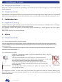
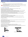
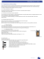
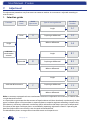
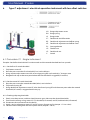
USER MANUAL
PRESSURE SWITCHES
AND TEMPERATURE SWITCHES
P Series
www.georgin.com
User Manual - P series
I.
Introduction
3
1.
2.
3.
4.
5.
Purpose
Operating principle
Pressure Equipment Directive (PED)
Qualified equipment in accordance with RCC-E
General information concerning functions
3
3
3
4
4
II.
Before installation
5
1.
2.
Storage
Before installation
5
5
III. DOs and DON'Ts
6
1.
2.
3.
4.
6
7
8
8
General Recommendations
Special recommendations
Prohibited actions
Advice
IV. Commissioning
9
1.
2.
Mounting the housing
Mounting
9
10
V.
Adjustment
12
1.
2.
3.
4.
Selection guide
Equipment required
Pre-adjustment operations (for any type of adjustment)
Type A adjustment : fixed dead band instrument
12
13
13
14
5.
Type B adjustment : adjustable dead band instrument
16
6.
Type C adjustment:electrical operation instrument with two offset switches18
4.1.
4.2.
4.3.
Procedure A1: Single instrument Procedure A2: Diaphragm-actuated differential instrument
Procedure A3: Bellows-actuated differential instrument
5.1.
5.2.
5.3.
Procedure B1: Single instrument
Procedure B2: Diaphragm-actuated differential instrument
Procedure B3: Bellows-actuated differential instrument
6.1.
6.2.
6.3.
Procedure C1 : Single instrument
Procedure C2: Diaphragm-actuated differential instrument
Procedure C3: Bellows-actuated differential instrument
14
15
15
16
17
17
18
19
19
VI. Wiring
20
1.
2.
3.
4.
5.
20
20
20
21
21
The electrical switch
Cable inlets
Internal terminal blocks
Breaking capacity (resistive circuits)
The pneumatic switch
VII. Maintenance
22
1.
2.
22
23
2
Inspection frequency
Precautions to take during maintenance
www.georgin.com
User Manual - P series
I.
Introduction
You have just acquired a GEORGIN instrument that has undergone extensive testing and several quality
checks to ensure your complete satisfaction.
Appropriate specification, according to your process, and compliance with the instructions in this manual will
ensure an optimum working life for your instrument.
1.
Purpose
P Series instruments are intended for process monitoring.
This manual gives the assembly and configuration instructions to be applied for optimum operation of your
instrument. You must read and obey these instructions when installing your instrument.
!
2.
Never tamper with components of the instrument that are immobilised with red varnish.
Any damage caused by a failure to obey these instructions will invalidate the manufacturer's
guarantee.
Operating principle
VG: Range adjustment screw
RG: Range spring
IG:
Range index
IE : Dead band and offset index
RE: Dead band adjustment and offset spring
VE: Dead band adjustment and offset screw
ES: Sensing element
LP: Flexible arm
LE: Dead band arm
C:
Switch
The pressure or temperature is applied to the sensing element (ES), whose position then changes, acting on
the flexible arm (LP). The force produced in this way is balanced by the spring (RG). This is how the set point is
adjusted. As the set point is approached, the change in forces disturbs the balance and acts on the contact.
A second spring (RE) acting on the end of the flexible arm (LP) increases the deviation of the switch(es). The
force produced by the dead band spring is adjustable, and is used to offset the two contacts in the case of
differential functions.
NOTE: The pressure switch and temperature switch scales indicated in our catalogue are values for a set point
to lower the pressure or temperature.
3.
Pressure Equipment Directive (PED)
Series P pressure and temperature switches satisfy the requirements set forth in Appendix I of PED 2014/68/EU. They
are classified in Category IV as a safety accessory, and can be incorporated in a safety loop. Refer to our declaration of
compliance for the models concerned and conditions of use.
www.georgin.com
3
User Manual - P series
4.
Qualified equipment in accordance with RCC-E
The pressure switches and temperature switches of the P series meet the design and construction rules for electrical
equipment of nuclear plants.
Refer to the equipment identification sheet (according to the last index NTP N 100 – consult us) for a definition,
installation rules and recommendations for maintenance of the equipment in accordance with the associated quality
and general requirements.
5.
General information concerning functions
The instruments may be equipped with electrical or pneumatic functions.
5.1.
Electrical functions
Note:
The dead band values given in our catalogues are indicative values recorded in a laboratory, measured
between the maximum and minimum settings. If the instrument is used outside its operating limits, the set
point(s) and dead band values may be affected.
The electrical operation of the instrument differs according to the type of microswitch used. Many different
versions are on offer (gilt, tropicalised, nitrogen sealed, etc.).
5.1.1. Single fixed dead band electrical operation:
Microswitch “only“. Each type of microswitch has its own characteristics, as indicated in the catalogue.
Models: 4, 4D, 10, 10D, 16, 16D, 8, 98, 60, 60C, ...
5.1.2. Single adjustable dead band electrical operation:
Microswitch combined with a spring (RE) to increase the microswitch dead band value in a given range
(refer to the dead band table in the catalogue)
The trigger value of the upper threshold can be offset using the RE.
This action has no effect on the lower threshold.
Models: 6, 6V, 96, 62, 62C, ...
5.1.3. Electrical operation with two simultaneous contacts:
Combination of two single functions set to act at the same time, either upwards or downwards. The dead band of a
simultaneous function is greater than that of a single function. When rolling out from the factory, the simultaneity is
wedged to the decrease of pressure / temperature.
Fixed dead band models: 44, 30, 36, 38, 108, 160, 160C, ...
Adjustable dead band models: 34, 34V, 106, 162, 162C, ...
5.1.4. Electrical operation with two offset contacts:
Combination of two single functions adjusted to act with a gap between. The spring (RE) is used to adjust the gap
between the interlocking of the switches.
Models: 46, 54, 54V, 50, 56, 116, 118, 172, 172C, 170, 170C, ...
5.1.5. Electrical operation with manual reset:
Once triggered, the switch returns to its initial position only if you press the button located on the side of the housing,
and only if the pressure or temperature has dropped (type 18 max. cut-off device) or climbed
(type 20 min. cut-off device) beyond the set point.
4
www.georgin.com
User Manual - P series
For temperature switches, the minimum dead bands given in our manuals are recorded under ideal
test conditions. The sensing element experiences the temperature variations of the installation without
delay and in its bulk. In operation, these dead bands can be different in view of the exchange conditions:
rate of temperature change, specific heat, radiation, inertia of the measuring instrument compared to
inertia of temperature switch, presence of a sleeve or immersion sleeve, etc.
!
5.2.
Pneumatic functions
The instruments can be equipped with a Normally Open (NO) or Normally Closed (NC) pneumatic function using a
poppet or spool valve.
The supply fittings are M5, 1/4, or 1/8 gas threaded according to the type of function or the model.
According to the type of cell, the control pressure will be:
-- As standard: 1.5 to 8 bar (poppet design <> with a residual leak).
-- On request: 0 to 10 bar (spool design <> without leak).
The control fluid must be compatible with the ISO‑VG 10 standard (air, nitrogen, etc.).
Maximum allowable filtration 5 µm.
The standard materials for the cell body are polyamide, brass, and/or aluminium. The seals are made of NBR
(other types on request).
II.
Before installation
1.
Storage
The pressure switch or temperature switch must be stored in a sheltered location, in its original packaging.
The storage temperature must be between:
-40 and +70°C for bellows instruments
-20 and +70°C for diaphragm pressure switches
-40 and +55°C for temperature switches from the C, G and M ranges
They must not be stacked to reach a load greater than 10 kg.
2.
Before installation
Allow the instrument to return to ambient operating temperature before installing it.
Whilst removing the packaging, check the equipment and all accessories.
The housing must be examined to check the following points:
Check that the paint has not been damaged.
Check that there are no signs of deformation or impact on the housing.
For instruments equipped with an immobilising bolt for transport (located in the instrument's process fitting),
remove this item.
!
1.
2.
3.
For ML/DML instruments:
Loosen the locknut and the immobilizing bolt inserted in the fitting.
Connect the instrument to a pressure bench on the HP side, and apply a pressure of 150 mbar. Return to
atmospheric pressure, and disconnect the instrument from the bench.
Rest the instrument for 24 hours before calibrating.
Before installation check again that the materials in contact are compatible with the process to be monitored.
If necessary, protect the instrument with a safety device that is appropriate to the application (pressure limiter,
shock absorber, thermowell).
www.georgin.com
5
User Manual - P series
III.
DOs and DON'Ts
1. General Recommendations
1.1. Operating temperature limits (pressure sensing element)
Bronze bellows:
Stainless steel bellows:
Stainless steel tube:
NBR diaphragm:
EP diaphragm:
FKM diaphragm:
-20 to +60°C
-20 to +150°C
-20 to +150°C
-20 to +100°C
-40 to +120°C
0 to +150°C
/!\ For temperature switches, refer to the range tables. /!\
1.2. Ambient operating temperature limits (housing)
-20 to 70°C (except temperature switches from the C, G and M ranges: max.55°C) - others on request.
1.3. Radiant heat
Avoid installing the instrument near (radiant) heat sources. Observe the ambient operating temperature limit.
1.4. Pulsations
A suitable shock mount or flexible piping connection must be provided to protect bellows instruments in case of
vibrations or process instability (possible use of PA-type pressure switches).
1.5. Steam
A siphon must be placed upstream from the pressure switches on a steam circuit to limit the temperature
at the sensor.
1.6. Condensation
Protect from excessive sunlight to limit the effects of night-time condensation. The installation location must be chosen
very carefully in seaside locations or damp environments.
1.7. Vibrations
Georgin recommend avoid mounting the instrument directly on vibrating equipment.
Otherwise, an effective anti-vibration system, fully suitable for installation (assembly type, process connection,
electrical connection, ...) and its environment, must be chosen.Flexible piping connections and silent blocks may
sometimes be necessary.
The effectiveness of this mounting must be checked after installation.
6
www.georgin.com
User Manual - P series
1.8. Mounting the housing (see Chapter IV.1)
Georgin recommends mounting the housing in accordance with the following rules:
a. For bellows or Bourdon tube pressure switches and temperature switches:
The orientation of the housing has little effect on the operation of the instrument, but an upright (vertical)
position is nevertheless recommended (with adjustment screw facing upwards). This prevents premature wear
and preserves the measurement characteristics.
b. For diaphragm pressure switches:
Diaphragm instruments (except PA type) MUST be mounted vertically (with adjustment screw facing upwards),
with the diaphragm horizontal, on an appropriate mount.
Because of the weight and/or the shape of the sensing element, the housing of these instruments must NEVER
be used as a mount.
1.9. Installation (see Section IV.2)
The instruments are mounted according to type. Refer to the specific dimensional drawings.
For pressure switches, if the pressure connection uses a rigid tube, ensure that this tube is aligned with the axis
of the fitting so that the housing, and the measuring element in particular, are not subject to any mechanical
loads that could deform them or shift the threshold.
2. Special recommendations
2.1. ATEX devices
For ATEX devices, it is ESSENTIAL to refer to the “ATEX Instruction Manual“ supplied with the equipment and available
on www.georgin.com.
2.2. Low- and medium-pressure instruments
Diaphragm-actuated instruments (except PA type) must be installed with the diaphragm horizontal and secured to a
special mount.
Ask us for further information.
2.3. Differential pressure switches
To ensure that the contact(s) will change state, the pressure in the HP chamber must be greater than that in the LP
chamber. This difference must be greater than the sum of differential pressure (∆P) + microswitch dead band
HP – LP > ∆P + e
Type
Scale ∆P
bar
DPB.QX11
0.5 to 1.5
Adjustable dead band ≤
1x SPDT
2x SPDT
96
106
bar
bar
B
H
B
H
1.2
1.8
Max.
dead
band ≥
bar
2
Max. P
static
bar
Min / Max
2.5 / 33
Example: For a DPB.QX11 in function 96, the pressure in the HP chamber must be greater than the pressure in
the LP chamber by at least:
P. HP – P. BP > 0.5 + 1.2 bar
P. HP – P. BP > 1.7 bar
www.georgin.com
7
User Manual - P series
2.4. Bourdon tube instruments (PL/PLB sensors)
When the instrument is mounted on rigid fittings, ensure that the mount does not apply any residual loads to the
process connector.
2.5. Temperature switches
Any difference in level between the housing and the probe must be taken into account. Where necessary, to inhibit the
effect of the height of the liquid column, the calibration values may need to be corrected (for more information, ask us).
3. Prohibited actions
3.1. Integrity of the housing
To avoid compromising the mechanical properties of the enclosure and invalidating its qualification level, no drilling or
machining must be performed on these measuring instruments.
Gas throttling surfaces (seal planes) are kept clean, lightly lubricated (e.g. silicone grease) and free of dents
or scratches.
Add-on seals and paint are strictly prohibited.
4. Advice
4.1. Temperature switches
4.1.1. Devices equipped with an immersion sleeve
For bulbs implanted in immersion sleeves (except perforated immersion sleeves) for gaseous fluid applications,
a thermal bridge must be created between the bulb and the immersion sleeve using a filler liquid (oil) or a heatconducting paste.
/!\ Caution: Ensure that the quantity of liquid or paste is not excessive, to avoid compressing the bulb, but is
sufficient to cover it completely. /!\
4.1.2. Orientation of the probe
ESSENTIAL: Thermostatic probes must be installed facing down, with the
capillary outlet at the top.
The measurement probe must not be placed in a horizontal position.*
Our temperature switches consist of two main components: probe and
housing, which might or might not be connected by a capillary.
The position of the probe can affect the operation of the temperature
switch. This type of probe is intended for vertical use, and is placed lower
than the housing.
Any deviation from these conditions can affect the response time and
operation of the device.
Our temperature switches are built with a filling that allows the probe to be tilted 45° without affecting their
operation. Beyond that, their operation depends on the value of the measured temperature compared to the
ambient temperature.
8
www.georgin.com
User Manual - P series
Recommended area:
±45° either side of the vertical axis, bulb down (capillary output up).
Area to be avoided:
from 45° to 75°, the operation of the sensor depends on the measured
temperature value (Ts) and the ambient temperature (Ta):
Ta > Ts: operation is not affected,
Ta < Ts: operation might be affected,
Ta = Ts: operation is affected.
*Prohibited area
Beyond 75°, the operation of the sensor can be significantly affected.
This is difficult to predict and depends on several physical parameters.
Technical solutions are possible on request (ask us).
IV.
Commissioning
1. Mounting the housing
1.1. Bellows, Bourdon tube, and PA diaphragm pressure switches, and temperature switches
¾¾ The wall mount must be installed using two Ø 5 mm screws, Class 8.8
¾¾ The housing must be secured to its mount and immobilised with screw V (2.5 N∙m)
¾¾ The cover must be closed using the two captive screws (1.2 Nm).
V: mounting screw
Dimensions in mm.
1.2. Diaphragm pressure switches (except PA type)
These instruments are supplied without a wall mounting plate. Use the following mounting methods:
(D)ML(B): Use the four spacers provided around the edge of the sensing element.
(D)MABV - DMKBV:
Use the two M10 threads provided under the sensing element.
(D)MJBV - (D)MPB:
Use the two M6 threads provided under the sensing element.
We also provide special mounting brackets for the purpose. Ask Georgin for further information.
www.georgin.com
9
User Manual - P series
2. Mounting
!
Avoid mounting on a vibrating wall. This may result in a premature electrical malfunction.
It is especially when approaching the changeover thresholds that our devices are particularly sensitive to
certain vibration frequencies.
If no other mounting is possible, we recommend the use of elastic suspensions for any use on a vibrating
wall, especially in the case of a slow evolution of the pressure or temperature.
2.1. Pressure switch mounting
The instruments are equipped with a 1/2’’ GM or 1/4’’ GF (to ISO 228-1) fitting as standard.
Other fittings on request (NPT connection to ASA B2-1).
Optional connection by soldered tab (see fc-a3500-fren).
To make the connections, use the appropriate spanners for the fittings, and never use the housing to tighten.
Recommended tightening torque for the pressure fitting: 50 N∙m for the 1/2’’ GM.
Check that the pressure inlet tubes are not applying any mechanical load to the fitting and the housing.
Observe the environmental and fluid-related conditions corresponding to the characteristics of the instruments.
Provide tubing or a capillary to avoid any overheating through conduction.
Never exceed the maximum pressure of the instrument indicated on the label on the side of the housing.
2.1.1. Monitoring liquid pressure :
The pressure switch must be installed under the pressure fittings.
The pipework must be installed in a way that prevents any accumulation of gas in the pressure switch.
The installation of a gas collection tank is recommended.
The pipes connecting the process to the pressure switch must have a descending slope of at least 1/10 to
prevent gas accumulation.
2.1.2. Monitoring gas pressure :
The pressure switch must be installed above the pipes to prevent condensation in the connection pipes and the
pressure switch measurement chambers.
If the gas temperature is high, a cooler or a siphon may be used.
The pipes connecting the process to the pressure switch must have a rising slope of at least 1/10 to prevent
the accumulation of liquid or condensates.
2.1.3. Monitoring the vapour pressure :
The pressure switch may be installed laterally or under the pressure fittings.
A condensate vessel must be installed between the pressure switch and the pressure fitting.
The pipe or pigtail siphon (see fc-a3000-fren) connecting the condensate vessel to the pressure switch must be
filled with water beforehand.
A bleeder valve must be installed.
Lateral installation
10
www.georgin.com
Installation under the pressure fitting
User Manual - P series
2.2. Temperature switch mounting
Observe the environmental and fluid-related conditions corresponding to the characteristics of the instruments.
Never exceed the maximum temperature of the instrument indicated on the label on the side of the housing.
A capillary introduced into the liquid can be of any length.
2.2.1. Direct probe device (Type B) :
Secure the instrument via its fitting (on G 3/8" thread as standard, other on request).
Completely immerse the probe.
2.2.2. Ambient monitoring instrument (Type BA) :
The instrument must be installed in a well ventilated location, away from heat sources or refrigerant devices. It must
not be subjected to sudden temperature changes.
For monitoring in inhabited buildings, install the temperature switch 1.50 m above the floor and far from
external walls.
2.2.3. Remote probe device (Type C) :
Do not constrain the capillary. It must remain flexible to transmit the signal.
Roll the capillary with a diameter of at least 80 mm.
NOTE: In certain cases, the size of the bulb and the length of the capillary can be specified in the order.
a. Monitoring fluids
Completely immerse the probe.
Use an appropriate type GBX or GCX immersion sleeve immersed perpendicular to the flow, or use
a PC(X)**(B) capillary cable gland according to the existing process fitting type.
b. Monitoring surfaces
Carefully clean the contact surface and the probe.
Secure the probe using a metal (preferably cuprous) collar, covering the
length of the probe.
Add thermal insulation on top.
Take care to observe the probe orientation (see Chapter III - 4..1.2)
Thermal insulation
Copper alloy flange
2.2.4. Accessories :
Capillary cable gland kit:
If the capillary outlet must be sealed, use our special PC(X) type cable gland.
• Slide nut E onto the capillary.
E
• Secure sleeve M on the thread (1/2"GF, NPTF, etc.).
R
• Insert two washers R in sleeve M, inverting the notches.
G
• Insert gasket G, consisting of five (or six, according to model) Teflon washers.
• Insert the other two washers like the first two.
R
• Tighten nut E onto sleeve M.
M
For further information, ask us.
www.georgin.com
11
User Manual - P series
V.
Adjustment
The adjustment procedures vary from one instrument to another. An instrument is adjusted according to
several criteria.
1. Selection guide
Type of sensing element
Procedure
Number
Single
A1
Diaphragm differential
A2
Single
Bellows differential
A3
with two
simultaneous
contacts
Single
B1
Diaphragm differential
B2
Bellows differential
B3
Single
C1
Diaphragm differential
C2
Bellows differential
C3
Function
Dead
band
Fixed
Adjustable
with two offset contacts
Model
adjustment
A
B
C
Note: Instruments equipped with two simultaneous contacts are adjusted in the same way as devices with
a single electrical function.
It is impossible to guarantee that the contacts of bipolar devices will close absolutely simultaneously on the
upper and lower points. If that condition is required, choose a unipolar regulator controlling a bipolar relay.
If the device is not factory calibrated, simultaneity will be achieved on the drop in pressure or temperature.
The values of the upper and lower points are modified by operating adjustment screw VG. Operating the
dead band adjustment screw VE only varies the peak or the dead band.
The identification plates are engraved to show both metric and Imperial units.
12
www.georgin.com
User Manual - P series
VE
VG
Clockwise:
Increases the set point and/or dead band value.
Anticlockwise:
Lowers the set point and/or dead band value.
Note: for RTPE type, the dead band adjustment screw VE is
internal to the housing.
2. Equipment required
»» A 1% class calibration standard:
-- For pressure switches: a pressure gauge
-- For temperature switches: a thermometer
»» A pressure or temperature generator:
-- For pressure switches: an air generator for pressures from -1 to 80 bar;
Hydraulic for pressures from 80 to 1000 bar
For temperature switches: a thermostatic bath
The coolant fluid must be appropriate for the temperatures concerned (e.g. water-glycol
from -20 to 0°C).
An electric low level system (1 ohmmeter + 1 buzzer + indicator light) - powered at 24 V ≈
-»»
3. Pre-adjustment operations (for any type of adjustment)
»» Loosen the two captive screws holding the cover, and then remove it. Perform a visual inspection
of the instrument.
»» Install the instruments:
-- For pressure switches: connect the instrument to a pressure bench
-- For temperature switches: immerse the bulb(s) in the bath
»» The range (RG) and dead band (RE) springs, if the instrument has any, must be fully extended.
»» Connect the terminal(s) to the electrical system.
For pressure switches, the pressure change when approaching the thresholds will be approximately:
»» For a threshold < 2.5 mbar: ≤ 0.025 mbar/min
»» For a threshold < 10 mbar: ≤ 2.5 mbar/min
»» For a threshold < 100 mbar: ≤ 3.5 mbar/min
»» For a threshold > 100 mbar: ≤ 5% EM/min
For temperature switches, the temperature change will be approximately 0.5°C/min.
Note: The following procedures describe the steps to be applied in order to calibrate pressure switches.
For temperature switches, the procedure is the same as for single or differential bellows-actuated
pressure switches:
-- Adjust in °C.
-- Vary the temperature.
www.georgin.com
13
User Manual - P series
4. Type A adjustment : fixed dead band instrument
VG: Range adjustment screw
RG: Range spring
IG:
Range index
ES:
Sensing element
LP:
Flexible arm
C:
Switch
4.1. Procedure A1: Single instrument
Example: 6-bar rising setting
4.1.1. Adjusting the set point
1.
2.
Raise the pressure to the threshold (6 bar) and stabilise it.
Using set point adjustment screw VG, relax range spring RG until switch(es) C changes state.
4.1.2. Checking/Adjusting the set point
3.
4.
5.
6.
7.
14
Slowly raise the pressure, and then slowly lower it again. Measure the lower and upper triggering thresholds.
Fine-tune the settings using adjustment screw VG (Lower and Upper threshold control).
Disconnect the instrument from the bench.
Apply a seal to adjustment screw VG using a Georgin seal kit (torque: 1.7 N∙m ±10%).
Close the cover and tighten the two captive screws (torque: 1.2 N∙m).
www.georgin.com
User Manual - P series
4.2. Procedure A2: Diaphragm-actuated differential instrument
For reasons related to production and metrology, low- and medium-pressure differential instruments are adjusted
relative to each other, with the LP chamber vented to atmosphere.
The procedure is identical to the procedure described in the previous point (A.1. Single instrument).
The HP chamber is connected to the pressure bench, and the LP remains at atmospheric pressure.
4.3. Procedure A3: Bellows-actuated differential instrument
Example: Lower threshold set to 1 bar falling with 10 bar static pressure.
4.3.1. Setting the lower threshold
1.
2.
3.
4.
5.
Go up to the desired static pressure in both chambers (10 bar), and stabilise.
Isolate both chambers.
Create a pressure differential in favour of the HP chamber equal to the desired threshold value “1 bar“
(HP=10 bar, LP=9 bar).
Using set point adjustment screw VG, relax range spring RG until the exact point when switch(es) C is/are
triggered on the way up.
Retighten and stop at the exact point where switch(es) C is/are interlocked on the way down.
4.3.2. Checking/Adjusting the set points
6.
Repeat operations 1 to 3, and then slowly pressurise and depressurise the HP chamber to measure the
changeover value of the switch(es) on the way down.
7. Fine-tune the setting using adjustment screw VG (Lower and Upper threshold control).
8. Disconnect the instrument from the bench.
9. Apply a seal to adjustment screw VG using a Georgin seal kit (torque: 1.7 N∙m ±10%).
10. Close the cover and tighten the two captive screws (torque: 1.2 N∙m).
www.georgin.com
15
User Manual - P series
5.
Type B adjustment : adjustable dead band instrument
VG: Range adjustment screw
RG: Range spring
IG:
Range index
IE :
Dead band and offset index
RE:
Dead band adjustment and offset spring
VE: Dead band adjustment and offset screw
ES:
Sensing element
LP:
Flexible arm
LE:
Dead band arm
C:
Switch
5.1. Procedure B1: Single instrument
Example: 2 mbar falling and 6 mbar rising.
5.1.1. Setting the lower threshold
1.
2.
3.
4.
Inhibit the dead band spring (RE) by fully loosening the knob (ME).
Raise the pressure to the lower threshold (2 mbar) and stabilise it.
Using set point adjustment screw VG, relax range spring RG until switch(es) C changes state.
Retighten and stop at the exact point where switch(es) C is/are interlocked on the way down.
5.1.2. Setting the upper threshold
5.
6.
7.
8.
Keep the pressure stable at 2 mbar.
Fully extend spring RE.
Raise the pressure to the upper threshold (6 mbar) and stabilise it.
Using dead band adjustment screw VE, relax dead band spring RE until the exact point when switch(es) C
is/are triggered on the way up.
5.1.3. Checking/Adjusting the set points
9.
10.
11.
12.
13.
16
Slowly raise the pressure, and then slowly lower it again. Measure the lower and upper triggering thresholds.
Fine-tune the settings using screws VG (Low threshold control) and VE (High threshold control).
Disconnect the instrument from the bench.
Apply a seal to adjustment screws VG and VE using a Georgin seal kit (torque: 1.7 N∙m ±10%).
Close the cover and tighten the two captive screws (torque: 1.2 N∙m).
www.georgin.com
User Manual - P series
5.2. Procedure B2: Diaphragm-actuated differential instrument
For reasons related to production and metrology, low- and medium-pressure differential instruments are adjusted
relative to each other, with the LP chamber vented to atmosphere.
The procedure is identical to the procedure described in the previous point (B.1. Single instrument).
The HP chamber is connected to the pressure bench, and the LP remains at atmospheric pressure.
5.3. Procedure B3: Bellows-actuated differential instrument
Example: Set the low threshold to 1 bar downwards and the high threshold to 3 bar upwards, and static pressure 10
bar.
5.3.1. Setting the lower threshold
1.
2.
3.
4.
5.
6.
Inhibit the dead band spring (RE) by fully loosening the knob (ME).
Go up to the desired static pressure in both chambers (10 bar), and stabilise.
Isolate both chambers.
Create a pressure differential in favour of the HP chamber equal to the desired low threshold value “1 bar“
(e.g., HP=1 bar, LP=9 bar).
Using set point adjustment screw VG, relax range spring RG until the exact point when switch(es) C is/are
triggered on the way up.
Retighten and stop at the exact point where switch(es) C is/are interlocked on the way down.
5.3.2. Setting the upper threshold
7.
8.
9.
10.
Return to the desired static pressure in both chambers (10 bar), and stabilise.
Isolate both chambers.
Fully extend spring RE.
Create a pressure differential in favour of the HP chamber equal to the desired high threshold value
“3 bar“ (HP=10 bar, LP=7 bar).
11. Using dead band adjustment screw VE, relax dead band spring RE until the exact point when switch(es) C
is/are triggered on the way up.
5.3.3. Checking/Adjusting the set points
12. Repeat operations 2 and 3, and then slowly pressurise and depressurise the HP chamber to measure the
changeover values of the switch(es) on the way up and the way down.
13. Fine-tune the settings using the threshold adjustment screw (VG = Lower threshold and VE = Upper threshold).
14. Disconnect the instrument from the bench.
15. Apply a seal to adjustment screws VG and VE using a Georgin seal kit (torque: 1.7 N∙m) ±10%).
16. Close the cover and tighten the two captive screws (torque: 1.2 N∙m).
www.georgin.com
17
User Manual - P series
6.
Type C adjustment : electrical operation instrument with two offset switches
VG: Range adjustment screw
RG: Range spring
IG:
Range index
IE :
Dead band and offset index
RE:
Dead band adjustment and offset spring
VE: Dead band adjustment and offset screw
ES:
Sensing element
LP:
Flexible arm
LE:
Dead band arm
C:
Switch
6.1. Procedure C1 : Single instrument
Example: Set the first threshold to 5 bar downwards and the second threshold to 6 bar upwards.
6.1.1. Set the first LP switch threshold.
1.
2.
3.
4.
Fully loosen screw VE.
Raise the pressure to the first threshold (5 bar) and stabilise it.
Using set point adjustment screw VG, relax range spring RG until switch(es) C changes state.
Retighten and stop at the exact point where the first threshold is triggered (LP contact).
6.1.2. Set the second HP switch threshold.
5.
6.
7.
Raise the pressure to the second threshold (6 bar) and stabilise it.
Fully extend spring RE.
Using dead band adjustment screw VE, relax dead band spring RE until the exact point when the second
threshold (HP switch) is triggered on the way up.
6.1.3. Checking/adjusting thresholds
8.
9.
10.
11.
12.
18
Slowly raise the pressure, and then slowly lower it again. Measure the desired thresholds.
Fine-tune the settings using screws VG (1st threshold, LP control) and VE (2nd threshold, HP control).
Disconnect the instrument from the bench.
Apply a seal to adjustment screws VG and VE using a Georgin seal kit (torque: 1.7 N∙m ±10%).
Close the cover and tighten the two captive screws (torque: 1.2 N∙m).
www.georgin.com
User Manual - P series
6.2. Procedure C2: Diaphragm-actuated differential instrument
For reasons related to production and metrology, low- and medium-pressure differential instruments are adjusted
relative to each other, with the LP chamber vented to atmosphere.
The procedure is identical to the procedure described in the previous point (C.1. Single instrument).
The HP chamber is connected to the pressure bench, and the LP remains at atmospheric pressure.
6.3. Procedure C3: Bellows-actuated differential instrument
Example: Set the first threshold to 1 bar downwards and the second threshold to 5 bar upwards, with static pressure
10 bar.
6.3.1. Set the first LP switch threshold.
1.
2.
3.
4.
5.
6.
Inhibit the dead band spring (RE) by fully loosening the screw (VE).
Go up to the desired static pressure in both chambers (10 bar), and stabilise.
Isolate both chambers.
Create a pressure differential in favour of the HP chamber corresponding to lowering the first required
threshold “1 bar“ (HP=10 bar, LP=9 bar).
Using set point adjustment screw VG, relax range spring RG until the exact points when the two switches
are triggered on the way up.
Retighten until the exact point where the first threshold is triggered on the way down (LP switches).
6.3.2. Set the second HP switch threshold.
7.
8.
9.
10.
Return to the desired static pressure in both chambers (10 bar), and stabilise.
Isolate both chambers.
Fully extend spring RE.
Create a pressure differential in favour of the HP chamber equal to the second desired high threshold
value “5 bar“ (HP=10 bar, LP=5 bar).
11. Using dead band adjustment screw VE, relax dead band spring RE until the exact point when the second
threshold is triggered on the way up (HP switch).
6.3.3. Checking/adjusting thresholds
12. Repeat operations 2 and 3, and then slowly pressurise and depressurise the HP chamber to measure the
changeover values of the switches on the way up and the way down.
13. Fine-tune the settings using the threshold adjustment screw (RG = 1st threshold and RE = 2nd threshold).
14. Disconnect the instrument from the bench.
15. Apply a seal to adjustment screws VG and VE using a Georgin seal kit (torque: 1.7 N∙m ±10%).
16. Close the cover and tighten the two captive screws (torque: 1.2 N∙m).
www.georgin.com
19
User Manual - P series
VI.
Wiring
1. The electrical switch
NO
C
Resting state of the switch(es) :
At rest, contact is established between C-NC.
According to the type of action (opening or
closing of the electrical circuit), make the electrical
connection on the terminal block between C-NC
or C-NO.
Position above the threshold
NC Position below the threshold
2. Cable inlets
The instruments (except explosion-proof housings) are supplied with one or two M20 cable glands
For Ø 7.5 to 13 mm cable (standard instrument)
For Ø 8 to 13 mm cable (S.I. and Ex de instrument)
Other cable gland models are available on request.
The instrument can also be supplied without cable inlets. In that case, the instrument is supplied with an
M20 thread as standard. The cable gland must be mounted according to the attached datasheet.
Explosion-proof housings: the housing is supplied as standard with a type 3/4"NPT cable inlet. Cable
glands are available as an option. The choice of cable gland directly affects the certification, and could lead
to the equipment being declassified. Refer to the ATEX instruction sheet. The cable gland must be mounted
according to the attached datasheet. Apply graphite grease on the cable entry threading before tightening
the cable gland.
Ensure that the cable gland has been tightened sufficiently, and add 'drip protection' to the cable in order to
preserve the instrument's IP level.
3.
Internal terminal blocks
The terminal blocks are designed for the following maximum wire size: 2.5 mm² for standard models and 1.5 mm² for
ATEX models.
Contact No.2
Standard contacts
4 / 6 / 8 / 10 / 16 / 20 (D) (T)
34 / 54 / 38 / 58 (D) (T)
18 (D)
Nitrogen sealed contacts
96 / 98
106 / 116 / 108 / 118
Explosion-proof contacts
60 (D)
160 / 170 (D)
62 (D)
162 / 172 (D)
Cable outlet explosion-proof contacts
60C
160C / 170C
62C
162C / 172C
Contact No.1
NC
C
NO
NC
C
NO
•
blue
•
•
red
•
•
white
•
blue
blue
white
red
red
red
white
white
blue
•
red
•
white
•
green
red
red
white
white
green
green
•
4
•
2
•
1
•
1
•
2
•
4
4
4
2
2
1
1
1
1
2
2
4
4
•
brown
•
grey
•
white
•
black
•
green
•
brown
brown
brown
grey
grey
white
white
black
black
green
green
brown
brown
For specific electrical connections, refer to the associated technical drawings.
Housing closure (except explosion-proof housings) :
To preserve the instrument's ingress protection (IP) index, the cover must be closed and tightened to the
following torque: 1.2 N∙m.
20
www.georgin.com
User Manual - P series
4.
Breaking capacity (resistive circuits)
4.1. Breaking capacities
Contact No.
4/44
6/8/18/20/34/38/54
10/16/30/36/50/56
96/106/116/98/108/118
92/102/112
62/62C/162/162C/172/172C
60/60C/160/160C/170/170C
4D/44D/46D/ 6D/34D/54D
8D/10D/30D/38D/50D/16D/36D/56D
18D/20D
AC
10A
5A
2A
2.5A
4A
5A
7A
-
240V
240V
240V
240V
115V
240V
240V
-
DC
0.5A
0.5A
1A
1A
0.3A
0.4A
0.25A
1mA / 100mA
10mA / 100mA
10mA / 100mA
110V
130V
130V
130V
110V
250V
250V 6V
4V / 30V
6V / 24V
6V / 24V
IMPORTANT
Intrinsic Safety certified instruments (Ex ia) are equipped with gold-plated contacts. These instruments must
be interfaced via an Intrinsic Safety relay. Georgin recommends the RDN model - see fc-rdn-fren on
www.georgin.com.
The explosion proof switches with cable output must be imperatively connected to an approved terminal
block and a junction box.
4.2. Breaking capacity limits
Gold-plated contacts
Minimum threshold
18D and 20D
10 mA - 6 Vdc
6D, 34D, 54D, 4D, 44D and 46D 1 mA - 4 Vdc
Other gold-plated contacts
10 mA - 6 Vdc
Standard contacts: Never use below 100 mA - 24 VAC.
Maximum threshold
100 mA - 24 Vdc
100 mA - 30 Vdc
100 mA - 24 Vdc
Never operate or test the
instrument above the
maximum threshold.
5. The pneumatic switch
Labelling of the cell connections:
NO operation
NC operation
A
A
U
U
E
Pression/Température
A : Power supply
E
Pression/Température
E : Exhaust
U : Use
For certain models, exhaust is via open cable gland or screw terminal (mandatory for ATEX models).
The control pressure applied to the unit affects the dead band at a given set point: the lower the supply
pressure, the smaller the dead band, and vice-versa.
www.georgin.com
21
User Manual - P series
VII.
Maintenance
1. Inspection frequency
Inspection frequency depends on several criteria:
»» The mechanical and/or electrical working life of the microswitch
»» The mechanical working life of the sensing element
»» Frequency and conditions of operation of the instrument
Georgin's standard* recommendation is to proceed as indicated:
1. Visual inspection of the instrument
(See Chapter II. Before installation)
2. Calibration
0
1
1. Visual inspection
2. Check cover seal
3. Checking / adjusting the calibration
6
1. Visual inspection
2. Check cover seal
3. Checking / adjusting the calibration
1.
2.
12
Years
1. Replacement to
be considered after
complete inspection
»» Year 0 :
Check that the paint has not been damaged, and check that there are no signs of deformation or impact
on the housing.
Calibration:
If the instrument is supplied adjusted: Check that the calibration is compliant, and readjust if necessary.
If the instrument is supplied unadjusted: Calibrate it according to the procedures given in this manual.
»» Year 1 :
1.
2.
3.
After one year of standard operation, the mechanism can be considered to be run in. The following points
must therefore be checked:
Check that the paint has not been damaged, and check that there are no signs of deformation or impact
on the housing.
Open the cover and check that the cover seal is not damaged (cracks, etc.)
Check the calibration and adjust if necessary (applying the procedures given in this manual).
»» Year 6 :
1.
2.
3.
22
After six years of standard operation, perform another inspection to ensure that the instrument is ageing well.
Check that the paint has not been damaged, and check that there are no signs of deformation or impact
on the housing.
Open the cover and check that the cover seal is not damaged (cracks, etc.)
Check the calibration and adjust if necessary (applying the procedures given in this manual).
www.georgin.com
User Manual - P series
»» Year 12 :
After 12 years in standard operation, Georgin recommends sending the instrument to our After Sale
Service department for diagnosis. This may lead to some components being replaced or the instrument
being scrapped.
After 12 years of operation, an annual inspection must be performed.
Note: Beyond 20 years of operation, no further repairs will be carried out. The instrument will always be
scrapped in the event of failure.
*In view of the many and varied possible uses on industrial sites, the maintenance frequency must be
increased in case of heavy-duty operation or harsh conditions.
For example:
-- High rate > 4 cycles/minute
-- Corrosive or crystalline fluid or environments
!
Instruments in safety roles must be inspected annually.
2. Precautions to take during maintenance
The instrument must be disassembled WHEN DISCONNECTED FROM POWER, using an appropriate spanner for the
fitting.
GEORGIN guarantees the qualification of the equipment that leaves the factory. Any operation performed on
the equipment other than adjusting the instrument releases GEORGIN from all liability in the event of failure.
In the event you suspect a failure or permanent fault, return the equipment to our offices or our
representatives, who are the only maintenance providers certified to perform expert assessments or repairs.
Any equipment returned MUSTbe accompanied by an After Sale Service return form. This can be obtained
from www.georgin.com (look under download/After Sale Service) and must be duly completed and signed.
www.georgin.com
23
fu-p-en-11/01/2019
Subject to modifications due to technical advances
“Designed, developed and manufactured in France“
GEORGIN Regulators
France
14-16, rue Pierre Sémard - BP 107 - 92323 CHATILLON Cedex France
Tel.: +33 (0)1 46 12 60 00 - Fax: +33 (0)1 47 35 93 98 - Email: [email protected]
Belgium
Temselaan 5 - 1st floor - 1853 STROMBEEK-BEVER
Tel: +32 (0)2 735 54 75 - Fax: +32 (0)2 735 16 79 - Email: [email protected]
www.georgin.com


![2013 Gun List internet copy[2]](http://vs1.manualzilla.com/store/data/005851443_1-16b4e1bd3fc391c408d2005c48a2e336-150x150.png)