1
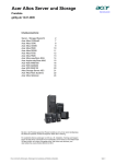
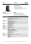
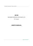
Model ASC3N
Absolute Serial Interface Card
USER'S MANUAL
Third Edition
Gurley
Precision Instruments
May 1999
514 Fulton Street, Troy, NY 12181 USA
Phone:
(518) 272-6300
Toll free:
(800) 759-1844
Fax:
(518) 274-0336
URL:
[email protected]
Table of Contents
Introduction
Overview
3
How to Use This Manual
5
Package Contents
6
What Else You Will Need
7
Configuring and Installing your ASC3N
Avoiding Configuration Conflicts
7
Configuring the ASC3N
10
Installing Your ASC3N
15
Connecting the ASC3N to the A25S Encoder
16
Using Multiple ASC3N’s in Your Computer
16
Software Installation
Device Drivers
19
Utility Programs for Test and Evaluation
19
Writing Application Programs
Address Usage and Status Register
22
C Language Example
25
Quick Basic Language Example
27
MS Visual Basic Language Example
28
Problems and Solutions
General Troubleshooting
29
Appendices
2
Appendix A
Specifications
31
Appendix B
Configuration Jumper Summary
32
Appendix C
Glossary
33
Appendix D
Warranty and Return Policy
35
Overview
The Model ASC3N absolute serial interface card is designed for the IBM AT (minimum)
with 16-bit ISA bus architecture and most compatible computers. PC-based applications
that require positional data or feedback can now use the ASC3N along with a GPI Model
A25S absolute rotary encoder to accomplish this. The ASC3N interface card enables you
to control from one to three encoders, configured with serial data outputs, right from your
computer. The ASC3N provides all of the necessary signals to interrogate and read in the
data from the encoder(s).
The ASC3N and A25S transmit and receive data serially by RS-422 line drivers and
receivers. The A25S requires an active low interrogate pulse to initiate a rotary to digital
conversion. The ASC3N generates this signal, and sends it on a separate line
simultaneously to each of the three encoders. When each encoder has converted rotary
position into digital data, the ASC3N starts reading and shifting the serial data into its onboard shift registers. The shift/read clock is generated for all three channels in unison.
The rate at which the data is transmitted to the ASC3N is configurable by the user with
jumpers located on the ASC3N. Parameters such as the quality and length of the
transmission line and application timing requirements will affect the maximum baud rate
allowable. The baud rate can be from 28 kHz to 3.6 MHz. This corresponds to data
update rates of from 1,000 to 100,000 encoder reads per second. Also configurable via
jumper is the data size and parity. Data size is from 14 bits to 17 bits and parity can be
even or odd. It is important that when more than one encoder is used with the ASC3N,
the data size and parity be configured alike.
The ASC3N checks the parity of the incoming data and reports any errors to the status
register which can be polled. A busy signal bit in the status register or an interrupt request
signal indicates to the computer if all of the data has been received by the ASC3N and it
is ready to be read. A simple I/O read from the computer will input the 16-bit data
word(s) from the ASC3N to the CPU.
Figure 1 illustrates typical short haul connections from the Model A25S absolute encoder
to the ASC3N interface card using the computer's power supply to power the encoders.
Figure 2 shows typical long haul (beyond 50 feet) connections with separate encoder
power sources located within 50 feet of the encoders. See the A25S data sheet for
additional supply recommendations, and section 2.4 for cabling details.
3
Figure 1 - Block Diagram of Short Haul Connections
Figure 2 - Block Diagram of Long Haul Connections
4
How to Use This Manual
This section lists the steps for installing and configuring your ASC3N Absolute Encoder
Serial Interface Card in the order in which they must be performed. It also tells you
where to go in the manual for detailed instructions.
1. Read sections 1.3 "Package Contents" and 1.4 "What else you will need". Be sure you
have all of the necessary hardware and software before continuing.
2. Read section 2.1 "Avoiding Configuration Conflicts". Although, for most
installations, the default factory settings for the ASC3N will not create configuration
conflicts, it is important that you be aware of the settings commonly used by other
devices and computer functions.
3. Configure the ASC3N. Go to section 2.2 "Configuring the ASC3N".
4. Install the ASC3N in your computer. Go to section 2.3 "Installing Your ASC3N".
5. Connect the ASC3N to the model A25S Absolute Rotary Encoder. Go to section 2.4
"Connecting the ASC3N to the Model A25S Absolute Rotary Encoder".
6. Install the software drivers. Go to section 3 "Software Installation". It is
recommended that a short haul test cable be fabricated and one or more encoders be
connected to the interface card to verify correct ASC3N configuration, software
installation, and valid encoder behavior. This is helpful to accomplish before tackling
the various potential issues of long haul hook-up including finding the maximum data
transmission rate, proper grounding, RS-422 termination adjustments, etc.
5
Package Contents
Your ASC3N package contains:
•
•
•
•
One ASC3N Absolute Serial Interface Card.
Software Support Diskette.
This User’s Manual.
Warranty and Suggestion Card.
The Diskette contains the following directories:
DOSASC3 directory:
This directory contains the files necessary to run the Test ASC3N programs under the
DOS operating system.
EXAMPLES directory:
This directory contains example routines written in C, Quick Basic and MS Visual Basic
for Windows.
VBASC3 directory:
This directory contains the files necessary to run the Test ASC3N programs under the
Windows operating system.
What Else You Will Need
To use your ASC3N Absolute Serial Interface Card, ensure that the following minimum
hardware and software requirements are met:
•
•
An available 16-bit expansion slot in any IBM AT or compatible computer with an
ISA bus.
One, two or three Model A25S Absolute Encoders configured for serial data output.
For Gurley Test and Demonstration software:
DOS Demo:
•
MS-DOS 3.1+ or PC-DOS.
Windows Demo:
•
•
6
Window 3.xx or Windows 95.
VGA or better video.
Avoiding Configuration Conflicts
The ASC3N is factory preconfigured for an I/O base address of 210 (hex) and the IRQ
level set to none. In most cases this will not conflict with other devices or functions in
your computer. However, it is important that you become familiar with the configuration
settings typically used by other devices and computer functions. This information will aid
in verifying that the preconfigured jumper settings are satisfactory for your installation.
This section provides helpful information for determining which I/O base address and
IRQ level settings you should select for your ASC3N. Read this information carefully.
Input/Output (I/O) Base Address
The I/O base address is used to designate the beginning of address space available for
communication between the computer and its installed devices. The ASC3N requires 16
(10 hex) contiguous I/O addresses. For example, an I/O base address of 220 uses
addresses 220 through 22F (hex).
Table 1 lists I/O base addresses and potential conflicting devices. Column 1 contains all
possible I/O base addresses for your ASC3N. Notice the range is from 200 - 3F0 (hex).
Column 2 lists potential conflicting devices and their typical I/O base addresses. Use this
table as a guide when selecting an I/O base address for your ASC3N. If, for example, you
have a device using I/O base address 220, select an I/O base address other than 220.
Make sure that the address you select is not used by some other device.
All addresses without a description in column 2 are generally available for use. Be aware,
though, that computers with small built-in LED or LCD displays (to show disk cylinder
data or clock speed) may also use address space.
7
Possible I/O
Base Address
200
210
220
230
240
250
260
270
280
290
2A0
2B0
2C0
2D0
2E0
2F0
300
310
320
330
340
350
360
370
380
390
3A0
3B0
3C0
3D0
3E0
3F0
Potential conflicting Devices
and Their Typical I/O Address
Game Controller/Joystick (200-20F)
Expansion Unit (210-217)
Novel NetWare Key Card
COM4: (2E8-2EF) GPIB Adapter 0 (2E1) Data Acquisition (2E2-2E3)
COM2: (2F8-2FF)
Prototype Card (300-31F)
LPT1: (378-37F)
SLDC/Secondary Bi-Sync Interface (380-38C)
Primary Bi-Sync Interface (3A0-3A9)
Monochrome Display (3B0-3BB)
EGA Display Control (3C0-3CF)
Color/Graphics Display - CGA (3D0-3DF)
COM3: (3E8-3EE)
Floppy Disk Controller (3F0-3F7) COM1: (3F8-3FF)
Table 1 - I/O Base Addresses Used by Various Devices
8
Interrupt Level
If interrupts are to be used with the ASC3N, a unique interrupt (IRQ) level must be
assigned to the ASC3N. An interrupt request (IRQ) signals to the computer when a
device needs attention. The ASC3N supports IRQ levels 5, 7, 9, 10, 11 and 15.
Table 2 lists the IRQ levels supported by your ASC3N and the devices that commonly
use those IRQ levels. Column 1 list all of the IRQ levels supported and Column 2 shows
the devices and computer functions in an AT computer that are likely to use them. For
example, the LPT2 port in an AT is likely to use IRQ 5. Therefore, to avoid a conflict,
you should not configure the ASC3N to use IRQ 5 if the LPT2 port is being used in your
AT computer.
The same principle applies to the other IRQ levels shown in Table 2, with the exception
of IRQ 9 and the possible exception of IRQ 7.
Even though EGA and VGA video adapters are installed and potentially can use IRQ 9,
most applications do not; hence, IRQ 9 may be available for use with the ASC3N.
Likewise, even though you have a printer installed at LPT1, using IRQ 7 may not create a
problem. This is because most applications do not use LPT1 with interrupts.
IRQ
Device
5
7
9
10
11
15
LPT2
LPT1
EGA/VGA
Unused
Unused
Unused
Table 2 - IRQ Levels Used by Various Devices
9
Configuring the ASC3N
This section describes the different configuration jumpers and the functions associated
with each. Before configuring your ASC3N, please read the preceding section "Avoiding
Configuration Conflicts" for additional configuration information.
The ASC3N has been designed to offer maximum configuration flexibility. This is
achieved through three sets of jumpers J1, J2 and J3, which control IRQ level, I/O base
address and board specific functions, respectively. Refer to Figure 3 for the location of
these jumpers.
Figure 3 - Configuration Jumper Locations
IRQ Level - Jumper J1
The ASC3N interrupt signal indicates to the computer that all of the serial data has been
sent to the ASC3N from the encoder and that the data can be read. The interrupt signal is
sent to the computer via a jumper at J1. Interrupt levels supported by the ASC3N are 5, 7,
9, 10, 11, 15 or NONE.
Figure 4 illustrates the jumper locations for each of the IRQ levels supported by the
ASC3N. The interrupt level is selected by inserting a single jumper in the location of the
IRQ level you wish to use.
10
If no jumper is installed, an interrupt will not be sent to the computer. Interrupts are not
required for correct operation of the ASC3N. Programming methods such as polling the
status register or implementing a time delay can also be used to determine when the data
is ready for reading. Refer to section 4.1 "Address Usage and Status Register" for more
information on the status register and polling. Interrupts and the programming techniques
mentioned before are intended to indicate to the computer that the ASC3N has received
all of the serial data from the encoder and that the data is ready to be read.
Figure 4 - IRQ Level, Jumper J1
I/O Base Address - Jumper J2
The I/O base address is configured at jumper J2. The ASC3N requires 16 (10 hex)
contiguous I/O addresses with the base address in the range of 200 - 3E0 (hex). I/O
computer boards need only decode address lines A4-A9 when configuring for the base
address.
Jumper J2 is used to configure these six address lines. When no jumper is installed in any
of the jumper positions, it is interpreted as a logical 0 or off. With a jumper installed in
any of the positions, it is interpreted as a logical 1 or on. Figure 5 illustrates the
configuring of the I/O base address for the ASC3N. Pay special attention to the example
to further clarify the setting of the correct location.
11
Figure 5 - I/O Base Address, Jumper J2
Board Specific Configurations - Jumper J3
Jumper J3 is used to configure your ASC3N so that it will communicate with your Model
A25S Absolute Encoder and optimize its performance. Parity and Data Size are set to
match those of the A25S Absolute Encoder. Clock Rate and Clock Option/Port Select are
ASC3N performance configurations. Refer to Figure 6 to aid in the configuration settings
for jumper J3.
Parity - 1 position
Configure this jumper position to match the parity of the Model A25S Absolute
Encoder(s) that you are using with the ASC3N. Note that all encoders must use the same
parity. Do not install a jumper in this position for even parity. Install a jumper for odd
parity.
Data Size - 2 positions
Configure these two positions so that they match the data size of the encoder(s) you are
using. Again, the data size for each of the encoders must be the same. The data size
choices are 14 bits, 15 bits, 16 bits and 17 bits. Refer to Figure 6 - Board Specific
Configurations, Jumper J3.
12
Clock Rate - 3 positions
Clock rate is the rate at which the board reads in the serial data from the encoders. The
clock rate is set the same for all three ports. The range of the clock rate is 3.6 MHz (all
jumpers installed) to 28 kHz (no jumpers installed). Set this to maximize the speed at
which you wish the data to be read.
Important Note: The clock rate setting will dictate how far the encoder can be from the
ASC3N. The SLOWER the clock rate, the LONGER the distance from encoder to
ASC3N can be. If two or three encoders are used with the ASC3N, the clock rate MUST
be set so that the furthest encoder will transmit data correctly.
Set this position to a clock rate you think is adequate. Test the encoder. If the data is
correct, and you get no errors, the clock rate is acceptable. To find the maximum clock
rate, increase the rate until a data error occurs and back off one level of clock speed.
Refer to Table 3 as a guide to selecting the optimal clock rate.
Clock Rate
Distance: Encoder to ASC3N
28 kHz
56 kHz
111 kHz
223 kHz
447 kHz
894 kHz
1.8 MHz
3.6 MHz
8,000 ft
4,000 ft
2,000 ft
1,000 ft
500 ft
250 ft
100 ft
50 ft
Table 3 - Clock Rate Versus Recommended Maximum Distance
Clock Option/Port Select - 3 positions
These settings are reserved for factory use. DO NOT install any jumpers in these
locations.
13
Figure 6 - Board Specific Configurations, Jumper J3
14
Installing your ASC3N
This section describes how to install your ASC3N in a computer.
IMPORTANT The ASC3N must be properly configured prior to being installed. If you
have not configured your ASC3N, please read the preceding sections "Avoiding
Configuration Conflicts" and "Configuring Your ASC3N".
To install your ASC3N:
1. Turn off and unplug your computer. Do not plug it back in or turn in on until you
finish the ASC3N installation.
2. Carefully, take the cover off your computer.
3. Plug your ASC3N Interface Card into any available 16 bit ISA bus expansion slot
inside. Refer to the computer manufacturer's instructions. Always handle the ASC3N
by its edges.
4. Attach up to three A25S Absolute Encoders to the ASC3N. Refer to the next section
"Connecting the ASC3N to the Model A25S Absolute Rotary Encoder" to insure
correct cable construction.
5. Test the ASC3N. Follow the directions in the next chapter "Software Installation" to
install the software. Run the Test and Utility Programs to verify your configuration is
correct.
6. Replace the cover on the computer. Do not replace the cover until you have
confirmed that the ASC3N is connected and configured correctly.
15
Connecting the ASC3N to the A25S Encoder
This section describes how to hook up a Model A25S Absolute Rotary Encoder to your
ASC3N. There are two suggested cabling configurations: short haul and long haul. Refer
to figure 1 and figure 2 in section 1.1 “Model ASC3N Overview” for block diagrams of
short and long haul connections.
The ASC3N incorporates three, 15-position, female, high density, D-Subminiature
connectors (DE-15S) to interface from one to three absolute encoders. Figure 7 illustrates
the PC card bracket and the three I/O connectors. The top-most connector is referred to as
Encoder 1, followed by the middle and bottom being Encoder 2 and Encoder 3,
respectively.
Figure 7 - Card Bracket I/O Connectors
Short Haul Connections
Short haul connections can be used when the encoder electronics is located within 50 feet
of the ASC3N. A cable with a DE-15P, male D-Subminiature connector on one end and a
DB-25S, female D-Subminiature connector on the other end must be made to link the
ASC3N to Model A25S external electronics. In this configuration, each encoder has its
own cable and receives power from the ASC3N. Figure 8 illustrates the pin-for-pin
connections that are required and the signals that should be used as pairs. A multiconductor, shielded cable should be used. In the very simplest application, a cable made
of 4 twisted pairs may be used (only one set of +5VDC and GND).
16
Figure 8 - Short Haul Pin Connections
Notes:
1. Unlisted pins are not connected.
2. + and - signs indicate true and complement signals respectively.
3. Arrows indicate signal direction
Long Haul Connections
If the encoder electronics is located further than 50 feet from the ASC3N, the long haul
connection scheme should be used. In this configuration, each encoder is supplied with
power from a regulated power supply located within 50 feet of the encoder electronics.
The RS-422 signals to and from the ASC3N are located in a separate leg of the cable
harness and can cover distances much greater than 50 feet. The cabling requires that the
ASC3N RS-422 leg of the cable be “spliced” with the power supply cable at the A25S
encoder electronics end. Figure 9 illustrates the pin-for-pin connections required and the
signals that should be used as pairs. A DE-15P, male D-Subminiature connector is
required at the ASC3N end and a DB-25S, female D-Subminiature connector is required
at the encoder electronics end. Connections to the power supply are defined by the user.
When the cable(s) are made, plug the cable's 15-position male connector into one of the
ASC3N's 15-position female connectors. Likewise, plug the cable's 25-position female
connector into the Model A25S external electronics' 25-position male connector. You are
now ready to test the system. Refer to the next chapter, "Software Installation".
17
Figure 9 - Long Haul Pin Connections
Notes:
1. Unlisted pins are not connected.
2. + and - signs indicate true and complement signals respectively.
3. Arrows indicate signal direction
Using Multiple ASC3N’s in Your Computer
This section describes some rules that must be adhered to in order to use multiple
ASC3N's in your computer.
1. Each ASC3N interface board must have its own unique I/O base address.
2. If interrupts are used, each ASC3N must have a unique IRQ level associated with it.
3. Board-specific configurations need not match between different ASC3N's, but they
must match the encoders they are trying to communicate with. In other words, all the
encoders connected to one ASC3N must have the same data word length (encoder
resolution) and parity, and that ASC3N must be set to match. However, a second
ASC3N card in the same computer can be set to communicate with encoders of some
other parity and resolution.
18
Device Drivers
The ASC3N is designed to support the A25S Absolute Encoder’s high update rate so that
it may provide data with low latency and support closed loop servo control if necessary.
That is why the hardware design assumes 16-bit reads. To provide compatibility with
slower applications that require the high resolution and high accuracy from the model
A25S, Basic is supported by device drivers.
Basic needs a helper library to access the ASC3N. The ASC3N requires 16 bit I/O access
and Basic only provides 8 I/O bit access. The supplied libraries provide 16 bit I/O access
through the functions ioget16 and ioput16.
The two Basic helper libraries are called aeib16.dll and aeib.qlb. Both libraries contain
the same functions. Aeib16.dll is a Windows DLL and aeib.qlb is in a format suitable for
linking with Quick Basic and Visual Basic for DOS.
Utility Program for Test and Evaluation
This section describes the installation and operation of the utility and testing programs.
Installation
DOS Version
1) Insert the setup disk into a disk drive.
2) Type a: at the DOS prompt where “a” is the letter assigned to the drive you put the
disk in.
3) Type \dosasc3\install at the DOS prompt.
4) Press the "Enter" key on your keyboard and follow the instructions on the screen.
Windows Version 3.1x
1) Insert the setup disk into a disk drive.
2) In Program Manager, choose Run from the File menu.
3) Type a:\vbasc3\setup where “a” is the letter assigned to the drive you put the disk in.
4) Click OK and follow the instructions on the screen.
Windows 95
1) Insert the setup disk into a disk drive.
2) Click Start, then click Run.
3) Type a:\vbasc3\setup where “a” is the letter assigned to the drive you put the disk in.
19
Overview
The TEST ASC3N utility program can be used to test your ASC3N serial card. The
program comes in both a DOS and a Windows hosted version. vbasc3.exe is the windows
version and vdosasc3.exe is the DOS version.
The TEST ASC3N program has an easy to use graphical interface. You move between
controls with the mouse or with the tab key. Selections are made by clicking with the
mouse or by pressing the "enter" key. A help line at the bottom of the window describes
the purpose of the control beneath the cursor.
After starting TEST ASC3N, you need to specify an I/O base address. The ASC3N serial
card comes from the factory preset to a base address of 210. If you changed the default
setting you need to enter the new base address in the Base Addr field. The TEST ASC3N
program displays the ASC3N board configuration in the Hardware section. Here it
displays the settings for parity, clock rate, board version and resolution. These settings
should match those of the encoder. If the settings are not correct, make the necessary
changes at the ASC3N board configuration jumpers. If a jumper is placed in one of the
factory reserved locations, a hardware error dialog box will appear and will continue to
display until the jumper is removed. The ASC3N supports encoder resolutions of 14
through 17 bits (16,384 to 131,072 counts/rev). The Display selection box determines the
radix of the encoder output display. You can select a decimal, hexadecimal or binary
radix.
Once the TEST ASC3N program has been properly configured you can begin testing
encoders. You may connect up to three encoders to the ASC3N serial card at one time.
The three fields labeled #1, #2 and #3 show the encoder outputs. The field labeled #1
corresponds to the uppermost and the one labeled #3 corresponds to the lowermost 15 pin
connector on the ASC3N. The field for any connector without an attached encoder should
read zero.
Rotating the encoder in one direction should increase the count. Rotating the encoder in
the opposite direction should decrease it. Rotating one full revolution should return the
count to its original value.
Adjacent to the encoder output fields are Parity LED’s used to indicate the status of the
parity. A green LED indicates that the parity is OK. A red indicates that the current
reading has had a parity error and a yellow LED indicates that a parity has occurred, but
the current reading is OK. To reset a yellow LED back to green click on it with the
cursor.
Monotonicity Testing
The TEST ASC3N program can test encoders for monotonicity, which verifies that all
output codes are present and in the correct sequence. It does this by sampling the encoder
while it is slowly rotated through one complete revolution and reporting an error if any
output code deviates by more than one count from the previous one.
20
The sample rate of the ASC3N serial card must be faster than the encoder’s output
frequency or the encoder will fail the monotonicity test. The output frequency of the
encoder depends on its speed of rotation while the ASC3N's sample rate depends on its
clock rate jumpers . Use a short cable and set jumper 3 to the 3.6 MHz clock rate for best
results.
The TEST ASC3N program requires uninterrupted access to the ASC3N serial card for
the duration of the monotonicity test. It shuts off the computer's interrupts causing all
screen and disk activity to cease for the duration of the test . After the test is complete
the TEST ASC3N program will enable the interrupts.
A monotonicity test is started by selecting the ON #1, ON #2 or ON #3 button under
Test Monotonicity. After the word TESTING appears on the screen, rotate the encoder
under test slowly one full revolution in either direction. The word PASS will appear to
the right of the selected button if the encoder passes the monotonicity test; an error
message will appear if it fails.
Table 4 lists error messages from the Monotonicity test.
Error
Message
Error Definition
Possible Causes
Time-Out
The Monotonicity test software
could not detect any movement of
the encoder shaft.
Board Error
The board failed to respond to the
monotonicity test software
You tried to test an I/O connector with no encoder
connected to it. (The length of time it takes to time
out depends on the clock rate. It will time out in 7
seconds at the fastest clock rate and 7 minutes at the
slowest).
The I/O address specified in the TEST ASC3N
program does not match the ASC3N's jumper 2
configuration.
The ASC3N is not installed in the computer.
The ASC3N has an I/O address conflict with another
device in your computer.
Monotonicity
Error
An output code deviated by more
than one count from the previous
one.
The ASC3N is defective.
The encoder shaft was moved too rapidly for the
software to follow.
The encoder resolution settings for the ASC3N do
not match the actual encoder resolution.
Parity Error
The ASC3N reported a parity error.
The encoder is defective.
The encoder and the ASC3N do not have identical
parity settings.
A data transmission error occurred.
Table 4 - Monotonicity Test Error Messages
21
Address Usage and Status Register
This section explains the necessary information required to communicate with the
ASC3N with software. Refer to sections 4.2, 4.3 and 4.4 for example programs written in
C, MS Quick Basic and MS Visual Basic.
Addressing the ASC3N
To execute any of the board’s operations, a 16-bit READ is directed to the ASC3N’s I/O
base address setting plus some offset, depending on which operation the programmer
wishes to perform. Table 5 lists all the tasks the ASC3N can perform. The table uses an
example base address of 300 (hex) to illustrate this.
Because the ASC3N is designed for the 16-bit ISA bus, program reads must occur at even
addresses only. Note that table 5 does not reflect any odd address. The ASC3N requires
16 I/O addresses, but only 8 addresses are used to execute the ASC3N operations.
I/O Address Map
A3
0
0
0
0
1
1
1
1
X
A2
0
0
1
1
0
0
1
1
X
A1
0
1
0
1
0
1
0
1
X
A0
0
0
0
0
0
0
0
0
X
/IOW
1
1
1
1
1
1
1
1
0
/IOR
0
0
0
0
0
0
0
0
1
Address
300H
302H
304H
306H
308H
30AH
30CH
30EH
X
Activity
Read: Interrogate Start
Read: Status Register
Read: Encoder 1 Data Low Word
Read: Encoder 1 Data High Word
Read: Encoder 2 Data Low Word
Read: Encoder 2 Data High Word
Read: Encoder 3 Data Low Word
Read: Encoder 3 Data High Word
Write: Not Used
Numbers in column A3 through A0 are for example only.
300H is used here as an example base address.
X = don't care.
Table 5 - ASC3N Address Usage
Status Register
The status register of the ASC3N is used to indicate to the computer the condition of the
data received by the ASC3N. The status register's address is located at base address + 2
(hex). Only 4 bits of the 16 bit word are used. Figure 10 illustrates the bit positions and
their meanings.
22
Figure 10 - Status Register
D0
D1
D2
D3
D4-D15
Encoder 1 Parity
0 = Good
1 = Bad
Encoder 2 Parity
0 = Good
1 = Bad
Encoder 3 Parity
0 = Good
1 = Bad
Data Shift Status
0 = Done
1 = Busy
Always = 0 when the status register is addressed
The programmer has 3 methods that can be used to indicate when the data is correct
and/or ready to be read: Interrupts, Polling and Software Time Delays.
Interrupts
Interrupts are used when a jumper is installed in one of the positions of Jumper J1. Refer
to the section, "IRQ Level - Jumper J1" in chapter 2, "Configuring the ASC3N". An
interrupt signal will indicate to the computer that all of the serial data has been received
by the ASC3N and can be read. On the ISA compatible platform, the interrupt signal is
considered active by a low-to-high transition (edge triggered). When using interrupts,
each add-on card must have a unique IRQ level. See the section "Avoiding Configuration
Conflicts" in chapter 2. When the CPU reads any ASC3N address, the interrupt signal
will be reset to a logical low.
Polling
Polling of the status register can be used when interrupts are not desired. The
programmer simply reads the status register at intervals and waits for a specific value to
appear before continuing on in the program. The ASC3N's status register is designed so
that it will return the value of 0000 (hex) when there are no parity errors and the data is
ready to be read. When this condition is true, the programmer can then gather the data
from the ASC3N and reinterrogate the A25S. A value other than 0000 (hex) indicates that
either there has been a parity error or the ASC3N is still busy receiving data from the
encoder. Bits D4 through D15 have been designed to return a logical 0 when the status
register is addressed. This eliminates the programmer having to perform bit masking
techniques. When an encoder is NOT connected to one or more of the ASC3N's ports, a
parity error for the unconnected port will NOT be generated. This allows the "test for
zero" routine to be implemented as a simple and rapid technique.
23
Software Time Delays
If the programmer desires not to use interrupts or polling, a software time delay can be
implemented. This is simply a software loop that waits a certain time interval before
reading the data from the ASC3N. This technique does not report any errors in data
transmission. Also, the time is dependent on the ASC3N configuration of clock rate, data
size, transmission line length and quality. The programmer must allow for all of these
factors in determining the length of time the program must wait before reading data from
the ASC3N. It is recommended that after the time delay has elapsed, the programmer
read the status register once to check for parity errors before proceeding with data reads.
24
C – Language Example
/************************************************
A 'C' language program demonstrating how to
interrogate an ASC3N
Absolute Encoder Interface Card.
Date:
9/14/95
Author: Robert Williams
Copyright: Gurley Precision Instruments
Revision: 1.0
Compiler: Borland C++ version 4.5
*************************************************/
#include <stdio.h>
#include <conio.h>
int main(int argc,char *argv[])
{
int BaseAddress;
int StatusRegister;
long value;
int parity;
long i;
int key;
/* Test to see if a base addr was specified on the command line */
if(argc==2)
sscanf(argv[1],"%x",&BaseAddress);
else
BaseAddress=-1;
/* require a base address between 200 and 3f0 hex ***************/
while(0x200 > BaseAddress || BaseAddress > 0x3f0)
{
if(BaseAddress!=-1)
printf("%x Hex is an invalid I/O address for the ASC3N\n",BaseAddress);
printf("Please enter the I/O Address of ASC3N <200 to 3F0> ");
scanf("%x",&BaseAddress);
clrscr();
}
/* Paint the screen */
clrscr();
printf("ASC3N I/O Address=%x",BaseAddress);
printf("\n\n\t\t\tParity\n\tEncoder 1=\n\tEncoder 2=\n\tEncoder 3=\n\n");
printf("Press 'Q' to quit");
textcolor(BLACK);
textbackground(WHITE);
_setcursortype(_NOCURSOR);
key=0;
/* quit when the 'Q' key is pressed */
while(key!='q' && key !='Q')
{
/* Start Conversion by reading the base address */
inpw(BaseAddress);
StatusRegister=BaseAddress+2;
/* Check the status register for end of conversion */
for(i=0;i<2000;i+=1)
if(0==(8&inpw(StatusRegister)))
break;
/* Flag an error if the conversion takes too long */
if(i>=2000)
{
textcolor(BLACK+BLINK);
window(4,2,50,4);
25
cprintf("The I/O card is not responding!");
textcolor(BLACK);
}
/* Read the conversion results for each encoder */
/* Read the parity of all three encoders */
parity=inpw(StatusRegister);
/* The 1st encoder is at address 4 */
value=((long)inpw(BaseAddress+6)<<16)+inpw(BaseAddress+4);
window(16+3,4,16+8,5);
/* position the cursor and print the encoder's*/
cprintf("%5.5lx",value); /* output in a highlighted window. Follow it */
printf(" %3s\n",(parity&1)?"BAD":"OK");
/* with the parity value 2nd encoder is at address 8 */
value=((long)inpw(BaseAddress+10)<<16)+inpw(BaseAddress+8);
window(16+3,5,16+8,6);
cprintf("%5.5lx",value);
printf(" %3s",(parity&2)?"BAD":"OK");
/* The 3rd encoder is at address 12*/
value=((long)inpw(BaseAddress+14)<<16)+inpw(BaseAddress+12);
(16+3,6,16+8,7);
cprintf("%5.5lx",value);
printf(" %3s",(parity&4)?"BAD":"OK");
/* poll for keyboard input */
if(0!=kbhit())
key=getch();
}
_setcursortype(_NORMALCURSOR);
return 0;
}
26
MS-Quick Basic Language Example
'**************************************
'**
READ16.BAS
'**************************************
'** read 16 bit serial A25S Encoder
'** via GPI serial interface board
'** QBasic test/demo program
'** Gurley Precision Instruments
'**
'**************************************
' Start QuickBasic with the /l option to load the Quick Library
' "AEIB.QLB". For example:
' \bc7\bin\qbx.exe /l \asc3\examples\quick\aeib.qlb
' declare the QLB function "ioget16"
DEFINT A-Z
DECLARE FUNCTION ioget16% (BYVAL Addr AS INTEGER)
CLS
BoardBase = &H210
'<<<< SET BASE ADDR !!! >>>>
PRINT "Board Address = " + HEX$(BoardBase) + " Hex"
IntCntr = BoardBase + 0
'Interrogate control
Enc1 = BoardBase + 4
'Encoder Port 1
Enc2 = BoardBase + 8
'Encoder Port 2
Enc3 = BoardBase + &HC
'Encoder Port 3
'* * * * * F R E E R U N * * * * *
'
'
S E T U P S C R E E N
'
LOCATE 23, 26: PRINT "press Q to quit"
LOCATE 8, 24: PRINT "Encoder 1: "
LOCATE 10, 24: PRINT "Encoder 2: "
LOCATE 12, 24: PRINT "Encoder 3: "
COLOR 0, 7
LOCATE 8, 35: PRINT "
"
'highlight
LOCATE 10, 35: PRINT "
"
LOCATE 12, 35: PRINT "
"
'
' R E A D A N D D I S P L A Y L O O P
'
DO
key$ = INKEY$
'check keyboard
dummy = ioget16%(IntCntr)
'cause an interrogate by reading this addr
LOCATE 8, 37: PRINT RIGHT$("0000" + HEX$(ioget16%(Enc1)), 4)
'read and display 1
LOCATE 10, 37: PRINT RIGHT$("0000" + HEX$(ioget16%(Enc2)), 4)
'read and display 2
LOCATE 12, 37: PRINT RIGHT$("0000" + HEX$(ioget16%(Enc3)), 4)
'read and display 3
LOOP UNTIL UCASE$(key$) = "Q" 'loop until "Q" pressed
END
27
MS Visual Basic Language Example
Lines too long to fit on one line in this manual may be continued on the next line using a
line-continuation character (→).
This listing assumes that a form with proper objects has been created.
Declare Function ioget16 Lib "C:\ASC3\EXAMPLES\VBWIN\AEIB16.DLL" →
(ByVal Addr As Integer) As Integer
Const StopRun = 0
'Stop reading so that address can be edited
Const FreeRun = 1
'Read all encoders
Dim RunMode As Integer
'current mode of operation
Dim BaseAddr As Integer
'holds base address of board
Dim Enc1addr As Integer
'holds address of Encoder 1
Dim Enc2addr As Integer
'holds address of Encoder 2
Dim Enc3addr As Integer
'holds address of Encoder 3
Sub cmdQuit_Click ()
End
End Sub
Sub Form_Activate ()
RunMode = StopRun
txtBaseAddr.SetFocus
End Sub
Sub Timer1_Timer ()
If RunMode = FreeRun Then
dummy = ioget16(BaseAddr) 'trigger interrogate
lblEncOut(0).Caption = Right$("0000" & Hex$(ioget16(Enc1addr)), 4)
lblEncOut(1).Caption = Right$("0000" & Hex$(ioget16(Enc2addr)), 4)
lblEncOut(2).Caption = Right$("0000" & Hex$(ioget16(Enc3addr)), 4)
End If
End Sub
Sub txtBaseAddr_GotFocus ()
RunMode = StopRun
lblEncOut(0).Caption = ""
lblEncOut(1).Caption = ""
lblEncOut(2).Caption = ""
End Sub
Sub txtBaseAddr_KeyPress (KeyAscii As Integer)
If KeyAscii = 13 Then 'if CR
RunMode = FreeRun
cmdQuit.SetFocus
KeyAscii = 0
End If
End Sub
Sub txtBaseAddr_LostFocus ()
i = -1
txtBaseAddr.Text = LTrim$(RTrim$(UCase$(txtBaseAddr.Text)))
Do While Hex$(i) <> txtBaseAddr.Text 'convert Hex to Decimal
i = i + 1
If i > &H3F0 Then
Beep
MsgBox "Base Address range must be 0 to 3F0 Hex", 0, "ERROR"
Exit Sub
RunMode = StopRun
End If
Loop
BaseAddr = i
Enc1addr = BaseAddr + 4
Enc2addr = BaseAddr + 8
Enc3addr = BaseAddr + &HC
End Sub
28
General Troubleshooting
The troubleshooting chart is a matrix of error conditions and their causes. The error
conditions are listed in the leftmost column. A list of possible causes appears along the
top of the matrix. Refer to the next page for more detailed definitions of causes & effects.
An “X” at the intersection of an error condition row and error cause column indicates the
possibility that they are related. For example, “Blank Fields” could be caused by “I/O
Conflict”, “Base Address Error” or “Defective ASC3N”.
Table 6 - Troubleshooting Chart
The following are explanations of error conditions and error causes:
Error Conditions
Parity Error
The monotonicity test reports a parity error
System Crashes
Host Computer does not boot or shuts down unexpectedly
Blank Output Fields
The encoder output fields do not contain any values after
the base address and resolution have been set
Non-Zero Display
The encoder output fields are not zero without an encoder
connected
29
Error Conditions (continued)
Monotonicity Error
Encoder fails the monotonicity test
Rollover
The encoder output field goes from 0 to full count in ½ of a
revolution or less
Resolution Too Low/High
Some of the encoder output bits do not change value as the
encoder is rotated
Error Causes
Base Address Error
The base address specified in the ASC3N test program does
not match the jumper settings for the ASC3N
I/O Conflict
Another device on your computer is using the same I/O
address as the ASC3N
Data Size Mismatch
The encoder and the ASC3N do not have the same data size
settings
Parity Size Mismatch
The encoder and the ASC3N have different parity settings
Transmission Error
The cabling may be disconnected or inadequately shielded
Baud Rate Too Low
The lower the baud rate the more difficult it is to turn the
encoder shaft slow enough to successfully complete the
monotonicity test
Defective Encoder
The absolute encoder is defective
Defective ASC3N
The ASC3N is defective
30
Appendix A: Specifications
General
Hardware compatibility
I/O base address
Interrupt request level
Data size
Parity
Axes supported
Connector interface
Serial input from encoder
Serial output
Maximum data clock rate
Minimum data clock rate
Maximum data update rate
Minimum data update rate
Mating encoder
IBM® AT-compatible (or higher) computer with an
available 16-bit ISA bus expansion card slot.
200-3F0 (hex); occupies 16 contiguous hex addresses
(user selectable).
IRQ 5, 7, 9, 10, 11, 15 (user selectable).
14, 15, 16 and 17 bits (user selectable).
Even or odd (user selectable).
One, two or three axes.
3 female, 15-pin, high-density DE-15S D-subminiature
connectors.
EIA/RS-422 differential line receivers. Encoder data
MSB first, parity last.
EIA/RS-422 differential line drivers, interrogate pulse
and clock signal.
3.6 MHz.
28 kHz.
100,000 reads per second.
1,000 reads per second.
Model A25S absolute rotary encoder with serial output.
Electrical
Typical power requirements
+5 VDC, 500 mA max (w/o encoders).
Environmental
Operating temperature
Operating humidity
Storage temperature
Storage humidity
0°C to 70°C (32°F to 158°F).
0% to 90% (non-condensing).
-20°C to 70°C (-4°F to 158°F).
0% to 95% (non-condensing).
Physical
Size
Standard ¾ length IBM® PC Card.
31
Appendix B: Configuration Jumper Summary
Refer to chapter 2 "Configuring and Installing Your ASC3N" for further configuration
information.
32
Appendix C: Glossary
Absolute Encoder - Encoders providing a unique binary code for each position.
Accuracy - A measurement of how close the output is to where it should be.
Address - An identifier or label of a discrete location in a computer's memory.
ASCII - American Standard Code for Information Interchange.
Baud Rate - The rate in bits per second at which information is transmitted over a serial
link.
Bit - a contraction of Binary digIT, the smallest unit of information in a binary number
system. It can be represented by either 0 or 1, yes or no, on or off.
Bits per Second (bps) - The number of bits transmitted in one second.
Bus - A group (usually a multiple of 8) of parallel conductors, each carrying one bit of
the binary data.
Byte - A group of adjacent bits treated as a unit. Eight bits are typically considered one
byte.
Clock Rate - How fast a clock operates; expressed in pulses per second or Hertz.
Complement - The inverse of a digital signal.
Connector - An device on equipment and cables that provides for a connection.
CPU - Central Processing Unit. This is essentially the heart of the computer.
CPR - Counts or Cycles per Revolution, two different and unequal expressions for
describing rotary resolution. GPI tends to avoid this vague and confusing acronym.
Data - Information stored or processed by a computer.
Data Rate - The speed at which a channel carries data, measured in bits per second (bps).
Decimal - A notation in the scale (base) of 10, using digits 0 through 9.
Differential Line Driver - An integrated circuit (IC) which transmits true and
complemented signals to a twisted pair or parallel wire transmission line.
Differential Line Receiver - An integrated circuit (IC) which receives true and
complemented signals from a twisted pair or parallel wire transmission line.
EIA - Electronic Industries Association. A US standards organization that specifies the
electrical and functional characteristics of interface equipment such as EIA-422 or
RS-422 connections.
Encoder Disc - The optical disc containing radial lines (in an incremental encoder) or
absolute encoded position (in an absolute encoder).
Encoder Resolution - In an absolute encoder, this is the number of unique words per
shaft revolution. In an incremental encoder, it is the number of counts per revolution.
Erasable Programmable Read-Only Memory (EPROM) - a nonvolatile
semiconductor memory that can be erased, usually by exposure to ultraviolet light.
Even Parity - A check that tests the accuracy of transmitted data by setting the parity bit
to a 1 or 0 so that the total number of 1s in the group (including the parity bit) is an even
number.
Expansion Slot - Area inside your computer where expansion cards are installed.
Female Connector - A connector with holes that can accommodate the pins found on a
male connector.
Frequency - The number of complete cycles per second.
Gray Code - A binary counting system in which only one bit changes in going from one
state to the next.
Hardware - Any physical component of an electronic or computer system.
33
Hexadecimal - A notation in the scale (base) of 16, using digits 0 through 9 plus the
letters A through F.
I/O - Abbreviation for input and output data.
Incremental Encoder - Encoders providing logic states "0" and "1" alternately for each
successive cycle of resolution.
Index - A single output occurring once per revolution in incremental encoders.
Interface - A working communication link between two or more computing devices.
Interpolation - An electronic technique used to increase encoder resolution.
Interrupt - A signal used to request service by the platform CPU.
ISA - Industry Standard Architecture.
ISA Bus - Bus type commonly found in IBM compatible computers.
Light Emitting Diode (LED) - A device that emits light when current is applied.
Line Count - The number of line pairs per revolution on an optical disc.
Link - a circuit or transmission path between two points.
LSB - Least Significant Bit. The right-most digit in a binary number.
Male Connector - a connector that contains pins for connection to a female connector.
Memory - The area where a computer stores data. Memory can be permanent and
unalterable (ROM) or flexible in its contents (RAM).
MSB - Most Significant Bit. The left-most digit in a binary number.
Natural Binary - A notation in the scale (base) of 2, using digits 0 and 1.
Nibble - A series of 4 bits of binary data (half a byte).
Odd Parity - A check that tests the accuracy of transmitted data by setting the parity bit
to a 1 or 0 so that the total number of 1s in the group (including the parity bit) is an odd
number.
Parallel - A type of communication between two pieces of equipment in which all of the
bits of data are transmitted simultaneously.
Parity - A way of checking the accuracy of transmitted data by counting the number of
bits that have the value of 1, see Even Parity or Odd Parity.
Parity Bit - A supplementary bit that is set to 1 or 0 depending on the number of 1's that
are contained in the data group.
Photodiode - A device that converts light energy into electrical current. Provides less
signal, but higher speed than a phototransistor.
Phototransistor - A device that converts light energy into electrical current. Provides
more signal, but is slower than a photodiode.
Quadrature Square Waves - Two square waves out of phase by 90°, electrical.
Random-Access Memory (RAM) - Memory that can be written to or read from.
Read-Only Memory (ROM) - Memory that can only be read from.
RS-422 - A data transmission standard which allows higher data rates and longer
transmission line lengths. It is intended primarily for use with twisted-pair or flat cable.
Serial - A type of communication between two pieces of equipment in which data is
transmitted one bit at a time.
Software - The program you use to tell a computer how to perform a task.
Transducer - A device that converts an input into a different type of output. An encoder
converts angular information into electrical information.
Word - A series of one to several bytes. Word length is expressed in bits and bytes, such
as a 16-bit word = a 4-nibble word = a 2-byte word. Word length is not standard.
34
Appendix D: Warranty and Return Policy
Gurley Precision Instruments (GPI) does not warrant that the hardware will work
properly in all environments and applications, and makes no warranty and representation,
either implied or expressed, with respect to the quality, performance, merchantability, or
fitness for a particular purpose of the software or documentation. GPI reserves the right
to make changes to the hardware and User's Manual content without obligation to notify
any person or organization of the revision or change.
GPI warrants its products to conform to their published specifications and to be free from
defects in material and workmanship for a period of one year from date of shipment. This
Limited Warranty is extended to the original end user and covers parts and labor. Any
product returned under warranty is subject to inspection and testing at GPI. User must
return the product, freight prepaid, to the factory. GPI, at its option, will repair or replace
any product found defective, free of charge. Return freight charges are collect to the user.
This warranty is void if damage was caused by unreasonable or improper use, including
failure to comply with manufacturer's installation and operation instructions. Damage
from shipping is specifically excluded from warranty.
This warranty is exclusive and GPI makes no other representation of any other kind,
expressed or implied, with respect to the product, including its merchantability or fitness
for a particular purpose. Buyer's exclusive remedy to claims arising under this Warranty
shall be the repair or replacement of the product, or damages which will not exceed the
purchase price of the product. In no event, including claims of negligence, shall GPI be
liable for incidental or consequential damages.
All brand and product names are the trademarks of their respective owners.
As part of our continuing effort to improve our customer service, we have established an
RMA NUMBER SYSTEM for returned goods. If you have to send any products to us
for any reason, please observe the following procedure:
1. Before you ship us anything, call your salesperson for an RMA number. Please have
the model and serial number available.
2. Make sure your product is properly packed so it is not damaged in shipment.
3. Before you seal the box, write the RMA number on a piece of paper and put it inside
the box so it’s the first thing we see when we open it.
4. Also write the RMA number on the outside of the box, next to the address label. Use
a black felt-tipped marker.
5. If you have to contact us about the return, please refer to the RMA number for
quickest service.
Thank you for your cooperation.
35