1
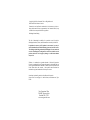
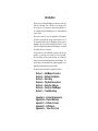
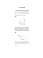
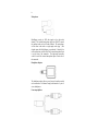
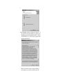
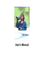
User’s Manual
Copyright @ 2005 New Generation Video. All Rights Reserved.
Printed in the United States of America.
Characteristics and specifications mentioned in this document are subject to
change without notice and are not guaranteed by New Generation Video, except
as noted in the warranty and the License Agreement.
ShotMapper Patent Pending.
The risk of determining the suitability for a particular use and of using the
ShotMapper hardware, software, and documentation rests entirely with the user.
In particular, the accuracy of GPS positions is not warranted. Accuracy is
entirely determined by the Global Positioning System and your GPS receiver.
The encoding and decoding performed by ShotMapper is not warranted to be
error free. ShotMapper is not designed to be used in cases in which errors in
position could cause a risk of property damage or could threaten human
safety or life.
Windows is a trademark or registered trademark of Microsoft Corporation.
Firewire is a trademark of Apple Computer Incorporated. Adobe and Reader are
either registered trademarks or trademarks of Adobe Systems Incorporated in the
United States and/or other countries. Other product names mentioned are
trademarks or registered trademarks of their respective owners.
Screenshot(s) reprinted by permission from Microsoft Corporation.
Maps on front cover and page 2 © 2004 DeLorme (www.delorme.com) Topo
USA®.
New Generation Video
2100 SW Wynwood Ave
Portland, OR 97225
www.newgenvideo.com
i
Introduction
Thank you for purchasing ShotMapper, an innovative video tool
from New Generation Video. Whether you are shooting video
for personal use or for scientific or commercial applications, we
are confident you will find ShotMapper to be a valuable addition
to your toolbox.
Please take a minute to review the organization of this manual,
given below, to determine the sections of most interest to you. If
you are already familiar with how ShotMapper operates, you can
immediately proceed to software installation in Section 2. If you
would like background information on ShotMapper, you should
first read the Overview in Section 1.
If your product was not automatically registered when you purchased it, we encourage you to register it as soon as possible.
This will validate your new product warranty, and will allow us
learn more about the intended applications for ShotMapper. We
can also keep you informed about any product upgrades or complementary products that may become available .
The main portion of this manual is organized as follows:
Section 1 — ShotMapper Overview
Section 2 — Software Installation
Section 3 — Recording
Section 4 — Playback Connections
Section 5 — Using the Software
Section 6 — Caring for ShotMapper
Section 7 — Troubleshooting
Appendix A — System Requirements
Appendix B — Product Warranty
Appendix C — Software License
Appendix D — GPS Basics
Appendix E — Video Time Code
ii
iii
Package Contents
The ShotMapper package includes the items listed below. You
can use the illustrations to associate the ShotMapper hardware
components with the names by which they are identified in the
manual. Please verify that your package is complete. Contact
New Generation Video if any items are missing.
SM-01:
SM-01 is the GPS-to-audio converter. The input connects to the
DB-9 connector on the GPS receiver’s data cable. The line-level
audio output can feed a LINE audio input directly. For use with
an external microphone input, the output is connected to SM-02.
SM-02:
SM-02 converts the line-level signal into a microphone level
signal for use with the camcorder’s external microphone input. It
includes a jack for connecting a microphone to record singlechannel audio.
iv
Microphone:
ShotMapper records its GPS data signal on the right audio
channel. The included microphone plugs into SM-02 to record
the ambient audio on the left audio channel. The microphone
will be either in line with or at right angles to the plug. (This
depends upon which ShotMapper you purchased.) Normally, the
in-line connection would be used if the external microphone input
is on the front of the camcorder. The right-angle connection
would be used if the external microphone input is on the side of
the camcorder.
Headphone Adapter:
The headphone adapter allows you to listen to the audio recorded
on the camcorder’s left channel using both channels of a pair of
stereo headphones.
Line-output Splitter:
v
Similarly, when using the Line audio outputs, the line output
splitter allows you to send the left-channel audio to both inputs of
a stereo amplifier.
Plug - plug Adapter:
The plug-plug adapter is used with the line-output splitter when
the line outs on the camcorder are female RCA connectors.
Software (CD-ROM): The CD-ROM contains the ShotMapper
software that reads the GPS data signal, using a Firewire
interface, recreates the original GPS data, and sends that data to
your mapping software for display. The CD-ROM also contains
an electronic copy of the User’s Manual and Acrobat Reader,
which is necessary to read the electronic manual.
User’s Manual: The User’s Manual (this document) contains the
information necessary to understand ShotMapper and to use it for
both recording and playback.
vi
vii
Table of Contents
Introduction .............................................................i
Package Contents................................................iii
Table of Contents................................................vii
Section 1 — ShotMapper Overview..................1
Basic Principles...............................................1
Section 2 — Software Installation ...................3
Installation Steps ............................................3
Adobe Reader Installation ............................7
Section 3 — Recording........................................9
Required Equipment ......................................9
ShotMapper Interface.....................................9
Connecting the GPS Receiver to
SM-01..........................................................10
Using the External Microphone Input......10
Using the Audio Line Inputs ......................10
Configuring the GPS Receiver ..................11
Configuring the Camcorder........................11
Testing the Connections.............................12
Shooting Video with ShotMapper.............13
GPS Considerations.....................................13
Section 4 — Playback Connections...............15
Preparation .....................................................15
Connecting the Camcorder to the PC......15
Connecting the Video to a Monitor ..........16
Connecting the Audio ..................................17
Listening to Audio Using Headphones...18
viii
Section 5 — Using the Software .....................19
Required Mapping Software.......................19
Starting the Software ...................................20
Connecting to the Mapping Software ......21
Setting the Port in the ShotMapper
Software....................................................22
Completing the Connection .......................23
Using the Camcorder Controller ...............24
The ShotMapper Tray Icon .........................25
The Pop-up Menu..........................................26
The ShotMapper Options Dialog...............26
Viewing the Shooting Locations...............28
Closing the Software....................................28
Section 6 — Caring for ShotMapper ..............29
Section 7 — Troubleshooting ..........................31
Recording Questions/Problems................31
Playback Questions/Problems ..................33
Appendix A — System Requirements ...........37
Camcorder Requirements...........................37
GPS Receiver Requirements......................37
Computer System Requirements..............38
Mapping Software Requirements .............38
Appendix B — Product Warranty....................41
Appendix C — Software License
Agreement.......................................................43
Appendix D — GPS Basics...............................49
GPS Positioning ............................................49
ix
GPS Limitations ............................................ 49
Appendix E — Video Time Code .................... 51
Drop-frame Time Code................................ 51
DV Time Code................................................ 52
x
1
Section 1
ShotMapper Overview
Have you ever returned from a week of shooting video
only to wonder: “Where was that shot?” Perhaps you
were backpacking in a wilderness area and you shot an
unusual flowering plant “in the middle of nowhere.”
Perhaps you captured a close-up of a marine mammal
while sailing in the San Juan Islands. Or perhaps you
needed to know exactly where some historic artifacts
were found.
With ShotMapper, you no longer have to wonder, remember, or log exactly where these scenes occurred.
Provided you have a DV camcorder* with a microphone
input and an IEEE 1394 (“Firewire”) interface, you can
use ShotMapper to record the location from your GPS
receiver and, when playing back the tape, to see the
location on a map.
ShotMapper supports a myriad of applications, both for the amateur and for the professional. The following list is only a brief
indication of the possible uses for ShotMapper.
•
•
•
•
•
•
•
•
Aerial videography
Archeology
Law enforcement
Location scouting (moviemaking)
Marine science
Systematic botany and forestry
Tourism and Travel logs
Wildlife biology
Basic Principles
You supply the GPS (Global Positioning System) receiver and
the DV camcorder. The ShotMapper hardware connects between
the two to continuously record GPS position data on the right
audio channel of the tape.
2
After the DV tape has been recorded, the ShotMapper software
can be used to display the shooting location on your PC/monitor
using third-party mapping software.
Markers show track taken when
video was shot. This is illustrative
only. Map display, and display of
location on map, depends completely on the third-party mapping
software used.
The ShotMapper software works with virtually any Windowscompatible PC equipped with an IEEE-1394, or “Firewire,” interface. (See Appendix A for complete requirements.) Simply connected your digital camcorder to your PC using an IEEE 1394
cable. During playback, the ShotMapper software allows you to
remotely control the camcorder using a controller panel displayed
on your PC monitor screen.
3
Section 2
Software Installation
As noted in Section 1, the ShotMapper software is used only
when playing back videos that were recorded with GPS data.
You may connect the ShotMapper hardware to your GPS receiver
and camcorder, as described in Section 3, and begin to record
videos with location data before installing the software.
To install and use the ShotMapper software, you should be familiar with basic Windows operations and commands. If you are not
an experienced Windows user, it may be helpful to review your
Windows and computer manuals before proceeding.
ShotMapper requires Windows 98, Windows ME, Windows
2000 or Windows XP (Home or Professional) in order to function properly. For a complete list of computer and other requirements, refer to Appendix A. If your equipment does not meet
these requirements, do not install the software and return the
ShotMapper package to New Generation Video for a full refund
(less shipping and handling).
Installation Procedure
1)
Exit all Windows applications before beginning the installation of the ShotMapper software.
2)
Insert the ShotMapper CD into the CD-ROM drive of your
computer.
3)
If the installation wizard does not appear after you insert the
CD, do one of the following:
a)
Click the Start icon at the lower left of your monitor.
Click on Run from the pop-up menu.
In the Run window, enter the command “D:\setup,”
where “D” is the drive letter of your CD-ROM drive. If
your CD-ROM drive has another letter, use that drive
letter.
Select OK.
4
b) Right-click on the file “Setup.exe” in the CD-ROM
folder and choose “Open” from the pop-up menu.
c)
Double-click on the file “Setup.exe” in the CD-ROM
folder.
4)
An introductory screen appears and gives you several
choices. Choose “Install Products.”
5)
Choose “Install ShotMapper” from the next Screen.
6)
An Install Shield wizard will to guide you through the installation process. To proceed with the normal installation
steps, click on the “Next” or “Install” button at each step,
after reading the information on each screen and making any
required choices. To cancel the installation at any time —
without installing the software — click on the “Cancel” button.
Note: Depending upon your operating system and the
version of ShotMapper software that you are installing,
the screens of the installation wizard may appear slightly
different than shown.
7)
In order to install the software, you must accept the New
Generation Video license agreement:
5
8)
If you wish, you may change the default folder in which the
application is installed.
9)
You may choose either to install or to not install an electronic copy of this User’s Manual along with the software.
6
10) The ShotMapper software uses Microsoft’s DirectX 9. If
this software is not already installed on your computer, the
installation procedure will automatically install it. In order
to install DirectX 9, you must accept a separate license
agreement from Microsoft.
Note: If the DirectX software is already installed on
your computer, you may still be asked to accept this
7
license agreement. However, the software will not be
again copied to your computer.
11) At the end of the installation procedure, you may need to
complete the installation by restarting your computer. The
installer will offer to do the restart immediately
Normally, you should allow the install procedure to restart
the computer. If you have other applications running, or for
some other reason you do not want the computer to restart,
you can choose to restart it yourself at a later time. You
must restart the computer before you can use the ShotMapper software.
Adobe® Reader® Installation
If you chose to install the electronic version of the ShotMapper
manual on your hard drive, you must have Adobe Acrobat or
Adobe Reader installed in order to view it. If you do not, you
may install Adobe Reader by following steps 1) to 4) in the previous section. From the “Install Products” screen, choose “Install
Adobe® Reader®” and follow the instructions of the install
wizard.
8
9
Section 3
Recording
Creating videos that include GPS location data is simple. If you
have experience in videomaking, you should encounter no difficulty in using the ShotMapper system. This section describes
how to connect your GPS receiver, ShotMapper, and your camcorder; how to record videotapes; and considerations to be aware
of when shooting while using GPS.
Required Equipment
For recording, you will need the ShotMapper interface, a GPS
receiver, and a digital camcorder. See Appendix A for a list of
requirements that the GPS receiver and the camcorder must meet.
ShotMapper Interface
The ShotMapper recording interface consists of three components: the SM-01 converter; the SM-02 microphone adapter cable; and a microphone.
SM-01 is a GPS-to-audio converter; it contains a male DB9 connector for GPS data input and an RCA phono jack for audio output. The converter converts the GPS data into an audio line-level
signal (approximately 500 mV).
SM-02 is an interface that attaches to the SM-01 converter, via a
cable terminated in an RCA phono plug, and attenuates the linelevel signal to a level (approximately 5 mV) suitable for connection to the camcorder’s external microphone input. The assembly
at the camcorder end of the cable contains a stereo mini-plug for
connection to the camcorder and a monaural mini-jack for connection of an external microphone. The connected microphone
records ambient audio on the left audio channel of the camcorder.
In the most common connection — using the external microphone input — you will use SM-01, SM-02, and the microphone.
However, if you use a line level input, you will need only SM-01.
10
Connecting the GPS Receiver to SM-01
1)
Connect the GPS receiver to its matching data output cable.
2)
Connect the other end of the GPS data output cable (a female
DB9 connector) to the male DB9 connector on SM-01.
Note: A few newer GPS receivers are supplied
with a USB (Universal Serial Bus) connector and
cable rather than an RS-232 DB9 connector and
cable. Such receivers require a USB to RS-232
converter. The converter must be powered either by
the GPS receiver or by an external power source.
No power is available from SM-01.
Using the External Microphone Input
1)
Connect the RCA phono plug at the end of the SM-02 cable
to the RCA phono jack of SM -01.
2)
Plug the SM-02 mini-plug into the external microphone input
of the camcorder.
3)
Plug the microphone into the SM-02 mini-jack.
You may also use your own microphone with SM-02. (For
example, you might want to use a microphone with a cable
so that the microphone can be located farther away from the
camcorder.) The Microphone jack on SM-02 is a monaural
(mono) mini-jack but, depending upon how it is wired, a
microphone with a stereo mini-plug will probably work also.
(The microphone included with ShotMapper has a stereo
mini-plug.) Some microphones with a stereo mini-plug use
only a single microphone connected to both channels. If a
true stereo microphone is used, only the left-channel microphone will be recorded.
Using the Audio Line Inputs
In most situations, you will use the external microphone input, as
described above. The most common situations in which you
would use the line inputs are:
11
•
You are using a camera connected to a digital deck instead of
a camcorder. In this case, the camera would be connected to
the deck’s video input and audio to its audio line inputs.
•
Your camcorder allows selecting the audio line inputs instead
of the external microphone input when recording as a camcorder (“through the lens”). This is not common.
To use the audio line inputs, connect a standard audio cable, having an RCA phono plug on each end, between SM-01 and the
right line input. The left line input may be used to record a linelevel audio signal.
Configuring the GPS Receiver
The method of configuring the GPS receiver will depend upon the
model you have. Configuration information may be found in the
instruction manual of your GPS receiver.
Some GPS receivers can put out data in either NMEA format or
in a proprietary data format. Using the appropriate menus on
your GPS receiver, select the NMEA format.
The NMEA standard specifies a baud rate of 4800 baud. However, some GPS receivers will output NMEA format data at different baud rates. If your receiver allows you to chose the baud
rate, select 4800 baud.
Configuring the Camcorder
Most camcorders will require no configuration. If you have a
camcorder that allows use of line inputs instead of the external
microphone input (when operating as a camcorder), you may
need to enable those inputs through a menu. You may want to
select between manual and automatic gain control. When using
manual gain control, you may need to discover the optimum setting through experimentation.
Consult the instruction manual of your particular camcorder to
see how these steps are performed.
12
Testing the Connections
Since ShotMapper produces an audio signal, you can verify that
the components are connected and configured correctly by using
a pair of headphones (assuming your camera has a headphone
output). To test the setup:
1)
Connect the GPS receiver, ShotMapper, and the camcorder
as described above, according as you are using the external
microphone inputs or the audio line inputs.
2)
Plug a set of headphones into the camcorder. Do not use the
headphone adapter described in Section 4.
3)
Verify that the GPS receiver is configured for NMEA output
and that the camcorder is configured, if necessary. For more
information, see the earlier portion of this section and the
manuals for the GPS receivers and the camcorder.
4)
Turn on the GPS receiver and the camcorder. The camcorder should be in “Camera” mode, not “VCR” mode. With
most camcorders, you will be able to hear the audio without
actually recording on a tape. Consult your camcorder manual
or experiment to determine whether or not you do have to be
recording to monitor the audio.
5)
Listen to the audio in the headphones. You should hear the
ambient audio in the left headphone and a buzzing sound in
the right headphone. Depending upon your GPS receiver,
the buzzing may be continuous or may be present only part
of the time. (For example, the buzzing, which represents the
GPS data output, may alternate between being present for 1
second and absent for 1 second.)
Caution: The buzzing may be louder than the than the
normal audio from the camcorder. You can protect your
ears by holding the headphone, especially the right headphone, near, rather than on or in your ears.
If the audio in the headphones is not as described, see Section 7
for troubleshooting hints.
13
Shooting Video with ShotMapper
While using ShotMapper, you shoot your video much as you did
before. There are a few things which are or may be different, as
well as some things you must do to ensure valid data from the
GPS receiver.
The biggest difference is that you will have only monaural audio.
The difference should not be noticeable for narration, but ambient audio will not have a stereo effect. (See Section 4 for playback audio connections.)
Make sure that each video clip is long enough to capture a complete position from the GPS receiver. GPS receivers typically
repeat location information every one or two seconds. The minimum clip duration should be three to four seconds. Your receiver may be different; consult the receiver’s instruction manual
or experiment to find the minimum clip duration required.
Also, if you will want to depict the track or direction of travel
during playback, the video clip must have a sufficient duration
that the mapping software can detect a change of position. The
required duration depends upon the speed of movement (e.g.,
walking vs. traveling in a vehicle), the scale selected in the mapping software, and the rate at which the mapping software updates the position. In some mapping software, an arrow indicates
the track, while with other software, the track must be determined
from the movement of the position indicator over the map.
GPS Considerations
ShotMapper will record location data anywhere GPS satellite
signals are available: virtually anywhere in the world, whether on
land or sea or in the air. Signals from the GPS satellites travel in
straight lines. Thus, the GPS receiver must have a clear “view”
of the sky so that it can receive signals from at least three satellites. Because the positions of the satellites in the sky are constantly changing, what is a good view at one time may become a
poor view a few minutes later. Outdoors, the signals may be
blocked by heavy trees or, in cities, by tall buildings. Indoors or
in a vehicle, the receiver, or at least the antenna, will usually need
14
to be near a window.
To give yourself more freedom while shooting, you may want to
attach the receiver to your backpack or in some other location
where it is facing up (as it would be if held in your hand). If
necessary, you may use a male -female RCA cable, or cable and
adapter, between SM-01 and SM-02 so that you may locate the
GPS receiver farther from the camcorder.
Before beginning to record a clip, especially in a new location,
make sure that the GPS receiver has completed its power-on
initialization process and has acquired the satellites. (The GPS
receiver will usually indicate whether it has or has not acquired
the satellites. It may display a message like “Ready to navigate”
or an estimated position error (EPE) when it has acquired the
satellites. Alternatively, it may blank the position display when it
has not.) Please refer to the GPS receiver instruction manual for
more information.
The GPS receiver may lose the satellite signals if the antenna
(which may be internal to the receiver and not visible) is not facing the sky. Thus, after moving to a new shooting location, you
may need to again position the receiver and wait for it to acquire
the satellites. This is true even if the receiver has been powered
on while moving. The time required to acquire the satellites varies among GPS receivers.
For more information about general concepts of GPS operation
and terminology, consult Appendix E. Basic information about
the features and use of GPS is also available at the New Generation Video website: www.newgenvideo.com
15
Section 4
Playback Connections
After you have recorded video that includes GPS location data,
you can display the shooting locations using a PC equipped with
the ShotMapper software. This section describes how to set up
your playback system with your computer.
Preparation
The instructions in this section and in Section 5 assume that your
basic PC system has been configured properly, with the monitor,
keyboard, printer, etc. having been connected and any required
drivers installed. It is also assumed that your PC has an IEEE
1394 interface card installed and that any necessary driver is
installed and configured. For convenience, we will hereafter
refer to IEEE 1394 by the more commonly known term,
“Firewire.”
Connecting the Camcorder to the PC
Your camcorder must be connected to your PC using a Firewire
cable. Be sure you have the correct cable for your camcorder and
computer. There are two standard Firewire connectors: a large
rectangular 6-pin connector and a smaller rectangular 4-pin
connector. Camcorders use the small connector. Most desktop
PC’s use the large connector; some laptops use the small
connector.
Plug a matching cable end into each connector (on the camcorder
and on the computer). Firewire devices are “hot-pluggable”; that
is, they may be connected and disconnected while the computer is
running.
Camcorders generally include a mode switch to select between
recording through the lens and playback (and sometimes
recording) as a VCR. Often, there is a power/mode switch with
three positions: “Off,” “VCR,” and “Camera.” Consult the
camcorder manual for specific information on your particular
16
model. When playing back video with ShotMapper, set the mode
switch to “VCR” (or the equivalent function on your camcorder).
Connecting the Video to a Monitor
Though not absolutely required, it is helpful to connect an
external monitor to your camcorder to give a bigger video display
during playback. This may be a dedicated, video-only monitor,
or a TV set or home theater system with an external video input.
You may also connect to a TV set using an RF modulator
connected to the camcorder, or connect through a VCR with an
external video input. The monitor may include built-in speakers
that will allow you to hear the audio recorded on the left channel.
The standard input and output connections for video and audio
use RCA phono jacks (or plugs). The standard color coding for
the connectors is: yellow for video, red for the right audio
channel, and white (or, on audio equipment, sometimes black) for
the left audio channel. This coding should be the same,
regardless of whether you are connecting to the external inputs of
a TV receiver, a VCR, a home theater system, or to a stand-alone
RF modulator.
Dedicated monitors with only a video input may not follow these
conventions and may use BNC, rather than RCA, connectors.
There are other considerations when using a professional video
monitor with “loop-through” inputs. See the monitor manual for
details.
The camcorder may have a single “A/V” connector rather than
individual audio and video connectors. A breakout cable, usually
supplied with the camcorder, plugs into the A/V connector and
supplies, at its other end, three RCA jacks or plugs, color-coded
as given above.
To make a standard video connection, use a video-quality cable
with an RCA phono plug on each end, connecting one end to the
video output jack on the camcorder or the breakout cable and the
other end to the video input jack. If you have a breakout cable
that ends in RCA phono plugs, the video output may be plugged
directly into the video input.
17
If both the camcorder and the monitor (or VCR, etc.) have Svideo connectors, you will probably want to connect these with
an S-video cable instead of using the standard video connection
(known as composite video) described above. S-video gives a
higher quality picture than does composite video.
Some camcorders may have an associated RF modulator that
connects directly to the camcorder through a single cable. You
should avoid this setup if possible, since you will not be able to
make the proper audio connections (as discussed next) to listen to
the recorded audio while blocking the GPS signal.
If you are using a monitor, VCR, or home theater system with
more than one input, make sure to select the input to which the
camcorder is connected.
If you are using an RF modulator, make sure that that the TV set
is tuned to the same channel (3 or 4) as is the modulator.
Connecting the Audio
To listen to the single-channel audio recorded by ShotMapper,
while ignoring the encoded GPS signal, use the provided RCA
phono plug Y-splitter. Connect the “jack” end of the splitter to
the left audio output (white) connector on your camcorder or
breakout cable. If the connectors on the end of a breakout cable
are RCA phono plugs, the left plug will plug directly into the
splitter. If the connector, on either the camcorder or a breakout
cable is a jack, use the supplied plug-plug adapter or a cable with
phono plugs on the ends (not supplied) to connect to the splitter.
Connect the free ends of the splitter to both the left and right
audio inputs (color coded and/or marked with “L” and “R”) on
the monitor or other device. If the monitor has a single audio
channel, simply connect it to the left output of the camcorder
without using the splitter.
Note: Camcorders are often connected using a cable
assembly which has one video and two audio cables
joined together. This is exactly equivalent to the
individual cables described. Use the video cable to
connect to the monitor or other display. Use one of the
18
audio cables to connect the camcorder to the splitter.
Note: If you recorded using the audio line inputs, and
accidentally reversed the inputs, simply use the right
(red) audio output instead of the left audio output. In
this case, you will also need to note the information on
configuring the ShotMapper software to work with
reversed channels. This information is given in Section
5.
Listening to Audio Using Headphones
Rather than listening to the audio through your monitor or an
audio amplifier and speakers, you may want to listen via a pair of
headphones. The ShotMapper package includes a stereo miniplug adapter, which allows you to listen to the single channel of
recorded audio on both channels of your stereo headphones.
Plug the splitter into the camcorder’s headphone jack. The
splitter has two jacks: the silver jack carries the left channel
signal, the gold jack carries the right channel signal. To listen to
the recorded audio, plug your headphones into the silver jack.
Note: If you recorded using the audio line inputs, and
accidentally reversed the inputs, simply plug the
headphones into the gold jack. In this case, you will also
need to note the information on configuring the
ShotMapper software to work with reversed channels.
This information is given in Section 5.
19
Section 5
Using the Software
This section describes how the ShotMapper software works with
your third-party mapping software to display the shooting
locations, how to use the ShotMapper software to remotely
control your camcorder, and the controls and options associated
with the ShotMapper software’s windows and menus.
The ShotMapper software uses the data transferred to the
computer over the Firewire interface to recreate the GPS
positions at which the video was shot. The positions are sent to
your third-party mapping software, which displays them in the
same manner as it would have if the GPS receiver had been
connected to a computer running the mapping software at the
shooting location. Depending upon the capabilities of the
mapping software, it may also display track (if moving), heading,
speed, altitude, and/or other data, in addition to position.
Since the focus during playback is on the information provided
through the mapping software, the ShotMapper software is
designed to interfere as little as possible with the display of that
information. You may set the ShotMapper software so that
during normal operation (when it is not being configured), the
only indication of its presence is a small icon in the “tray” area of
the Windows taskbar. With this minimal interface, you control
the camcorder normally, as you would if it were not connected to
the computer. Alternately, you may use a Camcorder Controller
window to control the camcorder via the mouse.
Required Mapping Software
ShotMapper software works with third-party mapping software.
In order to display shooting locations with ShotMapper, you must
have mapping software intended to work with a generic, NMEA compatible, GPS receiver connected to a serial (COM) port.
Typical examples of mapping software include Microsoft “Streets
and Trips,” Rand-McNally “Street Finder” and the various
DeLorme products. (These titles are listed for reference only and
20
are not endorsed or warranted to meet your needs. Also,
endorsement of ShotMapper by the manufacturers of these
products is not implied. You have the responsibility of selecting
mapping software that will provide the functions that you need.)
By now, you should have installed the ShotMapper software and
the mapping software. If you have not installed the ShotMapper
software, do so now, using the instructions provided in Section 2.
Install the mapping software, if necessary, using the instructions
that came with that software.
Starting the Software
You should start the ShotMapper software before you start the
mapping software. You can do this in a number of ways, such
as:
•
clicking on a desktop icon for ShotMapper
•
opening the Start Menu and selecting “Programs/New
Generation Video/ShotMapper”
•
double-clicking ShotMapper in Windows Explorer
•
right-clicking ShotMapper in Windows Explorer and
selecting “Open” from the pop-up menu
As the ShotMapper software starts up, it displays a splash screen
showing the ShotMapper software version number. If you have
selected that the Camcorder Controller always be displayed at
program start-up, the controller will appear when the splash
screen disappears. The ShotMapper software displays an icon in
the area of the Windows taskbar known as the tray (in the lower
right corner of the PC screen). Both the controller and the tray
icon are discussed later in this section.
After starting ShotMapper, start the third-party mapping software
in a similar manner.
Connecting to the Mapping Software
The ShotMapper software decodes the audio GPS data signal
from the tape and recreates the NMEA data stream originally
21
produced by the GPS receiver. The data is made available
through a virtual serial communications port. This port does not
physically exist, but the ShotMapper software creates the same
interface as a physical port would have. Thus, the port and its
data appear to the operating system and to other applications in particular, to the mapping software - as would a hardware
serial communications port (e.g., ‘COM1’) with data coming
from a GPS receiver connected to the port.
You will have to select the COM port name to be used for the
virtual GPS receiver. The same port must be selected in the
ShotMapper software and in the mapping software.
You need to set the virtual GPS port in the ShotMapper software
before selecting it in the mapping software. However, you need
to look at how you select the port in the mapping software in
order to chose the port in the ShotMapper software.
Consult the instructions for the mapping software to determine
the menus used to configure a GPS receiver. The menu selection
for choosing the GPS port will probably have, as part of its
name, a word such as Configure or Settings:
The ports that are available for GPS use may be shown in either
of two ways. The first is through a port list:
When using a port list, the mapping software obtains the
available ports from the operating system. The virtual port may
be set up (in the ShotMapper software) to use any port name that
22
does not conflict with a port physically present on the computer.
Alternatively, there may be a fixed set of possible ports:
The virtual port must use a name that is in the given set but does
not conflict with a port physically present on the computer.
Setting the Port in the ShotMapper Software
Right-click on the ShotMapper tray icon. Select Options…
from the pop-up menu that appears. This will display the
ShotMapper Options dialog.
Clicking on the arrow to the right of the port name listing will
drop a list of available port names.
23
The port name chosen must not conflict with a hardware
communications port physically present on the computer. Most
desktop computers have two ports, COM1 and COM2. Some
desktops and some laptops have COM1 only. Many recent
laptops do not have any serial ports. Many internal modems are
installed as COM3. A USB-to-serial adapter may be installed as
COM4.
The default name, COM4, should be acceptable in most
situations, unless you have added serial ports to your computer or
you are using a USB-to-serial cable. If you must change the
name, any other name is acceptable provided that your mapping
software builds a list of the available ports. If the mapping
software gives you only predefined choices, you must choose a
name which is an available choice. If you cannot find an
acceptable name, see the item “I have a port naming conflict”
under “Playback Questions/Problems” in Section 7.
Choose the desired port name from the drop-down list. The
name, along with all other ShotMapper options, is remembered
and is restored whenever you start the ShotMapper software.
Completing the Connection
After you have selected a port name in the ShotMapper software,
select the same port in your mapping software. You may get an
error in the mapping software if you select the port before the
ShotMapper software creates it.
24
If the mapping software requires you to select a GPS data format,
select “NMEA” or, if it is available “NMEA 2.0.” The NMEA
standard specifies 4800 baud. However, your mapping software
may allow you to select the baud rate. The port created by the
ShotMapper software will adapt to the baud rate you set. To
avoid losing data, you should select 4800 baud or greater.
Your mapping software may require you to start GPS tracking in
order for it to display the positions provided by the ShotMapper
software.
Using the Camcorder Controller
By default, the ShotMapper software displays the Camcorder
Controller when it starts. The Controller displays the time code
read from the tape and provides buttons to control basic
camcorder functions.
The time code is displayed as “hours:minutes:seconds:frames.”
For more information on time code, see Appendix E.
The buttons control tape movement in the camcorder remotely,
using the mouse, over the Firewire interface. The buttons serve
the same functions as controls on the camcorder.
Rewind
Stop
Pause Play
Fast Forward
25
When a button is selected, it appears depressed and the icon in
the button becomes red. The buttons show the actual mode of the
camcorder, even if the mode is set using the controls on the
camcorder rather than the Camcorder Controller.
Clearing the “Show at Startup” checkbox will prevent the
Camcorder Controller from being automatically displayed when
the ShotMapper software starts.
Clicking the “Done” button removes the Camcorder Controller
from the screen. This does not exit the ShotMapper software.
The controller may again be displayed by choosing “Show
Controller” from the pop-up menu that appears when you left click on the ShotMapper icon.
The ShotMapper Tray Icon
When the ShotMapper software is running, it displays the icon of
a miniature GPS receiver in the tray area of the taskbar. When
the Camcorder Controller, the pop-up menu, and the options
dialog box are not displayed, this icon is the only indication that
the ShotMapper software is running.
The color of the
representation of the display screen in the icon gives information
on the GPS data being read from the tape.
Red indicates that the Firewire interface does not detect a
DV camcorder (or deck).
Gray indicates that the camcorder is stopped: the tape is
not playing.
Blue indicates that the tape is playing, but no GPS data is
present on the tape.
Yellow indicates that GPS data is present on the tape, but
the GPS receiver had not acquired enough satellites to
find a valid position.
Green indicates that valid GPS positions are being read
from the tape.
Resting the mouse pointer over the icon will display a text string
indicating the current status.
26
The Pop-up Menu
Left-clicking on the ShotMapper icon brings up a pop-up menu:
To select a menu item, left-click on it.
Show Controller – This selection displays the Camcorder
Controller (if it is not displayed) or hides it (if it is currently
displayed). The item is checked if the controller is displayed.
Options... – This selection is discussed later in this section.
About... – This selection redisplays the information that was
shown in the splash screen as the ShotMapper software started.
Exit – This selection exits the ShotMapper software. See the
information on closing the program later in this section.
The ShotMapper Options Dialog
The Options... menu item brings up a dialog box:
27
“Controller always on top,” when checked, displays
the Camcorder Controller on top of every other window (except
for the ShotMapper Options dialog box), even when the controller
window is not active. When this option is not selected, the
Camcorder Controller may be hidden by other windows when it is
not the active window.
Keeping the Camcorder Controller on top of other windows
allows you to easily control the camcorder while viewing the
mapping software. The controller may be moved to a convenient
part of the screen by dragging it by the title bar. (Place the mouse
over the title bar, press the left mouse button, move the window
where desired, release the mouse button.)
“Invert audio channels,” when checked, interchanges
the audio channels. The GPS data signal is then taken from the
left channel instead of from the right channel. Check this only if
the channels were swapped when recording, as will happen if the
cables are interchanged when using the audio line inputs.
“Output Port” selects the name to be used for the virtual
communications port that sends data from the ShotMapper
software to the mapping software. Considerations involved in
choosing a port name were discussed earlier in this section.
“Check Map Interface,” when clicked, sends a fixed
position to the mapping software. This verifies that the
ShotMapper software is properly communicating with the
mapping software.
The recessed box below the controls displays a help message for
each control as the mouse is passed over the control.
Selecting “OK” closes the dialog box and changes ShotMapper’s
settings to match the values entered. Selecting “Cancel” closes
the dialog box, but ignores any settings changes made.
Viewing the Shooting Locations
When the mapping software is receiving data from the
ShotMapper software, the displayed map corresponds to the
general area where you were shooting the video. An indicator
28
will be displayed on screen at the exact location given by the
GPS receiver when the video was shot. You may change the
scale of the map to enlarge or shrink the area displayed around
the shooting location. (Consult the manual for your mapping
software to determine how to change the map scale and how to
set up the display in other ways to meet your needs. Any
configuration or feature described in connection with operating
with a GPS receiver applies when operating with ShotMapper.)
The ShotMapper software updates the position sent to the
mapping software as the tape is played. If you were moving
while shooting a particular video scene, the position indicator on
the map will move as the scene plays. If there is a large change
in location between scenes, the map and position indicator will
jump to the new location when the new scene starts. Because of
the way the mapping software operates, the map may not update
to the new location for several seconds after the scene change.
Closing the Software
When you are finished using ShotMapper, it is best to exit the
mapping software or disconnect it from the virtual port (usually
by stopping GPS tracking) before you exit the ShotMapper
software. This will allow the ShotMapper software to completely
delete the virtual port before it exits.
Exit the ShotMapper software by choosing “Close” from the popup menu that appears when you left-click on the ShotMapper
icon. If the ShotMapper software is still connected to the
mapping software, you will see a message box asking if you
really want to exit. Select “No” if you first want to exit or
disconnect the mapping software. Select “Yes” to cause
ShotMapper to exit immediately
29
Section 6
Caring for ShotMapper
Most components of ShotMapper are reasonably rugged.
However, you should treat them with the same care as you would
any other electronic components or equipment: for instance, your
GPS receiver or camcorder.
Use care when connecting the different components together.
Make the connections securely, but don’t force them. Check the
connections frequently while recording to make sure that they
have not been loosened by normal shooting movement.
Especially when shooting outdoors, take care when making the
connections that dirt or other foreign matter does not get into the
connectors.
The assembly at the end of SM-02 that plugs into the camcorder
is somewhat large, especially with the microphone connected.
Do not hit or bump it so as to put force on the camcorder’s
external microphone connector.
When recording outdoors, always leave the windscreen on the
microphone for protection and reduced wind noise. When
recording indoors, you may remove the windscreen. Always
install the windscreen for protection when the microphone is not
being used.
You may clean the exterior of the microphone body with a soft
cloth moistened with clean water, drying it with another cloth.
Do not wet the microphone element (under the windscreen).
Rather, carefully brush away any dirt with a Q-tip, being careful
not to lift the covering over the element.
30
31
Section 7
Troubleshooting
This section describes questions and problems that you may face
when using ShotMapper. It gives additional information and for problems - their causes, preventative actions and, where
possible, recovery methods. If these scenarios do not describe
your situation, see the support pages at www.newgenvideo.com.
Problems that occur while recording video may not be detected
until playback. Problems are listed below according to where
hey are detected.
Recording Questions/Problems
“How can I be sure that everything is connected and
configured properly and that a signal is being recorded?”
The GPS data is recorded as an audio signal. Therefore, it can be
heard on headphones. To determine if GPS data is being
recorded, plug a set of stereo headphones into the camcorder. Do
not use the headphone adapter (described in Section 4). The left
headphone should output the audio from the ShotMapper
microphone, while the right channel outputs the GPS data. The
GPS data will be heard as a buzzing sound. Depending upon
your GPS receiver, the buzz may be continuous or there may be a
regular pattern, such as one second of data followed by one
second of silence.
Caution: The buzzing may be louder than the than the
normal audio from the camcorder. You can protect your
ears by placing the headphones near, rather than on or in
your ears.
“During the connection test, I hear the microphone audio, but
do not hear the GPS data signal.”
If you do not hear the GPS data properly, make sure that all
connectors are plugged tightly together and that the GPS receiver
is properly configured for NMEA output (see Section 4).
32
If your camcorder has analog video inputs, you can check to see
whether SM -01 is putting out an audio signal. Connect the
output of SM-01 to one of the audio LINE inputs, using a cable
with an RCA phono plug on each end. (For this test, it does not
matter whether you use the left input or the right input.) Make a
short test recording. Connect headphones to the camcorder
(without using the headphone adapter). Either monitor the audio
during recording or listen during playback. You should hear the
GPS data signal on the channel to which it is connected.
Caution: The buzzing may be louder than the than the
normal audio from the camcorder. You can protect your
ears by placing the headphones near, rather than on or in
your ears.
If you can hear the signal from SM -01, but not when the external
microphone input is used with SM -02, the cable in the SM-02
assembly is probably defective.
“During the connection test, I hear the GPS data signal, but
do not hear the microphone audio.”
The microphone included with ShotMapper requires a small
voltage from the camcorder. This is known as “plug-in power.”
Note: Plug-in power is not the same as “phantom
power,” used in professional audio equipment.
If your camcorder does not provide plug-in power, the included
microphone will not record a signal. You may substitute a
microphone of a type that does not require power, or one for
which the voltage is supplied by a battery.
“During the connection test, I hear the microphone audio on
the right channel instead of the left, and do not hear the GPS
data signal.”
This probably means that the SM-02 assembly is not plugged
completely into the external microphone input.
33
“During the connection test, the audio signals are reversed:
the GPS data signal is on the left channel and the microphone
audio is on the right channel.”
If your are using the LINE audio inputs, the connections to the
two audio inputs have been swapped. In the unlikely event that
this occurs when using the external microphone input, the
channels on the input connector have evidently been swapped.
This will have to be corrected during playback.. (See Section 4.)
Playback Questions/Problems
“The camcorder cannot be controlled from the ShotMapper
Controller.”
If the color in the ShotMapper icon is anything other than red, the
software has detected the camcorder. Check that the camera
mode is set to “VCR,” not “Camera.” If the camcorder, in VCR
mode, cannot be controlled by ShotMapper, it may have a
nonstandard control protocol. The camcorder may be controlled
through its own control buttons and/or menus. The camcorder
mode shown in the ShotMapper controller probably will not be
correct, and the time code may not be displayed properly.
So that we may continue to improve our products, we would
appreciate it if you would let us know of any camcorder that
cannot be controlled using the standard protocol. Contact New
Generation Video at the addresses or phone numbers shown in
this manual, or see “www.newgenvideo.com/Support/.”
“The ShotMapper icon shows Receiving GPS Data (yellow),
not GPS Data Valid (green).”
During recording, the GPS receiver did not acquire a sufficient
number of satellites (a minimum of three are needed) to compute
a position. Unfortunately, this cannot be fixed on playback.
The GPS receiver may not have had a clear view of the sky. For
example, it may have been indoors or under a heavy tree cover.
The receiver may have been positioned so that the antenna did
not face the sky. (If the GPS receiver has an internal antenna, the
proper position is with the controls and display facing up. A belt
34
holster, while it keeps the hands free for operating the camcorder,
generally does not place the antenna in the proper orientation.) Or
you may have started shooting too soon after the GPS receiver
was turned on or moved to a new location. The GPS receiver
must have time after turn-on, or after movement with the antenna
in the wrong orientation, to acquire the satellites. See your GPS
manual for information on how the receiver indicates that it is
producing valid positions, and ensure that it is doing so before
beginning to shoot.
“The mapping software indicates that the GPS data is ‘2-D.’”
The full GPS position includes latitude longitude, and altitude. A
‘2-D’ position is latitude and longitude only. A GPS receiver
must acquire three satellites to find a ‘2-D’ position, but must
acquire at least four satellites to find a full position. See the
previous item for a discussion of why the GPS receiver might
have a problem acquiring satellites.
“ShotMapper does not indicate that GPS data is being
received.”
Connect a pair of headphones to the camcorder, or connect a
stereo amplifier to the audio LINE outputs, without using the
adapters that came with ShotMapper. The GPS data signal
should be on the right channel and audio from the ShotMapper
microphone should be on the left channel. The GPS data will be
heard as a buzzing sound. Depending upon your GPS receiver,
the buzz may be continuous or there may be a regular pattern,
such as one second of data followed by one second of silence.
Caution: The buzzing may be louder than the than the
normal audio from the camcorder. If using headphones,
you can protect your ears by placing the headphones
near, rather than on or in your ears. If using a stereo
amplifier, keep the volume low.
If there is no GPS data signal, see the item “During the
connection test, I hear the microphone audio, but do not hear the
GPS data signal” in the “Recording Questions/Problems”
section. If the signals are reversed, that is, the GPS data signal is
on the left channel and the recorded audio is on the right channel,
see “The GPS data signal is on the wrong channel,” below. If
35
you hear the GPS data signal, see “The tape has a GPS data
signal, but the ShotMapper software is not receiving GPS data,”
below.
“The tape has a GPS data signal, but the ShotMapper
software is not receiving GPS data.”
Make sure that the ShotMapper icon is not showing the red color.
If it is, the camcorder is not connected properly to the Firewire
interface.
Make sure that the GPS receiver is set for NMEA output, not the
manufacturer’s proprietary format. This is a recording problem
that unfortunately cannot be fixed during playback.
If the baud rate of the GPS receiver is settable, make sure it is set
to 4800 baud. This is the only baud rate defined for the NMEA
protocol, but some receivers allow the baud rate to be adjusted.
This is a recording problem that unfortunately cannot be fixed
during playback.
If no explanation can be found, uninstall and reinstall the
ShotMapper software. Before doing this, check playback, if
possible, using a tape known to have played back successfully.
If the tape still plays back successfully, the software installation
is correct.
“The GPS data signal is on the wrong channel.”
Right-click on the ShotMapper icon. Select Options...from
the pop-up menu. Select the check box for Invert Audio
Channels.
For information on what can cause this problem during
recording, see the item “During the connection test, the audio
signals are reversed: the GPS data signal is on the left channel
and the microphone audio is on the right channel,” under
“Recording Questions/Problems” earlier in this section.
“After the shooting location changes, the map displays the
old location for a period of time.”
Several things can contribute to a delay in updating the map
display when a new scene changes the shooting location. The
36
GPS receiver outputs a new position only periodically,
commonly once a second. Thus, it can take up to two seconds
after a new scene starts before a new position is read from the
tape.
Some mapping software does not update every time it receives a
new GPS position, but sets its own longer update interval.
Finally, depending upon the distance that the new scene is from
the previous scene, the mapping software may have to load new
data from the hard disk (if the map data was installed on a hard
disk) or the map CD or DVD (if it wasn’t). Loading map data
from a CD or DVD is slower than loading it from the hard disk.
If the map update is unduly slow, check whether you are running
any background applications, including those that access a
network. You may have to stop these applications in order to get
quick response. Also, you may have temporary problems if you
access other applications while using the ShotMapper and
mapping software.
“The tape stops when I close the controller window.”
This is by design.
“I have a port naming conflict”
Most standard computers have at most two serial ports, with
perhaps the place of another port being taken by a modem.
Hence, ShotMapper uses “COM4” as its lowest port name. If
your mapping software will not allow you to choose COM4 (or
above) you will not be able to use that software with
ShotMapper.
If you have added ports, either with one or more plug-in cards, or
by using one or more USB adapters, and there is not an unused
name that both ShotMapper and your mapping software can use,
you will have to remove the added ports in order to use
ShotMapper. If you are using a USB adapter, you may be able to
create non-conflicting port names by removing the adapter,
starting the ShotMapper software, choosing a port name, and
then re-installing the adapter. See your adapter manual regarding
whether it can be installed while the computer is running.
37
Appendix A
System Requirements
Camcorder Requirements
Throughout this manual, the recording device has been indicated
to be a “camcorder.” However, ShotMapper will also work with
a digital deck to which an external camera is connected. The
requirements for the camcorder or deck are:
•
Must use digital tape format that produces a standard DV
format digital output. (DV, miniDV, DVCAM or Digital 8).
•
Must include an 1/8” (3.5 mm) stereo external microphone
input jack or audio line-level inputs (RCA phone jacks) that
are usable while recording “through the lens.” (Required for
recording only.)
•
External Microphone input must have plug-in power.
(Without plug-in power, ShotMapper will record location
data, but the included microphone will not record audio.)
•
Must have an IEEE-1394 (“Firewire”) interface. (Required
for playback only).
GPS Receiver Requirements
The requirements for the GPS receiver are:
•
Must have a data output port capable of providing data in
NMEA (National Marine Electronics Association) 0183
format at 4800 baud.
•
Must include a serial output cable that terminates in a female
DB9 connector (or have an adapter to a female DB9).
•
Receivers with USB outputs can be used with an adapter that
converts to the serial (RS-232), 4800 baud format. The
adapter must be powered by the GPS receiver or an external
power source. No power is available from SM-01.
38
Computer System Requirements
These are the computer system requirements for running the
ShotMapper software. The mapping software may have other
requirements that the system must meet.
•
1.5 GHz (or equivalent) minimum processor speed
•
256 MB RAM
•
Windows98, Windows 98SE, Windows ME, Windows
2000, or Windows XP (Home, Professional, or Media Center
Edition)
•
10 MB disk space for ShotMapper, additional 65MB (for
installation, 18 MB for operation) for DirectX 9, if not
already installed.
•
OHCP-compliant IEEE-1394 (“FireWire”) interface
•
CD-ROM drive for software installation
Mapping Software Requirements
The mapping software to be used with ShotMapper must be GPScompatible. However, not all “GPS compatible” software will
work with ShotMapper, since the term may mean different things.
Mapping software from GPS receiver manufacturers may work
with a number of GPS receivers or may be designed to work
specifically with their receivers. Mapping software from other
vendors will generally work with a wide variety of GPS
receivers. Some mapping software will not do GPS tracking, but
will only transfer data, such as waypoints, routes, and maps.
In order to be useful with ShotMapper, the mapping software
must have the following capabilities;
•
The ability to do real-time GPS tracking.
•
The ability to accept standard NMEA 0183 input. (In
general, ShotMapper will not work with proprietary data
formats, even if the mapping software was designed to work
with the GPS receiver used data recording. ShotMapper
must use a data rate of 4800 baud, while proprietary formats
39
use higher rates.
•
The ability to connect to a serial COM port in the rage of
COM4 through COM9.
40
41
Appendix B
Product Warranty
Money Back Guarantee: If you are the original purchaser of the
ShotMapper package and are dissatisfied with it, for any reason,
within thirty (30) days after the date you receive it, you may
return the complete product and documentation for a full refund,
less shipping and handling. Contact New Generation Video for
return procedures.
Limited Warranty, hardware: New Generation Video warrants
that the ShotMapper hardware will be free of defects due to
material and workmanship for a period of one (1) year from the
receipt of the product by the original purchaser. Loss, normal
wear and tear, and damage due to abuse is not covered.
Limited Warranty, software: New Generation Video warrants
that the media on which the software is distributed will be free
from defects for a period of one (1) year from the receipt of the
software by the original purchaser. Your sole remedy under this
warranty will be that New Generation Video will replace any
defective media returned within the warranty period. After the
warranty period, replacement media may be obtained from New
Generation Video by presenting proof of ownership and paying a
fee of ten dollars ($10).
New Generation Video does not warrant that the software will
meet your requirements or that operation of the software will be
uninterrupted or error-free.
The warranties, with the exception of the Money Back Guarantee,
are transferable. To take advantage of your rights, you must
either have registered ShotMapper with New Generation Video
as the original purchaser. or must provide the original receipt.
42
43
Appendix C
Software License Agreement
The following is the license agreement that you will be asked to
accept when you install the ShotMapper Software. You must
accept the agreement in order to install the software.
This software license agreement is a legal agreement between
you (either an individual or a single entity) and New Generation
Video for the ShotMapper software and related documentation,
which may include electronic documentation. By installing,
copying, or otherwise using this software, you agree to be bound
by this agreement. If you do not agree to the terms of this
agreement, promptly return the software, documentation, and the
ShotMapper hardware to New Generation Video for a full refund.
1.
Grant of License: You may use the software under the
terms of a) for a single user or of b) for multiple users,
below. A “single user” is an individual who uses the
software for at least 80% of the time that it is in use.
a)
A single user may install the software on multiple
computers for his or her exclusive (at least 80% of the
time the software is in use) use, provided that the
software is not used on more than one computer
simultaneously.
b) If the software is to be used by multiple users, it may be
installed on only a single computer.
2.
Network Use: You may install one copy of the software on a
storage device, such as a network server, for the purpose of
installing the software on other computers attached to the
network. If you are using the software under the terms of 1.
b), you must purchase a ShotMapper package for each
computer on which the software will be used. You may not
access or use the software over the Internet.
3.
Backup: You may make one copy of the source media, to
be used only in support of the uses permitted in section 1
44
(e.g., insurance for re-installation), provided that you
reproduce all copyright notices on the copy. You may make
other copies of the installed software incidentally to backing
up the hard disk on which the software is installed. You may
not make any other copies.
4.
Limitations on Reverse Engineering: You may not reverse
engineer, decompile, or disassemble the software , unless
and only to the extent that such activity is expressly
permitted by applicable law notwithstanding this limitation.
5.
Money Back Guarantee: If you are the original licensee of
the software and are dissatisfied with it for any reason, you
may return the complete product, together with your receipt,
to New Generation Video, for a full refund, less shipping and
handling, at any time during the thirty (30) day period
following your receipt of the software.
6.
Limited Warranty: New Generation Video warrants that
the media on which the software is distributed will be free
from defects for a period of one (1) year from the receipt of
the software by the original purchaser. Your sole remedy
under this warranty will be that New Generation Video will
replace any defective media returned within the warranty
period. After the warranty period, replacement media may
be obtained from New Generation Video by presenting proof
of ownership and paying a fee of ten dollars ($10).
New Generation Video does not warrant that the software
will meet your requirements or that operation of the software
will be uninterrupted or error-free.
The ShotMapper software is designed to work with thirdparty mapping software. New Generation Video does not
warrant that the software will interface properly to any
particular third-party software, or that use of ShotMapper
with such software will be permitted by the license of that
software. Use of mapping data generated through use of
ShotMapper is governed by the license agreement for the
mapping software generating the data.
45
The above warranty is exclusive and in lieu of all other
warranties, whether express or implied, including the implied
warranties of merchantability, fitness for a particular purpose
and non-infringement of intellectual property rights. This
warranty gives you specific legal rights. You may have other
rights, which vary from state to state.
7.
Transfer: You may transfer the software on a permanent
basis to another person or entity, provided that you transfer
the software, documentation, and all ShotMapper hardware,
and retain no copies of the software. The Warranty is
transferable, but the Money Back Guarantee is not.
8.
Disclaimer of Damages: To the maximum extent permitted
by applicable law and regardless of whether any remedy set
forth herein fails of its essential purpose, New Generation
Video disclaims all liability to you for any special,
consequential, indirect or similar damages, including any lost
profits or lost data arising out of the use or inability to use
the software even if New Generation Video has been advised
of the possibility of such damages. Some states do not allow
the limitation or exclusion of liability for incidental or
consequential damages so the above limitation or exclusion
may not apply to you.
New Generation Video specifically disclaims all liability
for damages arising from errors in the GPS positions
obtained from the software. The basic accuracy of GPS
positions is determined by factors outside the control of
New Generation Video. New Generation Video does not
warrant that the encoding and decoding of positions
performed by ShotMapper will be error-free.
The software is not for use in situations in which errors
in GPS positions would cause risk of death, injury, or
property damage.
In no case shall New Generation Video's liability exceed the
purchase price paid for the ShotMapper package by the
original retail purchaser.
46
9.
Restricted Rights Legend: The software and software
documentation are "Commercial Items,” as that term is
defined in 48 C.F.R. section 2.101, consisting of
"Commercial Computer Software" and "Commercial
Computer Software Documentation," as such terms are
defined in 48 C.F.R. section 252.227-7014(a)(5) and 48
C.F.R. section 252.227-7014(a)(1), and used in 48 C.F.R.
section 12.212 and 48 C.F.R. section 227.7202, as
applicable. Consistent with 48 C.F.R. section 12.212, 48
C.F.R. section 252.227-7015, 48 C.F.R. section 227.7202
through 227.7202-4, 48 C.F.R. section 52.227-14, and other
relevant sections of the Code of Federal Regulations, as
applicable, New Generation Video's computer software and
computer software documentation are licensed to United
States Government end users with only those rights as
granted to all other end users, according to the terms and
conditions contained in this license agreement.
Manufacturer is New Generation Video, 2100 SW Wynwood
Avenue, Portland, OR 97225.
10. Export Restrictions: You acknowledge that the software
and its associated hardware is intended for use in the U.S
only. You agree to comply with all applicable international
and national laws that apply to these products, including the
U.S. Export Administration Regulations, as well as end-user,
end-use and destination restrictions issued by U.S. and other
governments.
11. Severability: If any provision of this agreement is held to be
unenforceable for any reason, such decision shall not affect
the enforceability of the remaining provisions.
12. General: This agreement will be governed by the laws of the
State of Oregon, United States of America. This agreement
is the entire agreement between you and New Generation
Video relating to the software and supersedes all prior or
contemporaneous oral or written communications and
representations. This agreement may only be modified by a
written document which has been signed by both you and
New Generation Video. This agreement shall terminate
upon your breach of any term contained herein and you shall
47
cease use of and destroy all copies of the software. You may
terminate the agreement at any time by ceasing to use and
destroying all copies of the software. The disclaimers of
warranties and damages and limitations on liability shall
survive termination.
Should you have any questions concerning this agreement please
write to New Generation Video, 2100 SW Wynwood Avenue,
Portland, OR 97225, or e-mail [email protected].
48
49
Appendix D
GPS Basics
The GPS (The acronym stands for "Global Positioning System.")
is a satellite-based system created by the United States military
for accurate location of ground forces and for weapons guidance.
However, it is freely available for civilian use, although civilian
positioning is not as accurate as that available to the military. By
now, GPS use is thoroughly integrated into modern life. It not
only enables position finding and navigation, but also provides an
accurate time reference to, for example, synchronize cellular
telephone systems.
Because satellites do not observe national boundaries, GPS
positioning is available worldwide. The European Union and
Russia are working on their own satellite navigation systems.
When and if these systems are completed, they will be
compatible with the GPS system.
GPS Positioning
TV broadcast and other synchronous satellites orbit at an altitude
of approximately 23,000 miles at the same speed as the earth is
rotating and thus appear to remain in fixed positions over the
equator. By contrast, the altitude of the GPS satellites is much
less and their positions with respect to locations on earth are
constantly changing. There are 24 active GPS satellites. At a
particular location and a particular time, only a few are used to
determine position. The specific satellites being used are
constantly changing as they orbit.
Each satellite contains an accurate time reference based on an
atomic clock. The GPS receiver also has a time reference. By
comparing the time the signal is received with the time it was
sent, the receiver can determine the distance to the satellite. Each
satellite also transmits its exact position in orbit. Knowing its
distance to several known positions (satellites) allows the
receiver to calculate its position. Ideally, three satellites would
50
provide enough information to determine position: latitude,
longitude, and altitude. However, the time reference in the
receiver is much less accurate that that in the satellites.
Measurements from a fourth satellite will also permit the receiver
to determine the correct time, and hence an accurate position. If
only three satellites are in view, but the receiver knows the
approximate altitude (perhaps from manual input), the receiver
will find latitude, longitude and time, but not exact altitude.
When the GPS receiver first begins receiving signals from the
satellites, it must determine which satellites are in view and, if its
information is old, download orbital information from them. The
time required to find an initial position depends on the satellites
that are in view, the distance that the receiver has moved since its
last position measurement, and the characteristics of the GPS
receiver being used.
GPS Limitations
The accuracy of a GPS position is determined partially by the
strength of the satellite signals and the positions of the satellites
in the sky. For highest accuracy, the satellites must be located in
different directions from the receiver. Accuracy is also affected
by the distortions to the radio signals caused by passage through
the atmosphere, which is again affected by the position of each
satellite -- the signal from a satellite near the horizon must pass
through more atmosphere than the signal from a satellite
overhead. The GPS system used to use what was known as
"selective availability." This deliberately distorted the signal to
reduce the accuracy for civilian users. Selective availably was
removed in the 2000 but military users are still able to obtain
much more accurate positions than are civilian users. Most
receivers will indicate the estimated position error, or "EPE."
The GPS system uses high frequencies that do not bend around
obstacles and are easily blocked. For good reception, the receiver
must be outdoors (or near a window if in a vehicle or indoors)
and not blocked by trees. In cities, even tall buildings can hinder
GPS reception.
51
Appendix E
Video Time Code
This information is somewhat technical. An understanding of
time code is helpful for video editing, but is not necessary to use
ShotMapper effectively.
Time code gives a unique number to each video frame, or
complete picture. This allows each frame to be located
specifically when, for instance, it is necessary to do video editing.
Time code starts from 0 at the beginning of the tape. But rather
than simply being a count of the frames on the tape, time code is
organized so to give the time from the beginning of the tape. In
the United States, video uses the NTSC standard (which was
named after the organization that developed it, the National
Television Standards Committee). In this standard, there are
approximately 30 frames per second. The PAL standard, used in
most of Europe, has 25 frames per second. Time code is written
as
“hours:minutes:seconds:frames”
Since video tapes are less than 10 hours long, the “hours” value is
written with one digit, while other values have two digits. Thus,
the frame just before one second is “0:00:00:29” and the next
frame is “0:00:01:00.” The frame one-half second past the halfhour mark is “0:30:00:15.’
Drop-frame Time Code
The above time code is known as “non-drop frame.” As
mentioned, NTSC video has only approximately 30 frames per
second. For technical reasons, there are only 29.97 frames per
second: 1798.2 frames per minute, or 17,982 frames in a tenminute period. Counting at 30 frames per second would give
18,000 frames per second: 18 extra frames. Thus, when non-drop
frame time code reaches “0:10:00:00,” the time is really 18
frames -- about one-half second -- later.
When accurate timing is needed, drop-frame time code is used.
52
This omits, or “drops,” two frame numbers from the start of each
of the first nine minutes of each ten minute period. Thus, the
next frame after “00:00:59:29” is “0:01:00:02,” but the next
frame after “0:09:59:29” is “0:10:00:00.” To denote drop-frame
time code, a semi -colon is sometimes used as a separator: for
instance, “00;23;14;04.”
DV Time Code
The DV tape format uses drop-frame time code. The time code
for each frame, is stored, in digital form, as part of the video data
of the frame.
When a new recording, or scene, is started on a tape on which
there is already a recording, to match the new time code with the
time code already on the tape. If, however the tape is blank at the
point where the new recording starts (This can happen, for
instance, if the tape is played to the end of the previous recording
before the new recording is started.), the time code will be reset
to “0:00:00:00.”
The jump in the time code value does not affect the video on the
tape, but it may confuse editing systems looking for a particular
time code. To avoid the jump, you can always rewind the tape
slightly before beginning a new recording. You can also do what
is known as “striping.” This involves recording the entire tape
with blank video. (You may “stripe” a tape by recording the
entire length, without any pause, in a camcorder with the lens cap
installed. When doing this, you should use the camcorder’s AC
adapter, not battery power.) After this is done, there is always a
time code that can be used as a reference, no matter where a
recording is started.