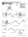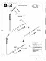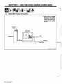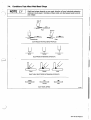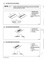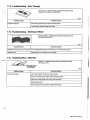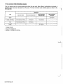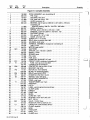
1
OM-187 925A
August
AUTO ARC L
Ifi
1998
Processes
~
MIG(GMAW)
Flux Cored
(FCAW)
Description
Wire Feeder
Auto Arc 120
For Technical
Milweld
P.O. Box
Support, Contact:
Inc., National Distributor
338, Hortonville, WI 54944-0338
Tel 920-779-0924 Fax 920-779-0924
OWNERS
MANUAL
0
SECTION 1
PRECAUTIONS-
-
EFQRE USING
READ
som_nd_5/97
Symbol Usage
1-1.
Means Warning! Watch Out! There are possible
hazards with this procedure! The possible hazards are
shown in the adjoining symbols.
a
A
~
~:
~.~T~:.
Marks
This group of
symbols means Warning! Watch Out! possible
ELECTRIC SHOCK, MOVING PARTS, and HOT PARTS hazards.
Consult symbols and related instructions below for necessary
actions to avoid the hazards.
special safety message.
a
~tT Means Note;
not
safety
related.
~
A
The
symbols shown
below
are
used
throughout this manual
to call attention to and Identify possible hazards. When you
seethe symbol, watch out, and followthe related instructions
to avoid the hazard. The
safety information given below is
more complete safety information
summary of the
found in the Safety Standards listed In Section 1-4. Read and
follow all Safety Standards.
only
a
A Only qualified persons should instail, operate, maintain, and
repair this unit.
A
During operation, keep everybody, especially children, away.
If earth
with
a
grounding
workpiece
is
do not
work
use
required, ground it directly
clamp or work, cable.
Do not touch electrode if you are in contact with the work,
another electrode from a different machine.
Use only well-maintained
parts
ground,
equipment. Repair or replace damaged
according to manual.
at once. Maintain unit
a safety harness if working above floor level.
Keep all panels and,covers securely in place.
Wear
Clamp work cable with good
worktable
as near
Insulate work
metal-to-metal contact to
the weld
as
workpiece
practical.
clamp when not connected
object.
to
workpiece to prevent
contact with any metal
Do not connect
electrical parts can cause fatal
shocks or severe burns. The electrode and work
circuit is electrically live whenever the output is on.
The input power circuit and machine internal
circuits are also live when power is on. In semiautomatic or
automatic wire welding, the wire, wire reel, drive roll housing, and all
metal parts touching the welding wire are electrically live. Incorrectly
installed or improperly grounded equipment is a hazard.
live
Touching
-
or
or
ill
of the
cable
separate
single
weld
more
than
one
electrode
or
work cable to any
output terminal.
SIGNIFICANT DC VOLTAGE exists after removal of
input power on inverters.
Turn Oft inverter, disconnect input power, and discharge input
capacitors according to instructions in Maintenance Section
before touching any parts.
Do not touch live electrical
parts.
dry, hole-free insulating gloves and body protection.
Wear
Insulate
yourself from work and ground using dry insulating mats
big enough to prevent any physical contact with the
ground.
ANP.~,S~S~an bardous.
or covers
work
or
Do not useAC output in
of
there is
a
Use AC
output ONLY
If AC
danger
output
is
damp areas, if movement is confined,
or
if
if
required,
required for
use
the
remote
welding
output control if present
on
input power or stop engine before installing or
equipment. Lockout/tagout input power according
OSHA 29 CFR 191 0.147 (see Safety Standards).
Properly
Owners
this
install and
Manual and
ground
this
equipment according
to its
national, state, and local codes.
Always verify the supply ground check and be sure that input
power cord ground wire is properly connected to ground terminal
in disconnect box or that cord plug is connected to a properly
grounded receptacle outlet.
-
When
making input connections,
conductor first
-
attach
proper
grounding
double-check connections.
Frequently inspect input power cord for damage or bare wiring
replace cord immediately if damaged bare wiring can kill.
-
-
Turn off all
Do not
Do not
use
equipment
worn,
drape
when not in
over
your body.
or
poorly spliced
out of the fumes. Do not breathe the fumes.
If inside, ventilate the area and/or
remove welding fumes and gases.
If ventilation is poor,
use an
Read the
Safety
cables.
Material
manufacturers
use
exhaust at the
arc
to
approved air-supplied respirator.
Data Sheets (MSDS5)
instructions for metals, consumables,
and
the
coatings,
cleaners, and degreasers.
confined space
Work in
a
wearing
an
only if it is well ventilated, or while
air-supplied respirator. Always have a trained watchperson nearby. Welding fumes and gases can displace air and
lower the oxygen level causing injury or death. Be sure the
breathing air is safe.
Do not weld in locations
operations.
form highly
near
degreasing, cleaning,
The heat and rays of the arc
toxic and irritating gases.
can
or
spraying
react with vapors to
coated metals, such as galvanized, lead, or
unless the coating is removed from the
weld area, the area is well ventilated, and if necessary, while
wearing an air-supplied respirator. The coatings and any metals
containing these elements can give off toxic fumes if welded.
Do not weld
cadmium
use.
damaged, undersized,
cables
=~i
Keep your head
process.
Disconnect
to
fumes and gases. Breathing
these fumes and gases can be hazardous to your
health.
falling~
unit.
servicing
Welding produces
on
plated steel,
OM-187 925
Page
1
canbu
Arc rays from the welding process produce intense
visible and invisible (ultraviolet and infrared) rays
that can burn eyes and skin. Sparks fly off from the
weld.
f__
S
Shut off
S
Always ventilate confined spaces
approved air-supplied respirator.
shielding gas supply when
not in use.
or
use
Wearawelding helmetfitted with a propershade of filterto protect
your face and eyes when welding or watching (see ANSI Z49.1
and Z87.1 listed in Safety Standards).
Wear
with side shields under your
approved safety glasses
helmet.
Do not touch hot
Use protective screens
glare;warn~others
Wear
or
barriers to protect others from flash and
not towatchthe
Allow
parts
bare handed.
before
coolingperiod
working
on
gun
or
torch.
arc.
protective clothing made from durable, flame-resistant
(leather and wool) and foot protection.
material
MAGNETiC PELDS can
~
(~.
Welding
on
closed
containers, such
Pacemaker
tanks,
as
going near arc welding, gouging,
welding operations.
them to blowup. Sparks
can fly off from the welding arc. The flying sparks,
hot .workpiece,and hot equipment can cause fires
and burns. Accidental contact of electrode to metal objects can
cause sparks, explosion, overheating, orfire. Check and be surethe
area is safe before doing any welding.
or
pipes,
can cause
yourself and others from flying sparks
Protect
Do not weld where
flying sparks
can
Remove all flammables within 35 ft
possible, tightly
this is not
cover
thatwelding sparks
easily go through small cracks
Watch for
fire, and keep
Be
that
aware
can cause
fire
Do not weld
on
welding
on
a
and
(10.7 m) of the welding
apprved
openings
Do not
closed containers such
prevent welding current
paths
use
as
tip
and
causing
when not in
Wear
welding
adjacent areas.
approved
ear
protection if noise
level is
xpiodeit dafl~aged~
partition
or
or
process, be sureto treat them
carefully.
Protect
Install cylinders in an upright position by securing to a stationary
support or cylinder rack to prevent falling or tipping.
pipes.
or
cut off
welding
compressed gas cylinders from excessive heat,
shocks, slag, open flames, sparks, and arcs.
mechanical
wire at
Keep cylinders away from any welding or other electricalcircuits.
such
as
a
leather
Never
gloves, heavy
cap.
lighter or matches,
~
Welding, chipping, wire brushing, and grinding
cause sparks and flying metal. As welds cool,
they can throw off slag.
approved safety glasses with side
shields even under your welding helmet.
drape
Never allow
Never weld
S
Wear
Shielding gas cylinders contain gas under high
pressure. If damaged, a cylinder can explode.
Since gas cylinders are normally part of the welding
I
pipes,
(see
to AWS F4. 1
welding area as
from traveling long, possibly
Remove any combustibles, such as a butane
from your person before doing any welding.
2
can
high.
use.
protective garments
Page
equipment
can
tanks, drums,
as
shirt, cuffless trousers, high shoes, and
OM-187 925
or
If
covers.
electric shock and fire hazards.
welder to thaw frozen
Wear oil-free
processes
close to the
Remove stick electrode from holder
contact
arc.
some
the hidden side.
Connect work cable to the work
to
to
extinguisher nearby.
ceiling, floor, bulkhead,
they are properly prepared according
Safety Standards).
unknown
Noise from
damage hearing.
fire
on a
unless
practical
spot
and hot metal.
and hot materials from
Be alert
or
~
;:~~
strike flammable material.
them with
keep away.
Wearers should consult their doctor before~
_____
drums,
wearers
affeqtpacemaker~
a
a
welding
welding
on a
torch
over a
gas cylinder.
electrode to touch any
pressurized cylinder
-
cylinder.
explosion
will result.
Use only correct shielding gas cylinders, regulators, hoses,
fittings designed for the specific application; maintain them
associated parts in good condition.
Turn face away from valve outlet when
opening cylinder
and
and
valve.
Keep protective cap in place over valve except when cylinder is in
use or
connected for
use.
Read and follow instructions
associated
Standards.
equipment,
compressed gas cylinders,
publication P-i listed in Safety
on
and CGA
~
~~
...~
.d(
~
~
~
...
~
~
~
.~4.
Do not install
A
place unit
or
Keep away from moving parts such
on, over, or near
combustible surfaces.
Do not install unit
near
as
all doors, panels, covers, and
closed and securely in place.
Keep
A
flammables.
fans.
guards
Do not overload
is
building wiring- be sure power supply system
properly sized, rated, and protected to handle this unit.
Use lifting eye to lift unit only, NOT running
gear, gas cylinders, or any other accessories.
~
High-frequency (H.F.) can interfere with radio
navigation, safety services, computers, and
communications equipment.
Have only qualified persons familiar with
electronic equipment perform this installation.
capacity to lift and
Use equipment of adequate
support unit.
Ifusing lift forks to move unit, be sure forks are
long enough to extend beyond opposite side of
unit.
The
is
user
responsible for having a qualified electrician
problem resulting from the
correct any interference
installation.
promptly
If notified
by
equipment
at once.
.
Allow
cooling period; follow
Reduce current or reduce
starting to weld again.
.
Do not block
rated
duty cycle.
duty cycle
regularly
interference, stop using the
checked and maintained.
Keep high-frequency source doors and panels tightly shut,
keep spark gaps at correct setting, and use grounding and
shielding to minimize the possibility of interference.
rds.:~
C
Put
Have the installation
before
filter airflow to unit.
or
the FCC about
on
handling
wrist
grounded
boards
or
strap
BEFORE
parts.
Use proper static-proof bags and boxes to
store, move, or ship PC boards.
Electromagnetic energy can interfere with
electronic equipment such
as
computers and computer-driven equipment
sensitive
such
Be
Keep away from moving parts.
Keep away from pinch points such
as
robots.
all equipment in the welding
electromagnetically compatible.
as
To reduce
drive
possible,
rolls.
sure
area
is
possible interference, keep weld cables as short as
together, and down low, such as on the floor.
close
______________
welding operation
equipment.
Locate
tronic
tIRE can cause
injury
Be
sure
according
Do not press gun
trigger
until instructed to do
this
welding
100 meters from any sensitive elec
machine
is installed
and
grounded
to this manual.
If interference still occurs, the user must take extra measures
as moving the welding machine, using shielded cables,
so.
such
point gun toward any part of the body,
people, or any metal when threading
welding wire.
using
Do not
line filters,
or
shielding
the work
area.
other
~
~
~
~
~
~
~
~
Principal Safety Standards
14.
N
N
Cutting, ANSI Standard Z49.1, from American
Safety
Welding
Welding Society, 550 NW. LeJeune Rd, Miami FL 33126
in
and
Safety and Health Standards, OSHA
29 CFR 1910, from
dent of Documents, U.S. Government
D.C. 20402.
Superinten
Printing Office, Washington,
Recommended Safe Practices for the Preparation for Welding and
Cutting of Containers That Have Held Hazardous Substances,
American Welding Society Standard AWS F4.i, from American
Welding Society,
550 N.W. LeJeune
Rd, Miami, FL 33126
National Electrical Code, NFPA Standard 70, from National Fire
Protection Association, Batterymarch Park, Quincy, MA 02269.
~
~
Safe Handling of Compressed Gases in Cylinders, CGA Pamphlet
P-i, from Compressed Gas Association, 1235 Jefferson Davis
Highway, Suite 501, Arlington, VA 22202.
Code for Safety in Welding and Cutting, CSA Standard Wi 17.2, from
Canadian Standards Association, Standards Sales, 178 Rexdale
Boulevard, Rexdale, Ontario, Canada M9W 1 R3.
Safe Practices For
Occupation
And Educational
Eye
And Face
Protection, ANSI Standard Z87.1 ,from American National Standards
Institute, 1430 Broadway, New York, NY 10018.
Cutting And Welding Processes, NFPA Standard 51 B, from National
Fire Protection Association, Batterymarch Park, Quincy, MA 02269.
OM-187 925 Page 3
Considerations About Welding And The Effects Of Low
Electric And Magnetic Fields
Frequency
1.
Keep cables close together by twisting
Welding current, as itfiows through welding cables, will cause electromagnetic fields. There has been and still issome concern about such
fields. However, after examining more than 500 studies spanning 17
years of research, a special blue ribbon committee of the National
Research Council concluded that: The body of evidence, in the
committees judgment, has not demonstrated that exposure to powerfrequency electric and magnetic fields is a human-health hazard.
However, studies are still going forth and evidence continues to be
2.
Arrange cables
3.
Do not coil
examined..lJntil the final conclusions of the research are reached, you
may wish to minimize your exposure to electromagnetic fields when
welding
cutting.To reduce magnetic fields
procedures:
4.
taping
to one side and away from the
drape
or
or
Keep welding power
practical.
cables around your
source
and cables
them.
operator.
body.
as
far away from opera-
tor as
s.
Connect work clamp to
workpiece
as
close to the weld
as
possible.
-
About Pacemakers:
or
in the
workplace,
use
the
following
Pacemaker wearers consult your doctorfirst. If cleared by yOur doctor,
then following the above procedures is recommended.
IT
OM-187 925
Page
4
SECTION 1. CONSIGNES DE SECYR,ITE. -LIRE AVANT.YTPLISAT!9,N
som
~
3.~..
~
SignifIcation dessymboles
1 1
43.~3~33.~~
~:
~
~
~.
-~
N
~
~
3.
~
_nd_Fre_4/97
~
.
Signifie Mise en garde! Soyez vigilant! Cette procedure
prØsente des risques de danger! Ceux-ci sont identifies
par des symboles adjacents aux directives.
r~
.
..
~
Ce groupe de
A
Identitle
1E7
Signifie
message
un
de sØcurltØ
symboles signifie Mise en garde! Soyez vigilant lIly ades
danger relies aux CHOCS ELECTRIQUES, aux PIECES EN
MOUVEMENTetauxPIECESCHAUDES. Reportez-vousauxsymboles
risques
particulier.
de
etauxdirectives ci-dessous afin de connaitre las
.J~. ~
A
Les
Øviter tout
NOTA ; nest pas re!atif Ia sØcuritØ.
-.
....
N.$~
-.
1..
.
N
risques
vigilant
danger.
sont utilisØs tout au long du
manuel pour attirer votre attention et identifier lea
de danger. Lorsque vous voyez un symbo!e, soyez
dØvlter tout
et sulvez lea directives mentionnØes atm
Los consignes de sØcurltØ prØsentØes cl-aprŁs ne font
lutlllsatlon, lentretlen et les reparations
Linstallatlon,
vent Œtre confiØs
A
Au
cours
do
qua
des personnos
no
F~orter
dol
toucher les
un
avec
Ia
harnais do sØcuritØ
piŁces Ølectriques
source
Ølectrique
humides, dans les endroits confines
Se servir dune
procede
de
source
soudage
sous
protection
secs ne
pince de masse quand
objet mØtallique.
Ily
Łlectrique
electrique dans es zones
risque de tomber.
Ølectrique UNIQUEMENT si le
l o
courant
on
-
que le fil de terre du cordon dalimentation est bien raccordØ a Ia
borne de terre du sectionneur ou que lafiche du cordon est raccordØe
correctement mise a Ia terre.
En effectuant les raccordements dentrØe fixer dabord le conducteur
de mise a Ia terre appropriØ et contre-vØrifier les connexions.
Verifier frØquemment le cordon dalimentation pour voir sil nest pas
endommage ou dØnudØ remplacer le cordon immØdiatementsiI est
endommage un cable dØnudØ peut provoquer une electrocution.
-
-
lappareil
panneaux et capots.
le
plus prŁs possible
de Ia
pas mis a
a
piŁce
pour Øviter Ia contact
aprŁs
Ia
suppression
de Ialimenta
Ølectrique.
tion
ArrŒter las convertisseurs, dØbrancher le courant
electrique, at dØ
charger les condensateurs dalimentation selon les instructions
indiquees dans Ia partie entretien avant de toucher les piŁces.
~
Lgs FUM~ES El LES ~tGAZ~peuvent~
Œtre dangereux ~
~
La soudage genere des fumØes et des gaz. Leur
inhalation peut Œtre dangereux pour votre sante.
=9
le demande.
hors tension
Ne pas utiliser des cables
sante ou mal ØpissØs.
hauteur.
DU COURANT CONTINU IMPORTANT dana les
a
convertisseurs
courant
ou
rer
Mettre
en
comportant
Couper lalimentation ou arrŒter le moteuravant de procØder Iinstal
lation, a Ia reparation ou a Ientretien de lappareil. DØverrouiller
lalimentation selon Ia norme OSHA 29 CFR 1910.147 (voir normes
de sŁcuritØ).
Installeret mettre a laterre correctement cetappareil conformØment
son manuel dutilisation et aux codes nationaux, provinciaux et
municipaux.
Toujours verifier Ia terre du cordon dalimentation Verifier et sassu
prise
tous los
travaille
tout
____________
une
place
on
tension.
Si Iutilisation dune source Ølectrique courant electrique savØre nØces
saire, se servir de Ia fonction de tØlØcommande Si lappareil en est equipØ.
a
~
ELEOTRIQUE peut tU~r.~
de Ia piŁce et de Ia terre au moyen de tapis ou dautres
moyens isolants suffisamment grands pour empØcher le contact phy
sique eventual avec Ia piŁce ou Ia terre.
servir de
quand
piŁce a souder ou latable do travail,
Sisoler
se
en
et plus par
Isoler Ia
Porter des gants et des vØtements de
pas de trous.
Ne pas
~
soudure.
Un simple contact avec des piŁces Łlectriques peut
provoquer une electrocution ou des blessures graves.
LŁlectrode et le circuit de soudage sont sous tension
des que lappareil est sur ON. Le circuit dentrØe et las
circuits internes de lappareil sont egalement sous
tension ace moment-l. En soudage semi-automatique ou automatique,
le flu, le dŁvidoir, le logement des galets dentraInement et les piŁces
rnetalliques en contact avec le fil de soudage sont sous tension. Des
matØriels mal installØs ou mal mis a Ia terre prØsentent un danger.
jamais
~
3~.
Fixer Ia cable de retour de facon a obtenir un bon contact mØtal-mØtal
avec
Ne
~
Maintenir solidement
ticullŁrement lea enfants.
UNCHOC
-.
ace manuel.
quallflØos.
Iutllisatlon, tenirtoute personno lØcart
a prendre pour
Nutiliser quun matØrlSl en bon Øtat. RØparer ou remplacer sur-le
champ les piŁces endommagŁes. Entretenirlappareil conformØment
quo rØsumer linformation contenue dans les normes do sØcurltØ
ØnumØrØes a Is section 1-5. Veulllez lire et respecter toutes ces
normes do sØcuritØ.
A
N.~
N
symboles prØsentØs cI-aprŁs
present
mesures
danger.
quand on ne lutilise pas.
uses, endommages, de grosseur insuffi
Ne pas enrouler les cables autour du corps.
Si IapiŁce soudOe doitØtre mise laterre, lefaire directementavec un
cable distinct
ne pas utiliser le connecteur de piŁce ou le cable de
Eloigner
votre
tŒte des fumØes. Ne pas respirer
les fumŁes.
A
IintŁrieur,
veau
ventiler Ia zone et/ou utiliser un Øchappement au ni
de Iarc pour IØvacuation des fumŁes et des gaz de soudage.
Si Ia ventilation est insuffisante, utiliser
tion dair homologue.
un
respirateur a
alimenta.
Ure IesspŁcificationsde sØcuritØ des matØriaux (MSDS5) et los ins
tructions du fabricant concernant los mØtaux, las consommables,
les revŁtements, las nettoyants et les degraisseurs.
Travailler dans
un
espaco fermØ seulement siI est bien ventilØ
ou
respirateur a alimentation dair. Demander toujours a
un surveillant d~imentformØ de so tenir a proximitØ. Des fumŁes et
des gaz de soudage peuvent dØplacer lair et abaisser le niveau
doxygene provoquant des blessures ou des accidents mortels.
Sassurer que lair de respiration no presente aucun danger.
Ne pas souder dans des endroits situØs a proximitØ dopŁrations do
degraissage, de nettoyage ou do pulverisation. La chaleur et les
rayons de larc peuvent reagir en presence de vapeurs et former
des gaz hautement toxiques et irritants.
Ne pas souder des mŁtaux munis dun revØtement, tels qua lacier
galvanisØ, plaque en p10mb ou au cadmium ~ moms quote revŁte
mont nait ete enlevØ dans Ia zone do soudure, que lendroit soit
bion ventilØ, et si nØcossairo, en portant un rospirateur a alimenta
en
portant
un
tion dair. Los rovŒtements at tous los mØtaux renformant ces ele
ments peuvent dØgager des fumØes toxiques en cas do soudage.
-
retour.
Ne pas toucher lØlectrode
terre
ou une
electrode
quand on est
proverlant dune
en
contact avec Ia
piŁce,
Ia
autre machine.
OM-187 925 Paae 5
~
~
F
(~Ea
x~~x~-~
-
LES RAYONS D~ LARC peuvent pro~
voquer des brOlures d~ns lee yeux et~
~
~~
de Iarc du procØdØ de soudage
des rayons visibles et invisibles intenses
(ultraviolets et infrarouges) susceptibles de provoquer
des brOlures dans los yeux et sur Ia peau. Des Øtincelles sont projetØes
pendant le soudage.
Le
U
rayonnement
gØnØre
Fermer lalirnentation du gaz protecteur
non utilisation.
Veitler loujours a bien aØrer les espaces confines
rateur dadduction dair homologue.
--
ou se
en
servir dun respi
Porter un casque de soudage muni dun Øcran do filtre appropriØ pour
protØger votre visage et vos yeux pendant le soudage ou pour regar
der (voir ANSI Z49.1 etZ87.1 ØnumØrØ dans les normes de sØcuritØ).
Porter des protections
approuvØs
pour los oreilles si le niveau sondre est
trop ØlevØ.
.
-.
-
Utiliser des Øcrans-ou des barriŁres pour proteger des tiers de lØclair
et de lØblouissement; demander aux autres personnes done pas re
garder
No pas toucher dos
ble, resistant
au
feu
PrØvoir une periode de refroidissement avant
dutiliser le pistolet ou Ia torche.
protection constituØ dans une matiŁre dura
(cuir ou lame) et une protection des pieds.
~I StE~SOUDA~E peut provoquer un
~ .ncendieou unee~plosiOn.
effectuØ sur des conteneurs fermØs tels
que des reservoirs, tambours ou des conduites peut
Le
soudage
I
I
I
-
provoquerleureclatement. DesetirtcellespeuveritŁtre
Porteurs de stimulateur cardiaque, restez a distance.
projetees do Iarc de soudure. La projection dØtincel
les, des piŁces chaudes et des equipements chauds peut provoquerdes
incendies et des brlures. Le contact accidentel de JŁlectrode avec des
Los porteurs dun stimulateur cardiaque doivent
dabord consulter leur mØdecin avant do sapprocher
des operations do soudage a larc, do gougeage ou
des Œtincelles, une explosion, un
surchauffement ou un incendie. Avant de commencer to soudage,
verifier et sassurer que lendroit no prŁsente pas do danger.
oblets metalliques peut prbvoquer
Se proteger et dautres
metal chaud.
personnes de Ia
Ne pas souder dans un endroit l o
sur des substances inflammables.
projection dØtincelles
des Øtincelles
.ment passer dans dautres
des ouvertures.
zones en traversant
de
do
soudage
peuvent tomber
.
Le bruit des processus et dos
loule.
Porter des
______________
soudage effectuØ sur un plafond, plancher, paroi ou separation
peut dØclencher un incendie de lautre ctØ.
Ne pas effectuer le soudage sur des conteneurs fermØs tels quo des
reservoirs, tambours, ou conduites, a moms quits naient ØtØ prepa
rØs correctement conformØment a AWS F4.1 (voir los normes de
Le
sØcuritØ).
Brancher le cAble sur Ia piŁce le plus prŁs possible de Ia zone de sou
dage pour Øviter le transport du courant sur une longue distance par
des chemins inconnus Øventuels en provoquant des risques dØlec
trocution et dincendie.
poste de soudage pour dØgeler des conduites go
utilisation, enlever Ia baguette dØlectrode du porte
couper le fit a Ia pointe de contact.
Porter des vetements do protection dØpourvus dhuile tels que des
gants en cuir, une chemise en matØriau lourd, des pantalons sans re
vers, des chaussures hautes et un couvre chef.
de
protections approuvØs
trop ØlevØ.
affecter
pour les oreilles si
petites fissures et
~
o
cas
equipemonts pout
le niveau sondre est
mite.
En
points.
L~ BRUIT peut affecter route
SurveillertoutdØclenchementdincendieettenirunextincteurproxi
No pas utiliser le
lees.
par
et de
DØplacertoutes los substances inflammables a une distance de 10,7
m de larc do soudage. En cas dimpossibilitØ los rocouvrir soigneuse
ment avec des protections homologuØs.
Des Łtincelles et des matØriaux chauds du soudage peuvent facile
electrode
chaudes a mains
-
Porter des vŒtements de
m
parties
flues
larc.
non
ou
Avant do souder, retirer toute substance combustible de
telles quun allumeur au butane ou des allumettes.
vos
poches
y~:
I --Sides-BO.UTElU~ES-~æt~ºædOin
gees5 eues pourro~t e~p~oser
f~
I ~
U
~
Des bouteilles do gaz protectour contionnent du gaz
haute prossion. Si uno bouteille ost endomma
gee, elle pout exploser. Du faitque les bouteillesdegaz
font normaloment partie du procedØ do soudago, les
sous
___________
manipuler
avec
precaution.
ProtØger los bouteitles de gaz comprimØ dune chateur excessive,
des chocs mecaniques, du laitier, des flammes ouvertes, des Øtin
cellos et des arcs.
Placer los bouteilles debout en los fixant dans un support station
nairo ou dans un porte-boutoilles pour los empecher do tombor ou
de
se renverser.
Tenir los bouteilles
cults electriques.
Ne
jamais placer
Une electrode do
une bouteille.
Ne
DES PARTICULES VOLANT~S
~
~
jamais
souder
ØloignØes des circuits do soudage ou autres cir
une
torche de
soudage
une
no
soudage sur une bouteille a gaz.
jamais entrer en contact avec
doit
bouteille
pressurisŁe
-
risque doxplosion.
Utiliser seulemont des bouteilles do gaz protectour, regulateurs,
tuyaux et raccords convenables pour cette application spØcifique;
los maintenir ainsi quo los ŁlŁments associØs en bon Øtat.
Ne pas tenir Ia tŒte en face do Ia sortie en ouvrant Ia soupapo do Ia
bouteille.
Le
le passage de Ia piŁce
et le meulage gØnerent
soudago, lØcaillement,
a Ia brosse en fil do fer,
desØtincellesetdes particules mŁtalliquesvolan
tes. Pendant Ia
de
pØriode de refroidissement des soudures,
elles
risquent
projeter du laitier.
Porter des lunettes de sØcuritØ
OM-1 87 925
Page
6
avec
Øcrans tatØraux
ou un
Øcran facial.
Maintonir le chapeau do protection sur Ia soupape, sauf
dutilisation ou de branchement do Ia bouteille.
en cas
Lire ot suivre les instructions concernant les bouteilles do gaz corn
los equipements associØs et los publications P-i CGAØnu
mØrØes dans los normes do sŁcuritØ.
prime,
(
I ~3
Dangerssupplementairesenrelation
et Ia
Al
.4.
avec
I
A
D
Ne pas
A
font,On~ent~~~
Iinstailatirnje
maintenance
placer lappareil
proximitØ
sur, au-dessus
ou
A
Rester A lØcart des organes mobiles
ventilateur.
de surfaces infilammables.
I
pas installer lappareil a proximitØ de produits inflammables
Ne pas surcharger linstallation Ølectrique sassurer que lalimen
tation esVcorrectement dimensionnØ et protØgØ avant de mettre
lappareilen service.
-.Ne
MaintenirfermØs etfixement
panneaux,
en
recouvrements
et
comme
le
place les portes,
dispositifs de
-
___________________
protection.
~
LA ~HUTE DE LAPPAREIL
peut
_______
Lerayonnementhautefrequence pout provoquer
avec los Øquipements de ra
dio-navigation etdecommunication, les services
des interferences
Utiliser lanneau de levage uniquement pour sou
lever lappareil, NON PAS les chariot, les bouteil
les de gaz ou tout autre accessoire.
_____________
Utiliser un engin dune
soulever lappareil.
capacitØ appropriØe
pour
tiOn.
En utilisant des fourches de levage pour dØplacer lunitØ, sassurer
que les fourches sont suffisamment longues pourdØpasserdu ctØ
oppose de lappareil.
L~E~ILOI
de sØcuritØ et les ordinateurs
Demander seulement a des personnes qualifiØes familiarisØes
avec des equipements electroniques de faire fonctionner Iinstalla
E~IF peut
~
PrØvoir
une pØriode de refroidissement, respec
cycle opØratoire nominal.
RØduire le courant ou le cycle operatoire avant de
recommancer le soudage.
Lutilisateur est tenu de faire corriger rapidement par
les interferences resultant de linstallation.
un
Ølectricien
qualifie
Si le FCC
red.
signale des interferences, arrŒter immØdiatement lappa.
Effectuer
reguliOremont
le contrle
et lentretien de Iinstallation.
Maintenir soigneusement fermØs los portes et les panneaux des
sources de haute frØquence, maintenir les Øclateurs a une distance
correcte et utiliser une terre et et un blindage pour rØduire les inter
fØrences Øventuelles.
ter le
Ne pas obstruer les passages dair du paste.
LØnergie
________
_____________
Etablir Ia connex~
de terre
~
~
ØlectromagnØtique
Ne pas
sapprocher
pas sapprocher
lØquipement de Ia zone de soudage soit com
patible electromagnetiquement.
Pour rØduire Ia possibilitØ dinterfØrence, maintenir les cables de
soudage aussi courts que possible, los grouper, et les poser aussi
bas que possible (ox. par terre).
Veiller a ce que ce paste de soudage soit
conformØment a ce mode demploi.
des organes mobiles.
Ne
des points de coincement
tels que des rouleaux de commande.
de
Veiller ace que tout
Veiller a souder a une distance de 100 metres de tout
electronique sensible.
p rovoque~ desbl~ssures
risque
provoquer des interferences pour lequipement
Ølectronique sensible tel que los ordinateurs et
lequipement commandØ par ordinateur tel que
los robots.
pose
Øquipement
et mis a Ia terre
En cas dinterfØrences aprŁs avoir pris les mesures prØcØdentes il
inconibe a lutilisateur de prendre dos mesures supplementaires
telles que le dØplacement du paste, lutilisation de cAbles blindØs.
lutilisation de filtres de ligne ou Ia pose de protecteurs dans Ia zone
de travail.
.oqt!ersJ~Jessures.
Ne pas appuyer sur Ia
recu linstruction.
Ne pas
diriger
le
sonnes Cu toute
le fil de
gachette
pistolet
vers
avant den avoir
soi, dautres per
piŁce mØcanique en engageant
soudage.
Les porteurs dun stimulateur cardiaque doivent
dabord consulter leur mØdecin avant do sappro
cher des operations de soudage a larc, de gou
geage
ou
do
soudage
par
points.
OM-187 925 Paae7
14
~
~
Principales
~----,~
normes de sØur.tØ
-~-~--
*
Safety in Welding and Cutting, norme ANSI Z49.i de lAmerican
ding Society, 550 NW. Lejeune Rd, Miami FL 33126
,
Wel
Safe
Handling
of
Compressed
Gases in
Cylinders,
CGA
.~
Pamphlet
P-i, de Ia Compressed Gas Association, 1235 Jefferson Davis High
way, Suite 501, Arlington, VA 22202.
Safetyand Health Sandards,
OSHA 29 CFR 1910, du Superintendent
of Documents, U.S. Government Printing Office, Washington, D.C.
20402.
RŁgles de sOcuritØ en soudage, coupage et procØdes connexes,
Recommended Safe Practice forthe Preparation for Welding and Cut
of Containers That Have Held Hazardous Substances, norme
AWS F4. 1, de lAmerican Welding Society, 550 N.W. Lejeune Rd, Mia
Safe Pra ctices ForOccupationAndEducationalEyeAndFaceProtec
ting
mi FL 33126
I ,5
tion,
Information
.
~
Cutting and Welding Processes, norme NFPA 51 B, de laNational
Protection Association, Batterymarch Park, Quincy, MA 02269.
~
--
lorganisme,
1
Garder les cblŁs ensembles en les torsadant
attachant avec du ruban adhØsif.
2
Mettre tous les cØbles du ctØ
3
Ne pas courber pas et
-
8
Fire
Afin de rØduire les champs ØlectromagnØtiques dans lenvironnement
de travail, respecter les consignes suivantes
Lextrait suivant esttirØ des conclusions gØnØrales du document intitu
lØ Biological Effects of Power Frequency Electric & Magnetic Fields
Background Paper, OTA-BP-E-53 (Washington DC: U.S. Govern
ment Printing Office; mai 1989), publiØ par le Office of Technology
Assessment du CongrŁs amØricain : ... II existe maintenant dabon
dantes donnØes scientifiques compilØes a Ia suite dexpØriences sur
Ia cellule ou dØtudes sur des animaux et des humains, qui montrent
clairement que les champs OlectromagnØtiques basse frequence peu
et mŒme y produire des
vent avoir des effets sur lorganisme
transformations. MØme sil sagit de travaux de trŁs grande qualite, les
rØsultats sont complexes. Cette dØmarche scientifique ne nous permet pas dØtablir un tableau densemble coherent. Pire encore, elle ne
nous permet pas de tirer des conclusions finales concernant les ris
ques Øventuels, ni doffrir des conseils sur les mesures a prendre pour
rØduire sinon Øliminer les risques Øventuels. (Traduction libre)
Page
Z87.i, de lAmerican National Standards Institute,
New York, NY 10018.
spur I~s champs ØiectromagnØtlques
DonnØes sur le soudage electrique et sur les effets, pour
des champs magnetiques basse frØquence
OM-187 925
ANSI
norme
1430Broadway,
National Electrical rode, NFPA Standard 70, de Ia National Fire Pro
tetion Association, Batterymarch Park, Quincy, MA 02269.
nor-
CSA Wi 17.2, de lAssociation canadienne de normalisation, vente
de normes, 178 Rexdale Boulevard, Rexdale (Ontario) Canada M9W
1 R3.
me
ne
oppose
de
ou en
les
IopØrateur.
pas entourer pas les cables autour de
vous.
4
Garder le poste de
de
soudage
et les cables le
plus
loin
possible
vous.
-
5
Relier Ia
pince de
masse
le
plus prŁs possible
de Ia
zone
de
soudure.
Consignes
relatives
aux
stimulateurs
cardiaques
Les consignes mentionnØes prØcØdemment font partie de celles desti
nØes aux personnes ayant recours a un stimulateur cardiaque.
Veuillez consulter votre mØdecin pour obtenir plus de details.
SECTION 2- SPECIFICATIONS,.
Specifications
2-1.
Rated
Welding
Output
Maximum Opencircuit voltage
Amperage
Range
Amperes Input at
Output
115 V, 60 Hz,
Single-Phase
Rated Load
Overall
Dimensions
Weight
KW
KVA
W/ Gun
Length: 17 in
(432 mm)
.
.
90 A
@ 18 Volts DC,
20%
30
-
130
20
28
Duty Cycle
(0.59)*
2.8
2.4
69 lb
Width: lOin
0.86*
0.043*
(31 kg)
(254 mm)
Height: 15-1/2
in
(394 mm)
.023
*
While
2-2.
-
-
.030 in
0.8
mm)
Wire Feed
Aluminum
Stainless
(0.6
Cored!
Flux
Solid!
Wire Type
And Dia
.030
(0.8
-
.035 in
0.9
-
220
-
Speed Range
700 1PM
mm)
(5.6
At No Load
18
-
m/min)
idling
Duty Cycle And Overheating
Duty Cycle
160
is
percentage of 10
miæute~ that unit can weld at rated
load without overheating.
If
100
unit
overheats, thermostat(s)
opens, output stops, and coolIng
fan runs. Wait fifteen minutes for
unit to cool. Reduce amperage or
~76
duty cycle before welding.
A
~6o
~3Z6
Exceeding duty cycle can
damage unit orgun and void
warranty.
25
0
10
16
202530
405060708090100
X DUTY CtcLE
20%
2 Minutes
Duty Cycle
At 90
Amperes
8 Minutes
Welding
Resting
Overheating
AorV
-*
OR
Reduce
-+~
Duty Cycle
Minutes
dutyl 4/95
-
SB-124 655-B
OM-187 925
Page
9
2-3.
Volt-Ampere Curves
50
The volt-ampere curves show the
minimum and maximum voltage
and amperage output capabilities
of the welding power source.
40
Curves of other settings fall be
tween the curves shown.
-
~30
0
>
20
u
0
10
ANGE 2
RANGE
1
0
0
20
40
60
80
100
120
140
160
180
200
DC AMPERES
ssbl.l 10/91 -SB-185560
SECTION~3
3-1.
SelectIng
-
INSTALLATION
A Location
Label
1
Rating
2
Grounded
A 115
branch circuit
18 in
(460 mm)
delay fuses
required.
3
Receptacle
volt, 20 ampere individual
timecircuit breaker is
protected by
or
Plug From Unit
Select extension cord of 12 AWG
for up to 75 ft (23 m) or 10 AWG for
upto 140ft(46m).
A Special Installation may be
required where gasoline or
volatile liquids are present
-
NEC Article 511
SectIon 20.
see
(460 mm)
OM-187 925
Page
10
or
CEC
1
3-2.
Installing
Work
Clamp
1
Insulator
2
Bolt
3
Smaller Hole
4
Work
Clamp
Tabs
Bend tabs around work cable.
Tools Needed:
5
Work Cable From Unit
6
Nut
2
3/8,7/l6in
Ref. ST-025 190-0
Installing Welding Gun
And
Changing Polarity
OM-187 925
Page
11
3-4.
Installing
Gas
Supply
Obtain gas cylinder and chain to
running gear, wall, orotherstation
ary support so cylinder cannot fail
and break off valve.
Tools Needed:
~
5/8, 1-1/8 in
1
Cap
2
Cylinder
Valve
Remove cap, stand to side of
valve, and open valve slightly. Gas
flow blows dust and dirt from valve.
Close valve.
2
3
Cylinder
4
Regulator/Flowmeter
Install
5
so
face is vertical.
Gas Rose Connection
Fitting has 5/8-18 right-hand
threads. Install gas hose.
6
Flow
Adjust
3
Typical flow rate is 20 cTh (cubic
feet per hour). Check wire man
ufacturers
recommended
flow
rate.
Argon Gas
1
7
CO2 Adapter
8
0-Ring
Install adapter with 0-ring between
and
regulator/flowmeter
CO2
cylinder.
OR
2
4
CO2
OM-187 925 Page 12
Gas
3.5.
Installing
Wire
Spool
And
Adjusting
Hub Tension
OM-187 925
Page
13
3-6.
Installing
Drive Roll, Wire Guide And
Threading Welding
Wire
Tools Needed:
Drive roll
1
Choose correct drive roll for wire
type, and align drive roll with flat
spot on shaft. Slide drive roll onto
shaft and secure with screw.
Inlet Wire Guide
2
guide by pressing on
cutting off one end
near housing and pulling it out of
hole. Push new guide into hole
from rear until it snaps in place.
Remove
barbed
area or
2
6 in
(150 mm)
Pull and hold
Open pressure assembly.
wire;
Push wire thru
cut off end.
guides
into gun;
continue to hold wire.
p~
-e
-,
Close and
Remove gun nozzle and contact
tighten pressure
assembly, and let go of wire.
trigger
comes
until wire
out of gun.
Turn power
tip.
on.
-4
-,
Press gun
-*
Reinstall contact
tip,
and nozzle.
Feed wire to check drive roll
perssure.
enough
to
Tighten
knob
prevent slipping.
Cut off wire. Close door.
Ret. ST~8O1 868/ Ref. ST-801 872 / Ret. 187 919 / S-0627-A
OM-187 925
Page
14
Weld Parameter
3-7.
Material Thickness
n
Wire
Wire
Type,
ShIelding Gas,
Diameter
And Flow Rate
(Inch)
e
ator
Controls
3/16 In
1/8 In
(4.8
mm)
(3.2
mm)
14 ga
4
4
3
2
60
55
50
4
4
60
4
Voltage Tap*
20 ga
22 ga
2
1
1
50
45
40
40
3
2
2
1
1
50
45
45
35
30
30
4
3
2
2
1
1
1
20
16 ga
18 ga
24 ga
.
--
.023
Wire
E7OS-6
Speed
--
CO2
20 cfh+
Voltage Tap*
-
-
.030
Wire
Speed
Voltage Tap*
--
~
.023
E70S6
80
75
60
55
50
45
30
4
4
3
2
2
1
1
70
65
60
55
50
45
30
4
4
3
2
1
50
40
30
25
20
Voltage Tap*
4
4
3
2
WireSpeed
40
35
30
25
4
4
80
Wire
Speed
75%
Argon
25% CO2
Voltage Tap*
--
.030
Wire
Speed
Voltage Tap*
--
-
--
--
.030
Wire
E71T-GS
Speed
Flux Core
--
-
-
--
.
--
--
--
--
--
--
--
--
3
3
3
3
75
75
70
65
60
4
4
3
3
3
3
75
70
70
65
60
50
4
4
3
100
100
100
--
--
4
4
4
100
100
100
.035
Voltage Tap*
308L Stainless
90% Helium
7.5%
2.5%
.023
Argon
CO2
2ocfh
Wire
~
Speed
--
Voltage Tap*
--
-
-
.030
Wire
Speed
--
Voltage Tap*
--
.030
Wire
5356AL
100% Argon
20 cfh
Speed
--
Voltage Tap*
--
--
--
--
.035
Wire
*Do not
change Voltage switch position
during welding.
fine tuned
Speed
while
welding.
--
Wire
Speed
value in Table is
a
starting
value
--
only,
and Wire
--
Speed
control
setting
can
be
Ref. S.186 225-B
OM-187 925
Page
15
SECTION 4-OPERATION
4-1.
Controls
WIRE SPEED
VOLTAGE
OM-187 925
Page
16
SECTION 5- MAINTENANCE &TRQUB~
5-1.
Routine Maintenance
5-2.
Drive Motor Fuse Fl
QOTING
A Turn Off power,
door and
remove
1
Circuit Board PCi
2
Fuse Fl
(See
unlatch
wrapper.
Parts List For
Rating)
If drive motor is inoperative, pull
fuse from fuse holder on PCi. Re
place fuse if necessary. To rein
stall, push fuse into fuse holder.
Reinstall wrapper, and latch door.
Tools Needed:
~r
3/8in
ST.801 887
5-3.
Short Circuit Shutdown
If contact
trigger,
tip
is shorted and sticks to
turn Off
continue
unit, and
remove
workpiece, the unit shuts down, but fan runs. To resume operation, release gun
tip from workpiece. Check contact tip and replace if damaged. Turn On unit to
contact
operation.
OM-l87 925
Page
17
5-4.
Cleaning
Or
Repairing Drive Assembly
F?1 ~*~H1r~
~
~
Off
Turn
A
Tools Needed:
power
before
cleaning or repairing
assembly.
5/64 in
1
Wire
2
Nozzle
Cut
welding
drive
Spool
wire off at nozzle. Re
spool and secure.
tract wire onto
3
Pressure Roll Arm
4
Cotter Pin
5
Pin
6
Screw
7
Bearing
Remove
ing and
stall
arm
cotter
Install new bear~
with screw. Rein
onto pin and secure with
bearing.
secure
pin.
8
Screw
9
Drive Roll
Remove drive roll.
drive roll with flat spot on
shaft. Slide drive roll onto shaft and
secure with screw.
Align
10
Wire Inlet Guide
guide by pressing on
cutting off one end
near housing and pulling it out of
hole. Push new guide into hole
from rear until it snaps in place.
Remove
barbed
area or
Close door.
Ref. ST-801 991 I Ref. ST-801 872
5-5.
Replacing
Gun Contact
Tip
Vt ~#H
A Turn Off power before
replacing contact tip.
1
Nozzle
2
Contact
Tip
Cut off welding wire at contact
Remove nozzle.
Remove contact tip and install
tip. Reinstall nozzle.
tip.
new
contact
Tools Needed:
2
Ref. ST-801 872
OM-187 925
Page
18
5-6.
Cleaning
Or
Replacing Gun
Liner
Tools Needed:
A
Disconnect gun from unit.
r
3/8in
Head Tube
3/8 in
Remove nozzle, contact
tip,
and liner collet.
3/8
Remove liner.
1~
To Reassemble Gun:
Install contact
tip.
Lay gun cable out straight before
installing new liner.
Insert
new
liner.
Gun/feeder
Install coVet onto liner and
connector
into
Blow out gun
casing.
gun/feeder
connector
tighten
using
wrench.
Cut liner off near collet so that liner
end is as close to drive rolls as pos
sible without touching.
Install nozzle.
Ref. ST-155 509
OM-187 925
Page
19
Troubleshooting
5-7.
Table
~i$~H$~ m~
Trouble
Remedy
No weld output; wire does not feed;
does not run.
fan
Secure power cord
plug
line fuse
Replace building
Secure gun
in
trigger plug
in
Place Power switch in On
No weld
output; wire
motor continues to
does not
feed; fan
run.
Thermostat TP1 open
Section 2-2).
Check and
Have
No weld
output; wire feeds.
replace
Factory
or
receptacle (see Section 3-3).
position (see Section 4-1).
contact
to
get good
Connect unit to proper
output.
Place
Electrode wire
feeding stops during
welding.
voltage
cable and/or
.
Adjust
drive roll pressure
Change
Replace
Clean
hub tension
contact
metal to metal contact.
polarity changeover
tip
or
check for low line
position (see
pressure
Check motor fuse Fl, and
Owners
(see gun
or
liner if
bearing
if
or
Page
20
dirty
Manual).
Manual).
or
worn or
plugged (see
slipping (see
repair leads,
or
gun Owners
Section
Manual
5-4).
replace trigger switch (see Section 3-3 and/or
replace if necessary (see Section 5-2).
Check and clear any restrictions at drive
and/or Section 5-4).
OM-187 925
4-1).
(see Section 3-5).
if blocked
Factory
voltage.
(see Section 3-6).
Secure gun trigger plug in receptacle
gun Owners Manual).
Have nearest
Section
(see Section 3-3).
(see Section 3-6).
replace wire inlet guide
and/or Section 5-4).
drive roll
or
board
replace damaged parts (see gun Owners
or
Replace
check all board connections and shut down PCi board.
Agent
to proper drive roll groove
Readjust
(see Section 5-2).
if necessary
input voltage
switch in desired
Straighten gun
(see
tip (see gun Owners Manual).
Check for proper connections at
Low weld
Allow fan to run; thermostat closes when unit has cooled
(overheating).
motor fuse Fl
clamp
3-1).
reset circuit breaker if open.
Authorized Service
Connect work
Replace
receptacle (see
Section
assembly
Authorized Service
and liner
Agent check
(see gun Owners
drive motor.
Manual
SECTION 6- ELECTRICAL DIAGRAM
ii
.4
0
>
=
C
z
C,
n
SB-ISO 204
Figure
6-1. Circuit
Diagram
OM-187 925
Page
21
SECTION 7
7-1.
MIG WELDING
(GM~W) GUIDELINES
Typical MIG Process Connections
A
Weld current can damage
electronic parts in vehicles.
both
Disconnect
battery
cables before welding on a
vehicle. Place work clamp
as close to the weld
as
possible.
Regulator/
Flowmeter
Wire Feeder/
Power Source
Gun
Shielding
Gas
Workpiece
Work
Clamp
light mig 5/967/ ST-801
OM-187 925
Page
22
909
7-2.
Typical MIG
Process Control
NOTE 1t~
Settings
settings are guidelines only. Material and wire type, joint design, fitup,
position, shielding gas, etc. affect settings. Test welds to be sure they comply to
specifications.
These
Material thickness determines
1/8
parameters.
or
125 in
Convert Material
Thickness to
Amperage (A)
(.001 in
=
.125 in
Wire Size
1
ampere)
=
125A
Amperage Range
.023in
30-90A
.O3Oin
40-145A
.035in
50-180A
Select Wire Size
1~
Select Wire
Speed
(Amperage)
Wire
Speed
(Approx.)
Wire
Recommendation
Size
.023 in
3.5 in per ampere
.O3Oin
2inperampere
.035 in
1.6 in per ampere
3.5
x
125 A
=
437
1pm
2x125A=2SOipm
1.6
x
125 A
=
200
1pm
l25Abasedon 1/8 in
material thickness
1pm
=
inch per minute
4,4
Low
voltage:
High voltage:
Set
arc
voltage midway
Voltage controls
weld bead.
wire stubs into work
is unstable
between
height and
(spatter)
Select
Voltage
high/low voltage.
width
Ref. ST-801 865
OM-187 925
Page
23
7-3.
Holding
N OTE
And
1EI~
Positioning Welding
Gun
Welding wire is energized when gun trigger is pressed. Before lowering helmet and
pressing trigger, be sure wire is no more than 1/2 in (13 mm) past end of nozzle,
and tip of wire is positioned correctly on seam.
1
1
Hold Gun and Control Gun
Trigger
2
Workpiece
3
Work
4
Electrode Extension
Clamp
(Stickout) 1/4
13mm)
5
()
Angle
1/2 in (6 To
Cradle Gun and Rest Hand
on
End View Of Work
to
Workpiece
S
Side View Of G un
Angle
~
GROOVE WELDS
End View Of Work
Angle
Side View Of Gun
Angle
FILLET WELDS
S-0421-A
OM-187925Page24
7-4.
Conditions That Affect Weld Bead
N OTE
iti~
Shape
shape depends on gun angle, direction of travel, electrode extension
speed, thickness of base metal, wire feed speed (weld current),
(stickout),
and voltage.
Weld bead
travel
100
Push
100
p
Drag
Perpendicular
GUN ANGLES AND WELD BEAD PROFILES
L~J
L5J
Short
Normai
ELECTRODE EXTENSIONS
Short
Long
(STICKOUT)
Normal
Long
FILLET WELD ELECTRODE EXTENSIONS
(STICKOUT)
S
Slow
Normal
S
Fast
GUN TRAVEL SPEED
S-0634
OM-1 87 925
Page
25
7-5.
Gun Movement
During Welding
I
I
N OTE
~
I
I
Normally,
a
single stringer bead is satisfactory for most narrow groove weld joints;
or bridging across gaps, a weave bead or
however, for wide groove weld joints
multiple stringer beads works better.
1
Stringer
Bead
Movement
1
2
2
Weave Bead
Movement
~
3
Steady
Along Seam
-
-
Side To Side
Seam
Along
Weave Patterns
Use weave patterns to cover a
wide area in one pass of the
electrode.
k(~:((4:~(( ~
S-0054-A
7-6.
Poor Weld Bead Characteristics
1
Large Spatter Deposits
2
Rough, Uneven Bead
3
Slight
4
Bad
5
Poor Penetration
:1
Crater
During Welding
Overlap
5
S-0053-A
7-7.
Good Weld Bead Characteristics
1
1
Fine
2
Uniform Bead
3
Spatter
Moderate Crater
During
Welding
Weld
1/8 in
a new
bead or layer for each
(3.2 mm) thickness in metals
being
welded.
Overlap
4
No
5
Good Penetration into Base
Metal
S-0052.B
OM-187 925 Page 26
/~Th)
7-8.
Troubleshooting
.
..
-.
~
.
-
Excessive
Spatter
Excessive Spatter scattering of molten metal
cool to solid form near weld bead.
I
.
-
-.
particles that
S-o638
-
Possible Causes
Wire feed
Voltage
speed
too
too
Corrective Actions
Select lower wire feed speed.
high.
Select lower
high.
Electrode extension
(stickout)
too
long.
voltage range.
Use shorter electrode extension
(stickout).
Remove all grease, oil, moisture, rust,
Workpiece dirty.
paint, undercoating,
and dirt from work surface before
welding.
insufficient
shielding gas
Dirty welding
at
welding
arc.
wire.
Increase flow of
Use clean,
Eliminate
7-9.
Troubleshooting
-
shielding gas
dry welding
pickup of
oil
regulator/flowmeter and/or prevent drafts
at
near
welding
arc.
wire.
or
lubricant
welding
on
wire from feeder or liner.
Porosity
Porosity
-
small cavities
or
holes
resulting from gas pockets
in weld metal.
S-0635
Possible Causes
Insufficient
shielding gas
at
welding
Corrective Actions
arc.
Increase flow of
Remove
shielding gas
spatter from gun
at
regulator/flowmeter and/or prevent
drafts
near
welding
arc.
nozzle.
Check gas hoses for leaks.
Place nozzle 1/4 to 1/2 in
Hold gun
Use
Wrong gas.
Dirty welding
wire.
bead at end of weld until molten metal solidifies.
welding grade shielding gas; change
Use clean,
Eliminate
Workpiece dirty.
near
(6-13 mm) from workpiece.
dry welding
pick up
of oil
Remove all grease,
to different gas.
wire.
or
lubricant
on
welding
wire from feeder
or
liner.
oil, moisture, rust, paint, coatings, and dirt from work surface before
welding.
Use
Welding
wire extends too far out of nozzle.
Be
a more
sure
highly deoxidizing welding
welding
wire extends not
more
wire
(contact supplier).
than 1/2 in
(13 mm) beyond
nozzle.
OM-1 87 925
Page
27
7-10.
TroubleshootIng
-
Excessive Penetration
I
Excessive Penetration weld metal
and hanging underneath weld.
-
(
Excessive Penetration
)
V
melting through base metal
1
Good Penetration
S-0839
Corrective Actions
Possible Causes
Excessive heat
Select lower
input.
voltage range
Increase travel
7-11.
Troubleshooting
-
and reduce wire feed
speed.
speed.
Lack Of Penetration
Lack Of Penetration
shallow
fusion between weld metal and
-
Tr
)
~
I I
Lack of Penetration
base metal.
Good Penetration
S-0638
Possible Causes
Corrective Actions
Material too thick. Joint preparation and design must provide access
maintaining proper welding wire extension and arc characteristics.
Improper joint preparation.
Improper
weld
Maintain normal gun
technique.
Keep
Be
Insufficient heat
arc on
sure
Select
input.
leading edge
welding
Troubleshooting
-
of 0 to 15
of weld
wire extends not
wire feed
higher
Reduce travel
7-12.
angle
degrees
to achieve maximum
to bottom of groove while
penetration.
puddle.
more
than 1/2 in
(13 mm) beyohd nozzle.
speed and/or select higher voltage range.
speed.
Incomplete Fusion
Incomplete
Fusion
base metal
or a
-
failure of weld metal to fuse
weld bead.
completely
with
preceeding
S-0637
Possible Causes
Corrective Actions
Remove all grease, oil, moisture, rust,
Workpiece dirty.
paint, undercoating,
and dirt from work surtace before
welding.
Insufficient heat
input.
Improper welding technique.
Select
Place
higher voltage range and/or adjust
stringer bead in proper location(s)
Adjust work angle
hold arc
Keep
leading edge
arc on
at
speed.
loint during welding.
widen groove to access bottom
Momentarily
Use correct gun
OM-187 925 Page 28
or
wire feed
on
angle
groove side walls when
of weld
of 0 to 15
puddle.
degrees.
during welding.
using weaving technique.
7-13.
Troubleshooting
-
Burn-Through
~tely through
base metal
S-0640
Corrective Actions
Possible Causes
Excessive heat
Select lower
input.
voltage range
increase and/or maintain
7-14.
Troubleshooting
-
and reduce wire feed
steady
travel
speed.
speed.
Waviness Of Bead
Waviness Of Bead weld metal that is not parallel and does not cover
base metal.
-
joint formed by
S-0641
Corrective Actions
Possible Causes
Welding
wire extends too far out of nozzle.
Unsteady hand
7-15.
Be
sure
Support
TroUbleshooting
-
welding
hand
on
wire extends not
solid surface
more
or use
than
1/2 in (13 mm) beyond nozzle.
two hands.
Distortion
Distortion
contraction of weld metal
base metal to move.
-
during welding
that forces
Base metal moves
in the direction of
the weld bead.
S-0642
Corrective Actions
Possible Causes
Excessive heat
input.
Use restraint
(clamp)
Make tack welds
Select lower
to hold base metal in
along joint
before
voltage range and/or
Increase travel
Weld in small
position.
starting welding operation.
reduce wire feed
speed.
speed.
segments
and allow
cooling
between welds.
OM-187 925
Page 29
7-16. Common MIG
Shielding Gases
This is
a general chart for common gases
shielding gases have been developed over
following table.
and where
they
are
the years. The most
used. Many different combinations (mixtures) of
commonly used shielding gases are listed in the
Application
Gas
Short
Spray
Arc Steel
Short
Circuiting Stee
Circuiting
Stainless Steel
+
25%
CO2
CO2
Flat & Horizontal1 Fillet
All Positions
Horizontal1
All Positions
Flat &
Tn-Mix3
1
Circuiting
Aluminum
All Positions
Argon
Argon
Short
Fillet
All
Positions2
All Positions
Globular Transfer
Pass
2
Single
3
90% HE
+
Welding Only
7-1/2% AR
+
2-1/2% co2
~1
U
OM-1 87 925
Page
30
SECTION 8
Hardware is
common
-
PARTS LIST.
and
not available unless listed.
C
I)
0
C
IL,
0)
0)
Co
C.
C
0)
U,
C.
U,
0).
CO
G) (0
CO
CO
0)C~iI
ST-801 883
Figure
8-1
.Complete Assembly
OM-187 925
Page
31
Item
No.
Dia.
Part
No.
Mkgs.
Figure
126 838
090 416
124 817
151 828
112031
090 443
111 622
7
092237
8
090415
9
085244
10
085242
186205
16
122385
174504
186255
073355
...23
111998
...25
134201
111929
...
119539
....
073426
165745
...28....CR2... 129696
120675
...30....
FM
...
111931
005656
...32.... CR1
...
006393
...33....
Ri....
186207
...34....
S2.... 409477
048282
147560
...37....
Ii.... 210000
147563
38
089899
...50....
Cl
.51
...52
...53....
.54
Page
32
.310 OD
x
.500 collar
1
1
1
1
1
1
1
1
1
1
1
2
1
1
1
1
1
7
1
1
CONNECTOR & SOCKETS
CONTACTOR, def prp 25A 1P 24V
1
BRACKET, mtg motor
MOTOR, fan 115V50/6OHz
BLADE, fan 6.000 4wg 3odeg
RELAY, end 24VAC SPDT
RHEOSTAT, WW25W l6ohm
SWITCH, rotary 25A 5pos
RECEPTACLE w/SOCKETS
PANEL, side lower
TRANSFORMER, pwr main
1
WRAPPER
1
1
1
1
1
1
1
1
1
1
..LATCH
1
HANDLE
1
PANEL,
146753
BEZEL
2
147545
CORD SET, 125V
BUSHING, strain relief .240/.510
1
NUT, .750-14
VALVE, 115VAC 2way
RESISTOR,WWfxd4OW25ohm
1
116996
elctlt 9l000uf 35VDC
CAPACITOR,
108105
CLAMP, capacitor
..BASE
1
1
rear
186311
1
1
1
1
1
1
186161
STABILIZER
1
147461
PANEL, front
CLAMP, work
1
010368
OM-187 925
x
147462
147566
Zi....
1
.196 ID
126416
181649
.49
.315 bore
1
605227
...
x
126415
111443
...48.... GS1
.447 width
LABEL, warning general precautionary
CLAMP, saddle
134327
...42
1
x
1
165603
15
...29
1
1
1
14
Fl
(consisting of)
SPACER, bearing
KNOB, adj tension
7)
1
SPACER, nylon .750 OD x .390 ID
BAFFLE, center
SPRING, cprsn
PIN, cotter
HUB, spool
STAND-OFF SUPPORT, PC card
CIRCUIT CARD, shutdown (consisting of)
FUSE, mintr gI slo-blo 5A 250V
174609
26.... PCi
PIN, hinge
HOUSING, wire drive
PIN, cotter hair .054x.750
LEVER, pressure roll
BEARING, ball rdl sgl row .866 OD
1
175994
13
27....
(consisting of)
RECTIFIER
058549
21
DRIVE ASSEMBLY, wire
119264
010224
...
Complete Assembly
186212
11
18
8-1.
SPRING, cprsn .720 OD x .070 wire x 1.250
WASHER, cupped stl .328 ID x .812 OD x .125
FASTENER, pinned
PIN, spring CS .187 x 1.000
GUIDE, wire inlet 1/16
SCREW, M-.7xl2sochd
ROLL, drive vk groove .030-.035
HOUSING, drive motor
TERMINAL ASSEMBLY, changeover (consisting of)
LINK, jumper
MOTOR, gear 24VDC
12
...19.... SRi
Quantity
Desbription
1
U
Item
No.
Dia.
Mkgs.
Part
No.
Description
Figure
026843
111644
...58....
Si....
111997
186217
60
097922
Fig
8-2
183312
135615
010287
8-1.
Quantity
Complete Assembly
INSULATOR, vinyl
BUSHING, strain relief .370/.430 ID
SWITCH, rocker SPST 1OA 25OVAC
KNOB, pointer 1 .25Odia
KNOB, pointer .875dia
NAMEPLATE, (order by model and serial number)
1
MWG-16OGUN
ADAPTER RING, wire spool
1
BUSHING, nylon (lib spool adapter)
WRENCH, hex
2
1
1
1
1
1
1
1
*Recommend
Spare Parts.
ordering a component originally displaying a precautionary label, the label should also be ordered.
To maintain the factory original performance of your equipment, use only Manufacturers Suggested
Replacement Parts. Model and serial number required when ordering parts from your local distributor.
+When
OM-187 925
Page
33
Part
No.
Item
No.
Description
8-2.
Quantity
Complete Assembly (MWG-160 Gun)(Fig
7-1 Item
36)
HANDLE ASSEMBLY
1
TUBE, head
1
1
110 793
2
110 795
3
4
110780
110 779
..
..
5
110 781
....
1
..
6
128 878
.
.
1
..
7
4118 570
....
1
..
8
4112 742
..
1
..
8
4112 750
..
1
8
121
934
..
1
9
4112 746
..
1
4113 017
..
1
..
9
10
110 794
..
..
11
080 565
12
110792
13
..
..
...
..
..
..
..
...
..
14
110797
167 440
..
15
120 715
...
...
..
...
..
..
..
(consisting of)
....NUT,MlOxl
JACKET, head tube
STOP, nozzle
ADAPTER, head tube nozzle
SPRING, nozzle (3 pack)
TIP, contact .023 (10 pack)
TIP, contact .030 (10 pack)
TIP, contact .035 (10 pack)
NOZZLE, slip type 1/2 orifice
NOZZLE, slip type 3/8 orifice
.
..
..
..
..
2
1
.
.
.
TRIGGER SWITCH ASSEMBLY
TERMINAL, frict uninsul fern 22-lBga
CABLE, lOft
SLEEVE, rubber
LINER, monocoil .023-.035 wire loft (consisting
COLLET, liner .035 wire
1
2
1
1
of)
1
1
....
16
079974
..
17
110 796
..
18
079878
..
19
048 834
..
0-RING, 1/2IDx.103
CONNECTOR, gun/feeder
2
1
CONNECTOR&PINS
CONNECTOR, circ clamp str rif
1
sz
11
Amp 206062-4
1
fl7 Hardware is common and
not available unless listed.
14
17
1
3
18
Ref. ST-lb
832-0
Figure 8-2.Complete Assembly (MWG-160 Gun)
OPTIONAL
To maintain the factory original performance of your equipment, use only Manufacturers
Suggested
Replacement Parts. Model and serial number required when ordering parts from your local distributor.
OM-187 925
Page
34
:1
C
I
I.,
=
DC
CD a.
DC ~ 3:3:3 DCDCa~~DCCD_.~DCDCD~ 01 )2<3D0
CD
~D
x
CD
CD
0
~DC
C
~
CD ~
CD C.,
I-
CDC (3
C CD -5 = CD CD -5
a. < ~ ~
3
DC ~-
-
-
-.
CD ~ 0
~
3 CD =
~
~CD CD .~ ~CD CD CD 5CD
DC~0 CD~C<D3 01301
1l)
ID
c
~
0
0.~.
~
~
DC
~
~
DC
C
DC
DC
=013 ~CD ODC ) o 2 DC-. ~
3:CD
CD
CD
0.
DC
DC 2.
~DCCD C DCCl
CD<
D
Co
DC
C01 0~,
~ 0C(DIm>>
~
O
DC.
~
zcn.~0cnm~ cx1O m~c)~ZmQ-1>D~o)z>~0>zm~ m ox>z :I JZ
>
m
z
m
Z
~
i
j
~
m
~
1
m
s
c
o
~
O
I
c
n
>
m
~
z
~0. ~CDDC0DC DCD~ ~ o-~2 ~ ~~-.>5~ ~.50.~C) -,DC~.CDa C0 ~(D~CD3~: DC 3:0~DC ~
~
C
CD01a. ~ DC~ DC.CD CDCD3;~ ~DC9 -13~a. CD<
~.
5 CD
DC
zO~oł~r~
~
CD
~
2
0
-.
01
-~
~
*
N)
()
~
3 DC
I I
;o
*
*
*
*
3DC
~rno0-l
I
*
*
*
*
*
*
-.
C~WI>0-mo3
~
-
DCC
CD
)~<
C
~
a.
rn
DC
CD
CD
<
X
0<
~~
S
a
0 2. 3
CD
-<0 0m
I-
3DC(D~
~
CD 3
*
(00 0 ~
~ ~ ~ DC
DC
~
I
~ 0) ~ -
~>
~ ~ c.
*
*
*
*
(n~>uD(0oa~301G) ~ CD
DC
~
~
01DC
C >~
>Z
~> rw~-01~3-0i~mz~ mc,>oxCfl_l:~> .~
O~c (I)-<~Dz
m
I
z
l
J
>
Z
~
C
~
1
>
~
m
4
~~,m_ zC10x)jI~ir rimz0 m~zo~ ~ ~0_<~o cn1-~m
~
m~Z
moux,>XOC~-Z0cmU<~
~
~
0
~
E6~
m
0
w<
m
CD ~
~.
*
*
c,~ C/)
-I
~
r
~n
~
~~
~
*
0)
-
Z~>m0O ~zm0 m.Ocn~ m0Z~m z~J i>~m ~0>mWi O~urz~o:m>-4r_Z >or-i -1uC~0mo~-wmc-1nz~coO>w~2limr-ł
0) 01
~. 013
Cl) <
*
.~
-I ~
a~O-~t m<I ~mrn~
DC ~ DC ~ a. r ~.
*
*
~
~
0
~22~ CD~C DCo~D2m ~O~2C~
*
*
~
~
3
CO
-<
DC
5
-
~
r
DC
~.
CD a.
CD-. 3:-. 5DC 0)3DC~
0 -~
DC
<
C~
ii
DC
CD
DCC
30 <5
DC
Co DC
_~Owzr3
Owners Record
Please complete and retain witb your personal records.
Model Name
Serial/Style Number
Purchase Date
(Date
which
equipment
was
delivered to
original Customer.)
Distributor
Address
City
State
Zip
Resources Available
Always provide Model Name and Serial/Style Number.
Contact your Distributor tor:
Welding Supplies
Options
and Accessories
Personal
Safety Equipment
Service and
Repair
Replacement
Owners
Circuit
Contact the Delivering Carrier top:
File
a
For assistance in
filing
manufacturers
PRINTED IN USA
settling claims,
and/or equipment
or
Transportation Department.
Parts
Manuals
Diagrams
claim for loss
shipment.
contact your distributor
and Consumables
or
damage during