1
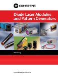
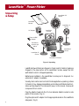
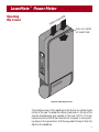
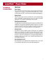
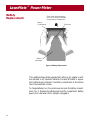
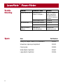
www.catalog.cohr.com
LaserMate™
Power Meter
United States
2303 Lindbergh Street
Auburn, CA 95602
Toll Free: 1-800-343-4912
Tel: 530-889-5365
Fax: 530-889-5366
United Kingdom
15 Greycaine Road
Watford, Herts WD2 4PW
England
Toll Free: 0800 515801
Tel: +44 (0) 1923 206900
Fax: +44 (0) 1923 234220
Germany
Dieselstraße 5b
D-64807
Dieburg
Germany
Tel: +49-6071-968-302
Fax: +49-6071-968-499
France
Domaine Technologique de Saclay
Bâtiment AZUR
4, rue René Razel
91892 Orsay Cedex
France
Tel: +33-1-60 19 40 40
Fax: +33-1-60 19 40 00
Japan
Toyo MK Building
7-2-14 Toyo
Koto-ku
Tokyo 135
Japan
Tel: +81 (0) 3 5635 8680
Fax: +81 (0) 3 5635 8681
User Manual
LaserMate™ Power Meter
User Manual
Part Number 0214-833-00, Rev. B
© 1999 by Coherent, Inc.
LaserMate™ Power Meter
Table of
Contents
General ............................................................................................... 1
Thermal Disk Sensor .................................................................... 2
Features ........................................................................................ 3
Unpacking & Setup ............................................................................ 4
Opening the Cover ............................................................................. 5
Controls & Connections ..................................................................... 6
Front Panel ................................................................................... 6
Range Selection Switch .......................................................... 6
Battery Test ............................................................................ 6
Side Panel ..................................................................................... 7
Power Supply ......................................................................... 7
Analog Output ...................................................................... 7
Meter Response Adjustment .................................................. 7
Detector Socket ..................................................................... 7
Zero Adjustment Control ...................................................... 7
Operation ........................................................................................... 9
Battery Replacement ......................................................................... 10
Specifications .................................................................................... 11
Troubleshooting ................................................................................ 12
Warranty ........................................................................................... 13
Contact Information ......................................................................... 14
LaserMate™ Power Meter
General
4
5
6
7
3
8
2
2
1
9
1
0
3
0
10
LASERMATE
10
BATT
OFF
3
1
.3
X10 FOR
>10 WATTS
Figure 1. LaserMate Power Meter
The LaserMate Power Meter incorporates Coherent’s proven power meter
design and patented thermal sensor technology in an inexpensive, compact package. The LaserMate is available with a choice of five detectors,
to measure laser power from 10 mWatt to 100 watts. The standard LaserMate uses a fast response analog needle. An optional digital display can
be added to combine the tuning capability of an analog with the precision of a digital display.
1
LaserMate™ Power Meter
General
Heat transferred
radially to edge
of disk
Vacuum
Deposited
Thermocouples
Laser
Beam
Figure 2. Coherent Thermal Disk Sensor
Thermal Disk Sensor
Coherent’s patented Thermal Disk Sensor makes LaserMate Power Meters
inherently insensitive to beam position, therefore requiring less setup time
and no critical alignment.
At the heart of the Thermal Disk Sensor is an array of vacuum deposited
thermocouples. Each thermocouple produces a voltage proportional to
its temperature differential.
When the thermocouples are at the same temperature, the sum of the
voltages produced is zero. When the thermal disk is heated by laser energy, heat is transferred radially from the center of the disk to the disk
edge, crating a temperature gradient.
Due to this temperature gradient, voltages are produced by each thermocouple, the sum of which is proportional to the amount of laser power
striking the disk.
The radically symmetrical design of the Thermal Disk Sensor automatically compensates for beam displacement and eliminates the need for critical beam alignment.
2
LaserMate™ Power Meter
General
Features
• Analog meter movement – provides the speed and real time feedback
you need for laser tuning.
• Optional digital back plane – adds the precision of digital readout to
the speed and responsiveness of the analog display.
• Accuracy – The Thermal Disk Sensor provides ±5% accuracy (directly
traceable to N.I.S.T. standard).
• Service – Annual calibration to maintain accuracy and traceability is
available worldwide from service centers in Japan, Germany and the
United States.
• Flexibility – The LaserMate detector heads incorporate the technical
advantages of Coherent’s Thermal Disk Sensor. Because the sensor is
inherently insensitive to beam position, there is no critical alignment,
allowing faster set-up and extremely flexible operation.
• Reliability – The LaserMate is based on the first laser power meter
introduced by Coherent over 25 years ago. There have been more
Coherent Thermal Disk power meters sold than all other brands combined. Coherent meters have a worldwide reputation for accuracy and
dependability under all conditions.
• Portability – The LaserMate Console is compact and light weight,
making it easy to transport and use when space is at a premium.
• Ease of use – The LaserMate Console can be tilted over a wide angle
and has a large meter movement for clear viewing. Range selection,
battery test and zero adjustment are provided by knobs on console.
• Broad wavelength range – The Thermal Disk Sensor provides flat spectral response from 0.3 to 10.6 µm.
• AC/DC operation (with optional battery eliminator).
3
LaserMate™ Power Meter
Unpacking
& Setup
LaserMate 100
Sensor
LaserMate
Manual
LaserMate 10
Sensor
AC Adapter
Phono to BNC
Adapter
LaserMate
Console
LASERMATE
10
BATT
OFF
Screwdriver,
response pot
adjust
3
1
.3
X10 FOR
>10 WATTS
LaserMate 3
Sensor
LaserMate 30
Sensor
LaserMate 20 Sensor
Figure 3. Unpacking
LaserMate Power Meters are shipped in foam inserts. Detector heads are
shipped in the same carton as the LaserMate Console, except the 100
watt detector which is shipped separately.
Batteries are installed in the LaserMate Console prior to shipment. An
optional AC adaptor is available.
Visually check cartons and contents for damage before unpacking. Advise
Coherent of any damage immediately and a Returned Material Authorization will be issued for the instrument (see p. 14 for service). Remove all
components from carton.
Plug the detector head into the 3.5 mm diameter detector socket in side
panel of the console. (Fig. 5)
Plug the optional AC adaptor into the appropriate socket on the LaserMate
side panel. (Fig. 5)
4
LaserMate™ Power Meter
Opening
the Cover
D
SS
E
R
P
E
HER
N
OW
PULL OUT HERE
AT SAME TIME
OUT
RESP
IN
ZERO
Figure 4. Opening the Cover
The protective cover of the LaserMate is held shut by two catches inside
the top of the case. To release the catches, press down on the top of the
case and simultaneously pull outward on the cover. NOTE: This may
require some force the first few times the unit is opened. Continue pulling down on the cover and turn it all the way under the body to form the
stand for the LaserMate.
5
LaserMate™ Power Meter
Controls &
Connections
BATT CHECK
4
3
5
6
2
8
1
1
Low Battery
mark - analog
only version
7
2
9
10
0
BATT 3
0
Low Battery
Indicator
analog/digital
version
LASERMATE
3
10
BATT
1
.3
OFF
Range
Selection &
Battery Test
Switch
X10 FOR
>10 WATTS
Figure 5. LaserMate Console Front Panel
Front Panel
Range Selection Switch
Rotary switch turns meter on and off and selects power range. Positions
for each range are marked on the front panel. For the LaserMate 20, 30
and 100, multiply the range on the panel by 10.
LaserMate
1
Switchable
3
10
20
30
100
150
Switchable
Ranges
(Full scale,
watts)
0.003 0.03
0.3
0.3
3.0
3.0
3.0
3.0
30
0.01
0.1
1.0
1.0
10
10
10
10
100
0.03
0.3
3.0
3.0
30*
30
30
30
300
0.1
1.0
10
100* 100* 100
100
Battery Test
In this position the meter top scale indicates the battery voltage in volts.
Batteries should be replaced when the voltage is below 6.5 volts. (This
level is indicated by the “BATT CHECK” line on the analog only version. On the analog/digital version a “BATT” warning icon is displayed
on the back plane when voltage is < 6.5 volts)
*
Note that although the scale is available on these, the detectors are rated only to 20, 30, and 150
watts CW respectively. Exceeding this maximum will cause damage to the detector.
6
LaserMate™ Power Meter
Controls &
Connections
Side Panel
Power Supply
Plug Coherent’s Auxiliary Power Supply in power supply socket. Use only
Coherent ±9 VDC supply. (Coherent Part Number 4001-0156, 110 VAC
or 4001-0158, 220 VAC). Use of other power supplies may damage unit.
Analog Output
The RCA phono jack connector provides a 0 to 1 volt (nominal) analog
signal (uncalibrated) corresponding with zero to full scale of the meter
movement. It can be used to operate a strip-chart recorder.
Meter Response Adjustment
The response pot can be adjusted using the screwdriver provided with the
LaserMate. This adjustment regulates the speed of response vs. the needle
overshoot (the faster the response, the greater the overshoot). Response is
preset at the factory for the optimal balance for most applications.
Detector Socket
Plug detector head into detector socket on side panel. Any LaserMate
detector can be used with the LaserMate console. Detectors from the older
200 Series Power Meters may also be used with the LaserMate console.
However, in order for the decimal point in the optional digital display to
be placed correctly, the connector on 20, 30 and 100 watt detectors must
be changed at the factory.
Zero Adjustment Control
Zero Adjustment Control adjusts meter movement to zero. This is used
to cancel ambient light level and insure accurate measurements.
7
LaserMate™ Power Meter
Controls &
Connections
Power
Supply
Socket
Analog
Output
Socket
RESP
OUT
IN
Response
Adjustment
Pot
Detector
Socket
ZERO
Zerro
Adjustment
Control
Figure 6. LaserMate Console Side Panel
8
LaserMate™ Power Meter
Operation
5. Place detector
in beam
4
5
6
7
3
8
2
2
1
1
9
0
3
0
10
1. Connect
detector
LASERMATE
10
BATT
OFF
3
1
.3
X10 FOR
>10 WATTS
3. Zero meter
2. Check battery
4. Select scale
Figure 7. LaserMate Operation
To operate the LaserMate Power Meter:
1. Connect the sensor head to the socket on the side panel of the
console.
2. Turn the selector switch to BATT and check that the meter reading is > 6.5 on the upper scale.
3. Zero the meter at the highest range to be measured. NOTE: For
maximum accuracy when using the optional digital display, the
meter must be zeroed at the range being used.
4. Turn the selector switch to the appropriate scale.
5. Place the detector head in front of the beam and read the output
on the meter.
Meter Accuracy – Digital Option
If the analog needle is over range (pegged), the digital reading is not
accurate. The proper range must be selected for accurate analog and
digital readings.
Laser Damage
All sensors will be damaged if the specified maximum power density
is exceeded. Check the maximum power density for your detector
head. Expand the beam if necessary.
9
LaserMate™ Power Meter
Battery
Replacement
Press down and push battery
cover out in direction indicated
to open battery compartment
Battery
Compartment
Press here
Back of
LaserMate
Figure 8. Battery Replacement
The LaserMate Power Meter operates with either an AC adapter or with
two standard 9 volt transistor batteries (Duracell MN1604 or equivalent). Batteries are contained in the battery compartment at the bottom
rear of the LaserMate console.
To change batteries, turn the console over and open the battery compartment (Fig. 7). Replace the batteries and close the compartment. Battery
power is not used when the AC adapter is plugged in.
10
LaserMate™ Power Meter
Specifications
LaserMate Model
1
3
10
20
Spectral Sensitivity
0.25 to 1.5µm
0.25 to 10.6 µm
Meter Ranges
(Full Scale)
0.003, 0.01, 0.3, 1.0, 3.0 0.3, 1.0, 3.0
0.03, 0.1, 0.3, & 10.0 Watts & 10.0 Watts
& 1 Watts
3, 10, 30 &
100 Watts
Response Time
30
100
3, 10, 30 &
100 Watts
150
3, 10, 30 & 3, 10, 30, 100
100 Watts
& 300 Watts
< 1 second
Analog ± 5% of full scale for all powers and wavelengths
Digital ± 5% of reading, ± 2% least significant digits
Accuracy
±7%
Aperture Diameter
0.38"
0.97 cm
0.75"
1.9 cm
0.63"
1.6 cm
0.75"
1.9 cm
0.75"
1.9 cm
0.75"
1.9 cm
0.75"
1.9 cm
Head Diameter
2.75"
6.99 cm
2.5"
6.35 cm
2.5"
6.35 cm
1.99, 2.375"(1)
5.05, 6.03 cm
2.5"
6.35 cm
6.0"
15.24 cm
3.5"
8.89 cm
Active Sensor Area
0.10 in2
0.64 cm2
0.44 in2
2.83 cm2
0.31 in2
2.0 cm2
0.44 in2
2.83 cm2
0.44 in2
2.83 cm2
0.44 in2
2.83 cm2
0.44 in2
2.83 cm2
Max Power Dissipation
1 Watt
3 Watts
10 Watts
20 Watts(2)
100 Watts
150 Watts(3)
2
Max Power Density
Output Signal
200 Wcm
10/100(4)
mV/Watt
2
1300 Wcm2
0.1 mV/Watt
Switchable
0.01/0.001
mV/Watt
(2) Duracell MN1604, 9V or equivalent
≥ 200 Hrs.
Battery Lifetime
AC Operation
(Optional)
200 Wcm (1300 Wcm available)
1 mV/Watt
Battery Operation
30 Watts
2
+9 VDC at Console, 120 VAC 50/60 Hz, 220 VAC 50 Hz
Use Coherent AC Adapter only, for 110 V use PN 4001-0156, for 220 V use PN 4001-0158
1. Head diameter, heatsink mounting plate diameter. 2. Must be mounted on heat sink (customer supplied, 40 sq. in. min.).
3. Intermittent duration (see chart). 4. LaserMate 1: min. power resolution is 50µW; min. detectable power is 300µW.
40
Time (minutes)
30
20
10
0
0
50
100
Power (watts)
150
200
LaseMate 150 Power Duration
11
LaserMate™ Power Meter
Trouble
Shooting
Problem
Probable Cause
Solution
Display does not turn on
Dead battery or AC
Adapter not plugged in
Plug in AC Adapter or
replace batteries with
Duracell MN1604 or
ID 1604 9V batteries or
equivalent
Defective selector switch
Call service
Defective zero adjustment
Call service
Low batteries
Replace
Response pot is
incorrectly adjusted
Adjust pot with
screwdriver provided
Unit does not zero
Needle has excessive
overshoot
Spare
12
Item
Part Number
Analog out adapter, male RCA to female BNC
33-1520
Screwdriver, response pot adjustment
33-1231
Carrying case
33-0555
Small detector head stand
33-1447
Large detector head stand
33-1454
LaserMate™ Power Meter
Warranty
The seller warrants to the original Buyer each item manufactured by it to be
free from defects in material and workmanship for a period of time and under such conditions as specified in the Seller’s warranty for the individual
product, or for twelve (12) months from delivery if a warranty for the individual product is not specified. Major sub-systems manufactured by other
firms but integrated into the Seller’s systems are covered by the original
Manufacturer’s warranty. The Seller’s liability under valid warranty claims is
limited to repair or replacement at the Seller’s plant or the Buyer’s location, all
at the option of the Seller.
THE FOREGOING WARRANTY IS EXCLUSIVE AND IN LIEU OF
ALL OTHER WARRANTIES, WHETHER WRITTEN, ORAL OR IMPLIED AND SHALL BE THE BUYER’S SOLE REMEDY AND THE
SELLER’S SOLE LIABILITY ON CONTRACT OR WARRANTY OR
OTHERWISE FOR THE PRODUCT. THE SELLER’S DISCLAIMS ANY
IMPLIED WARRANTY OR MERCHANTABILITY OR FITNESS FOR
PURPOSE.
All claims under warranty must be made promptly after occurrence of circumstances giving rise thereto, must be received within the applicable warranty period by the Seller, and shall be subject to the terms and conditions
stated herein. Such claims should include the product serial number, the date
of shipment, and a full description of the circumstances giving rise to the
claim. Before any products are returned for repair and/or adjustment, authorization for the Seller for the return and instructions as to how and where
these Products should be shipped must be obtained. Any product returned to
the Seller for examination and/or warranty repair shall be sent prepaid via the
means of transportation indicated as acceptable by the Seller. The Seller reserves the right to reject any warranty claim on any item that has been shipped
by non-acceptable means of transportation. When any product is returned
for examination and inspection, or for any other reason, the Buyer and its
shipping agency shall be responsible for all damage resulting from improper
packing or handling, and for loss in transit, notwithstanding any defect of
non-conformity in the Product. In all cases, the Seller has sole responsibility
for determining the cause and nature of failure, and the Seller’s determination
with regard thereto shall be final.
If it found the Seller’s Product has been returned without cause and is still
serviceable, the Buyer will be notified and the Product returned at the Buyer’s
expense, in addition, a charge for testing and examination may, in the Seller’s
sole discretion, be made on products returned.
13
LaserMate™ Power Meter
Contact
Information
In the event of system malfunction, contact Coherent Auburn Group.
For sales or service information about the LaserMate™ Power Meter,
contact Coherent Auburn Group:
Sales
Service
Fax
(800) 343-4912
(530) 888-5062
(530) 889-5353
Coherent Auburn Group manufactures a full line of laser instrumentation, including the LabMaster Ultima laser measurement system, FieldMaster™ Power/Energy Meter, LaserMate power meters, ModeMaster™
Beam Propagation Analyzer, beam profilers, spectrum analyzers, and single
frequency Helium Neon lasers, as well as LaserPure™ Heat Exchangers,
PolarPure™ Chillers and standard and custom optical components and
assemblies.
You may contact your local representatives or Coherent Auburn Group
for further information regarding these items. Call (800) 343-4912 and
ask for one of our customer care specialists. Purchase orders may be places
by phone, Fax or mail. Where fast delivery is desired, simply contact us at
the number above.
Coherent Auburn Group
United States
2303 Lindbergh Street
Auburn, CA 95603
Toll Free: 1-800-343-4912
Tel: 530-889-5365
Fax: 530-889-5366
Germany
Deiselstraße 5b
D-64807 Dieburg, Germany
Tel: +49-6071-968-302
Fax: +49-6071-968-499
United Kingdom
15 Greycaine Road
Watford, Herts WD2 4PW, England
Toll Free: 0800 515801
Tel: +44 (0) 1923 206900
Fax: +44 (0) 1923 234220
14
France
Domaine Technologique de Saclay
Bâtiment AZUR
4, rue René Razel
91892 Orsay Cedex, France
Tel: +33-1-60 19 40 40
Fax: +33-1-60 19 40 00
Japan
Toyo MK Building
7-2-14 Toyo
Koto-ku
Tokyo 135
Tel: +81 (0) 3 5635 8680
Fax: +81 (0) 3 5635 8681
www.catalog.cohr.com
LaserMate™
Power Meter
United States
2303 Lindbergh Street
Auburn, CA 95602
Toll Free: 1-800-343-4912
Tel: 530-889-5365
Fax: 530-889-5366
United Kingdom
15 Greycaine Road
Watford, Herts WD2 4PW
England
Toll Free: 0800 515801
Tel: +44 (0) 1923 206900
Fax: +44 (0) 1923 234220
Germany
Dieselstraße 5b
D-64807
Dieburg
Germany
Tel: +49-6071-968-302
Fax: +49-6071-968-499
France
Domaine Technologique de Saclay
Bâtiment AZUR
4, rue René Razel
91892 Orsay Cedex
France
Tel: +33-1-60 19 40 40
Fax: +33-1-60 19 40 00
Japan
Toyo MK Building
7-2-14 Toyo
Koto-ku
Tokyo 135
Japan
Tel: +81 (0) 3 5635 8680
Fax: +81 (0) 3 5635 8681
User Manual


![[l] STORAGE](http://vs1.manualzilla.com/store/data/005949981_1-aa131963b29a7cfe7d43fe9de2ac578c-150x150.png)