1
jClamp32 Whole cell voltage
and current clamp
Version 25.5.0
User Manual
Copyright © 2015 SciSoft Co.
(www.SciSoftCo.com)
jClamp32 Whole cell voltage and current clamp 25.5.0 Manual
Table of Contents
jClamp for Windows - Introduction ............................................ 4
Overview .................................................................................................... 4
jClamp Features ........................................................................................ 4
Getting Started ........................................................................................ 19
Supported Hardware ............................................................................. 23
Graphics speed ...................................................................................... 30
File Types ................................................................................................ 33
Update tips ............................................................................................... 35
JC readme utility ..................................................................................... 35
jClamp for Windows - Details ................................................... 37
Data Collection ........................................................................................ 37
StartUp .................................................................................................................................. 37
Menu Bar .............................................................................................................................. 38
Cell Censor ........................................................................................................................... 41
Quick Notes .......................................................................................................................... 46
Stopwatch ............................................................................................................................. 48
Seal ....................................................................................................................................... 48
Telegraph .............................................................................................................................. 49
Chan Watch .......................................................................................................................... 53
CC History ............................................................................................................................ 54
Command Utility ................................................................................................................... 54
MultiClamp IC <-> VC switching ........................................................................................ 65
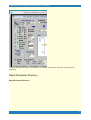
Rapid Parameter Directory ................................................................................................ 72
DAX (Digital-to-Analog eXtra) ........................................................................................... 74
Cm Analysis ......................................................................................................................... 75
Model Cell ............................................................................................................................. 91
Impedance analysis ............................................................................................................. 93
Look32X! .............................................................................................................................. 96
FastLook Video Capture .................................................................................................. 105
Script File ........................................................................................................................... 109
Ini File .................................................................................................................................. 117
Analysis .................................................................................................. 118
Analyze Window ................................................................................................................ 118
IV Plot .................................................................................................................................. 129
File Math ............................................................................................................................. 131
Fitting .................................................................................................................................. 132
VidClip ................................................................................................................................ 135
Data Load Window ........................................................................................................... 136
ABF Search ....................................................................................................................... 137
Episode Math ..................................................................................................................... 138
CC Data Plot ...................................................................................................................... 141
Analysis Script ................................................................................................................... 143
FastLook ................................................................................. 148
overview ................................................................................................. 148
2
jClamp32 Whole cell voltage and current clamp 25.5.0 Manual
Hardware ................................................................................................ 148
main ........................................................................................................ 149
Control .................................................................................................... 151
ViewVDA ................................................................................................. 156
imageJ .................................................................................................... 159
ini ............................................................................................................. 161
Notes on CM calibration ......................................................... 165
Detrending for Cm Analysis ................................................... 167
Index ........................................................................................ 174
3
jClamp32 Whole cell voltage and current clamp 25.5.0 Manual
jClamp for Windows - Introduction
Overview
jClamp for Windows
is a user-friendly whole-cell voltage
clamp data acquisition program which features real time monitoring of cell and voltage clamp
characteristics. The program has no frustrating menu labyrinth. Instead all choices are displayed on each
main window or, in some cases, mouse movements over an area on the window pops up additional
choices. At all times the patch clamper can determine cell status. Data collection is initiated through a
rapid parameter directory (RPD) which maintains a list of 18 parameter filenames or script filenames.
Either a key press or mouse click begins the predefined voltage or current delivery protocols. Scripts are
text files that allow groups of parameter files to be called and run. Most tasks are automated. Some data
analysis is available. However, data is saved in axon binary format (.abf), and can be loaded into
programs like Clampfit and Axoscope (Axon Instruments, CA). Additionally, data can be exported in
ASCII format or via automation to MATLAB Origin, Sigmaplot, and Excel for further analysis. When
the mouse icon is placed over a particular item in a jClamp window, be sure to check for quick
information on that item in the left, lower panel of the main jClamp window.
Copyright © 1996-2015 J. Santos-Sacchi
Last modified: Jan. 1, 2015
jClamp Features
jClamp Features
Copyright 1996-2015
4
jClamp32 Whole cell voltage and current clamp 25.5.0 Manual
jClamp for Windows (v. 25.5.0) is a user-friendly whole-cell voltage
clamp data acquisition program which features real time
monitoring of cell and voltage clamp characteristics. At all times
the patch clamper can determine cell status. Data collection is
initiated through a rapid parameter directory (RPD) which
maintains a list of 18 parameter filenames or script filenames.
Either a key press or mouse click begins the predefined voltage or
current delivery protocols. Scripts are text files which allow
groups of parameter files to be called and run. Most tasks are
automated. Some data analysis is available. In addition,
automation links with MATLAB, Excel, SigmaPlot and Origin are
available.
Attention parents! Get Merlin Programmer for Kids, an absolutely FREE
fun program I wrote to help my kids (now 18) and yours (ages 5-8)
learn how to program within Windows (should work even in Win7) and
hopefully (ultimately) help support their higher education, but more
importantly help them to think logically!
· Nanion Port-o-Patch support is here!
5
jClamp32 Whole cell voltage and current clamp 25.5.0 Manual
New Feature Update
-3/12/15
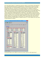
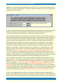
Ability to search ABF files in multiple subdirectories for particular characteristics of the
command protocol or clamp characteristics. Shift right click on displayed file list to copy
list to clipboard, e.g. to paste into Excel. Copy all listed files to a new directory to do
group file analysis, e.g., to analyze all data collected with a particular protocol file.
Double click on a file to plot data in Analysis window.
-1/19/15
Command protocol window shows actual max/min, including 2 sine stimuli. During build, if
magnitude is over board settings then a notification is given. If such a protocol is run a
choice is given to cancel or proceed.
Parameter directory fixed at jClamp diretory subfolder "/param", with subfolders below
automatically entered into search path from RPD and scripts.
Crash detection implemented in jClamp registry key. Logs crashes for debugging
purposes.
·
-12/30/14
·
Automation links remain in effect when exiting Analysis mode. This allows quick reentry to analysis mode rather than checking for connections each time. No need to
double click on the SigmaPlot, Matlab, Excel or Origin icons in Analysis mode. If
programs are available (but need to be set to check for [in in file]) then icons will display
and drag/drop icons to transfer data will be immediately available.
·
In order to use SigmaPlot jClamp templates, available in jClamp SigmaPlot directory,
you must load them into the template.jnt file according to Sigmaplot instructions. You
can add templates for access in jClamp by creating your own in SigmaPlot and putting
the names of the template in the jClamp/SigmaPlot directory (e.g., make a file name
"my_new_template.jnt" in the directory -- it can be an empty file, only the file name is
necessary and must match the template name "my_new_template" in the SigmaPlot
template.jnt file. Check that the new template is available in sigmaplot. It is required
that you reload SigmaPlot to install new templates that are added to template.jnt.
·
Sigmaplot transfers will now increment notebook numbers so that now saving with
new names is not required between jClamp->SigmaPlot transfers. JClamp data file
names are inserted in notebook sections.
6
jClamp32 Whole cell voltage and current clamp 25.5.0 Manual
·
All transfers of data to other program via automation will leave the automation
program files open after jClamp closes. You can continue work on the data in those
programs (SigmaPlot, Matlab, Excel or Origin) and save what you like. Matlab will ask
before closing, Xcel will ask to save data before closing. SigmaPlot will not close.
Origin?
·
Selection of DD1550 board sets clock increment to 2 us because that is required by
MD. There is still a jitter that I detect that MD cannot recapitulate. I think it is present
not just in jClamp but also in Clampex. I will fix when they acknowledge and fix. In order
to use MD (Axon) boards you will need to copy some files to the jClamp32 directory.
The required files change, so email me for information.
·
FFT and PSD analysis bugs fixed.
·
A Matlab script to do PSD analysis on jClamp files can be provided.
·
-12/15/14
·
JClamp now supports Molecular Devices DigiData 1550 (there is an intermittent one
point jitter in their driver so that high frequency Cm measures are not stable).
Molecular Devices (MD) is working to fix the jitter, and I will update when this
happens. Lower frequency Cm measures are less susceptible to the jitter. Update (SEE
ABOVE): MD has just released a new version of pClamp (v.10.5.0.9) which apparently
fixes the jitter issue in pClamp (Clampex). However, clock rates are limited to multiples
of 2us. Thus, older versions of Clampex collected data that had the potential for
inaccurate timing when using the 1550. jClamp does not currenly support the 2us
increment limitataion on sampling, and, in any case, the new drivers still produce jitter in
jClamp even at 2us sampling. I'm trying to figure this out. Unfortunately, I do not
recommed using the 1550 with jClamp at this time.
·
MultiClamp Commander Telegraphs are now supported internal to jClamp – no need
to run jc_Client applications anymore. Set MultiClamp on in ini file History tab. Provide
paths to MultiClamp servers (MC700.exe and MC700B.exe) in the ini file and select
the associated check box to run automatically. Only one Multiclamp (700A or 700B is
supported).
·
Multiclamp mode can automatically be controlled by digital out 3 in a protocol file.
Multiclamp Commander must be set to “ext” control. This means that voltage clamp
and current clamp can be switched real time within partitions of a command episode
(protocol command type must be set to voltage clamp). Only channel 0 in/out command
7
jClamp32 Whole cell voltage and current clamp 25.5.0 Manual
protocol should be used. Other channel inputs can be sampled as usual.
·
Drop down box in Data Load Window allows quick selections of previously viewed
data directories.
·
Previously channel protocol holding potentials were set prior to running the protocol
(500 ms plus a computer dependent variable time preceded the protocol command). This
eliminated a transient in the protocol response if the CC holding potential were
different. Since you should be aware of mismatch in CC hold and protocol hold, this
feature is now removed. Now, you will see a transient current response at the onset if
CC hold and protocol hold do not agree. You must make sure that CC holding potentials
are the same as the protocol holding potentials for all channels that are active.
·
Prior Update:
·
Midnight issue fixed. At midnight a new directory will be made for data collections. If
CC save is on it will turn off and restart for saving in new directory.
·
Inter-episode times are now saved with data file. View by moving mouse cursor over
inter episode time in command protocol window in Analysis mode.
·
Prior Update:
·
Sister parameter files - individual files can be linked to follow each other (simple
alternative to script files). For example, jclamp.prm, test.prm, test1.prm, and test2.prm
can be run sequentially by renaming first file to jclamp[test.test1.test2].prm.
·
New box in Parameter load window lists files by date or by today's use. This
supplements typing names which lists by matching.
·
ABF fileload window info reports if math model was used. If Matlab model was used
script is appended to abf file and then shift right click on filename opens script file in
text box.
·
Cm calibration file is correctly listed when mouse is over calibration button in Analysis
window. The file has always been appended to abf files for Cm corrections.
8
jClamp32 Whole cell voltage and current clamp 25.5.0 Manual
·
Works in Win 8. Set run as administrator in shortcut.
·
And, of course, bug fixes.
·
Full installation to use 7Zip compression for quickie updates. Bugs fixed as well.
·
Updated MD in-cell stray capacitance compensation with software assistance,
including automatic compensation – see Cm Analysis in Help file.
·
Digital trigger now has minimal delay between triggering and data collection, except
for protocols with P/N, prepulse or CC inter use.
·
Cs stray capacitance compensation prior to cell pop-in disabled. Replaced by robust
in-cell stray capacitance compensation using MD (multi-dual) sinusoidal stimulation
(see help file).
·
Molecular Devices releases new Axoscope (pClamp) 10.3.1.4 with new DLL to fix
spurious voltage output, and allow digital output during 4 DAC output. jClamp v22.7.0
and above uses this fix.
·
Support for the Tecella Pico USB patch clamp amplifier (www.tecella.com). Up to four
units running simultaneously.
·
Support for 4 DAC outputs for those boards that have four DACS, including the Axon
DigiData 1440A, IOTech Personal Daq, and soon the CED Power.
·
The previous full version was the last one that supports only 2 DAC channels.
Future versions (coming soon) will support 4 DAC outputs for those boards that have
four DACS, including the Axon DigiData 1440A, IOTech Personal Daq, and CED
Power.
·
jClamp will now automatically startup with the last ini file selected in the Identity
window. An edited shortcut will override last selection if different. Remember, to make
an edited shortcut linking directly to your ini file, edit a newly created shortcut Target
property by placing your ini file (e.g., my_ini_file.ini) at the end of the target command
with a space in between the two. To access the properties of a desktop shortcut, right
click and select properties.
9
jClamp32 Whole cell voltage and current clamp 25.5.0 Manual
·
Support for both Axon Multiclamp 700A and 700B telegraphs. Previous version only
supported the 700B. See the jClamp help file under Telegraph.
·
Support for new board, NI USB X Series. Amazing! 1 megaHz 16 bit sampling on all 8
channels without multiplexing. Synchronous digital output. About $3K. Could not ask
for more. The new NI-DAQmx 9.3 drivers need to be installed. Visit NI at http://
joule.ni.com/nidu/cds/view/p/id/2337/lang/en.
·
User info (License owner, board, operating system, disk size and memory) collected
when check for updates occurs. Useful for me to identify user issues and aid in
debugging.
·
Automatic or manual check for new version of jClamp on the web – set choice in ini
file under Script Tab.
·
Impedance analysis with Nyquist/Bode Plots and model fitting
·
Additional script commands to control CC window parameters
jClamp Features
·
Vista and Win7 users must disable User Control Account in Users Dialogue!
·
In-cell stray capacitance compensation for Cm measures.
·
Digital flip-flop overrides partition digital out in command protocol.
·
Look32X! video capture with cameras and devices with DirectShow or VFW drivers.
Synchronized video capture with electrophysiological data (as best as Windows will
allow! TIFF and other image file support.).
·
FastLook! -- Andor (www.andor.com) camera support and Prosilica Gige
(www.prosilica.com) vision camera support. Link video frame capture to patch clamp
data collection. Synchronized data for each frame. Export automatically to ImageJ for
video analysis. Combined with jClamp or standalone program available.
10
jClamp32 Whole cell voltage and current clamp 25.5.0 Manual
·
CellSeeker and MagicSeal coming soon!
·
Automatic offset current cancellation
·
User control over audio feedback during seal formation.
·
Enhanced P/N subtraction.
·
Switch polarity for whole cell or inverted patch in CC window.
·
Disable dual patch mode in CC for stimulation with channel 0 or 1 D/A while
recording from channel 0
·
Removal of stray capacitance effects on calibration and during cell recording for Cm
analysis
·
Plots of Real and Imaginary components of raw currents
·
Simple way to set angle of dRs/dY-90 or angle of dC/dY in Phase detector Admitance
Window, and angle will be used by single sine protocol to get Magnitude at 0 and 90
degree phase for C and R analysis. Note that using Rs compensation (or an Rs dither)
and C compensation (or a C dither) for dithering is a poor method for dithering actual
Rm and Cm if Rm is not much greater than Rs, or if Rm or Cm changes substantially
during your experimental measurements -- the limitations of single sine analysis
·
Non-harmoninc two sine stimuli to avoid nonlinear distortion interference with Cm
measures.
·
Free support for the Axon 1200A and B boards that Axon no longer supports with
their new software! See supported hardware for more information.
·
Support for the IOtech PersonalDaq. It is a great board (~ $1,400) with many
capabilities, close to the Axon 1440 series.
·
Detached Telegraph window with only the enabled channels (from 1-4 for each of the
11
jClamp32 Whole cell voltage and current clamp 25.5.0 Manual
two supported amplifiers) displayed.
·
Vista and Win7 support
·
Detached PDF Help file in addtion to Windows Help file. You can search and print out
the help file.
·
Separate Audio program (jc_audio.exe) for recording/playing MS wav audio files,
which can be played during script execution now, since Windows Vista does not include
one.
·
Multiple instances of jClamp can be run, each controlling a different A/D D/A board!
Or use another instance to analyze data while the first instance is actively collecting
data.
·
Frequency analysis can successfully monitor bilayer prep capacitance, making
jClamp a good choice for these types of studies
·
Cell Censor window provides full cell parameter analysis either in Time or Frequency
domain
· Axon Multiclamp telegraph support.
· User selectable channel input for telegraphs.
· Real time, scalable plotting of Cm or Im vs time or voltage collected with protocols.
· Support for Axon 1440 series!
· Support for National Instruments M series boards. NI 6251-USB and NI PCI-6221, in
particular.
· NI boards that use Ni-daqmx driver (M series and also the PCI-6052E) and Axon's 1320
and 1440 series now can have dual analog output and up to 8 input channels.
12
jClamp32 Whole cell voltage and current clamp 25.5.0 Manual
· The NI PCI-6221 board is used by Neobiosystems to control their ( PatchMAX 100A )
and jClamp will work with their system to provide user friendly patch clamp and two
electrode voltage clamp solutions.
· User choice of Dual frequency Cm calulation from f1, f2, or aveage of both.
· Phase Sensitive Detector (PSD) exposed for phase analysis.
· Automatic fusion event analysis.
· Easy capacitance measures – new method based on actual angle of dY/dCm – perfect at
last!!.
· Average after all episodes are run or average each episode before continuing to the next
episode..
· Smart averaging – only average as many runs as required to reach a desired signal to
noise ratio!.
· More flexible delivery of frequency stimuli.
· Axon 1322A support.
· Storage view in Analysis mode – view two data file plots simultaneously (previously
opened and current) .
· Independent analysis and data collection CM calibrations file loading.
· Streamlined generation of command protocols from ABF data files .
· User choice of detrending of raw data prior to CM analysis (Technical Note released) .
· NI PCI-MIO-16E-1, NI PCI-MIO-16E-4 support.
13
jClamp32 Whole cell voltage and current clamp 25.5.0 Manual
· Fitting with user supplied equations.
· Now measure capacitance with either 2-Sine analysis or Phase tracking.
· Very detailed information for all files in data directory in data load window when info
button is pressed.
· IV plot window calculates reversal potential, and slope resistance; multiple I-v plots for
comparison.
· Quick notes window allows button click insertion of pre assembled, often used notes into
the log file.
· Conditional scripting with parameters from Cell Censor. For example, wait for membrane
resistance to reach a certain value before running a protocol.
· DCM files are only saved when enabled in ini file under History tab.
· CED Power 1401 support. Four DAC outputs; control four patch clamp amplifiers.
Channel watch channels moved from 2-5 to 4-7 for all boards. Shell out (from Data Load
window) to Adobe Acrobat or reader to look at lab notebooks. I suggest that you scan in
your hand written notebooks as an image and place a PDF conversion into each day's
data directory for viewing. NT and 2000 support for Labmaster DMA and Daqp 308
boards. jClamp for the old Labmaster DMA board is FREE!!! No license needed. Great
for student labs!!!! Break out those old boards and put them in some new, fast and
cheap computers.
· Multiple stopwatches.
· Streaming video capture and playback; record video during data collections; control
through script or via Look! video window. Screen shots available from scripts.
· CM calibration changed to provide more resolutions. accalib.prm and accalibi.prm are
revised. Please recalibrate to use extra resolutions. Remember to check proper function
with electrical model!!!!!
14
jClamp32 Whole cell voltage and current clamp 25.5.0 Manual
· Channel watch is functional (if enabled) even when CC is not running.
· Conditional scripting. Continue scripting after switch from/to current/voltage mode or
based on values obtained from analog Channel Watch (e.g. based on temperature
change reading).
· Ability to transfer voltage clamp holding current to current clamp upon mode switch. Also,
current clamp membrane potential to voltage clamp.
· Ability to set all partition start voltages/currents to holding level in Command Build
Utility. Useful when passing hold from Cell Censor to protocol.
· Better memory management in Win 98. IniEditor can now be opened from within jClamp
without "out of memory" error. Tested with 128 Meg memory system.
· Automation link with SigmaPlot 2000, Excel 9, MATLAB 5.3 and Origin 6. Rapid data
transfer and plot generation. May work with some earlier versions. Enable use for each
program seperately in jclamp ini file. Scripting of application commands in jClamp
analysis scripts.
· Two sine FFT based CM tracking now supported under current clamp.
· Ability to use data file (abf) traces as commands in Command Build utility. Automatic
generation of command parameter files from abf data files. For example, immediately
stimulate cells in current clamp with currents obtained under voltage clamp. Also, FFT
can now be computed on any portion of data trace with automatic zero padding.
· Support for the National Instruments PCI-MIO-16EX-10 (10 usec) and PCI-6052E (3
usec) boards, 16 bit A/D, D/A-- boards with breakout about $2K.
· Support for the IOtech daq2000 PCI board. 16 bit A/D, D/A @ 100kHz -- board is $500!
Cabling and breakout extra. Important -- contact me before getting one (there is a glitch
on analog out).
· High time and magnitude resolution capacitance measures during episodic protocols!
Measure capacitance, Rs, Rm simultaneous with your favorite step, ramp or AC
protocols. Automatic analysis. Episode length up to 1 million pts for Axon boards and
15
jClamp32 Whole cell voltage and current clamp 25.5.0 Manual
IOtech daq2000 -- measure voltage induced capacitance changes up to 10 seconds per
episode (@ 10 us clock)! 10 million pts for National Instruments boards!
· Real time monitoring of cell and clamp characteristics in Cell Censor Window. Full
control over two patch clamps. Channel 0/0 [A/D- D/A ](patch clamp #1), channel 1/1 [A/
D - D/A] (patch clamp #2), both channels or junctional coupling possible. Pseudosimultaneous measures under current and voltage clamp on channel 0 and 1 in Cell
Censor. Automatic pulse polarity flip-flop for charge buildup control.
· Four additional channels can sample peripherals (e.g., pressure monitor) at user selected
rates
· Works with either the DigiData 1200, 1200A or 1320 series boards from Axon
Instruments, Labmaster DMA, IOtech daq2000, National Instruments PCI-MIO-16EX10 and PCI-6052E boards or Quatech DAQP-308 PCMCIA -- have Lap can Clamp!
· I suggest a Hauppauge video capture card - you can get them without the TV tuner for
less than $100.
·
Convert digital outputs to analog outputs with the optional DAX (D/A eXtra)
hardware add-on. Control up to four more amplifiers. Monitor seal formation, set
holding potentials, monitors cell characteristics, synchronous episodic delivery.
·
Four channel graphical history display of selectable cell and clamp characteristics time window user adjustable.
·
·
·
·
Graphically view seal formation with frequency varying audio cues.
Customizable initialization settings for individual users - including graphic ID in Cell
Censor window. Separate initialization file editor.
Automatic data directory naming, file naming and saving.
Powerful graphical voltage/current protocol build utility. Episode length up to 10
million for National Instruments boards, 1 million pts for Axon boards and IOtech
daq2000, 128k pts for Labmaster and DAQP-308. Step, ramp and AC stimuli (one, two
or three sine; chirp). Dual command protocols support simultaneous current and/or
16
jClamp32 Whole cell voltage and current clamp 25.5.0 Manual
voltage clamp. Gap free collection is supported. Full command waveform scaleable
based on user scale factor set in INI file. For example, with a button press increase or
decrease the wave form magnitude by a factor of 2 about the holding level. Additionally,
toggleable timing increments by a factor of 2. Automatic saving of individual runs during
averaging.
·
Protocols can be run at the press of a key or click of a button. External file based
user stimulus incorporation. Arbitrary number of input channels and order of input
channels in parameter files. Analog output is through channel 0 or channel 1, or both
simultaneously. Each parameter file contains information for separate and distinct
command waveforms for each output channel. Random episode delivery; auto
supplemental A/D gain (1-8X) {Axon 1200, DAQP-308 and daq2000 boards}; dual
telegraph inputs to control gain and clamp type, and monitor capacitance and filter
frequency.
·
Digital output during, before, after or synchronous (depends on board) with analog
output.
·
TTL or key triggerable starts - full run or individual episodes.
·
Text, audio and video (time lapse grabs, or linked to data collections[after each
average, or episode]) clips can be saved, and easily retrieved and played during
analysis. Any Windows compatible cards with wav audio drivers and video for Windows
drivers will work.
·
Script files can run individual protocols or loops can be programmed; wait periods are
allowed between protocols and during these periods cell and clamp characteristics are
continuously monitored and saved to disk. Control holding potentials (main board and
DAX); output serial port commands, e.g. to control external hardware [GPIB under
construction]; set digital out ports; trigger video capture or time lapse capture.
·
Scripts can be automatically canceled if one or more particular cell or clamp
characteristic crosses a predefined threshold; e.g., if resting membrane resistance (Rm)
drops below 50 Mohm or if electrode resistance rises higher than 40 Mohm.
·
Analysis features are smooth and graphical. Axes or scale bars. User text on plot.
Episode math, file math, fitting of exponentials, Boltzmanns, FFT. Residual series
resistance correction, cursor based analysis, IV plots, togglable leakage subtraction
(view raw or subtracted traces), x-axis data shifts. Exporting of data to abf, atf, ascii, or
matlab. Copy plots to clipboard for paste in word processors. Trace comparator 17
jClamp32 Whole cell voltage and current clamp 25.5.0 Manual
combine traces from Analysis window into new window for comparison across files.
·
Data file loading is enhanced by the ability to view key items in the file before
loading; e.g. data owner, cell and clamp characteristics immediately prior to data
collection, parameter file name, sampling clock, number of channels etc.
·
All data collected can be summarized in printed form. Each protocol and associated
data traces are printed along with key protocol parameter information - four data files
per page. All cell and clamp characteristics for each cell studied are plotted versus time.
·
Data files can be selected by parameter filename and printed or plotted on screen
(plots have selectable interplot periods and a pause feature).
·
Each data file has appended the parameter file in ASCII format, allowing the display
of all information in the build utility during data loading. Key ASCII information can be
searched for and files save to a new directory for group analysis.
·
Logging implemented. Recall and play (abf, cc, cm, not [audio, video, text, cc clip] )
files from log window with button click. Search logs for information. Show all logs on
disk. Edit them. Log is run from Main menu bar in jClamp (when in Analysis mode), or
can be run as an independent program (jc_log.exe).
·
Capacitance tracking allows monitoring of cell characteristics using two sine FFT
based analysis with analog and/or digital stimulation (prepulse, incrementing pulse,
ramp) at 2.5 or 5ms resolution and noise of 10fF (model cell with 200 MHz Pentium).
Additionally, capacitance, Rs, Rm can be measured simultaneously with your favorite
step, ramp or AC protocols. Automatic analysis. Very powerful feature!
·
Analysis scripts. (under construction)
·
Binary save of Cell Censor and CM tracking data files. Faster save and load, and
smaller size. Ability to save in ASCII format set in INI file.
·
"Screen Shots" to save jClamp window arrangements for instant retrieval;
Collapsible Cell Censor window. Sizable plotting window during data collection (drag to
size). Unobtrusive RPD window, updated searchable help file (including help on the new
features). Screen shots can be loaded at the command line in a shortcut -- "jClamp.exe
myinifile.ini collect.scn" will bypass the Identity login form and load the saved sreen
18
jClamp32 Whole cell voltage and current clamp 25.5.0 Manual
format.
Getting Started
Getting started
If you buy jclamp you will need to register. After you install and run jClamp on the computer you want to
use, press the registration button after running jClamp. Press the copy info button and paste all the info
into an email to me. It looks like this :
---------------------------------------------------------------------------------------------To: SciSoft Co.
[email protected]
http://www.SciSoftCo.com
Date: 03/17/07
Time: 10:55:24
Application: jClamp32.exe
Version: v. 17.0.0
System: Windows NT 5.1 (Build 2600)
Application path: C:\jClamp32
Registration code: [A40079BD 22585A 26A3654 10196A30 5E72F78]
---------------------------------------------------------------------------------------------I will send you the hardware license file for jClamp or a link to download it. Alternatively, you can use the
fulldemo license on the web for a month to check out the program with hardware, or you can use the built
in math model to test the program.
Your hardware license is named <your_name.lic>. It may be zipped and named <your_name.zip>, and
unzipping will extract the license file <your_name.lic>. Download and save the file. Do not open it – it is
simply an encrypted text file. The file is necessary for jClamp to work with A/D-D/A hardware. Make a
backup copy.
You should have installed jClamp into the default directory <C:\program files\jclamp32\>.
In that directory there is a default software only license named <jclamp32.lic>. You should rename that
to <jclamp32_soft.lic>, copy your license file into the jClamp32 directory, and rename it
<jClamp32.lic>. It should not be write protected.
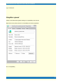
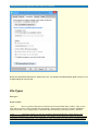
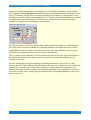
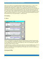
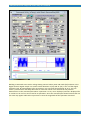
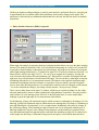
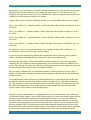
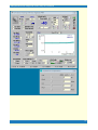
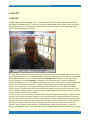
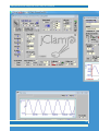
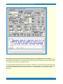
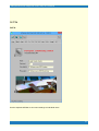
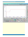
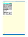
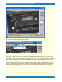
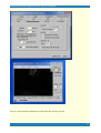
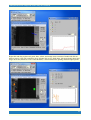
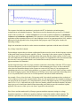
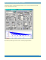
When you run jClamp you should be able to turn off model mode (in the ini file on startup, or in the pop
up under the user graphic – see image below) to access hardware. You must make and load an ini file to
access your hardware. See help file (accessible from Windows Start button or About button in menu bar
in jClamp [opens on extreme left mouse movement] – see second image below) for further info on getting
started.
19
jClamp32 Whole cell voltage and current clamp 25.5.0 Manual
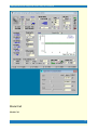
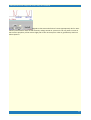
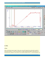
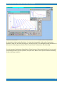
-------------------------------------There is a new method for communicating with a jClamper during experiments without interference during
20
jClamp32 Whole cell voltage and current clamp 25.5.0 Manual
recording. A text file named "jcreadme.txt" can be placed in the jClamp32 directory at any time, e.g.,
remotely via network. This note will pop up at the start of jClamp or, if jClamp is running, when the Cell
Censor is turned off. The note can be printed prior to exiting the window. Upon exiting, the file is deleted,
but the information is stored in the file "jcreadme.bak".
Additionally, if a text message is present, the audio file named <jcreadme.wav> located in the jClamp
<sounds> directory will be played. You can record your own audio message (using Windows sound
recorder, for example) along with the text message or just play a notification sound when the text
message opens. Just rename your recorded wav file to <jcreadme.wav> and place in the <sounds>
directory. In the <sounds> directory there is a file <no_sound.wav> that can be copied and renamed to
<jcreadme.wav> and/ or <giga.wav> so that no sound is played during the execution of these files within
jClamp. jClamp now has a stand alone version of <jc_audio.exe> which can be used to record or play
wav audio files, since Windows Vista does not have a sound recorder that does this. It is accessible in
the jClamp directory or the jClamp start menu.
Using the jcreadme feature is a good way to remind yourself or another jClamper of something
important!
When you restart jClamp the second time Windows will attempt to re-configure jClamp. This normal and
should only happen once.”
--------------------------------------
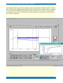
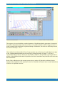
Because the computer may crash if jclamp is run with the ini file set to a board that does not
exist in the computer, the default jclamp.ini file is initially set to run in a built-in math model
mode. To run with hardware, you should first set the board type and address, then disable
model in the ini file under the
gain tab, or
uncheck the model checkbox while jclamp is running.
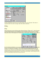
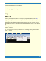
Anytime you make changes to the ini file you must save the file and restart jClamp, or press
the <re-ini> button on the Bar Menu. It is probably better to restart jClamp. The settings open
in a pop-up window when you move the mouse over the graphic (default is a spiral ganglion cell
– replace that graphic with a picture of individual jclamp users – set in ini file) in the upper left
region of the Cell Censor window.
21
jClamp32 Whole cell voltage and current clamp 25.5.0 Manual
You must make sure all paths in the ini file match your machine's paths. For example, in the ini
file default the directories are C:/program file/ jclamp32 but yours may be different. Make sure
everything is set right in the ini file, and then save it as a different name -- like
"your_name.ini". You can specify your ini file rather than the default jclamp32.ini by doing the
following. <"C:\Program Files\jclamp32\JCLAMP32.EXE" my_ini_file.ini >.
If you find that the file <scrrun.dll> is giving problems, then it may be necessary to register it. Run the
following on the command line
"REGSVR32.EXE C:\WINNT\system32\scrrun.dll"
Make sure your windows directories are correct. For win98, it may be "windows/system/".
You must disable User Account Control in Vista and Windows 7.
In Windows Vista, you may need to actually unregister some files that jClamp installs. This is a
very strange bug for Vista! A batch file named <vista_unreg.bat> will be in the jclamp
directory, and you should only need to double click on it. You may look at the contents with a
text editor like notepad.
If you are using an old Labmaster DMA board then jClamp is useable without a license. Remember the
free license is only available when the ini file is set to use the Labmaster board (under gain tab). Set the
proper Port address! The Labmaster board is controlled exclusively through Port I/O with the jClamp
VXD or SYS driver. The only differences with the hardware setup required by pClamp is that the ports
A0-A7 should all be configured for output. A7 is scope trigger. See the hardware manual. B0 is trigger
input. C channels are not used. Cm tracking and gap-free are functional only in Win 95/98, although 2sine command protocols are supported. Win 2000 performance is superior. Normally, if there is no
hardware license the registration window will appear, indicating that the license is software only or that so
many days are left in the hardware fulldemo license. For the free labmaster support, there is no license, so
the register window will open. If you want to bypass that window you may create a shortcut on the
Windows desktop to jclamp32.exe, as you would do for any other program. In the properties window,
target line, you should append the word "skip_reg". For example, <"C:\Program Files\jclamp32
\JCLAMP32.EXE" skip_reg> is taken from the target line of a shortcut. It will run jclamp but not display
the registration window. You could also specify a particular ini file other than the default jclamp32.ini by
doing the following. <"C:\Program Files\jclamp32\JCLAMP32.EXE" my_ini_file.ini skip_reg>. Note
there is a space after the executable name and between the ini filename and "skip_reg".
Gain setup in ini file
First check that the output is working.
Set the gain for DA to 0.001 in the textbox. Save the ini file. Restart jClamp or reinitialize. Set Vpulse to
zero. Set the cc hold to 1000 mV and the meter connected to your output channel should read close to
that. Verify that the output corresponds to changes in cc hold.
22
jClamp32 Whole cell voltage and current clamp 25.5.0 Manual
Now set the DA gain to that required for your amplifier. For example if you need 10 times the voltage set
the gain to 0.01. Save the ini file. Restart jClamp or reinitialize. Verify that the output corresponds to 10
times the changes in cc hold.
Now that the DA is set correctly, you can set the AD scale. Remember to always set the DA scale first.
Use a model cell to check everything before doing real experiments!
Supported Hardware
Supported Hardware
The program is written to work with the Tecella Pico patch clamp (issues remain, however -- see
below), Power 1401 from CED, 1200, 1200A, 1320, 1440 and 1550 series boards from Axon
Instruments (Molecular Devices), the Labmaster DMA from Scientific Solutions, the DAQP-308
PCMCIA card from Quatech, the IOtech daq2000/XP Pro PCI board, the IOTech Personal daq 3000
(2 or 4 DAC) and the National Instruments E series PCI-MIO-16XE-10, PCI-6052E, PCI-MIO-16E1, and PCI-MIO-16E-4 boards, and M series USB 6251. NI PCI-6035E and PCI-6024E boards are
supported in a limited way (see below).
jClamp also supports video capture using a Video for Windows compatible board - see the Look32X!
section. Streaming video capture and playback; record video during data collections; control through
script or via Look! video window. Check script command section and check menu on the Look!
window. I suggest a Hauppauge video (see www.hauppauge.com) capture card - WinTV PCI - you can
get them without the TV tuner for less than $100. The default capture driver is number 0, but now you
can provide other numbers in the jClamp ini file under the "misc" tab. Setting the driver number to 999
causes jClamp to skip the check for a board, and no capture will be available.
CAVEAT: if you have different board types, protocols created with one board selected may not
be the same if you use them with another board. This is because specifications, e.g., minimum
clock, synchronous digital output, voltage out, can be different. You should set the board type
to the board that was used to save the data when viewing the data. You don’t need the board
present, but can work in math model mode. Actually, I have tried to make the aforementioned
not a requirement. For example, the board type is saved with a data file and I use it to select
the board type when analysis mode is in effect, so that data files are matched for board
characteristics. In the command utility the board that made the protocol is now exposed, and
23
jClamp32 Whole cell voltage and current clamp 25.5.0 Manual
when loading data files the board that was used is exposed in the window. Nevertheless, it is
safest to select the board on startup to look at data generated with a particular board!
Gain setup in ini file
First check that the output is working.
Set the gain for D/A to 0.001 in the textbox. Save the ini file. Restart jClamp or reinitialize. Set
Vpulse to zero. Set the cc hold to 1000 mV and the meter connected to your output channel should
read close to that. Verify that the output corresponds to changes in cc hold.
3. Now set the D/A gain to that required for your amplifier. For example if you need 10 times the
voltage set the gain to 0.01. Save the ini file. Restart jClamp or reinitialize. Verify that the output
corresponds to 10 times the changes in cc hold.
4. Now that the D/A is set correctly, you can set the A/D scale. Remember to always set the D/A scale
first.
1.
2.
24
jClamp32 Whole cell voltage and current clamp 25.5.0 Manual
-------------------------------------------------------------------------------------------------------------------------------------------
The configuration settings must be set correctly for each AD board.
CED boards
The Power 1401 from CED (16bit in/out) works in WIndows 95/98.NT/2000/XP Pro. Follow the setup
described by CED. Digital in 0 (Event Input 0) is used for triggering -- pulse to low for trigger. Trigger
BNC is not used. Digital out 0 (hi byte 0) on front panel is scope trigger. Other digital outs are low byte
on expansion connector. Fastest clock supported is 3 usec for synchronous in/out. CED command files
must be placed in the jclamp32\CED\ directory. They are ADCMEM, MEMDAC and MEMDAD.
Analog output on channel 2 and 3 is controlled with DAX window. CC monitoring for a 3rd and 4th
25
jClamp32 Whole cell voltage and current clamp 25.5.0 Manual
amplifier uses channels 2/2 and 3/3 in/out. Synchronous digital out issupported . Other models may be
supported.
Axon A/D D/A boards
The 1200A (12 bit in/out) and 1320/1440 series (16 bit in/out) boards are useable in WIndows 95,98,
NT4, 2000/XP Pro. Follow the setup described by Axon. For both boards, digital in 0 is used for
triggering -- pulse to high for trigger. Start trigger is not used because it is not directly accessible to third
party software, except for the 1440 series (in this case, start BNC is used to collect data). Digital out 7 is
scope trigger out. The 1200 Axon boards are configured by supplied Axon software (e.g., Axoscope),
and the axdd1200.ini file located in the Windows (Win 95 & Win 98) directory is used by jClamp. If
there are problems, check the hardware address, interrupts, and DMA channels in Axoscope. Get that to
work! The 1200 board may be functional only in Win 95/98.
Unlike the other boards, the 1320 series boards treat the synchronous digital output as another channel;
therefore when using these boards the clock will change in the command utility when synchronous digital
output is enabled. The 1440 series supports synchronous digital output and multiplexing is not used, so
clock remains the same regardless of input channel number.
The DD1550 board is supported but sets clock increment to 2 us because that is required by Molecular
Devices. There is still a jitter that I detect that MD cannot recapitulate. I think it is present not just in
jClamp but also in Clampex. I will fix when they acknowledge and fix.
Under NT or Win2000/XP Pro, the 1200A board does not work well with jClamp -- the drivers
supplied by Axon (from SSI) are dysfunctional. Cm tracking does not work, but the 2-sine command
protocol it works.
The drivers for all Axon boards are installed with the manufacturer's software program Axoscope. See
the instructions supplied with the boards. Get Axoscope to work!
For the 1320 series (1320A, 1321A, 1322A), Axoscope version 9 (or above - but see their website to
make sure which Axoscope to use!) must be installed, since the new drivers that are released with this
version are used by jClamp versions greater than 10.9.0. The boards should be occasionally
calibrated with the Axon software Axoscope – see the Axon documentation. jClamp uses the
board’s hardware stored calibration data. The file <AxDD132x.dll, ver. 1.1.0.7> found within the
Axoscope 9 directory must be copied into the jclamp32 directory for the board to work with jClamp.
For the 1440 series, AxDD1440.dll must be copied into the jclamp32 directory. However, if you have a
new Axoscope version that works get the files from that version's directory (see below)
In order to use MD (Axon) boards you will need to copy some files to the jClamp32 directory. You
must get Axoscope to work with their boards before running jClamp. If Axoscope identifies the boards
then jClamp will work.
1322 boards:
AxDD132x.dll
1440 boards:
26
jClamp32 Whole cell voltage and current clamp 25.5.0 Manual
AxDD1400.dll
wdapi1140.dll
wdapi1011.dll (?)
1550 boards:
AxDD1550.dll
DD1550fpga.bin
wdapi1140.dll (?)
wdapi1011.dll (?)
You may want to copy all regardless of board you have. The the required files may change so email me
for information.
The software version of the Axon Multiclamp Telegraph system is supported – see telegraphs.
Labmaster and Axon 1200 boards
jClamp for the Labmaster DMA and for the Axon 1200A and B boards is free -- no license required.
However, it is not sure whether they will work with the newest versions of jClamp since I don't have the
boards anymore to check.
The Labmaster (12 bit in/out) must have the Port address set correctly in the jClamp ini file.
Remember the free license is only available when the ini file is set to use the Labmaster board or
axdd1200 board (under gain tab). Set the proper address for the Labmaster! The Labmaster board is
controlled exclusively through Port I/O witht the jClamp VXD or SYS driver. The only differences with
the hardware setup required by pClamp is that the ports A0-A7 should all be configured for output. A7
is scope trigger. See the hardware manusal. B0 is trigger input. C channels are not used. Cm tracking and
gap-free are functional only in Win 95/98, althought 2-sine command protocols are supported. Win
2000/XP Pro performance is superior. The Axon 1200 board needs the DriverLinx installation (NT
version for Win2000 and above). Axon supplies the drivers. Email me if you have a problem getting
them. Axoscope 9.2 is the last version of Axoscope to support the board, so you must use that program
to verify that everything is working before using jClamp. Normally, if there is no hardware license the
registration window will appear, indicating that the license is software only or that so many days are left in
the hardware fulldemo license. For the free labmaster or Axon 1220 support, there is no license, so the
register window will open. If you want to bypass that window you may create a shortcut on the Windows
desktop to jclamp32.exe, as you would do for any other program. In the properties window, target line,
you should append the word "skip_reg". For example, <"C:\Program Files\jclamp32\JCLAMP32.EXE"
skip_reg> is taken from the target line of a shortcut. It will run jclamp but not display the registration
window. You could also specify a particular ini file other than the default jclamp32.ini by doing the
following. <"C:\Program Files\jclamp32\JCLAMP32.EXE" my_ini_file.ini skip_reg>. Note there is a
space after the executable name and between the ini filename and "skip_reg".
27
jClamp32 Whole cell voltage and current clamp 25.5.0 Manual
DAQP board
The DAQP-308 (16 bit in/ 12 bit out) must have the Port address set correctly in the jClamp ini file.
The DAQP-308 should be set up according to the manufacturer. The board is controlled exclusively
through Port I/O witht the jClamp VXD or SYS driver. The port address is found in the windows
Control Panel. That address should be set in the jClamp ini file. Only four (0-3) digital in and out channels
are available. Scope trigger in on Ch3. Ch0 is trigger input. Cm tracking and gap-free are functional only
in Win 95/98, although 2-sine command protocols are supported. Win 2000/XP Pro performance is
superior.
IOTech boards
The IOtech daq2000/XP Pro PCI board (16 bit in/out; 100kHz) should be set up according to the
manufacturer. It will work in Win NT and 95/98. It is inexpensive ($500) and quite nice. It has features
not present in the other boards. Unfortunately, currently it has a noise problem on the DACs, which may
be fixed in the second version.
The IOTech Personal daq 3000 (2 or 4 DAC) is a great board at about $1500. There is a 4DAC
version supported by jCamp. Clock down to 1usec. Trigger in to start episodes is via (digital port) B7
AND Trig input (which should be coupled together) – a high TTL triggers start. Nice.
Tecella Pico patch clamp system
Support for the Tecella Pico (www.tecella.com) USB patch clamp amplifier. Fully contained in a very
small enclosure. Clock down to 25us in 25us steps. Synchronous digital output with analog out/in. Four
individual units supported simultaneously. Waiting for company to fix some bugs in their driver.
National Instruments boards
National Instruments E series PCI-MIO-16XE-10 (10 usec), PCI-6052E (3 usec) boards ( both 16 bit
in/out), PCI-MIO-16E-1 (1 usec support, 12 bit in/out) and PCI-MIO-16E-4 (4 usec support, 12 bit in/
out) should be set up with version 6.7 of NI-DAQ, which comes with the boards. Inputs should be single
ended. Triggering is done on PF10 (TRIG 1). Scope trigger uses digital out 7. Both are setup to have an
ADC range of +/- 10 V. Programmable gain is available 1,2,4,10 for PCI-6052E and PCI-MIO-16E-1,
and 1,2,5,10 for PCI-MIO-16XE-10.
The PCI-6035E (16 bit in/ 12 bit out) and PCI-6024E (12 bit in/out) are boards that have 5 us analog in
but only 100 us analog out. They are supported, but they are functionally limited. Support is for 100 us in
and out, so that synchronous in/out can be performed. Gain is limited to 1 or 2, with 20 supported in CC
manual gain mode. The slow speed limits CC parameter estimation, since only slow time constant current
responses can be fit accurately.
The M series NI 6251-USB is supported (16 bit in/out), with synchronous digital output. Clocks down
28
jClamp32 Whole cell voltage and current clamp 25.5.0 Manual
to 1 usec for a single channel. The NI PCI-6221 board is also supported with synch digital and clock to
4 usec. Programmable gain option is employed with both.
These boards will be the preferred boards for jClamp starting 6/2007. The NI PCI-6221 board is used
by Neobiosystems to control their PatchMAX 100Aand jClamp will work with their system to provide
user friendly patch clamp and two electrode voltage clamp solutions. When controlling their system you
must switch back to math model in jClamp (accessable in the pop-up window when the mouse goes over
the user graphic in CC). After cell encounters, press their release button and turn off math model in
jclamp to start clamping! Digital out 1, 2 and 3 are used exclusively by their system and are set high and
disabled in jClamp. Digital 0 is available for synchronous output with analog out. Out 4,5, and 6 are
useable for non-shynchronous use; 7 is scope output trigger and digital in 6 is for episode or start
triggering. To enable use with their system you must check the NeoBiosystems box under the History tab
in the jClamp ini file.
In jClamp ini editor select <nidaq> for E series boards and <nidaq_mx> for M series boards.
The PCI-6052E can also be used with the <nidaq_mx> drivers.
Support for new board, NI USB X Series. Amazing! 1 megaHz 16 bit sampling on all 8 channels without
multiplexing. Synchronous digital output. About $3K. Could not ask for more. The new NI-DAQmx 9.3
(or higher) drivers need to be installed. Trigger to start is PFI6. Visit NI at http://joule.ni.com/nidu/cds/
view/p/id/2337/lang/en.
Synchronous digital out with analog is not supported by the E series boards ( so DAX is not supported),
although jClamp can provide non synchronous digital out. Board number (eg., 1; obtained from NI
Explorer - NiDaq 6.7 drivers for E series; NiDaq mx ver 8.5 for M series) needs to be entered in the
jClamp ini file under Gain tab after choosing the NI board. Functional in Win 95/98/NT/2000/XP Pro.
DAX (no longer available)
DAX hardware simply connects to the digital out BNCs. The single male BNC connects to ch0, the
attached white wire connects to ch1, and the other four BNC assemblies attach to any of the digital out
channels ch2-5. A 4.5 - 5 volt power source (central pin positive) drives the DAX. Output from each
channel is +/- 5 volts.
Episode length capabilities, etc.
Axon 1200 boards can have episodic collections up to 0.5 million pts in W98, and 1 million points in Win
NT. Axon 1320 boards have episode lengths up to 1 million pts, as does the IOtech daq2000/XP Pro.
Episode time for 1 million pts at 10 us is over 10 sec per episode!! If longer episode lengths are required
this may be possible. Contact me. Episodic delivery for the National Instruments is up to 10 million pts
(this should be checked with your hardware before using on cells!). CED board and Axon 1440, 1550
boards is up to 5 million points.
When in dual voltage output mode, the default setting is 2 analog inputs. For the NI boards using
nidaq_mx drivers, and for the Axon 1320 and 1440 series boards you may increase the number of inputs
29
jClamp32 Whole cell voltage and current clamp 25.5.0 Manual
up to 8 channels.
Graphics speed
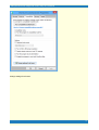
jClamp runs fastest when graphic settings in Compatibility mode are set.
Right click on the jClamp shortcut on the desktop and select properties.
Go to Compatibility
30
jClamp32 Whole cell voltage and current clamp 25.5.0 Manual
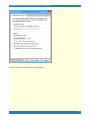
Change settings for all users
31
jClamp32 Whole cell voltage and current clamp 25.5.0 Manual
check the boxes (set to 16 bit color) then press OK.
32
jClamp32 Whole cell voltage and current clamp 25.5.0 Manual
Boxes are checked and dimmed out. Select OK to exit. You should have Administrater rights to do this. If not
change settings for just yourself.
File Types
File types
Protocol Files
*.prm these are protocol files that are built and saved in the Build utility window. They are the
basic file type used to collect episodic data (producing *.abf data files) and also to measure membrane
capacitance with 2 sine voltage stimuli (*.dcm data files automatically extracted from the *.abf files).
*.cmt capacitance tracking or gap-free parameter files that define the voltage delivery and
acquisition parameters for a time limited collection. The amount of time allowed is limited for both types of
collections since the intended use is for simultaneous output and input where the output command must be
33
jClamp32 Whole cell voltage and current clamp 25.5.0 Manual
confined to a limited array size. In the case of the Axon 1200A board, longer times are allowed than with
the other boards.
Utility Files
*.scp these are ascii script files that can essentially run an experiment by sequentially performing
a host of commands listed in the help file.
*.rpd these are ascii files that contain a list (up to 20) of the names of protocol (*.prm), script
(*.scp), and capacitance tracking or gap free (*.cmt) files. In the RPD window, these can be executed by
a button or key press.
*.scn Shot utility.
automatically generated screen arrangement file types. Created and utilized with Screen
*.ana analysis script file in ascii. Commands are listed in the help file.
*.uad user analysis directory of analysis script file names in ascii. This directory is used in the
Result Window to assign buttons to the individual listed scripts. The buttons are accessed by arrowing
down on the up/down control at the lower left in the Results Window.
*.fit ASCII text files of user equations for fitting data traces. See Fitting section.
Data Files
*.abf data files saved after running a protocol (*.prm) file. The file types are Axon compatible
and loadable in their programs, as long as Axon maintains compatibility with their earlier ABF version. This
filetype is also used to save gap-free data, when gap-free saving checkbox is enabled.
*.dcm extracted (from the associated *.abf file) capacitance data files that are opened and
viewed with the CC data plot window. After version 5.3.0, cm cal file is appended. The dcm save file
checkbox must be enabled in the ini file under History Tab for files to be generated. DCM files can be
generated from abf files in the FileMath window.
*.cm capacitance tracking data files that are opened and viewed with the CC data plot window.
Text (ascii) or binay set in inifile.
*.cal capacitance tracking calibration files. Text file. See Cm Tracking. .
*.cc
Cell Censor data that is collected when save is enabled in the cell censor window – all
parameters, e.g., Rs, Rm Cm etc are saved. These data files that are opened and viewed with the CC data
plot window. Text or binay set in inifile
*.not these are note files that can be audio, video, or text. If collected during saving of CC data
(*.cc) then markers are visible in the CC data plot window that allow viewing upon clicking the marker.
Also accessible from the logger window. Otherwise, the appropriate viewing window must be opened from
the CC window.
34
jClamp32 Whole cell voltage and current clamp 25.5.0 Manual
Update tips
Automatic updates:
If your computer is connected to the internet, jClamp, when run, will automatically check for
new updates on the web (currently at www.scisoftco.com/jclamp.html) if enabled in the ini file
under the Script Tab. Installation of new versions is also automatic. There may be either of two
kinds of updates – a full update which requires running a Microsoft MSI installation file (if you
do it manually then you first run the file to uninstall the last jClamp version and then run again
to install the new jClamp version), or a quickie update which only replaces the <jclamp32.exe>
executable file with other files, as needed. The update files are now named with version number
– the quickie file will have the form <jc_exe.v.21.10.12.exe> and should placed in the jClamp32
directory for extraction, and the full MSI file with the form <jClamp32_v21.10.2.msi> should be
saved to the <jc_msi> directory under the jClamp32 directory. If you update automatically from
the web the files are downloaded in the appropriate directories and run automatically.
You may turn off checking for updates in the ini file under the History tab, but will still be
offered the opportunity to check for updates in the Identity Window when jClamp starts or in
the About windows accessible from the popup Bar menu at extreme left movement of the
mouse.
Manual updating.
Upgrading to a new version is simple with the Microsoft installer. Download the msi file into a directory on
your hard drive, say, ... /jclamp32/jc_msi/.
jClamp installation file (double clicking on this file will install or upgrade [or repair] jClamp)
jClamp32.msi
To install a new version double click on the jclamp32.msi file and remove the old version first. Then double
click on it again and install the new version. All files that are initially delivered with jClamp, e.g.
jclamp.ini, and parameter files, are replaced; so if you use those (which you shouldn’t – make your own
with new names) make backups. The jClamp32.lic is not replaced! If your hardware license, your_name.lic is
in the jClamp directory it will not be touched, and it can be copied and renamed anytime to jclamp32.lic. You
can keep a back up store of the msi versions for safety, as the automatic installation does in /jclamp32/jc_msi/
.
special files for installation on old Win95 machines may be obtained by email to me.
w95.bat
oleaut32.dll
regsvr32.exe
SCRRUN.DLL
JC readme utility
Jcreadme.txt -- This is a new method for communicating with a jClamper during experiments without
interference during recording. A text file named "jcreadme.txt" can be placed in the jClamp32 directory at
any time, e.g., remotely via network. This note will pop up at the start of jClamp or, if jClamp is running,
35
jClamp32 Whole cell voltage and current clamp 25.5.0 Manual
when the Cell Censor is turned off. The note can be printed prior to exiting the window. Upon exiting, the
file is deleted, but the information is stored in the file "jcreadme.bak".
Additionally, if a text message is present, the audio file named <jcreadme.wav> located in the jClamp
<sounds> directory will be played. You can record your own audio message (using Windows sound
recorder, for example) along with the text message or just play a notification sound when the text message
opens. Just rename your recorded wav file to <jcreadme.wav> and place in the <sounds> directory.
A separate Audio program (jc_audio.exe) for recording/playing MS wav audio files, which can be played
during script execution now, since Windows Vista does not include one. Located in the jClamp directory.
It is a good way to remind yourself or another jClamper of something important!
36
jClamp32 Whole cell voltage and current clamp 25.5.0 Manual
jClamp for Windows - Details
Data Collection
StartUp
Start Up
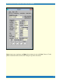
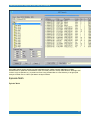
Upon double clicking the jClamp icon, a window is displayed requesting user identification. First and last
names are required, and may be specified in the INI file. The initials of the first and last name are used to
name files and data directories automatically (see below). The current INI file is indicated, jclamp32.ini
being the default. A scroll box displays other INI files available in the JCLAMP directory. Clicking on the
INI filename loads the file, and also displays a unique user graphic set in the INI file. An image of the user
is an ideal graphic for identification. The data path and the drive’s free space is also shown. INI files are
setup using the separate program iniedit32.exe. A user INI file can be loaded in place of the default
jclamp32.ini file if the file is appended to the command line (for example, in a shortcut icon), c:\jclamp
\jclamp.exe myfile.ini. Clicking the EXIT button unconditionally closes the program. After clicking the
OK button, the Cell Censor window appears and the Menu Bar is accessible by moving the mouse
cursor to the extreme left. If data had been previously saved to the data directory of the current day, a
flashing window indicates the number of old files and the next file will be automatically named with a
higher number - no fear of overwriting.
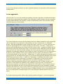
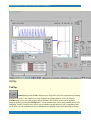
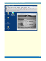
Often times jClamp windows will be arranged to suit a particular working condition. It is possible to save
the arrangement information for quick retrieval rather than repeatedly aligning windows manually. Clicking
37
jClamp32 Whole cell voltage and current clamp 25.5.0 Manual
on the main screen with the right button opens a small Screen Shot window
.
Clicking again on another area of the screen moves the small window to that area. To save a particular
jClamp window arrangement type in a file name (do not add an extension; the default is “.scn”) and click
the disk icon. To retrieve arrangements, double click on the filename in the screen file list box. Clicking on
the screen with the left mouse button simply closes the Screen Shot window. jClamp was designed to
use a screen resolution of 1024 x 768, 16 bit color and small fonts – all set in the Windows Display
property settings.
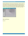
Menu Bar
Menu Bar
Accessed by moving mouse to extreme left of jClamp main window. If desired, the bar can remain visible
by moving it (move mouse after mouse cursor is down between icon and X button). Closing the
MenuBar window with the MenuBar’s X button sets it back to the hidden position. If the MenuBar
becomes somehow inaccessible, simply click on the main window’s X button in the upper right corner. It
should reappear.
38
jClamp32 Whole cell voltage and current clamp 25.5.0 Manual
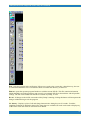
Exit - exits the program after verification. If data were saved to the current day’s data directory, the user
is notified that data files exist. If no data has been saved then the directory is removed.
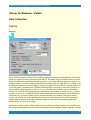
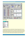
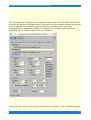
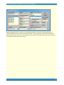
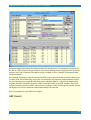
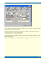
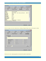
Edit ini - opens the separate program Iniedit.exe with the current INI file. This file contains information
which should be set for the program to run correctly. An example INI file is shown below with all possible
settings. The file can be edited with Iniedit.exe outside of jClamp, as well.
Re-ini - if changes to the ini file were made while jClamp is running, clicking this button will incorporate the
changes without having to exit the program.
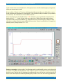
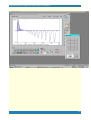
CC history - Displays a plot of cell and clamp characteristics during the past N seconds. N and the
sampling resolution are defined in the ini file. Three plots are available, but each can be used to display any
of the Cell Censor data items or data from Chan Watch.
39
jClamp32 Whole cell voltage and current clamp 25.5.0 Manual
Seal - Display input resistance during seal formation. Zap is a parameter file which can be modified by the
user. The scroll bar dynamically increases or decreases the amplitude of the signal. Pressing the cartoon
button delivers the zap stimulus which hopefully will establish whole-cell configuration! If not, suck! One
zap can be delivered automatically when a given seal value is reached, if auto is enabled. Settings in the ini
file.
Command Utility - the Command utility is used to develop voltage or current protocols.
Quick Notes open window to insert preassembled, often used notes into the log file.
Rapid Parameter Directory toggle open.
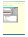
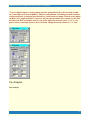
Edit Script - opens Notepad to edit script files with the extension <.scp>. An example script is shown
below with all commands. Scripts can be edited with any text editor.
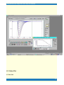
Impedance analysis – open impedance window
Cm calibrate icon. - capacitance tracking calibration and calibration file load . Calibration accessible from
CC window now.
??About - info on the jClamp and computer. The Help file can be accessed from here as well.
LOG open log window – only works in analysis mode.
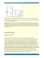
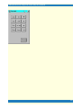
Model - the program can be run without hardware if model is selected from the Cell Censor window
(move mouse over the user graphic in the Cell Censor open selection window containing model toggle).
Clicking this button opens a window to adjust model cell characteristics.
Analyze - opens a window to permit some analyses.
Communications - GPIB (under construction) and serial communications are available to control
peripherals. Control via scripts is possible.
Clipbrd - opens the Windows clipboard to view data which has been captured for pasting into other
programs.
Quick Shell
Move mouse over free space indicator to open quick shell. Add useful program links to run without leaving
jClamp. See the quick_shell.txt file in the jClamp directory.
40
jClamp32 Whole cell voltage and current clamp 25.5.0 Manual
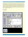
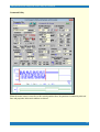
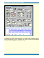
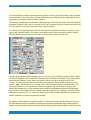
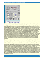
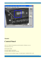
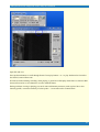
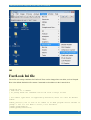
Cell Censor
Cell Censor
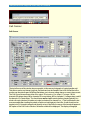
The top left corner of the window shows a graphic, in this case a photograph of a spiral ganglion cell.
This picture can be any bitmap (.jpg) that you desire and can be loaded in the ini file. Movement of the
mouse over the picture opens a window that allows you to choose voltage clamp or current clamp mode.
The Cell Censor channels are either 0 for output / 0 for input or 1 for output / 1 for input. V0 for
channels 0/0 voltage clamp, I0 for channels 0/0 current clamp, V1 for channels 1/1 voltage clamp, and I1
for channels 1/1 current clamp. The check boxes wc0 and wc1 control whether clamping polarity is in
whole cell mode (checked) or inside out mode (unchecked) for channel 0 or 1. This is equivalent to but
more accessible than inverting the polarity of input and output gains in the ini file. A math model can be
toggled on/off. If a board is present and properly set up in the inifile, the name of the board will appear in
the caption of the Cell Censor Window, otherwise model will be displayed. The display of telegraph
41
jClamp32 Whole cell voltage and current clamp 25.5.0 Manual
inputs from a patch clamp amplifier is also toggled on or off, showing an additional, separate window.
See Telegraphs. Enabling Dis_dual uncouples the default dual patch clamping setup (channels in/out: 0/0
and 1/1). If checked, you may deliver a separate command out of channel 1 by selecting chan 1 in the
Vhold box (see below), while monitoring channel 0 in CC. When in effect pulse stimulation out of channel
0 is stopped and is replaced by channel 1. In this way you can stimulate the cell with a mechanical
stimulus, for example, while monitoring the current response.
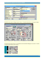
The Offset box allows one to zero amplifier offsets with the pipette in the bath prior to patch clamping.
The voltage offset correction is added to the command potential, but is invisible to the user. It can be
enabled/disabled with the check box, but will store the offset value when disabled. I prefer to use the
offset knob on the amplifier, but this will do it in software automatically.
The CC window can be collapsed by clicking on the left arrow bar on the upper right. At the bottom of
the window, the domain (time or frequency) can be selected for cell parameter tracking. See Cm
Tracking for more info.
CC on - checking this box begins monitoring of cell/clamp characteristics. The text “Save” of the
adjacent check box blinks, indicating that it should be enabled to save CC data (see below). Clamp time
constant (tau), electrode series resistance (Rs), membrane resistance (Rm), cell capacitance (Cm),
holding current (Ih), and series resistance-corrected holding potential (Vm) are displayed. If you place
the cursor over these values, a popup appears which shows the corresponding RMS noise value over a
short period of time.
42
jClamp32 Whole cell voltage and current clamp 25.5.0 Manual
CC save - if checked, CC data are saved to disk as an appendable ascii file readable
by any spreadsheet or text editor. The file is saved to <UserIinitialsDate.cc> ; e.g., JS96115.cc; this
file can be viewed graphically when the Analysis window is opened.
If the check box in the Ih display is checked then upon switching to current clamp from voltage clamp,
the holding current is transferred to current clamp mode. This should allow the cell voltage to remain
close to the same during the switch.
If the check box in the Vm display is checked then upon switching to voltage clamp from current clamp,
the membrane voltage is transferred to voltage clamp mode. This should allow the cell current to remain
close to the same during the switch.
CC inter - If checked then CC data collection is continued during protocol episodic and averaging
intervals; also during trigger waiting periods.
Cmd hld - Enable the use of protocol holding potential in CC during interval data collection; returns to
CC hold after protocol is finished.
Auto FileName - [This entry is now only in the INI file.] Enables auto file naming for collected data.
Files are named with the last name initial, date and a number ranging from 1 to 999. For example, if the
user name is Tom Jones, the first file of the day on 9/13/95 would be named <j5913001.abf>. For
months Oct-Dec, the initial are used instead; e.g., <j5o13001.abf>. Note that automatic directories are
made for each day, and are named with using first and last initials and the date. The directory name for
the information given above would be C:\TJ95913. If auto file save is disabled the user is prompted for a
filename.
Auto FileSave - [This entry is now only in the INI file.] file are saved after collection. If disabled the
user is prompted to save file.
Disable File - if enabled, no data is saved after collections and no prompts are displayed. This is useful
when equipment is being checked.
Chan Watch - if enabled, movement of mouse on this item will open a new window. Four channels (1-
43
jClamp32 Whole cell voltage and current clamp 25.5.0 Manual
4) in addition to CC Censor input (Ch 0) are allowed at a sampling rate defined by the user. Labels and
scales can be entered. These data are saved to disk with CC Censor data, and can be viewed with CC
History.
Digital Out - mouse movement over the icon of the amplifier will open a window which can set or clear
TTL level output on digital channels 0-7 (channel 7 is reserved for oscilloscope triggering). First select the
desired channel or channels and then press the Set button. The On column will indicate which channels
are on (high or 5V). The Clear button sets all channels off (low or 0V). The digital out set here is steady
state. Digital out can also be set in the Command Utility to provide transient or synchronous output with
the analog output signal. Following any parameter run, the digital channels are reset to the values set here
in Cell Censor, if CC on is enabled.
Vpulse - size of voltage or current pulse delivered to cell. Steppable from -40 mV to +40 mV in 5 mV
increments, or from -10 to +10 nA, in 0.1 nA increments. A value can be entered directly in the text box,
as well.
nAvg - number of pulses averaged to determine CC Censor data. The number of points (multiples of
512) for the stimulus is set in the INI file. The maximum number of averages depends on the number of
points (25 averages for 512 pt stimulus), since the stimulus is delivered as one array, and the maximum
array is about 16k. It is important that the current or voltage response reaches steady state in order for
Cell Censor to calculate the proper cell/clamp parameters. This is especially important when averaging
since the stimuli are delivered as a sequential train of pulses.
CC inter - time between data collections. With a 90 MHz Pentium and Stealth graphics accelerator,
data has been collected at 20 Hz with interval set to zero and no averaging. Most intervals set in jClamp
are estimates, since in Windows multitasking will not permit precise time definitions. Data collection
timing, however, is exact since DMA is used. If you place the cursor over the CC inter text box, a popup
appears which show the actual interval.
RPD - opens the rapid parameter directory window. Pressing insert opens and closes the window as
well.
Vhold or Ihold - sets the holding current or voltage for the CC channel or channel 1. Three predefined
(in the INI file) levels can be instantly set by checking the corresponding selector. For example, before
establishing whole cell mode, an appropriate holding potential can be set. The scroll bar can also be used
to set the potential, or a value can be entered directed by overwriting the indicated potential (blue
numbers). The holding potential is set for the selected channel, 0 being the Cell Censor channel, and 1
being analog channel 0. If PASS is enabled, then the CC holding potential is used for any subsequent
data collection via parameter files; i.e., the parameter file holding potential is overridden.
Sbutton - Movement over the S button will open a window to allow setting of holding potential stepping
information. Clicking on the S button will step the holding potential to the various potentials for the set
time interval. Check T to enable saving CC trace at the end of each step, and V to enable saving a video
clip at the end of each step. Executable in a user script -- see Script File.
Clk - sets the clock for the CC stimulus. Since the stimulus length is fixed, the clock is used to change the
length of time of the stimulus. For proper CC evaluation, the response must reach steady state, and this
can be achieved either by setting the clock manually in the text box, or by clicking on the transient trace
icon (which sets the clock automatically so that the stimulus delivery time is 10 times the response time
constant). Alternatively, AUTO can be enabled, which will periodically check for changes in response
44
jClamp32 Whole cell voltage and current clamp 25.5.0 Manual
time constant (actually clamp tau) and adjust the clock appropriately. If PASS is enabled, then the CC
clock value will be is used for any subsequent data collection via parameter files; i.e., the parameter file
clock is overridden.
NB - notes can be written to disk in either text format [click pencil icon] or audio format [click speaker
icon (if a sound card is present)]. This is most useful when CC Save is enabled, since links to the
comments are available when viewing the CC data file under the Analysis section. In addition, if a video
board is present with Video for Windows drivers clicking on the camera icon will open a window that
allows viewing and saving camera output in a scaleable window (see Look! Section of Help).
TeleShow - Toggle telegraphs display for amplifier - program interaction.
Channel Selection – Only channel 0 and 1 are available in Frequency domain mode. Choosing 0
(channels 0/0) selects output channel 0 and input channel 0 (e.g., connected to patch clamp #1 );
choosing 1 (channels 1/1) selects output channel 1 and input channel 1 (e.g., connected to patch clamp
#2 ); choosing B (both channels) alternates between channels 0/0 and 1/1 (pseudo-simultaneous
recording); choosing C (both channels) also alternates between channels 0/0 and 1/1, but measures
single cell information and responses in the adjacent cell – enabling estimates of junctional conductance.
Gj0 is the conductance between the cell recorded with amplifier #1 and that recorded with amplifier #2;
and visa versa. Series resistance and membrane capacitance are measured with the technique of SantosSacchi (J. Neuroscience 13: 3599 - 3611 ) by default, which is designed for simple, fairly small, single
cells, and is robust despite filter settings. There are two check boxes in the Rs Frame. If the top check
box is checked, the series resistance is and capacitance is obtained by Rs corrected - steady state
command voltage divided by maximum instantaneous electrode current (estimated at zero time), and total
integrated charge divided by Rs corrected - steady state command voltage. If the bottom box is chaeked,
Rs is ignored and input resistance is only displayed. Under this condition Auto clock is disabled, since tau
is not measured.
Check boxes in the plot window permit various options including automatic software selectable hardware
gain (if supported by the board); if disabled clicking on the gain number can scroll through hardware gain;
zero current trace; fix plot gain (normally it is automatically scaled to fit within the window) - if enabled a
spin button is used to manually changed plot gain; store function to maintain previous traces; FFT to look
at no-signal frequency response, clock initially set to observe 60 Hz noise - clock can be changed to
change frequency range. Beware of aliasing!
45
jClamp32 Whole cell voltage and current clamp 25.5.0 Manual
Quick Notes
The Quick Note window allows you to make quick note entries into the log file, and if CC save is on
have graphical displays (green bars) of the note in the CC data window which will open up to show the
text when the mouse is moved over the bars (see CC window below). Quick Note files are stored in the
application subdirectory <\quicknotes>. The file <quick_notes.txt> contains a list of notes (one per line)
that will automatically load into the Quick Note window. Selecting an item by mouse double click or by
pressing <enter> will load the text into the log (see log window below). If the item has the extension
<.txt>, it is treated as a text file, and all text in that file is loaded into the log. For example, at the
46
jClamp32 Whole cell voltage and current clamp 25.5.0 Manual
beginning of the day you could insert the methods, solutions, etc. into the log by double clicking on the
appropriate text file item.
At the bottom of the window is a text entry field where you can write any thing and by pressing the
command button insert the text into the log.
47
jClamp32 Whole cell voltage and current clamp 25.5.0 Manual
Stopwatch
There is a new stopwatch feature that can be accessed by clicking on the time display in the lower left of
the jClamp main window. More than one stop watch can be opened and remain floating on top. The
executable “stopwatch.exe” in the jClamp32 directory is shelled from jClamp or can be run outside
jClamp. Toggle between seconds only or minutes and seconds by single clicking on any dark part of the
watch. Set time in minutes and/or seconds in text box. Left button counts up; right button counts down to
zero and beeps; mddle button pauses. Double-clicking on the watch closes the watch. Mouse down on
the dark part and drag to move.
Seal
Seal
48
jClamp32 Whole cell voltage and current clamp 25.5.0 Manual
Displays input resistance during seal formation.
Zap is a parameter file which can be modified by the user. The scroll bar dynamically increases or
decreases the amplitude of the signal. Pressing the cartoon button delivers the zap stimulus which
hopefully will establish whole-cell configuration! If not, suck! One zap can be delivered automatically
when a given seal value is reached, if auto is enabled. Settings in the ini file.
Display channel is selectable.
Enabling audio produces a repeating beep at a particular frequency set with the Hz up/dn arrows. The
change in sound frequency (Hz/Mohm) is set in the text box. If you set thigs right you can hear a
difference when the electrode touches the cell.
Upon reaching 1Gohm a sound can be played. The file must be named <giga.wav>, a Microsoft wav file,
placed in the jclamp32 directory <sounds> subfolder.
In the <sounds> directory there is a file <no_sound.wav> that can be copied and renamed to
<giga.wav> so that no sound is played. jClamp now has a stand alone version of <jc_audio.exe> which
can be used to record or play wav audio files, since Windows Vista does not have a sound recorder that
does this. It is accessible in the jClamp directory or the jClamp start menu.
The time resolution of plot updates is the same as the History plot, which is set in the ini file, default 1 Hz.
Telegraph
Telegraph
49
jClamp32 Whole cell voltage and current clamp 25.5.0 Manual
Telegraph – under the Cell Censor window telegraph information is shown in a separate window if the
TeleShow box is checked. Only those channels enabled in the ini file are shown, that is, they must be
enabled in the ini file. Up to four channels are available for monitoring of Channels 0/0; and up to four
channels are available for monitoring of Channels 1/1. Same for chans 2/2/ and 3/3. The channel numbers
and function are set in the ini file. Available channels are from 4 to 15, but if 4-7 are used, Channel
Watch function will simply look at the telegraphs, and not be available for monitoring other devices. For
each telegraph, the channel numbers must be consecutive. Each channel(s) can have any of five functions,
viz., NC - not connected, VOLT - simple monitoring of the voltage on that channel, GAIN - monitoring
of gain telegraph output from a patch clamp amplifier, FREQ - monitoring of the filter frequency telegraph
output from a patch clamp amplifier, CAP - monitoring of the capacitance telegraph output from a patch
clamp amplifier, MODE - monitoring of the mode (voltage or current clamp or Izero) telegraph output
50
jClamp32 Whole cell voltage and current clamp 25.5.0 Manual
from a patch clamp amplifier. You should always shift from voltage to current clamp by first changing to
Izero. Amplifier knobs usually do this. For the Multiclamp, you should do this by mouse click in their
MultiClamp window. The GAIN and MODE are special cases where jClamp can take action on the
telegraph input. Therefore, check boxes are also displayed under these conditions. If enabled by
checking, GAIN will automatically rescale the incoming A/D data to correct for the new patch clamp
gain. If enabled by checking, MODE will automatically switch jClamp between current and voltage clamp
modes. The telegraph values are equated with their specific amplifier definitions in the INI file. If the
voltage connected to the MODE telegraph input is undefined (e.g. if the amplifier is turned off), then an
asterisk is displayed next to the mode which is set to the selected (checked) mode setting for the affected
channel. It is useful to use the VOLT function while altering amplifier gain or mode in order to determine
whether voltage levels are as specified in the amplifier manuals. If not, actual values can be used in the
INI file. Evaluations of telegraph input are made with an error window defined in the INI file. For the
DAQP-308 board only Gain and Mode are available for the two CC Censor channels, since only a total
of 8 input channels are available..
The telegraph inputs on the AXDD132x systems are not used. The above details apply instead.
51
jClamp32 Whole cell voltage and current clamp 25.5.0 Manual
The Axon Multiclamp Telegraph system is supported. Support for the 700A and 700B is provided. You
must select the Multiclamp telegraph checkbox in the History tab of the jclamp ini file editor and you must
select the channels to use (although the physical channels are not actually used). Also jClamp
automatically sets up telegraphs as enabled in the jClamp ini file. You need to supply paths to the
Multiclamp 700A or 700B executable (700A.exe or 700B.exe).
In the ini file under <History Tab>, you can set some features. Checking <no_tele> will disable telegraph
52
jClamp32 Whole cell voltage and current clamp 25.5.0 Manual
checking and allow you to enter a gain manually in the tele gain box. Checking <slow_tele> will allow
checking telegraphs every so often as a Windows clock allows, about a few hundred milliseconds, else
every time a CC data point is collected. If you check slow then CC collections could be faster. You may
need to check fast so you can switch between current and voltage clamp without a glitch (e.g., possibly
giving a larger stimulus than wanted [imagine in voltage clamp you give 10 mV steps in CC, then you
switch to current clamp. If jClamp doesn’t respond between the delivery of stimuli, it could be possible to
inject a 10 nA signal because internal scale factors would not have been changed to current clamp in
time]. For this reason default is fast check.
Chan Watch
Channel Watch
53
jClamp32 Whole cell voltage and current clamp 25.5.0 Manual
Allows user to sample up to four additional channels. Enable this selection in the CC window. Upon
moving the mouse over the enabled selection region, a window is displayed allowing the user to
individually enable channels 4 to 7, in addition to the CC channel (0). Collection is made at the rate
entered by the user, and the scales and labels for each channel are displayed. These scales and labels can
be entered here, but will be lost upon program shutdown. They can be entered permanently in the INI
file. A Chan Watch window is displayed, and shows the results of sampling. Data is also logged tot the
CC History window, and saved in the CC file, if saving is enabled. Note that if the sampling rate for chan
watch is faster than the sampling for CC then no CC collections will be made. Remember to always set
chan watch interval to a value greater than the CC sampling interval!
CC History
CC History
Displays a scrolling plot of cell and clamp characteristics during the past N seconds. The length of time
(N) is set in the INI file. The sampling rate (resolution) is also set in the INI file. Three plots are available
to view simultaneously, but each can be used to display any of the Cell Censor data items or data from
Chan Watch. Display channel is selectable.
If the DAX hardware is installed and enabled in the INI file, then selecting the DAX checkbox will output
a voltage representation of the selected CC History channels (up to four for Axon and Labmaster
boards, two for DAQP-308) frrom the DAX outputs. This output can be used to drive analog recorders,
such as strip chart recorders.
Command Utility
54
jClamp32 Whole cell voltage and current clamp 25.5.0 Manual
Command Utility
When the mouse cursor is moved over the vertical partition lines, the partition is bounded by thick red
lines and properties in the main window are shown.
55
jClamp32 Whole cell voltage and current clamp 25.5.0 Manual
The Parameter Load window opens up parameters into the command window. The parameter directory
is \param\ under the jclamp32 directory. All subfolders under \param\ are included in a search path when
a protocol is run from the RPD Directory window or via scripts.
56
jClamp32 Whole cell voltage and current clamp 25.5.0 Manual
Switch from ms to pts by clicking on pts/ms. Power of 2 up/down button shows (necessary fro chirp).
In Analysis mode, place mouse over command out selection and the holding level set in the CC window
just prior to data collection will be shown.
57
jClamp32 Whole cell voltage and current clamp 25.5.0 Manual
Command design is similar to Axon Instrument’s pClamp. However, the jClamp utility is more powerful
and user friendly. A user who knows pClamp will find that many build options are comparable. In fact, I
suggest that you read the pClamp (Clampex) manual.
The currently selected parameter filename is displayed along with its date of creation. The author field can
contain the designer’s name and if so desired, the file can be marked as private so that no other users can
view the protocol. A password is then needed to open the protocol.
A comment can be appended to the protocol. Check the box, and mouse movement over the box will
open up the comment window. For example, the solutions used for the experiments could be detailed.
Upon loading the protocol, the user knows that a comment exists if the box is checked.
Analog output depends on the board that you have. Version v.22.0.0 and later supports 4 DAC outputs
for the Axon DigiData 1440A, and IOTech Personal Daq. CED Power will follow. If you collect data or
make protocols with this version, then you will not be able to view them on the previous 2 DAC
versions. You may select any channel out and the associated input channel will be selected (a pop-up
window “Gain” will show this); e.g., selecting Chan 0 will select input channel 0, selecting Chan 1 will
select input channel 1, etc. If you select a channel not supported by your board then a pop-up will
indicate that. Alternatively, you can simultaneously synchronize multichannel collections with the Sync
drop down box. Selecting 0 will set up a single output/input channel (0/0). Selecting 1 will setup a dual
output/input collection (0/0, 1/1). And so on. Each parameter file contains information for separate and
distinct command waveforms for each output channel.
The number of input channels is limited to eight (0-7). Mouse movement over the InChan area opens a
box indicating the number of channels selected, their associated programmable input, and the physical
channel associated with the software channels. Double clicking on the channel number (in red) increments
58
jClamp32 Whole cell voltage and current clamp 25.5.0 Manual
through the available channels (0-7). Physical channels are sampled in descending order, i.e., in the
software channel order. Double clicking on the gain number for each channel (in blue) increments through
the available gain settings (1,2,4,8). In addition, the auto check box allows the users to obtain input at an
optimal gain setting for all channels. This works by setting the gain to maximum (8) initially. Each episode
is run and the data is checked for clipping. If the data is clipped then the gain is lowered to the next gain
setting and the episode is repeated. This continues until the data are unclipped or the gain is unity. This
process will maximize the resolution of the AD conversion, but will potentially deliver more voltage or
current stimuli to the cell than the parameter file calls for. Consider the benefits and disadvantages before
using auto gain.
The number of averages can be set as well as the time between averages. Each set of episodes is
performed, and the set is repeated for averaging. In the average frame a check box allows the saving of
individual data collections in a separate file, in addition to the averaged abf data file. The filenames for
individual traces (transformed into episodes for display purposes) are derived from the averaged abf
filename. For example, the file <average.abf> which contains averaged data from three episodes will be
associated with other files -- <average_AVG_1.abf>, <average_AVG_2.abf>,
<average_AVG_3.abf>, one file for each of the averaged episodes. This works with leakage subtraction
on, as well, and is useful for noise analysis where variance needs to evaluated.
The number of episodes can be set with an inter-episode wait time. The wait times (in msec) in jClamp
are approximate, since they are produced by the Windows environment. Data collection, however, is
exact since DMA transfer is used by the Axon acquisition board. In the episode frame a check box
allows delivery of episodes randomly. For example, if the command protocol has incrementing voltage
pulses of 10, 20, 30 and 40 mV, enabling random delivery will deliver the pulses in random order. If
averaging is on, each set of episodes will be delivered in the same random order.
Check boxes in the episode and average interval frames allow the capture of video frames after each
episode or average. Move the mouse cursor over them to identify them with the jClamp info panel.
Smart Averaging
59
jClamp32 Whole cell voltage and current clamp 25.5.0 Manual
There are an additional two check boxes in the episode and average interval frames which control
averaging. In the episode frame the left box is checked by default to average after completing all episodes
first. If unchecked the number of averages per episode are completed first before moving on to the next
episode. In this case, you may enable the Smart Averaging checkbox (left) in the Average frame, and the
Smart Avg window appears. Normally, when you supply a number of averages, the episode is run until
the total number of averages is complete. Now, you can stop averaging when a particular signal-to-noise
ratio (S/N) is reached as entered in the S/N text box. The signal RMS value from the chosen signal
partition (part S) is compared to the RMS value in the noise partition (part N). So if you select a S/N
ratio of 10, the response will be averaged until the ratio of RMS values reaches 10; if this is after 10
averages, averaging will be stopped even though the number of averages was set to 100. If the S/N is not
reached the total number of averages will be performed. The reject box is an RMS value of either the
signal or noise partition that will be rejected from inclusion in averaging, since it is deemed to be an
artifact. If the RMS value is negative then the whole episode (all partitions) is checked for potential
rejection. The combination of rejection and selected S/N requirements provides for powerful smart
averaging!
The Partition Design function produces the voltage or current waveforms. Holding potential is used at the
initial 6*partitions points, and for a variable number of points at the end of the command (at least
6*partitions points ) to make a total command length which is a multiple of 512 points. Clicking on mV in
the Properties Section changes the command window to current clamp mode, and clicking on nA reverts
back to voltage clamp mode. A partition is a number of points set to a particular type of waveform. In
designing a protocol one should first determine the number of partitions desired. Partitions can be inserted
before or after the currently selected partition (arrow down buttons), or deleted (X button). The
parameters of one partition can also be copied to one or all other partitions. Setting the partition number
to 0 erases all partition data. For a simple voltage step protocol, one partition can be used. Partitions on
the command plot are separated by red cursor lines. The number of points in each partition or time in ms
of each partition can be entered in the text box. Changes can also be made by cursor movements via the
mouse. Clicking on pts in the Properties Section changes the time input to milliseconds (ms); clicking on
ms reverts back to pts. Selecting custom points allows the extension of the ending holding potential in
increments of 512 points.
60
jClamp32 Whole cell voltage and current clamp 25.5.0 Manual
Step. ramp, stair, AC, abf and user stimuli are available for each partition. These are enabled for a given
partition by first selecting a partition by entering its number manually, or moving the mouse over the right
line cursor which demarcates the partition in the command plot. When selected, the cursors for a given
partition are highlighted green. Once selected, choose the desired protocol. Do this for all partitions.
The AC protocol allows delivery of single, dual or three simultaneous sinusoids. Maximum and minimum
frequencies are determined by the acquisition clock rate (on the main command window), and are
displayed. A given frequency is selected by choosing a multiple of the minimum frequency. The phase in
radians can also be set. Frequency increments can occur during multi-episode collections by setting the
multiple increment to greater than zero. If octave increments are desired, then set the increment to -1. The
second sinusoid stimulus can be enabled if desired, and its parameters set independently. The stimulus
may be either continuous, burst with a linear on-off ramp, or burst with a Hamming window. The duration
of the on-off ramp can be set to 1/8 or ¼ of the stimulus duration. Other AC stimuli, i.e., chirp
(logarithmically ramped frequencies), white noise (random noise) , or ternary noise (TN) can be selected.
Data obtained with AC stimulation can be analyzed with the built-in FFT analysis, or analyzed after
export to another software package.
It is possible to perform automatic capacitance measures (see Cm Analysis section) using the command
utility. Protocols are built as usual with step, ramp, user or ac stimuli in each partition. If the check box 1,
2 or eCm is on, either a dual or single sinusoid is superimposed upon the command in that partition. Fi2
checkbox enables one of two sine stimulus protocols – see Cm Analysis for details. From the recorded
currents, capacitance, membrane resistance, etc are derived automatically. It is possible to run dual
simultaneous capacitance protocols, i.e., Ch0 / out -in and Ch1 out -in. Build the command as usual for
each channel separately. A special protocol file accalib.prm is used to calibrate the system prior to
measurements. It is run automatically when the system is calibrated or can be run from the command
utility window, and a calibration file is saved with a selected name, e.g., test.cal. The calibration file
contains data for two channels. When one channel is calibrated, only the data for that channel is written.
If channel 0 and 1 are calibrated separately, then the two data sets can be put together in an ascii editor.
Alternatively, two systems can be calibrated simultaneously. It is now possible to derive Cm, Rs, Rm,
and Im from the abf file in the Analysis window. Most analysis features which are used for currents
(exponential fitting, etc) are then available to use. When a file that has employed 2 sine voltage stimulation
is viewed in the Open data file window, you can select to load the embedded calibration file (or use one
already loaded). Upon plotting in the abf file in the data Analysis Window, a box is displayed which
allows choosing which form of the data to plot – all automatically analyzed -- Raw, Cm, Rs, Rm, Im or
Vm. If a dual sinusoid command is chosen, then fusion event analysis can be performed.
When enabled, the user selection allows the incorporation of user defined stimuli into a command
waveform. Only one partition of an arbitrary number of partitions can be defined as a user partition. Only
one channel is allowed. The user waveform is actually added to an underlying step partition; voltage
starting level and increments are allowed therefore, but could be set to zero to deliver the user stimulus
“as is”, but riding on the holding potential or current. The number of points should be fixed, with no
increments (this is allowable actually, see below). First define a command protocol, setting up the userdefined partition as a step partition. After all parameters are set, then select user for the desired partition;
save the parameter file. The parameter file, e.g., jclampu.prm, must be associated with another file with
the same name but a usr extension, jclampu.usr, which contains the user stimuli in ascii format. The
values should be in mV or nA and arranged in one column. The number of values must match the number
of points (u-pts) in the user partition, else an error occurs. If the number of episodes is greater than one,
then the number of values must be u_pts * episodes, all arranged in one continuous column. The multiepisode stimulus can be a simple repeat of one set of u_pt values, or any individualized episode stimulus.
61
jClamp32 Whole cell voltage and current clamp 25.5.0 Manual
The number of episode stimuli in an ascii file can be greater than the true number of episodes in the
parameter file. This means that the user file which holds 10 episodes of stimuli can be used to deliver up
to 10 episodes without error. Partition point increments should be allowable if the user ascii file provides
incrementing u_pts for each episode. In this case, if an mismatch in number of points occurs the program
may crash.
When enabled, the abf selection allows the incorporation of user defined stimuli extracted from an abf file
into a command waveform. If the check box "abf template" is checked in the Partition Design frame, after
a collection a new protocol is built with the data just obtained as a command in one partition. So, if data
file "S0728002.abf" were just collected, a new parameter file "S0728002_abf.prm" will be created. As
with the user stimuli, the stimulus (abf) file must be copied (it is done automatically while making an abf
template) to the parameter directory where it is read during command build. This process can also be
accomplished within the parameter load window, where any abf file can automatically be recruited as a
command protocol. In the window, change the default file extension in the drop down box to “*.abf”,
select any abf file in any location on the disk, and press the “ABF_TO_PRM” button. This will copy the
abf file to the default parameter directory, and construct a parameter file named as above. In order to use
the parameter file, simply select and execute it as you would any other parameter file – through the
command build window, script file or via RPD. The abf file can be opened in the analysis window as any
abf file, and modified with epi math functions. Upon saving it back to the parameter directory, the
changes will be evidenced in the command when reloaded. More abf data partitions can be added to the
template, but the partition size can only be as large as the number of abf data points. Enabling abf in new
partitions will reuse the data from the abf file. In this way, repeats can be constructed with intervening
partitions of arbitrary stimuli. For example, synaptic currents recorded under voltage clamp can be fed
back to cells under current clamp. In addition to using any of the build command functions on the abf
partition, abf data can be modified via a box that opens when the mouse moves on the abf button. Scaling
and zeroing (relative to a point in that partition) can be done. While moving the mouse over these function
controls, see the information panel at the bottom of the jClamp main window for info on settings. These
features apply to user stimuli as well.
Digital output can be presented before the whole run (pre), before each episode (epi), during the
whole run (run), or synchronous with the analog wave form partitions (part). Selecting any of the first
three opens up a window allowing the user to choose which digital output channels should be used. The
time on and the time before starting the command delivery can be set. Exact timing may depend on
computer hardware, and should be checked with an oscilloscope. Partition (part) selection displays a
plot of the digital output from channels 0 to 3, and the level of these outputs can be set independently for
each partition (Dp check boxes set for each partition) and holding level (Dh check boxes). Additionally,
upon moving the mouse over Dp, a pop up window appears allowing flip-flop of digital output that
overrides partition settings. Set duration of pulses for whole duration of command. Negative duration will
invert pulses. The holding digital level is maintained if CC digital is not enabled, otherwise CC digital
controls output after the protocol is run.
62
jClamp32 Whole cell voltage and current clamp 25.5.0 Manual
The prepulse function allows delivery of a voltage stimulus prior to delivery of the command waveforms.
It is the same as Axon’s prepulse protocol. See there manual for details. The currents produced by
prepulse are not saved, however, average steady state values are stored to enable series resistance
corrections to the prepulse voltages (when using the built-in I-V plot window). When using prepulse,
there is a machine dependent time delay between the end of the prepulse and the beginning of the
command waveform. The time is somewhat variable and represents the time needed to fill the command
buffer with the episode voltage after the prepulse is delivered. The time on your machine should be
checked with an oscilloscope (it is about 10ms on a 90 MHz pentium). To help with this potential
problem, the INI file has a setting called prepulse_hold. If the value is set true in the IniEditor then the
final prepulse point is set to the protocol parameter holding level, filling the variable time with the holding
potential. If set false, then the prepulse time itself will include the extra variable time before the command
voltage. If the process being studied can recover during this extra holding time then use the command
protocol to deliver prepulses because the time between prepulse and subsequent pulses can be controlled
precisely in an episode.
The AXDD132x series systems, 1200 board and IOtech daq2000 do not have a delay between
prepulse and command for prepulse lengths less than or equal to 1 sec. Above one second, a delay of
about 40-80 ms occurs, which may be machine dependent. The National Instruments boards function the
same except there is no delay up to 10 sec. Check on an oscilloscope.
The P/N protocol is used to subtract leakage currents as described by Bezanilla and Armstrong. The
setup is the same as Axon’s, except that subtraction currents are always saved so that the user can toggle
between raw data and subtracted data traces. If you enable the Size checkbox, a fixed size (percentage
of commands) is given instead of P/N size. The number (N) of pulses at the subtraction hold potential is
still delivered, but appropriate scaling is made to subtract the linear currents. You can open the
63
jClamp32 Whole cell voltage and current clamp 25.5.0 Manual
subtracted files from the data load window (choose ‘sub’ extension). Currents are unit size before
scaling; you can confirm that subtracted currents are linear. If the currents are not linear the data file can
be un-subtracted in the analysis window to get the raw data to work on.
The command protocol plot can be updated after any changes by double-clicking on the plot or clicking
on the “All” button. Episodes can be displayed singly by clicking on the up and down arrow buttons.
Prepulse can be seen by enabling prepulse view. Clicking on the trace icon button copies the command
waveform to the analysis window for detailed viewing or export.
Data collection can be triggered externally or via keyboard. If Init is selected, then collection is
immediate upon RPD or script action. Trigger can be either by episode or by complete run, and can be
by key press or digital input (see supported hardware for input to use). Digital trigger now has minimal
delay between triggering and data collection, except for protocols with P/N, prepulse or CC inter use.
Plotting data during collection can be episodic, where each episode is plotted alone, or cumulative, where
all episodes are plotted with the most recent episode plotted in red.
During data collection, hitting the <esc> key will terminate the run. If some data had been collected, you
will be given the opportunity to save the partial data file.
Sister parameter files - individual files can be linked to follow each other (simple alternative to script files).
For example, jclamp.prm, test.prm, test1.prm, and test2.prm can be run sequentially by renaming first file
to jclamp[test.test1.test2].prm.
Pressing the DAX button displays the DAX window if at least one channel is enabled in the INI file. In
order to generate episodic commands for DAX the epi enable box must be checked. The command
holding potential, starting voltage and increment are set here. Only pulse warveforms are supported, and
are relative to the given protocol displayed in the Command window. That is, the DAX episodic output is
synchronous with an established main protocol for ch0 or ch 1 or both. Building the DAX timing ptotocol
is done in points only, and is relative to the timing of the main protocol. It can start and end before, during
or after the protocol.
64
jClamp32 Whole cell voltage and current clamp 25.5.0 Manual
MultiClamp IC <-> VC switching
Current and Voltage Clamp switching for the MultiClamp 700
jClamp can do real time switching between current clamp and voltage clamp in protocol files when an
Axon 700B Multiclamp amplifier is connected. The amp must be in external mode.
You will need to setup current and voltage clamp in CC window to make sure things are working first in
each mode separately. To measure Cm you will need calibration files for IC and VC, and the file names
need to be placed in the ini file. Everything I talk about here was done with an electrical model at the
headstage. Real cells require careful interpretations due to nonlinearities. To balance out stray
capacitance use the MD feature under Frequency domain. IC Cm is not as good as good as VC because
stray capacitance is balanced out with positive feedback and is achieved when the system is near
oscillation. Of course, you should back off compensation a bit so as not to kill cells with these
oscillations. You should have multiclamp telegraphs working in jClamp so gains and mode can be
65
jClamp32 Whole cell voltage and current clamp 25.5.0 Manual
registered by jClamp.
66
jClamp32 Whole cell voltage and current clamp 25.5.0 Manual
Multiclamp must be selected in the jClamp ini file.
67
jClamp32 Whole cell voltage and current clamp 25.5.0 Manual
68
jClamp32 Whole cell voltage and current clamp 25.5.0 Manual
69
jClamp32 Whole cell voltage and current clamp 25.5.0 Manual
Building a command starts with a voltage clamp protocol. Select Axon 700 mode [D3] and Part in the
Digital section. Digital output 3 is used to switch between IC (off) and VC (on). Trace 3 of the digital
protocol is red. By setting digital 3 for any partition, you can make that partition VC or IC. You can
select a partition from the drop down box or move the mouse onto red vertical line partition
demarcations in the command plot. When a partition is in VC, mV is displayed, and nA is displayed for
IC. Values are in nA for IC and in mV for VC partitions. Since the command plot shows both nA and mV
the view may appear odd. Select a partition to view the magnitude of that partition command.
70
jClamp32 Whole cell voltage and current clamp 25.5.0 Manual
71
jClamp32 Whole cell voltage and current clamp 25.5.0 Manual
To switch between VC and IC in CC when in ext mode in multiclamp, select V0 or I0 (Channel 0
amplifier).
Rapid Parameter Directory
Rapid Parameter Directory
72
jClamp32 Whole cell voltage and current clamp 25.5.0 Manual
Allows instant data collection using the selected parameter file, or script file. Can be used during either
Time or Frequency domain monitoring of cell parameters in the Cell Censor window. Parameter file text
appears in black. Script file text appears in red. Press the key or click the mouse. Pressing <Ins> key
opens and closes the window. The keys F1 thru F9 can also be pressed to initiate data collection without
the RPD window being open. Keys 1 thru 9 must have the RPD window open. Data are saved
automatically if auto save and auto filename are selected. After the data collection is complete, the holding
potential is maintained at the final potential in the protocol (usually the command holding potential);
however, if CC Censor is enabled the holding potential is set to the monitoring holding potential. Script
file execution can be cancelled using the mouse to click on the cancel button or by pressing the <esc>
key. A sample script file is illustrated below in the Script section (all commands are shown).
73
jClamp32 Whole cell voltage and current clamp 25.5.0 Manual
Use edit function to add new parameter file names to a rpd directory. Double click on an entry field and
a file box opens to allow addition of a parameter file, script file, or CMT file to the RPD directory. In the
file box window, use the extension selector to display each of the three types of files. Double click on the
filename and it is inserted into the RPD field. It is also possible to save and load different RPD
directories. RPD files are text files and have the extension <.rpd>; the file can also be edited in a text
editor.
DAX (Digital-to-Analog eXtra)
DAX (not available anymore)
·
·
74
jClamp32 Whole cell voltage and current clamp 25.5.0 Manual
oConvert digital outputs to analog outputs with the optional DAX (D/A eXtra) hardware addon. Control up to four more amplifiers. Monitor seal formation, set holding potentials, motitors
cell characteristics, sychronous episodic delivery. DAX hardware simply connects to the digital
out BNCs. The single male BNC connects to ch0, the attached white wire connects to ch1, and
the other four BNC assemblies attach to any of the digital out channels ch2-5. A 4.5 - 5 volt
power source (central pin positive) drives the DAX. Output from each channel is +/- 5 volts.
Cm Analysis
Cm Analysis
75
jClamp32 Whole cell voltage and current clamp 25.5.0 Manual
Starting in jClamp version 17.0 Cm analysis is more easily available from the CC window; now it is also
referred to as Frequency domain cell parameter estimation. You may toggle between Time and
Frequency mode on the fly. All selections in CC are enabled during CC data collection, for example, in
Frequency mode you may change analysis type (Single , Dual, eCm), or Sample Resolution, or holding
potential or Vpul size on the fly. 3 sine analysis is something in progress. Place the mouse pointer over
the values of Rs, Rm and Cm and a pop up shows the RMS value. Capacitance measures can also be
made within ordinary protocols -- see Command Utility. Now, CC Frequency domain analysis and
protocol analysis work together to get clean Cm measurements. Below is a description of sine wave
analysis in jClamp and more details about the new features.
For all methods except dithering, it is imperative that you calibrate your system! Things will not
work otherwise! See below!
76
jClamp32 Whole cell voltage and current clamp 25.5.0 Manual
Patch/cell model
Single sine analysis
The current that is measured under voltage clamp is the current through Rs, namely IRs. In the single sine
method a single sinusoidal voltage or current stimulus is delivered and the parameter values (Rs, Rm, Cm)
of the patch/cell model (shown above) are estimated. This method of Cm estimation is based on
evaluation of the changes of the capacitive current component of IRs, and arose from the initial work of
Marty and Neher (1981), who tracked current at a phase angle that approximated the angle of ∂Y/∂Cm.
This method was subsequently modified by Joshi and Fernandez (1988) to use the angle of ∂Y/∂Rs. See
their paper for the reasoning behind this choice.
The method I employ here I devised by careful inspection of the phase tracking techniques above, and
determination that the equivalent results are obtained by evaluating the imaginary component of IRs, B. Cm
is estimated by using the gain factor (Hc) of 1/∂Y/∂Cm, which is approximated (Gillis, 1995) by
Hc = 1+ tan2 (90o – Y) ω -1,
where Y is the admittance at the angular
frequency ω.
Cm= BHc .
A resistive measure (Rs) is estimated from the real component of Y, namely A, and scaled with abs(Y^2)
77
jClamp32 Whole cell voltage and current clamp 25.5.0 Manual
Unlike typical phase tracking paradigms, a point-by-point analysis is performed. However, since the gain
is approximated, the Cm estimate suffers from interference from resistive changes in the model. This
interference is alleviated by two additional methods that I have devised, the dual sine and eCm methods
listed below.
---- Phase Sensitive Detector (PSD) is exposed!
When single sine analysis is selected a check box is displayed which allows you to use the phase sensitive
detector. The method is detailed by Gillis, 1995, but instead of integrating over a full cycle, I use the FFT
to get at the real and imaginay component at any selected angle. Any angle can be chosen by moving the
slider. Right clicking increments by 1.57 radians. The angle of ∂Y/∂Cm (derived from two sinusoids – see
Santos-Sacchi, 2004) or the angle ∂Y/∂Gs – 90o can be set or toggled on for tracking. Zeroing and
scale selection of the in phase (Y1) and quadrature (90o, Y2) response is possible. Pressing the left and
right arrow keys will increment or decrement the PSD angle. You can use this see what angle is returned
by dithering either the Rs or Cm compensation controls. The buttons on the right side implement angle
estimation from dithering either the resistance or capacitance. Step one button is pressed to begin the
process; then either RS compensation or Cm compensation controls need to be changed a small amount
– no need to modulate the changes, just change a steady amount – then press step 2 button.
There is now a dither feature in the main CC window, which lets you repetitively dither Cm, Rs, or Rm
when the math model is chosen or dither a digital pulse when hardware is turned on. The pulse could be
used to dither Cm or Rs altering circuits. However, in the PSD mode there is a more simple dither
technique to get at the right angle for Cm measurement which follows.
For Rs dithering, jClamp will calculate the angle at which currents are unchanged by Rs changes. For Cm
dithering, jClamp will calculate the angle at which currents are unchanged by Cm changes. Cm dithering is
not really dithering the cell capacitance, so it is a rough estimate. Rs dithering will correct for changes in
Rs, but Rm may change. Thus, obtaining an angle to measure true Cm is not possible with this type of
dithering calibration. Using two sines, changes in all parameters can theoretically be separated. In any
case, this traditional single sine approach can be used and if after obtaining an angle for Cm analysis you
collect single sine data using a Command Utility protocol, the angle is saved with the data and can be
78
jClamp32 Whole cell voltage and current clamp 25.5.0 Manual
used to analyze current magnitude at that angle and 90 degrees from it in the Analysis window. You might
also use the digital out in a protocol to step a capacitance jump circuit in your patch clamp amplifier to
roughly calibrate the Cm (Mag0 and Mag90) measurements.
Dual sine Analysis
In 1991, I devised a method to use two voltage sine waves simultaneously to enhance the parameter
estimation method of Pusch and Neher (1988). A poster on the subject was presented at the Yale
Neuroscience Retreat in 1992.
The following description is taken verbatim from by funded NIH grant proposal (R01 DC02003,
submitted in 1992). Also, see the Detrending technical note supplied with jClamp, accessible from
Windows Start menu. It is very important to detrend the data when sinusoidal stimulation is superimposed
on rapidly changing voltage commands, as would be the case for investigation of voltage dependent
capacitance. Starting in version 17.11, a new method of detrending is used which does not add any
additional noise to the analyzed data. When you check the detrend button during Cm analysis a widow
pops up below the checkbox. The choices are auto and a range of numbers (detrending iterations) from
1-20. The auto feature chooses the correct number of detrend iterations, but there may be a number
below that which has less noise in the Cm trace, so you can choose the number of iterations manually.
Detrending removes rapidly changing currents (without filtering the 2-sine response) prior to FFT
analysis. See the Detrending technical note supplied with jClamp.
…. In the present experiment, a discrete frequency analysis will be attempted. Pusch and Neher
(1988) have used a single “tone” (sine wave, actually) technique to determine cell characteristics
under whole cell voltage clamp. By injecting a sinusoidal voltage into a cell, and measuring the
current response, they calculated from the system’s impedance, the cell capacitance, resistance
and electrode resistance.
Rs=(A-b) / (A2 + B2 - A* b)
Rm=1/b* ((A-b)2 + B2) / (A2 + B2 – A* b)
Cm=(1 / (ω * B))) ((A2 + B2 – A* b)2 / ((A-b)2 + B2))
where,
b=1/(Rs+Rm)
Y=1 / Zin
A=Re(Y)
B=Im(Y)
ω=2 π f
As can be seen, with the use of one “tone” (ω), it is necessary to obtain an independent estimate
of the input resistance (b). However, the utilization of a “two tone” (ω1 and ω2) stimulus allows
79
jClamp32 Whole cell voltage and current clamp 25.5.0 Manual
one to determine all parameters, given the signal and response. That is, b need not be determined
independently, and can be solved for, since, for example, Rs is the same at any two frequencies.
The evaluations should work under voltage clamp or current clamp. …
The implementation in jClamp allows the use of several different time resolutions which depend on the
selected clock. It is best to use the default settings, since only these have been checked to work
effectively, but feel free to try different settings and verify with electrical models. Real and imaginary
components of the current responses are obtained through Fast Fourier Transform. Remember the
analysis is model dependent (see model above), although the technique has now been extended to fusion
event (and junctional coupling) analysis – see help on Analysis.
jClamp now uses two approaches for 2 sine stimulation, one being the original implementation where
f2=2*f1 (index into the FFT array being 1 and 2) – the Fi2 checkbox is unchecked, and the other
f2<>f1*2 (index into the FFT being 2 and 3) – the Fi2 checkbox is checked. By making the latter
stimulus we avoid possible two-tone distortions such as sums and difference frequencies that can be
generated in a nonlinear system. Thus, for the original implementation, f1 of 390Hz and f2 of 781 Hz
could generate distortion components at f2-f1 which would sum with the f1 response and potentially
interfere with measurement of cell parameters. Other distortion components, e.g. harmonics, could also
interact with the primary frequencies causing problems. Now I introduce a 2-sine signal that is immune
from these effects. Since the indices are not harmonically related, distortion components of an f1 of
390Hz and f2 of 585Hz will not interact as before. The new implementation will provide a few
differences from the old one. For example, the old implementation at 10 usec, would produce six
resolutions at 0.16, 0.32, 0.64, 1.28, 2.56, 5.12 ms or correspondingly an f1 at ~ 6250, 3125, 1562,
781, 390, and 195 Hz, with f2 at 2*f1. On the other hand, the new implementation at 10 usec, will
produce the same six time resolutions at 0.16, 0.32, 0.64, 1.28, 2.56, 5.12 ms but correspondingly f1 at
~12500, 6250, 3125, 1562, 781, and 390 Hz, and f2 at ~18750, 9375, 4687,2343,1171, and 585
Hz. Two cycles of f1 and 3 cycles of f2 are used for each measurement of cell parameters.
In the method window, the dropdown box (selection 1,2, or 3) permits the extraction of Cm based solely
on w1, w2 or the average of the two, respectively. While using a math model produces equivalent results,
real world conditions (e.g., different noise levels at each frequency, changes in stray capacitance,
nonlinear distortion) may produce different results. Using 1 is probably best. Averaging was internally set
for jClamp versions 12.0 – 12.5.
eCm Analysis
This method estimates all parameters based on an exact solution of ∂Y/∂Cm and its angle. Though the
method uses two sinusoids to get at the angle of ∂Y/∂Cm, all parameters are determined from inspection
of only the low frequency response. The manuscript (Santos-Sacchi, Biophysical Journal, 2004) is in the
jClamp directory and is accessible from the Windows Start menu..
---------------------------------------------------------------------------------------------------------------------------------------------------
80
jClamp32 Whole cell voltage and current clamp 25.5.0 Manual
Single sine analysis is performed on the lower frequency, f1. For command protocols, the number of
frequencies can be set in the command window and is saved with protocols, so you can make and run
either 2 sine or single sine commands.
Notes on Calibration -- read this whole section!
Calibration can be initiated by clicking the ruler icon
in CC or in the Main Menu Bar, or by simply
running the <accalib.prm> protocol from the command window. In order to make accurate AC
measures, the frequency response of the system needs to be corrected for. When the calibrate button
(ruler icon) is pressed, a window appears and allows you to either load an existing calibration file, or run
a calibration. Upon calibration the red icon turns green. Any changes in the stimulus settings which require
a new calibration will require a new calibration file. The user must also recalibrate after changing the clock
or external filters. Filters should be set to a cutoff frequency (fc) less than that indicated. Calibrations can
be saved to or loaded from disk (ascii file named filename.cal) using the file command buttons.
Calibration depends on the pure resistivity of the calibration resistor, and in the case of the dither
technique, the pure resistivity of the whole dithering unit. Unfortunately, stray capacitance and inductance
accompanies these components. I find it best to work with low frequency stimulation, sine 1 at @ 390 Hz
and sine 2 @ 781 Hz, the default setting at a clock of 10 us. At these relatively low frequencies reactance
and inductance errors are not so great. Nevertheless, you should always check the reliability of the
measures with an electrical cell model.
The method for calibration is to use a resistor between headstage and ground. A value of 10 Mohm is
typical. During calibration, a window opens (see below) to allow entry of the exact value of the resistor
and the sample clock rate. The protocol file accalib.prm (accalibi.prm for current clamp) is used for
calibration and is run automatically during calibration. It can also be run manually from the command
utility (in which case it will simply open up the calibration window). The voltage magnitude, in the
protocol can be increased as long as saturation is not evidenced in the current response. The protocol
generates a correction file for the real and imaginary components of the system for 5 time resolutions
(which correspond to different frequencies in the frequency domain). The resultant calibration file has
calibration data for a given clock and filter cutoff; if either are changed another calibration file is
necessary. Remember that when used to measure cell capacitance the magnitude should be as small as
possible (I use 10 mV -- peak). See Takahashi S, Santos-Sacchi J, Distortion component analysis of
outer hair cell motility-related gating charge. J MEMBRANE BIOL 169: (3) 199-207, 1999 for
potential problems with the technique. The non-harmonic protocol now implemented in jClamp can
81
jClamp32 Whole cell voltage and current clamp 25.5.0 Manual
overcome these distortion problems if you have significant distortion. See description of the non-harmonic
technique above.
A new approach
I have devised a new way to get around some problems with stray capacitance, which heretofore had to
be removed by compensation at the amplifier. Now, although it is useful to balance out stray capacitance
to limit potential saturation of the amplifier, jClamp can automatically remove stray capacitance during
calibration and prior to cell recording.
The resistor should first be placed into the headstage connector. With the calibration resistor ungrounded
(and, if wanted, after stray capacitance compensation), press the Cs button in the AC calibration
window. Then after grounding the resistor, measure the resistor’s value in CC (you can check the lower
check box in the Rs panel in CC to sum Rs and Rm to get the resistor’s real value – jClamp tries to
separate out Rs and Rm and the sum of them will be the resistor’s value – remember to uncheck the box
when doing experiments), and enter the resistor’s value into the text box. Remember to enter the sample
clock you want to use. Press OK and the calibration file will be generated, and should be saved. The
calibration is automatically loaded after saving. When you want to record from a cell, you will typically try
to balance out stray capacitance after you get a gigohm seal, but it usually is not fully successful. To
overcome this problem, you may press the Cs button in the CC window after giga seal formation, prior to
popping into the cell. The button will turn green (if you click the button again the calibration will be zeroed
and the button will turn red). If the Cs check box is checked the Cs calibration data will be used to
correct sinusoidal response current before Cm analysis, if unchecked raw currents will be used for
analysis. Remember if you made a calibration file for 10 us and are using that, your clock in CC
Frequency mode must match that calibration clock, and furthermore the Cs button can only be used
when the CC clock matches the calibration clock. Whether or not you use the Cs to help remove
electrode stray capacitance, the main system calibration file will be used to correct for system response.
Thus, this new technique will remove any uncompensated currents due to stray capacitance so that the
calibration file (which also is now be made without stray capacitance interference) can accurately be used
to correct for system response. The check box next to Calibrate will allow you to see the calibration data
and Cs corrections that are currently being used. You can modify the calibration data real time to see
effects.
For current clamp the procedure differs, and an alternate window will appear – you must compensate
82
jClamp32 Whole cell voltage and current clamp 25.5.0 Manual
capacitance. The current clamp calibration window will open if CC is set in current clamp mode, else it
will open for voltage clamp calibration. Cm measures under current clamp are very tricky, and I am still
working on how best to do this.
In current clamp mode the resistor should be grounded and the voltage response to a short current pulse
should be squared by using the capacitance compensation. Then calibrate by pressing OK button.
Current clamp calibration and measurement are still under development. Beware!
Save the calibration data file and note that it can be reloaded (as default set in the ini file or at any time
with the file command buttons or menu bar button) and used only when the clock and filter settings in CC
and protocols match the original calibration settings. Remember, voltage and current clamp frequency
responses within the same amplifier unit may differ, so each may require using unique calibration files.
Each channel must be calibrated if you want to use them together or individually. You can calibrate
channel 0 first and save the data file, then calibrate channel 1 and resave the same file. The channel is
selected in the calibration window. When you calibrate, channel 0 is defined as channel 0 out with
channel 0 in, and channel 1 is defined as channel 1 out with channel 1 in. Check the goodness of the
calibration with an electrical model. You will need to balance out the model series resistance's stray
capacitance first which you can now do under whole cell conditions using the MD/Cs method – see
below. You can look at the calibration file in a text editor. The calibration values are listed for each
channel. If a channel is not calibrated, the list contains all zeros. At the end is a comment section where
comments on filter frequency, etc. can be added from the calibration window text box or in a text editor.
The default capacitance tracking calibration files (vClamp and iClamp) are set in the ini file.
Here is another point to remember. The Cm determination is model dependent and assumes no stray
pipette capacitance. This is also true when you use a model cell. If you have a commercial cell model,
typically (in the past) you cannot really balance out the stray capacitance of the series resistance under
whole cell conditions. Now this can be done suing the MD/Cs method below. Additonally, you could
not rely on balancing out in the patch condition – the MD/Cs method should work here, as well. To
confirm things, I have made a simple cell model in which I can manually disconnect the series resistance
from the cell parallel resistance and capacitance. Balance out the series resistance stray capacitance when
it is disconnected into the air as you do during calibration. Then connect the rest of the model and the
measured values will be quite accurate and should match those you obtain with the MD/Cs method.
If you create a calibration file using a 10 usec clock, and a 10 kHz filter between the amp and A/D
board, you may collect data at any of the 6 time resolutions (5 useable) noted above. The calibration file
that is loaded will be used and automatically chooses the appropriate resolution correction factors for the
83
jClamp32 Whole cell voltage and current clamp 25.5.0 Manual
data analysis. So, if you run only 10 usec data collections with that 10 kHz filter, then you only need this
calibration file for all data collections. If you change the clock to 20 usec or any other rate, or if you
change the filter, then you need to create a new calibration file with these settings that you must use (have
loaded) prior to collecting data with these new settings.
I suggest that you make a bunch of calibration files that are saved with different filenames, for example.
Amp1_10us_10kHz.cal -- Amplifier number 1 with 10 kHz filter collected with <accalib.prm> set to 10
usec clock
Amp1_5us_10kHz.cal -- Amplifier number 1 with 10 kHz filter collected with <accalib.prm> set to 5
usec clock
Amp2_10us_10kHz.cal -- Amplifier number 2 with 10 kHz filter collected with <accalib.prm> set to 10
usec clock
Amp1_10us_3kHz.cal -- Amplifier number 1 with 3 kHz filter collected with <accalib.prm> set to 10
usec clock
For calibration, if you want to make altereations, say, to voltage, the altered file <accalib.prm> or
<accalibi.prm> must be saved in order to use the changes.
If you have any other changeable equipment that could alter the system response, such as an analog
switch or multiplexer in the path, then any changes may require a new calibration file.
Each time you collect data at a given clock and filter frequency setting you must use the appropriate
calibration file. The resolution of the measurement that you select does not dictate the calibration file to
be used. This depends only on the clock and filter. jClamp automatically uses the appropriate corrections
from the calibration file to analyze at the selected time resolution.
After you make a calibration file, you should load it either by default on startup (set in the ini file), or
within a script file (before running a command protocol requiring the calibration file) or manually during
jClamp execution.
For command protocol data collections, the loaded calibration file is saved with the abf data file and is
automatically used for correction in the Analysis window (if enabled for use in the Data load window).
So, <abf> data files are saved raw and analyzed each time the file is opened. This means that for <abf>
files, different calibration files can be used to analyze the data, and therefore better estimates of the
system response can be used to correct the data post hoc.
Finally, be careful to understand how you might interfere with valid correction using a given calibration.
The calibration simply “flattens” out an “unflat” system response; it removes the system response from the
equation so you can accurately gauge the cell’s physiological response. Let’s review the calibration
procedure. When you place a pure resister between headstage and ground (and balance out the stray
capacitance), the response that you measure which deviates from a purely resistive response should be
due to the amplifier, filter, D/A characteristics and any other influential component that you have in the
path between that resister and the recorded response. If everything is done correctly with the calibration
(pure resistivity, accurate entry of resistance magnitude) then we get correction factors (for all the
84
jClamp32 Whole cell voltage and current clamp 25.5.0 Manual
resolutions at the given clock rate) that can be used to remove the effect of the equipment, and thus
measure the cell’s impedance correctly. In order to validly use the correction factors, you have to make
sure that after the formation of a gigohm seal, stray capacitance is balanced out (but see MD/Cs method
below) because the evaluation of the cell’s characteristics is model dependent and does not include a
pipette capacitance. Additionally, any manipulation of the amplifier after whole cell configuration could
potentially introduce changes to the state of the system that could invalidate the calibration. For example,
series resistance compensation may involve (in some amplifiers) an introduction of a lag in the system.
This could invalidate the correction values in the calibration file. You can check the effect of series
resistance compensation or other amplifier manipulations with an electrical model cell. I routinely will not
use this feature if I am doing capacitance measures. The best thing that I can say is that you should check
everything you might do with a model cell before trying on a real cell.
In-cell stray capacitance neutralization with software assistance
Although you may have made efforts to remove stray electrode capacitance prior to popping into a cell,
things may change during the course of an experiment. For example, fluid level may rise or fall around the
electrode and additional stray capacitance may interfere with Cm measures. I now provide simultaneous
multi dual (MD) sine wave analysis to handle this problem. In CC, select the MD checkbox and 5 dual
f1/f2 frequency analyses will provide a plot of Cm versus frequency index (low f to high f). Simply flatten
the line with electrode capacitance compensation circuitry on the patch amplifier to correct for stray
capacitance at all frequencies. Color of the line changes towards green as the correct compensation is
reached. An accurate calibration file is essential to use this feature. With this technique, you need not
worry if you pop into a cell before adequately compensating stray capacitance. It must be emphasized
that this procedure demands that cell capacitance must be linear, i.e., surface area dependent only. If a
nonlinear capacitance exists, this must be performed in a state where it is absent.
A Capacitance Compensation window is now available to aid in stray capacitance (Cs) compensation. It
is opened by checking the Cs checkbox in the CC window in Calibrate sub frame. Some amplifiers (e.g.
Axon Multiclamp) may not have enough compensation to flatten out the Cm vs F curve in MD.
Additional compensation is provided by the sliders. Start with the Cs0/Rcs0 slider first. One could do all
compensation with the software controls but it is better to balance fully with hardware if possible. This
software compensation works only under Frequency domain, but hardware compensation works under
all stimulation conditions since it is at the amplifier. One could compensate Cs in Freq domain and switch
back to Time domain knowing that the compensation remains in effect. It is really impossible to balance
out stray capacitance under the Time domain when inside the cell, thus the MD/Cs method is very useful
even if you do not do Cm measurements.
Under some conditions, it may be possible to compensate automatically in software. First adjust
hardware compensation just below compensation as shown in the red line below. Then press the guess
button followed by the fit button. The success of this depends on many factors, including the initial guess
result prior to minimizing to a slope of Cm vs F of zero. One last note, the Cs corrections are saved with
the data file and utilized during analysis – there is a Cs checkbox in the Analysis window which enables/
disable the corrections so that you can see the effect of having successful stray Cs compensation. Each
new cell must be compensated, and probably during an experiment with one cell you should check
compensation. The actual voltage delivered to the cell during MD stimulation is larger than a 2 sine
stimulus because 5 sines of equal magnitude are summed. Thus, you may want to consider the effect of
the stimulus on your cell. If necessary, you could reduce the stimulus size during compensation.
85
jClamp32 Whole cell voltage and current clamp 25.5.0 Manual
86
jClamp32 Whole cell voltage and current clamp 25.5.0 Manual
87
jClamp32 Whole cell voltage and current clamp 25.5.0 Manual
88
jClamp32 Whole cell voltage and current clamp 25.5.0 Manual
89
jClamp32 Whole cell voltage and current clamp 25.5.0 Manual
90
jClamp32 Whole cell voltage and current clamp 25.5.0 Manual
Model Cell
Model Cell
91
jClamp32 Whole cell voltage and current clamp 25.5.0 Manual
Cpip is pipette stray capacitance and Rpip is the resistance in series with Cpip. Values of 5 each
produce a transient current with tau of RC riding on top of the cell currents.
92
jClamp32 Whole cell voltage and current clamp 25.5.0 Manual
If Qmax>0 then a two-state Boltzmann is used to simulate a nonlinear capacitance in parallel with Cm.
Checking Vesicle switches to the model shown above. Gp is 1/Rp and Gv is 1/Rv. The standard model
is shown in the Cm Tracking section.
If Param change is enabled then any one of the possible parameters is changed from Val1 (at Pt1) to
Val2 (at Pt2). The value is ramped linearly from Val1 to Val2. The point values are the point numbers in
the episode of a command protocol. So it is possible to simulate vesicle fusion during the measurement of
capacitance (using eCm) by changing Gp between points Val1 and Val2. An example of this is shown in
the Analysis section.
Impedance analysis
Impedance Analysis
Analyze button will open a pop-up window to choose a protocol to run. Under voltage clamp,
<nyq_chirp_v_???.prm> or <nyq_sine_v_???.prm> are available with different voltage. Under current
clamp, <nyq_chirp_i_???.prm> or <nyq_sine_i_???.prm> are available. You can modify and save. Place a
resister or empty filter holder (for epithelial measures) and enter resistance determined from CC and
voltage (or current) to stimulate with, then run calibrate to obtain corrections for system characteristics.
You can enable or disable its use once collected. Calibrations are saved and automatically appended to each
data collection if the check box is checked. After data is collected, a fit to the chosen model can be
performed. For chirp signal, you may need to limit the points used for the fit to get better results – set the
deci factor above 1 to decimate (a value of 2 extracts an octave spread). When you open a data file in the
jClamp Analysis Window that has been collected with an impedance protocol, the Impedance window is
opened, data plotted and can be fitted. Check the Show box and the data are listed, hit <esc> and the listing
is aborted – it takes a long time to list the Chirp data at 32K length. Right click on table to copy any selected
data to clipboard. See jClamp Analysis Window help to see how to copy data to SigmaPlot, Excel,
MATLAB or Origin by dragging the icons within the Impedance window onto plots. You can enter a
surface area to divide currents by surface area with resultant changes displayed, check box enabling.
Reanliz button will reanalyze data; for example, after loading a new calibration file.
93
jClamp32 Whole cell voltage and current clamp 25.5.0 Manual
94
jClamp32 Whole cell voltage and current clamp 25.5.0 Manual
95
jClamp32 Whole cell voltage and current clamp 25.5.0 Manual
Look32X!
Look32x!
Video capture with jClamp.
This is a replacement for Look! and now supports VFW as well as
DirectShow compatible devices – web cams and other cameras with driver support. I have tested out
Logitech C300 web cam and perhaps it can be modified for microscope use. The Hauppauge video
capture boards continue to work fine.
If a video device is present clicking on the camera icon in CC will open a window which allows viewing
and saving camera output in a scaleable window. Streaming video capture and playback; record video
during data collections; control through script or via Look32X! video window. A stand-alone video
capture program, also called Look32X!, is available in the jClamp directory – useful to check that
cameras are working, etc. It is accessable in the jClamp start menu. Check script command section and
check menu on the Look32X! Window. I suggest a Hauppauge video (see www.hauppauge.com)
capture card - WinTV PCI - you can get them without the TV tuner for less than $100. The default
capture driver is number 0, but you can provide other numbers in the jClamp ini file under the "misc"
tab – if you have multiple boards. Setting the driver number to 999 causes jClamp to skip the check for
a board, and no capture will be available
As before, video can be captured via script files (see Script file help for commands). In addition, video
capture can be synced to protocol capture. In the command utility if a supported camera is attached,
you may select the LX check box in the Analog Channels area. When selected the light will turn green
and indicates that synchronous video capture will be made when the protocol is run. Video capture
will use the settings made in the Controls window (acessable from the Options tab in Look32X!
window. Gain, exposure can be set here is the video device supports these features. Under the
Options tab additional controls for video and audio are avaible from the camera manufacturer. You can
96
jClamp32 Whole cell voltage and current clamp 25.5.0 Manual
preallocate a disk file to save video so that disk access is faster. Size needed depends on the codec
used and length of recording. Play around to see what is best. If video is captured simultaneously with
a protocol, the Capture length value in the text box is ignored and capturing stops after the protocol is
run. Otherwise, the length may be fixed if collection is made directly from the Look32X! window or
limited by disk space if the fixed length checkbox is unchecked. You must then stop capture manusally
by clicking Stop Capture in Look32X1. Filename (Fn) prepend puts those letters at the beginning of the
captured video file. Filenameing and directory path are set frome jClamp. If run alone, default data
directory is “C:\Look32x_data\”. Manual naming can be enabled. The capture rate (frames per second
[fps]) can be set in Controls or under Options tab. Time lapse capture can be done for extended
periods of time. Video size (W and H) can be set in the Controls window or under Options tab in
Look32X!. All settings are dictated by the camera driver supplied by the camera manufacturer.
Multiple devices (cameras) can be chosen from if attached to the system. Preview must be set to
capture video. Overlay can be used to simply monitor in near real-time – for example to get patches.
You can zoom in (if Zoom is selected in the Controls window) by pressing left mouse button down
while dragging a box. You can crop (if Crop is selected in the Controls window) by doing the same.
With cropping only that portion of the image is saved to disk during video capture. Bitmaps of video
images (either jpeg or BMP formats) can be made during preview or playback.
97
jClamp32 Whole cell voltage and current clamp 25.5.0 Manual
98
jClamp32 Whole cell voltage and current clamp 25.5.0 Manual
When loading data files, if a file has an associated video file it is listed. FastLook! Vda files are
collected with Prosilica cameras (see FastLook! Help). If the check box near the video filename is
unchecked then the video file is not loaded when the data file is loaded. Otherwise, data and video
are loaded simultaneously (see below).
99
jClamp32 Whole cell voltage and current clamp 25.5.0 Manual
100
jClamp32 Whole cell voltage and current clamp 25.5.0 Manual
Video files, when loaded with associated data files are synchronized to the data. If you drag the data
cursor in the Analysis Window the video will step through frames captured at the time denoted by the
cursor. Alternately, you can step through frames in the Look32X Player and the cursor will move to the
corresponding time. On either side of the stop button in the Player you can automatically step forward
or backward. The rightmost button simply plays the video in real time. Synchronization can be turned
on and off with the LX checkbox under Cursors area of the Analysis Window. If turned off the cursor no
longer moves with the video, and all frames can be inspected (if synchronized, only frames within the
data time frame are accessable). Rectangles can be drawn on the video image to monitor average gray
level within the rectangle. Simply hold down the right mouse button and drag to size and release. Five
areas can be set (red, green, blue, yellow, orange). Click once one the rectangle then move mouse to
reposition; click again to dock. Double click on any rectangle to delete. The data are monitored in the
X,Y Levels window. Position of upper left corner and value (0-255) are given for each rectangle and for
mouse.
You can save data to disk if Export is set on in the Contols window (Measure tab). You can draw a line
(or average a few lines) by holding shift down and dragging mouse with left button down. A plot of
the intensity profile can be shown if Line Plot is checked. Below is a plot of the sinusoidal voltage
(blue) that drove an LED (red), made in Excel (see below) from the text output during a Forward play.
Whatever is plotted in the Analysis window is output (Im, Cm, Rm, Mag, Phase, etc.). Capture was a 30
FPS. You can see that there seems to be a delay between the two. It is not possible to get exact
synchrony in Windows with DirectShow cameras. This is only possible with triggerable cameras like
Prosilica’s (see FastLook help). You may try to better align video and data by using an alignment
procedure posthoc in the Analysis window. Move the mouse over the LX checkbox and a window pops
up. First place the cursor to a particular time where a fiduciary frame should be located. Enter the
frame number to associate with that time and press set. Now the frame will be
101
jClamp32 Whole cell voltage and current clamp 25.5.0 Manual
aligned to that time and all other frames appropriately shift in time.
Check synchronization with an LED driven by voltage stimuli in a protocol. You may want to inset an
LED into the periphery of the camera light path in the microscope in order to get fiduciary marks on
video captures.
102
jClamp32 Whole cell voltage and current clamp 25.5.0 Manual
103
jClamp32 Whole cell voltage and current clamp 25.5.0 Manual
Look32x Ini File – these data can be set upon starting Look32X!
;look32x.ini
; semicolon is a comment
capture_length(15); set the capture length to equal time in seconds
capture_timed(on); set capture length on/off
audio(on); set capture audio on/off
frame_rate(20); set fixed frame rate
;video_codec(DV Video Encoder);
video_codec(no compression);
audio_codec(PCM);
codec_quality(100);
time_lapse(2)
data_path:c:\look32x_data; set data path to c:\look32x_data ( the
current date is automatically added as a subdirectory. e.g. c:
\look32x_data\02-28-2010)
104
jClamp32 Whole cell voltage and current clamp 25.5.0 Manual
auto_save(on);
filename
auto or manual save -- manual asks for directory and
FastLook Video Capture
FastLook! Video capture linked with jClamp
In order to use FastLook, the fastlook checkbox must be set in the jClamp ini file. If it is not the
FastLook (FL) camera icon in the Command Utility window will have a big red X over it. If the ini file is
set, FastLook will open as an external instance, independent of jClamp, but linked to it via background
polling.
If enabled, moving the mouse cursor over the camera image will open a pop up window. Check the
FastLook Linker check box to allow digital out channel 0 to trigger the Prosilica video camera. The rate
at which trigger is performed is entered into the Rate text box. Digital markers are plotted where
trigger events will occur in time during the analog stimulus to the cell. Triggering is repeated for each
episode. You must make sure that the rate can be handled by the camera (see FastLook help file to
determine frame rate of the camera). You can run the command by pressing the Init button or by
saving the protocol and running from the RPD directory or script, as usual.
105
jClamp32 Whole cell voltage and current clamp 25.5.0 Manual
Data and video files are saved to the jClamp data directory. The filename of the video clip is a
combination of jClamp data file name and current time plus the extension “.vda”. In analysis window
opening a data file that has an associated video (vda) file will open FastLook internally within jClamp
for viewing of the video (see windows below).
IN the jClamp Data Load window, when an abf file is clicked on, if an associated FastLook video exists
it’s filename will be displayed. If the checkbox next to <FastLook Video:> is unchecked, the video file
will not be loaded when the abf data file is loaded. If it is checked both abf and vda files will be
displayed.
106
jClamp32 Whole cell voltage and current clamp 25.5.0 Manual
If the play button is pressed then the video will play and the jClamp red cursor will jump to each time
location where a video frame was captured. Pressing up/down frame will do the same. You can also
drag the cursor and the frames will follow the red cursor time.
107
jClamp32 Whole cell voltage and current clamp 25.5.0 Manual
Enabling Export data to file will save data read at each cursor position during playing to a file for future
analysis in external programs. Also video can be exported to ImageJ (see FastLook help file).
108
jClamp32 Whole cell voltage and current clamp 25.5.0 Manual
Script File
Script file Commands
· ;jclamp.scp ;semicolon precedes a comment
· p/n=true/false ; p/n leakage subtraction enable; automatic file naming and saving is toggled on/off in
Cell Censor Window or thru ini file.
· script=filename; call a script (filename.scp; don't use extension) from within a script
· cc_save=true/false ; save CC data to a file
· cc=on/off ; turn on/off Cell Censor
· auto_file_name=true/false ;enable auto filenameing
· auto_file_save=true/false; normally set in ini; enable/disable automatic file saving; if disabled, user
will be queried to save
· avg_on=true/false ;enable averaging
· clk_1=20 ;set command protocolclock in microseconds
· play_sound=filename ; play a sound file (filename.wav; don't use extension) from within a script;
this is a Microsoft wav file that can be made with MS sound recorder and must be placed in the
jclamp <sounds> subfolder. jClamp now has a stand alone version of <jc_audio.exe> which can
109
jClamp32 Whole cell voltage and current clamp 25.5.0 Manual
be used to record or play wav audio files, since Windows Vista does not have a sound recorder
that does this. It is accessible in the jClamp directory or the jClamp start menu.
· pass_hold= true/false; enable/disable passing of CC hold to next parameter file that is run
· pass_clk= true/false; enable/disable passing of CC clock to next parameter file that is run
· disable_file=true/false; enable/disable file save box in CC to enable/disable automatic saving of data;
no user query will be made
· cc_inter=true/false; enable/disable cc collections during wait intervals of protocols
· inter_cmd_hold=true/false; enable/disable use of protocol holding potential during wait intervals,
else cc hold is used
· cc_alt_polarity=true/false; enable/disable alternate polarity flip of vpulse
· cc_fix_scale_0=value; fix CC scale value (height of plot window) channel 0 (value shown in tooltip
text on mouse movement over Fix checkbox)
· cc_fix_scale_1= value; fix CC scale value (height of plot window) channel 1
· cc_fix _0=true/false; fix CC scale enable/disable channel 0
· cc_fix _1=true/false; fix CC scale enable/disable channel 1
· cc_pulse_0=value; pulse size in displayed units channel 0
· cc_pulse_1=value; pulse size in displayed units channel 1
· cc_navg=1-49; number of cc_pulse responses to average for parameter calculations
· cc_ignore_rs_0=true/false; just get dc resistance and put into Rm parameter
· cc_ignore_rs_1=true/false;
· mark_it=true; put a time mark in cc data file
------------------------------------· cc_zero_0=true / false ; set togglable or settable options in Cell Censor
· cc_zero_1=true / false
· cc_fix_0= true / false
· cc_fix_1= true / false
· cc_clk_0=value; channel 0 CC clock
· cc_clk_1=value; channel 1 CC clock
110
jClamp32 Whole cell voltage and current clamp 25.5.0 Manual
· auto_clk_0=true / false
· auto_clk_1=true / false
· flip_trk= true / false; jss specific for Vpkcm tracking
· cc_hold_0=-90 ;set holding potential for Cell Censor analysis - scaling set in INI file
· cc_hold_1=-100 ;set steady state potential for analog output channel 1 - scaling set in INI file
· dax_hold_2;set steady state potential for DAX analog output channel 2 - scaling set in INI file –
gain tab, DAX gain text box
· ----------for CED Power use to control analog channel out #2
· dax_hold_3;set steady state potential for DAX analog output channel 3 - scaling set in INI file –
gain tab, DAX gain text box
· ----------for CED Power use to control analog channel out #3
· dax_hold_4;set steady state potential for DAX analog output channel 4 - scaling set in INI file –
gain tab, DAX gain text box
· dax_hold_5;set steady state potential for DAX analog output channel 5 - scaling set in INI file –
gain tab, DAX gain text box
------------------------------------------· wait=10 ;wait for 10 seconds before continuing; during this time, if Cell Censor is enabled, cell and
clamp characteristics are continuously monitored
· waitfor=... ;wait for the following conditions to be met before continuing; Cell Censor must be
running, cell and clamp characteristics are continuously monitored; hit esc key to exit waiting
switching between clamp types while under Cell Censor
· clamp_type_to(i) ;continue with script after switching to current clamp; e.g. waitfor=clamp_type_to
(i)
· clamp_type_to(v) ;continue with script after switching to voltage clamp ; e.g.
waitfor=clamp_type_to(v)
monitoring Channel Watch values
· chan_watch_chan#>(test_value) ;wait for channel # chan# 's value to be greater than test_value
before continuing script ; channel number can be 2,3,4 or 5; e.g., waitfor=chan_watch_2>(4) --when Channel Watch channel number 2 is greater than 4 scripting will continue
· chan_watch_chan#<(value) ;wait for channel # chan# 's value to be less than test_value before
continuing script ; channel number can be 2,3,4 or 5; e.g., waitfor=chan_watch_3>(6) --- when
111
jClamp32 Whole cell voltage and current clamp 25.5.0 Manual
Channel Watch channel number 3 is less than 6 scripting will continue
CC parameter dependent switch
· rs>(value); rs<(value); waitfor=rs>(10); continue with scripting after success – other clamp
parameters can be used as well – rm, cm, tau, hold_i, and vm.
· timeout=25; if condition does not happen within timeout seconds then continue; must be set before
conditional statements; default time out is 10000 seconds.
----------------------------------Here is an example of what can be done. Monitor a cell under voltage clamp. Track its membrane
current at a particular voltage. Run a script that collects some data in voltage clamp then pauses to
wait for the switch to current clamp. With the passing of holding current to current clamp mode
checkbox enabled in CC, switch to current clamp at the amplifier. With telegraphs enabled, CC will
sense the mode switch, and change into current clamp mode which will cause scripting to continue.
The protocol that can be subsequently run in the script could be an Iclamp parameter file that has its
holding current passed to it from CC (if passing hold check box is enabled), and increments test
pulses upon that holding current.
-------------------------------------------------------------------------------· screen_shot=name; name is a screen shot file name.scn used without the extension.
· note=This a test. This note can be used to indicate actions which the user needs to make before
continuing with Script execution. ; A note to the user will pop up and the program is suspended
until the okay button is pressed
· run=new1 ;run a parameter file
· jclamp_beep=1 (2, 3) ; make sound N number of times.
-----------------------------------------------------------· do ;
begin a do loop; all commands within the loop will be repeated loop=N times.
· loop=2 ;
end a do loop.
While a loop is running, hitting the “L” key will cancel the loop and continue with the following script
commands. More than one loop can be placed in a script.
Variables can now be embedded in a do loop. The variables are vara, varb, …varf and can be used
to represent any number in a script. Before the loop the starting variable value, e.g. vara0, should be
defined, vara0=5, and the increment varainc should be defined; upon encountering vara within the
loop, vara will become by a multiple of the loop number. If the variable ( e.g. vara0 or varainc) is
set to a question mark <?> then the user will be prompted during the script for an input value.
For example,
112
jClamp32 Whole cell voltage and current clamp 25.5.0 Manual
vare0=5
vareinc=3
do
wait=vare
loop=3
This loop will do three waits of 5, 8 and 11 seconds.
Another example,
timeout=50
varb0=10
varbinc=5
do
waitfor=chan_watch_2>(varb)
run=temperature
loop=5
This loop will watch channel 2 under channel watch and wait until it is greater than 10,15,20,25, and
30 before running the temperature.prm protocol. If the timeout of 50 seconds expires before hitting
the condition, the loop will continue and run the protocol. This loop could be used to monitor
temperature with channel watch (also saved in CC) and collect data sets as the temperature is
changed continuously and automatically from say, 5 oC to 35 oC. Imagine, you could do multiple
conditions, e.g. simultaneous pH, tension, etc. with channel watch!
----------------------------------------------------------------------------------· digital=01111111 ; set digital output – channels 0 through 7 if a digit is >0 then digital out is high,
else low; chan 5 - oscilloscope trigger - no care;e.g., digital=01234567 , digital=10000000
· shell (path & filename optional command line argument); an executable with or without a command
line argument; e.g. shell=test.exe commandlineargument
streaming video capture
· vidclip=filename.seconds ; for example vidclip=test.20 will save a 20 second capture to test.avi
· vidclip=stop ; stop capture if running
· vidframespersec=value ; value is frames at 1 to 30 per second
· vidcaptureaudio=true(false) ; enable/disable simultaneous audio capture
----------------------------------------------------------------------------· video_auto_interval=##; video time lapse interval in seconds
· video_grab_now=true; grab a video clip (bitmap; *.not extension) to disk
113
jClamp32 Whole cell voltage and current clamp 25.5.0 Manual
· video_auto=on(off); turns on or off time lapse video collection
· video=on(off); turns video on or off
· video_save_V=on(off); enable saving of an ascii file (same name as the avi filename but with
extension “.asc”) which holds info on frame number and pt within command protocol which
corresponds to frame, episode, time into command, and time after video start.
· load_cmt=filename; without extension (.cmt assumed); commands below still work but this does it
all!
· cm_trk=start (enable, record, stop) ; start, record or stop cm tracking
FastLook with Prosilica GigE
· fastlook=capture_frames; set to capture frames
· fastlook=capture_time; set to capture time
· fastlook=capture_length(###); in time or number of frames depending on setting above
·
· fastlook=fixed_rate_on; enable capture at fixed rate; useful for time lapse or fixed sampling
· fastlook=fixed_rate_off; disable capture at fixed rate; maximum rate will be used
· fastlook=set_frame_sec; set frame rate in seconds
· fastlook=set_frame_fps; set frame rate in frames per second (fps)
· fastlook=frame_rate(###); frame rate [time in seconds if < set_frame_time> is set, number of
frames if < set_frame_fps> is set]
·
· fastlook=disk_stream_on; set saving direct to disk, may be slow
· fastlook=disk_stream_off;
·
· fastlook=autogain; set gain automatically
· fastlook=autoexposure; set exposure automatically
·
· fastlook=bitdepth8; pixel depth 8
· fastlook=bitdepth12; pixel depth 12
114
jClamp32 Whole cell voltage and current clamp 25.5.0 Manual
·
· fastlook=savebox_on; capture only within boxed area
· fastlook=savebox_off;
· fastlook=showbox_on; show only boxed area
· fastlook=showbox_off;
·
· fastlook=movie_trig_on; hardware trigger for whole movie to start
· fastlook=movie_trig_off;
· fastlook=frame_trig_on; hardware trigger for each frame to start
· fastlook=frame_trig_off;
·
· fastlook=cap_vda_now; run capture to a vda file, fast capture to memory, slower to disk if set
· fastlook=cap_avi_now; run capture to avi file, slow capture
· fastlook=grab_bitmap; grab a bitmap image
CMT files can be run from the RPD or a script file
· run_cmt=test ; run the protocol in a script
· cm_calib_file=filename; load cm calibration file, do not include extension (default extension is
“.cal”)
· cm_trk_prepulse=true(false); choose to deliver prepulse
· cm_trk_prepulse_volt=-40; voltage of prepulse
· cm_trk_prepulse_dur=100; duration in ms of prepulse
· cm_trk_clock=20; set cm tracking clock in microseconds
· cm_trk_f1mult=2; set cm tracking f1 frequency as a multiple of fmin
· cm_trk_f2mult=2; set cm tracking f2 frequency as a multiple of f1
· cm_trk_time=10; set cm tracking recording time in seconds
· cm_trk_w/sine=true (false); set true to make capacitance measures during voltage commands
115
jClamp32 Whole cell voltage and current clamp 25.5.0 Manual
· cm_trk_clock=10; set clock
· cm_trk_f1mult=2
· cm_trk_f2mult=2
· cm_trk_time=3; amount of time to record
· cm_trk_gain=1; hardware gain select
· cm_trk_analog=false (true)
· cm_trk_digital=true (false)
· cm_trk_digi=1101; on (1), off(0) digital out for digital out 0-3
· cm_trk_dur=500; duration of voltage stimulus
· cm_trk_durinc=50; increment in duration every repeat time
· cm_trk_vstart=-150; start voltage of step command stimulus; if ramp then start voltage
· cm_trk_vinc=100; increment of voltage stimulus every repeat id step; if ramp end voltage of ramp
· cm_trk_stim=ramp (pulse); choose type of command stimulus
· cm_trk_repeat=true (false); repeat stimulus
· cm_trk_repeat_time=## ;set cm tracking repetition time in seconds
· hold_step=true; initiate hold stepping in Cell Censor
· hold_step_video=true(false); enable for saving video clip at end of each step
· hold_step_trace=true(false); enable for saving CC trace clip at end of each step
· comm=1 (2,3,4); choose serial out channel
· serial_command=any commands in ascii; supply command
· send_serial=true ; send it now
· script_data_directory=path; eg. C:\script_data, data files will be saved as first five leters of directory
and filenumber – scrip001.abf, scrip002.abf …, in that directory
· kill_files_from=< filename> ; list of files to delete; uses script_data_directory that was previously set
· kill_file=<filename> ; one file to delete; must state path and filename; wild cards allowable,e.g. *.*
116
jClamp32 Whole cell voltage and current clamp 25.5.0 Manual
Ini File
Ini File
Use the separate IniEditor to set custom settings for individual users.
117
jClamp32 Whole cell voltage and current clamp 25.5.0 Manual
Double clicking allows choosing files. Default parameter directory and subfolders for path are shown.
Analysis
Analyze Window
Analyze
118
jClamp32 Whole cell voltage and current clamp 25.5.0 Manual
Automation
Automation link with SigmaPlot 2000, Excel 9, Origin 6 or 8.1 or MATLAB >v.5.3. Program usage
must be enabled in the ini file under the 'Script' tab. Linking to earlier versions possible if supported by
those versions. If application icons are present in the upper right of the jClamp main page when in
analysis mode then the programs are available for use. When active, drag icon in upper right of main
jClamp window onto a graph and release -- in Analysis Window, IV-Plot Window or CC Data Plot
window -- and data is automatically transferred to the application and a plot is generated. SigmaPlot
templates (*.JNT) can be stored in the "jClamp32/sigmaplot" directory for use of user defined graphs.
Upon dragging and releasing the SigmaPlot icon, a list of template files is displayed and can be chosen.
Application files should be saved under new names before exiting jClamp or inactivating the application if
data loss is to be avoided. MATLAB commands can be run from analysis scripts. SigmaPlot transforms
can be run from analysis scripts. Origin LabTalk command can be run from analysis scripts. All
applications communicate with jClamp via Active X (Ole automation) except the older Origin program
which only supports slow, legacy DDE. Because of this, the full path to the origin executable, e.g., "c:
\microcal\origin60.exe", needs to be entered into the jClamp ini file in the 'Script' tab section. Otherwise
the application will not be recognized.
Automation links remain in effect when exiting Analysis mode. This allows quick reentry to analysis mode
rather than checking for connections each time. No need to double clik on the Sigmaplot, Matlab, Excel
or Origin icons in Analysis mode. If programs are available (but need to be set to check for [in in file])
then icons will display and drag/drop icons to transfer data will be immediately available.
In order to use SigmaPlot jClamp templates, available in jClamp SigmaPlot directory, you must load
them into the template.jnt files according to Sigmaplot instructions. The default template.jnt is located in
the SigmaPlot program directory (see below).You can add templates for access in jClamp by creating
your own in SigmaPlot and putting the names of the template in the jclamp/sigmaplot directory (e.g.,
make a file name "my_new_template.jnt" in the directory -- it can be an empty file, only the file name is
necessary and must match the template name "my_new_template" in the sigmaplot template.jnt file.
Check that the new template is available in SigmaPlot. It is required that you reload SigmaPlot to install
new templates that are added to template.jnt.
119
jClamp32 Whole cell voltage and current clamp 25.5.0 Manual
120
jClamp32 Whole cell voltage and current clamp 25.5.0 Manual
Sigmaplot transfers will now increment notebook numbers so that now saving with new names is not
required between jClamp->SigmaPlot transfers. jClamp data file names are inserted in notebook
sections.
All transfers of data to other program via automation will leave the automation program files open after
jClamp closes. You can continue work on the data in those programs (SigmaPlot, Matlab, Excel or
Origin ) and save what you like. Matlab will ask before closing, Xcel will ask to save data before closing.
SigmaPlot will not close.
Analysis Window
A large window displays the data file traces and permits certain types of data manipulation. Descriptions
of the button functions are provided in the lower main window panel by moving the mouse over the
buttons. Data is loaded with the file open button in the task section. Other options include: plot printing; IV analysis; zoom viewing; Cell Censor data viewing; toggling of leakage subtraction; exporting files into
abf format, Matlab format or ASCII format; clipboard capture of the displayed traces data or graphic
plot; file math capabilities; and episode math capabilities;.
121
jClamp32 Whole cell voltage and current clamp 25.5.0 Manual
Various plotting manipulations are possible with the mouse. Particular episodes and/or partitions can be
plotted, or all data can be plotted. Vertical scaling of traces is accomplished by placing the mouse to the
left of the y-scale where it changes to a magnifying glass image; press the left mouse button down and
drag it vertically until the desired selection is made (indicated by a colored bar along the y-scale). Upon
releasing the button, the traces will be magnified. Horizontal scaling is similarly done beneath the lower xscale. Double clicking on the plot or pressing the reset button will restore full trace scaling, if Fixed Scales
are not enabled. Fixed X and/or Y scaling is selectable By pressing the left mouse button down within the
graph area, which displays a open hand cursor, and dragging, the traces can be shifted around. A small
plot in the lower right shows the horizontal position during dragging. Movements of the mouse over traces
highlights the selected trace, and displays information at the bottom of the plot. Vertical movements of the
mouse to the right of the right y-scale displays a horizontal cursor over the plot with a text box indicating
magnitude. Y-scale values are changeable by clicking on them or pressing <shift><Y> -- current scale
loops through nA, uA, mA, and pA . Default scales are set in the ini file. X-scale values can be in points
(pts) or time (ms). Clicking on the x-scale label or pressing <shift><X> toggles between the two.
Plots can have axes or a scale bar. The scale bar will indicate magnitude for the plotted data. The scale
bar can be dragged to any location in the plot window. Select the corner of the scale and a finger pointer
122
jClamp32 Whole cell voltage and current clamp 25.5.0 Manual
appears; drag very slowly with the mouse down to a new location. In the scale bar mode, voltage
protocol is displayed as well. In addition, if the digital partition output is enabled in the Command
window, then digital output is plotted. In either plot mode, a colored marker (up to 3) can be placed on
the graph by clicking the right mouse button over the data plot. Left clicking on them will erase them.
The click clip check box if enabled will display a magnifying glass cursor which can be used to capture
x,y points from the plot to the clipboard. Points are appended to the clipboard with each left click of the
mouse. You can paste the data into any spreadsheet. Unchecking the check box clears the clipboard.
See info panel at bottom of main jClamp window for button info when mouse moves over each button.
They are enabled after a data plot is created.
If a ramp command stimulus was employed to collect any part of the data, a panel is displayed to allow iv plot generation
CC Data Plot Window button - use to view saved Cell Censor data (*.cc), capacitance tracking data
(*.cmt) , and capacitance data (*.dcm) obtained from protocol files (*.prm) that incorporate two-sine
voltage stimuli.
Two data files can be displayed simultaneously by turning on storage. The previously
loaded data plot is retained in the color green, and its filename is displayed in green in the Analysis
window.
Cm Analysis in the Data Plot Window
It is now possible to derive Cm, Rs, Rm, and Im from the single, dual or eCm method abf files in the
Analysis window. Most analysis features that are used for currents (exponential fitting, etc) are then
available to use on the extracted data. When a file that has employed 1 or 2 sine voltage stimulation is
viewed in the Open data file window (see that help section), you can enable a checkbox to load the
embedded calibration file (or if unchecked, use one already loaded or load a new one for analysis from
the Analysis window). A calibration file opened while in Analysis mode will only be used for analysis;
the data collection file remains the same, and can be changed only when Analysis mode it exited. Upon
plotting the abf file in the data analysis window, a panel is displayed at the lower right that allows
choosing which data to plot -- Raw, Cm, Rs, Rm, Im or Vm. You may also choose whether to analyze
with single sine, dual sine or the new eCm Method, and correct for series resistance effects on voltage.
The green scale icon can be used to load calibration files, and view current settings (in the jClamp info
panel at the bottom of the full screen). You may also choose to detrend data or not. You have to read
the detrending note if you superimpose sinusoidal stimuli on ramps or other fast time varying
commands. See the Technical Note in the Technical Note subdirectory under the jClamp
directory for information on detrending. Detrending now corrects without adding any noise to
the data.
If you set the angle to measure single sine in CC, it is available here in the PSD box. PSD must be
selected to use the angle to correct the magnitude of current at that angle and 90 degrees away, which
123
jClamp32 Whole cell voltage and current clamp 25.5.0 Manual
can be viewed when accessed under the X, Y drop down boxes. Also Real and Imaginary components
of the raw current can be viewed.
If you used the Cs feature in CC prior to collecting sinusoidal protocol data, you will be able to correct
for the electrode stray capacitance by checking the Cs box (which will only be enabled if you performed
Cs correction). The corrections are saved with the data file.
In the Cm analysis pane, the dropdown box “f1/f2” (selection 1,2, or 3) permits the extraction of Cm
based solely on w1, w2 or the average of the two, respectively. While using a math model produces
equivalent results, real world conditions (e.g., different noise levels at each frequency, changes in stray
capacitance, nonlinear distortion) may produce different results. Using 1 is probably best. Averaging was
internally set for jClamp versions 12.0 – 12.5.
Fusion event analysis is also possible. The following model is used. Basically, prior to vesicle fusion Rp
is consider to be infinite and the admittance of the cell prior to fusion is assumed to remain constant during
the fusion event. Thus Rs and cell’s admittance is mathematically removed from the circuit leaving only the
fusion vesicle for analysis (the manuscript detailing the procedure is in review and will be appended when
124
jClamp32 Whole cell voltage and current clamp 25.5.0 Manual
published). Below a math model simulation is analyzed.
A command protocol which measures Cm during a 1 second interval (10000 points at 10 us clock, 2.56
Cm time resolution ) with the eCm method will be run with the model setup below. With this set up, Gp
will initially be 1pS (1000GW ) at the start of recording; after 20000 points of the protocol have elapsed,
Gp will change to 200 pS, which initiates the fusion event. Gp will be ramped linearly between point
20000 and 70000 up to 100 nS, then will remain constant. Below are screen shots of the analysis. If we
look at the simple extracted Cm without fusion event analysis, the capacitance changes quickly over the
course of 100ms. This time course is not that of the fusion process. If we check the fusion event (FE)
checkbox and place single or linked cursors at the section before fusion, we see that in fact the
capacitance jumps to final values instantly ( the wiggles are due to the ODE solver). If we now change the
plot to the fusion pore conductance (Rp in the dropdown box), and switch to a plot of conductance, Gp
(<shift><Y>) we see that the time course of fusion pore expansion is about 500 ms, and the conductance
corresponds to the model settings.
125
jClamp32 Whole cell voltage and current clamp 25.5.0 Manual
126
jClamp32 Whole cell voltage and current clamp 25.5.0 Manual
127
jClamp32 Whole cell voltage and current clamp 25.5.0 Manual
128
jClamp32 Whole cell voltage and current clamp 25.5.0 Manual
IV Plot
IV Plot
Select iv plot button to plot a range of values (avg, rms, peak, integral, time to peak, time to positive ½
peak, time to negative 1/2/ peak) versus episode or voltage at particular partitions. If Rs check box is
checked then the voltages are corrected for series resistance obtained from CC or entered manually. The
129
jClamp32 Whole cell voltage and current clamp 25.5.0 Manual
open file button in the iv plot window will allow selection of multiple files of similar protocols to compare
plots. Order of plots are RGB then dark RGB, then all red. The text button will show all the x,y data that
can be copied to the clipboard and pasted into any other program. For i-v plots, the reversal potential
and resistance at zero volts are calculated for each data set plotted. Pressing the Erev button will copy
the results to the clipboard.
130
jClamp32 Whole cell voltage and current clamp 25.5.0 Manual
File Math
File Math
131
jClamp32 Whole cell voltage and current clamp 25.5.0 Manual
All these manipulations can be done in an external package after export of the data. This window is
exposed for those who wish to investigate what I have under construction.
Fitting
Fitting
Fitting of data traces in each of the three graph windows (Analysis, CCdata, and IV – in the Fit window
choose the desired target) can be made with built in and user defined equations using the LevenbergMarquardt method. In the Analysis and CCdata window, the fitted region is between cursors 1 and 2. In
the IV plot all data are fitted (but you can remove
points by
clicking on the data points in that graph). Built in functions will guess at initial parameters if the Auto
check box is set. Uncheck it if you wish to provide your own guesses in the text boxes. Upon typing
(actually upon key release) in any of the parameter text boxes, a trace in green is displayed to help with
initial guesses. Remember that initial guesses are crucial for successful fitting! All traces displayed will be
fitted. You should display only the traces that you want to fit.
132
jClamp32 Whole cell voltage and current clamp 25.5.0 Manual
Data from the fits are sent to the Spreadsheet in the IV window (see image below). You may then plot
the parameters vs any of the x-values in the IV window by clicking on the parameter column. Fitted
parameters, original traces and fits can also be exported in tab-delimited ASCII format for importing into
spreadsheets. Shift-click on Fit button will automatically copy data to clipboard for pasting. If the Man
button is checked then you may choose the filename to save as or accept a default. If auto is checked
then all subsequent fits are saved to the default filenames based on data filename. If group is selected
then all data is save into a common group filename. If param is selected then only the parameters are
saved. Sdev is the SD between real and fitted traces.
The user equations are placed in the user_fits directory under the jClamp32 directory. Use the open and
save buttons to access the files. You can also simply write the equation in an ASCII editor and place in
the user_fits directory. Each equation is housed in an ASCII file with the extension <.fit>. An example
of a double exponential fit is given below. The format must be followed. The word xdata represents the
x-values (in mV or ms) and the word Yfit must finally equate all previous equations. A semicolon must
end all lines, and the headings ([equations] and [initial…) must be used. Most math functions are
available. They are:
ABS, ACOS, ARCCOSINE, ACOSH, ATN, ATANH, SIN, SINH, COS, COSINE, COSH, TAN,
TANH, EXP, LOG, SQR, LOG10
Make sure that non-parameter names are unique, since they will be used to place their equivalents within
the final evaluated equation. For example, <ea> and <eb> below cannot be confused with any other part
of the equation. But if you used an <da>, then all the <da>’s in the equation would be replaced with <
a0*exp(-xdata/tau0)+c0> when I parse it.
---------------------------------------------------------------------[equations]
ea=a0*exp(-xdata/tau0)+c0;
eb=a1*exp(-xdata/tau1)+c1;
Yfit=ea+eb;
[initial guesses for parameters]
a0=1.8549;
tau0=0.57;
c0=15.3114;
a1=2.1495;
tau1=2.7654;
c1=15.3114;
--------------------------------------------------------------------------------------
133
jClamp32 Whole cell voltage and current clamp 25.5.0 Manual
134
jClamp32 Whole cell voltage and current clamp 25.5.0 Manual
VidClip
VidClip
Grabbingimages in the Look! Window saves image files to the day’s data directory (bitmap
format as a note file, *.not; rename it to *.bmp to open in any image editor or view it in jClamp’s
VidClip image viewer accessible in the Analysis Window). The VidClip viewer can be opened in
Analysis mode by pressing the VidClip button. Linear measurements can be made with the mouse after
calibrating X and Y pixels per unit. Always save a calibration image (known X and Y magnitudes) that
can be used to do the calibration. Press the Cal button then drag the mouse vertically along the known
135
jClamp32 Whole cell voltage and current clamp 25.5.0 Manual
length of the calibration image. Upon mouse release a window prompts for Y image size; enter and click
OK. Then drag horizontally over the known width of the calibration image. Upon mouse release a
window prompts for X image size; enter and click OK. A prompt for units appears; enter units and click
OK. Place the mouse over the Cal button and the calibration information is shown in the information
panel at the bottom of the main jClamp window. Help for other buttons is available by moving over the
other buttons. These values can be entered into the ini file for automatic loading. This is useful if the scale
of the video capture remains the same day to day. Otherwise recalibrate daily for proper readings.
Data Load Window
Data Load
136
jClamp32 Whole cell voltage and current clamp 25.5.0 Manual
Info button toggles information for all files located in the data directory, for example time, protocol, clk,
Rs, Rm etc. Select Export to Integer format to convert from floating point to integer data (saved in same
directory with “.dat” extension). Plots data as saving. Loadable in Axon Clampfit or Synaptosoft Mini
Analysis programs.
Auto plotting or printing is done for a group of abf files; scales can be fixed and set in plot window prior
to output; if the selected data files are two sine Cm collections, the plotted or printed parameter will be
the one selected prior to output. By default the saved calibration data for 2 sine files are loaded (calib
checkboc checked). Uncheck it to use the calib files already loaded. Axon ABF and DAT files can be
loaded. Extensions can also be PDF, and if selected, Acrobat or reader will be opened with the selected
file displayed. Use this to looked at scanned lab notebooks for each day.
Press search button to open ABF search engine.
ABF Search
137
jClamp32 Whole cell voltage and current clamp 25.5.0 Manual
Open ABF Search engine window from the Data load window. Ability to search ABF files in multiple
subdirectories for particular characteristics of the command protocol or clamp characteristics. Shift right click
on list to copy to clipboard, e.g. to paste into Excel. Copy all listed files to a new directory to do group file
analysis. Double click on a file to plot data in Analysis window.
Episode Math
Episode Math
138
jClamp32 Whole cell voltage and current clamp 25.5.0 Manual
139
jClamp32 Whole cell voltage and current clamp 25.5.0 Manual
140
jClamp32 Whole cell voltage and current clamp 25.5.0 Manual
CC Data Plot
CC Data Plot
141
jClamp32 Whole cell voltage and current clamp 25.5.0 Manual
Display channel is selectable. Choose Cell number and CC x and y data to plot. If parameter data files
and comments were collected while CC data Save was enabled, the CC data plot can be used to rapidly
access and display the data files and comments. Place cursor over the green (comment) or red (data file)
tags and the file names for either are displayed. By clicking the file names, the comments (audio, video,
text or cc clip) are displayed, played or the data files are loaded and plotted. As the cursor is moved,
data values for all CC data points are displayed in the text box on the right. Channel identification is also
indicated in the data text box. Data plots can be scaled or manipulated as for the Analysis plot – see
Analyze.
The buttons allow file operations, printing, including automatic printing of all CC data for a given cell,
trace fitting, and toggling between points or lines.
Opening the second display channel reveals more options such as linking the x or y scales in both plots,
exporting to ascii, and copying to clipboard. When both plots are displayed, both can be printed
together. At the bottom is listed the rms value of the data that is displayed in the plot window. Clip click
(see Analysis window) is available. If the x-axis is time then all data parameters are sent to the clipboard
at the selected time point.
The export button, if clicked with the left mouse button, will export the data from a single plot to an ascii
file. If it is clicked with the right button, all data for each cell are sent to seperate ascii files. CM and CC
data can be extracted this way. Data are written to the directory where the data file resides.
Series resistance correction of voltage is done when the Rs checkbox is checked. The value of the
resistance is entered into the pop-up text field. Additionally, the traces can be filtered.
142
jClamp32 Whole cell voltage and current clamp 25.5.0 Manual
Analysis Script
Analysis Script
Commands should be placed in a text file with extension <ana>.
Then place the file name in the User Analysis directory, e.g., my_analysis_directory.uad, which
is set in the inifile. No spaces allowed, except in the text of a note.
· wait=1000 (ms)
· beep=1 {2,3}
· note=text; as in script analysis
· do; as in script
· loop=##
143
jClamp32 Whole cell voltage and current clamp 25.5.0 Manual
· choose_files=true ;opens window to choose files to analyze; all commands which follow apply to
each file
· filename=filename; choose specific file from script
· do_iv=avg {peak,tpeak,integ,rms}; as in episode math
· episode=all {##}; show all episodes
· start_point=###;show from this point
· end_point=###;end at this point
· epi_avg=true; commands below as in episode math
· epi_rcfilter=Hz
· epi_gaussfilter=Hz
· epi_offset=##
· epi_sub=episode_number
· epi_int=true
· epi_diff=true
· epi_zero=##
· epi_set_pts=##
· epi_mult=##
· epi_add=##
· iv_print=true; print the i-v plot
· trace_print=true; print the analysis plot
· export=asc {mat,abf}; export file; files are put in subdirectory \export
· cursor1=#; set cursors
· cursor2=#
· cursor3=#
· cursor4=#
· cursor5=#
· cursor6=#
144
jClamp32 Whole cell voltage and current clamp 25.5.0 Manual
· partition=#; highlight given partition with cursors at start and stop
· sp_do_transform=filename.xfm ; run transform in SigmaPlot; transforms must be in the
\Transforms\ subdirectory of SigmaPlot
· ml_do_command=matlab command ; run MATLAB command
· org_do_command=Origin LabTalk command ; run Origin command
; raw data leakage subtraction
· sub_trace=#; episode to use as scaled subtraction trace
· volt_partition=#; partition number for voltage range
· leak_sub_part=#; partition number to be leak subtracted; use <h> for hold region
; automation export to external applications
; set SigmaPlot notebook template, else selection window opens; if set to "auto" then new notebooks
are created
; templates located in /sigmaplot/ subdirectory of jclamp32
· sp_template=templatename.jnt
· export_data_cc=matlab, sigmaplot, origin, or excel
· export_data_abf=matlab, sigmaplot, origin, or excel
· export_data_iv=matlab, sigmaplot, origin or excel
analyse cm abf file and plot; previously loaded data file must be a two sine or phase track Cm
collection
· select_raw=true
· select_cm=true
· select_rm=true
· select_rs=true
· select_im=true
· select_vm=true
·
145
jClamp32 Whole cell voltage and current clamp 25.5.0 Manual
· select_time_x=true
· select_cm_x=true
· select_rm_x=true
· select_rs_x=true
· select_im_x=true
· select_vm_x=true
set scales for plot of loaded data file
· fix_yscale=true or false
· y_max=value
· y_min=value
· fix_xscale=true or false
· x_max=value
· x_min=value
set fit parameters
· fit_on=true; open fit window
· fit_now=true, do fit now
· fit_target=analysis, iv, cc"
· fit_exp1=true
· fit_exp2=true
· fit_cap=true
· fit_bolt1=true
· fit_bolt2=true
· fit_line=true
· fit_user_equation=filename.fit ; replace with any user equation filename that is present in the
<user_fits> directory
146
jClamp32 Whole cell voltage and current clamp 25.5.0 Manual
· auto_export=true, false
·part=partition; partition to plot in Result Analysis Window; 0 for all
·group=true/false; check box in fit form
·param=true/false ; check box in fit form
·choose_files_from=<filename> ; list of files to analyze rather than choose from dialog; uses
script_data_directory that was previously set
·x_data_to_fit=<filename> ; x data for fit; uses script_data_directory that was previously set
·y_data_to_fit =<filename> ; y data for fit must be same length as x data; uses
script_data_directory that was previously set
·params_to_fit =<filename> ; parameters for fit passed to matlab environment; uses
script_data_directory that was previously set
·rs_cor=True/false; turn on/off rs correction
·rs_val_override=<value>; replace rs value to use for rs correction
·script_data_directory=path; eg. C:\script_data, data files will be saved as first five leters of
directory and filenumber – scrip001.abf, scrip002.abf …, in that directory
147
jClamp32 Whole cell voltage and current clamp 25.5.0 Manual
FastLook
overview
Hardware
Supported Hardware
Prosilica cameras (www.prosilica.com ) that are supported by their SDK are required.
Andor iXon X3 860 EMCCD Camera
148
jClamp32 Whole cell voltage and current clamp 25.5.0 Manual
The cameras are interfaced with jClamp patch clamp program to externally trigger the camera using a
variety of A/D-D/A boards. See jClamp website (www.scisoftco.com) for more information.
main
FastLook! Main Window
149
jClamp32 Whole cell voltage and current clamp 25.5.0 Manual
Capture VDA files or AVI files. VDA is much faster. Grab a bitmap during viewing or during playback –
see viewing VDA files elsewhere in this help file.
A box may be draw to select a region of interest (ROI) that will be captured when saving video. Frame
rates can be much faster when small ROIs are selected. After a box is drawn, and the mouse button is
released, the “Check max fps” checkbox is automatically set and a one second simulated video collection is
made with the maximum rate and frame time period displayed. Check the box again to see how fast the
capture rate is for any already drawn box. Simply press the left mouse button down on the screen to erase
the box and return to full screen collection mode. The max fps will be displayed for full screen. You can
reduce or increase the viewed image by changing the scale. Video collection is always done with display
disabled. By using binning (set in the control Panel), and small ROI, fast video collections can be made.
150
jClamp32 Whole cell voltage and current clamp 25.5.0 Manual
Control
Control Panel
Auto save is default. If unchecked you will be asked for a filename to save to.
In the Main Tab you can:
Set the capture length
Set capture length to equal frames
Set capture length to equal time in seconds
Set time out to wait for hardware trigger. If exceeded capture is halted but file is saved.
151
jClamp32 Whole cell voltage and current clamp 25.5.0 Manual
Set fixed frame rate
disk_stream_on -- when capturing video stream directly to disk. May be slower than to memory.
disk_stream_off -- when capturing video stream directly to memory before writing to disk
autogain --push autogain button to automaically set gain for proper viewing - see camera instructions
autoexposure -- push autoexposure button to automatically set exposure time for proper viewing - see
camera instructions
bitdepth8 -- set bitdepth to 8 bit (denoted by 0 in file header)
bitdepth12 -- set bitdepth to 12 bit (denoted by 1 in file header)
savebox_on -- save only that area of screen within a drawn box
savebox_off -- save whole screen
showbox_on -- show only that portion of the screen that is within the box
showbox_off -- show whole screen
movie_trig_on -- set whole movie capture (possibly consisting of many frames) to occur when hardware
trigger is sent to camera trigger input
movie_trig_off -- disable movie trigger
frame_trig_on -- set single frame capture to occur with each trigger input until number of desired frames is
acheived.
frame_trig_off -- set frame trigger off
fixed_rate_on -- set capture to occur at fixed frame rates This will be limited by Windows
fixed_rate_off -- no fixed frame rate speed will occur at maximum rate permited by software in Windows.
set_frame_sec -- set fixed frame rate in terms of time - duration of frame.
set_frame_fps -- set fixed frame rate in terms of FPS (frames per second).
The default directory for VDA files is “c:\fastlook_data\” plus the day’s date (e.g., see below). The
directory can be changed here in FastLook or in the ini file at program startup (see ini file section in this
help file). Thus, each user can set his/her own user directory.
When FastLook is used in conjunction with jClamp, jClamp control the data directory path directly.
Communication with jClamp is via background polling.
152
jClamp32 Whole cell voltage and current clamp 25.5.0 Manual
Calibrate check box will show two flashing white lines 100 pixels apart. Determine the actual size and place
distance and units to be saved with VDA files.
Simple measurements to plot line or box profiles or average of marked areas (RGB plot). Export VDA
video files to ImageJ to do sophisticated image analysis.
Delta length and save data are jClamp only features.
During image capture you can enable viewing of live images at entered frame rates. Uncheck box for best
high speed capture results.
If Frame marker is set a pop up window will appear during recording to allow a button press to mark the
frame for future identification in the video player. Can be set in ini file.
153
jClamp32 Whole cell voltage and current clamp 25.5.0 Manual
You can view the header information of VDA files that are being viewed.
154
jClamp32 Whole cell voltage and current clamp 25.5.0 Manual
You can overlay text on the video and save to bitmap. Playback frame rate for AVI export is set here.
You can set or view camera properties in the other Tabs of the Control Panel.
155
jClamp32 Whole cell voltage and current clamp 25.5.0 Manual
ViewVDA
View VDA files
The default directory is C:\fastlook_data. Select a file to view from the menu and a Open file dialog
window will open allowing you to navigate and select a file.
You can write an already opened VDA file to AVI format at the FPS rate set in the AVI Control panel.
You can export to ImageJ (see ImageJ Section in this help file).
Click on Player to open video player window.
156
jClamp32 Whole cell voltage and current clamp 25.5.0 Manual
Open file and view.
Press up/down buttons to scroll through frames. Press play button < or > to play backward or forward at
the desired, entered frame rate.
If frame are marked during recording, when playing, a green box will display when frame is selected. Shift
down on forward or reverse buttons to scroll to marked frames.
During real-time viewing or playing you can do some rudimentary measures, such as plot a line or box
intensity profile, or measure intensity of select points – see measure tab in Control Panel.
157
jClamp32 Whole cell voltage and current clamp 25.5.0 Manual
Right click and drag to place red, green, blue, yellow, and orange areas to measure. Double left click on
them to remove. One click on them to move, another click to set. Shift down, left mouse button down and
drag to draw line (thickness set in Control Window). Control Window has plotting and disk output options.
158
jClamp32 Whole cell voltage and current clamp 25.5.0 Manual
Simple left mouse button down and drag to draw box.
Scale video by dragging window to larger size.
imageJ
ImageJ Link
ImageJ is a free, powerful image analysis program from the US National Institutes of Health (http://
rsbweb.nih.gov/ij/download.html ). VDA video files that are being viewed can be loaded from FastLook into
ImageJ automatically from the Menu. Alternatively, VDA files can be loaded directly into ImageJ from its
Menu (see picture below).
The following two files, which are located in the ImageJ subdirectory of jClamp or FastLook, have to be
placed in the ImageJ directory, C:\Program Files\ImageJ\plugins\Input-Output, in order to work with VDA
files.
<FastLook_gui_loader.class>
<FastLook_loader.class>
Also, in the macro section of ImageJ you can load the scale for the image, if already set in FastLook, by
running "fl_set_scale".
159
jClamp32 Whole cell voltage and current clamp 25.5.0 Manual
160
jClamp32 Whole cell voltage and current clamp 25.5.0 Manual
ini
FastLook Ini file
The ini file sets startup conditions for FastLook. These can be changed in a text editor, such as Notepad.
Here is the default fastlook.ini file content. Commands set checkboxes in the Controls form.
;fastlook.ini
; semicolon is a comment
; in jClamp these ini commands can be run from a script as well
; set camera types here if supported by FastLook; value of 0 will be default
camera
camera_start(0); set to zero so no camera is on when program starts outside of
jClamp -- set to 1 for Ando to start, 2 for Prosilica
;camera_kind:andor=1;
;camera_kind:prosilica=2;
161
jClamp32 Whole cell voltage and current clamp 25.5.0 Manual
;camera_kind:spot=3;
ij_path:O:\imageJ; set ImageJ path here
capture_length(20); set the capture length
prosilica_poll_on; set polling with jClamp to control capture with a particular
camera
;spot_poll_on;
andor_poll_on;
auto_gain_threshold(700); set auto gain to obtain this average random pixel
intensity of camera image (not screen intensity!)
capture_frames; set capture length to equal frames
;capture_time; set capture length to equal time in seconds
time_out(10); set time out to wait for hardware trigger. if exceeded capture is
halted but file is saved.
frame_rate(25); set fixed frame rate
frame_mark_on; enable frame marking during recording
;frame_mark_off;
;audio_mark_on; enable audio frame marking
audio_mark_off;
audio_threshold(50); set audio threshold for frame marker (1-127)
;disk_stream_on; when capturing video stream directly to disk. may be slower
than to memory.
disk_stream_off; when capturing video stream directly to memory before writing
to disk
;autogain; push autogain button to automaically set gain for proper viewing see camera instructions
;autoexposure; push autoexposure button to automaically set exposure time for
proper viewing - see camera instructions
;savebox_on; save only that area of screen within a drawn box
savebox_off; save whole screen
shutter_open; open camera internal shutter if present
;shutter_close; close camera internal shutter if present
;showbox_on; show only that portion of the screen that is within the box
showbox_off; show whole screen
;movie_trig_on; set whole movie capture (possibly consisting of many frames) to
occur when hardware trigger is sent to camera trigger input
162
jClamp32 Whole cell voltage and current clamp 25.5.0 Manual
movie_trig_off; disable movie trigger
;frame_trig_on; set single frame capture to occur with each trigger input until
number of desired frames is acheived.
frame_trig_off; set frame trigger off
;fixed_rate_on; set capture to occur at fixed frame rates; This will be limited
by Windows;
fixed_rate_off; no fixed frame rate; speed will occur at maximum rate permited
by software in Windows.
;set_frame_sec; set fixed frame rate in terms of time - duration of frame.
set_frame_fps; set fixed frame rate in terms of FPS (frames per second).
;data_path:d:\test1 ; set data path to d:\test1 ( the current date is
automatically added as a subdirectory. e.g. d:\test1\02-28-2010) in jClamp
directory is auto set to jClamp data directory
--------------------------------------The default ini file can be replaced with any other ini file by appending the ini filename to the Target
command line in a shortcut on the desktop.
Here “myini.ini” will replace “fastlook.ini”. This is useful if more than one person uses the program and
needs to set different data directories and camera settings.
In order to be able to edit the properties of the shortcut, you need to go to the executable file “fastlook.exe”
in program files directory, right click on the file and send shortcut to the desktop.
Shortcuts made other ways may not allow editing the target.
163
jClamp32 Whole cell voltage and current clamp 25.5.0 Manual
164
jClamp32 Whole cell voltage and current clamp 25.5.0 Manual
Notes on CM calibration
Update Technical Note 3
SciSoft Company (www.SciSoftCo.com)
Notes on Calibration
Running the calibration parameter file, <accalib.prm>, generates a correction file for the real and
imaginary components of the system for several time resolutions (which correspond to different
frequencies in the frequency domain).
The file <accalib.prm> will produce corrections for six resolutions.
jClamp now uses two approaches for 2 sine stimulation, one being the original implementation where
f2=2*f1 (index into the FFT array being 1 and 2), and the other f2<>f1*2 (index into the FFT being 2
and 3). By making the latter stimulus we avoid possible two-tone distortions such as sums and difference
frequencies that can be generated in a nonlinear system. Thus, for the original implementation, f1 of
390Hz and f2 of 781 Hz could generate distortion components at f2-f1 which would sum with the f1
response and potentially interfere with measurement of cell parameters. Other distortion components, e.g.
harmonics, could also interact with the primary frequencies causing problems. Now I introduce a 2-sine
signal that is immune from these effects. Since the indices are not harmonically related, distortion
components of an f1 of 390Hz and f2 of 585Hz will not interact as before. The new implementation will
provide a few differences from the old one. For example, the old implementation at 10 usec, would
produce six resolutions at 0.16, 0.32, 0.64, 1.28, 2.56, 5.12 ms or correspondingly an f1 at ~ 6250,
3125, 1562, 781, 390, and 195 Hz, with f2 at 2*f1. On the other hand, the new implementation at 10
usec, will produce the same six time resolutions at 0.16, 0.32, 0.64, 1.28, 2.56, 5.12 ms but
correspondingly f1 at ~12500, 6250, 3125, 1562, 781, and 390 Hz, and f2 at ~18750, 9375,
4687,2343,1171, and 585 Hz. Two cycles of f1 and 3 cycles of f2 are used for each measurement of
cell parameters.
The file <accalib.prm> is able to generate these corrections because it delivers episodes with
incrementing frequencies that are used to obtain the corrections at each time resolution.
Thus, if you create a calibration file using a 10 usec clock, and a 10 kHz filter between the amp and A/D
board, you may collect data at any of the 6 time resolutions noted above. The calibration file that is
loaded will be used and automatically chooses the appropriate resolution correction factors for the data
analysis. So, if you run only 10 usec data collections with that 10 kHz filter, then you only need this
calibration file for all data collections. If you change the clock to 20 usec or any other rate, or if you
change the
filter, then you need to create a new calibration file with these settings that you must use (have loaded)
prior to collecting data with these new settings.
I suggest that you make a bunch of calibration files that are saved with different filenames, for example.
Amp1_10us_10kHz.cal -- Amplifier number 1 with 10 kHz filter collected with <accalib.prm> set to 10
usec clock
Amp1_5us_10kHz.cal -- Amplifier number 1 with 10 kHz filter collected with <accalib.prm> set to 5
usec clock
165
jClamp32 Whole cell voltage and current clamp 25.5.0 Manual
Amp2_10us_10kHz.cal -- Amplifier number 2 with 10 kHz filter collected with <accalib.prm> set to 10
usec clock
Amp1_10us_3kHz.cal -- Amplifier number 1 with 3 kHz filter collected with <accalib.prm> set to 10
usec clock
And so on…. If you have any other changeable equipment that could alter the system response, such as
an analog switch or multiplexer in the path, then any changes will require a new calibration file.
Each time you collect data at a given clock and filter frequency setting you must use the appropriate
calibration file. The resolution of the measurement that you select does not dictate the calibration file to
be used. This depends only on the clock and filter. jClamp automatically uses the appropriate corrections
from the calibration file to analyze at the selected time resolution.
After you make a calibration file, you should load it either by default (set in the ini file), or within a script
file (before running a command protocol requiring the calibration file) or manually during jClamp
execution.
For command protocol data collections, the loaded calibration file is saved with the abf data file and is
automatically used for correction in the Analysis window (if enabled in the Data load window). On the
other hand, Cm data collected in the Cell Censor Cm track section uses the currently loaded calibration
file to correct on-the-fly and corrected data are saved to disk. So, <abf> data files are saved raw and
analyzed each time the file is opened, but <Cm> files recorded in the Cell Censor Cm track section
cannot be reanalyzed. This means that for <abf> files, different calibration files can be used to analyze the
data, and therefore better estimates of the system response can be used to correct the data post hoc.
Finally, be careful to understand how you might interfere with valid correction using a given calibration.
The calibration simply “flattens” out an “unflat” system response; it removes the system response so you
can accurately gauge the cell’s physiological response. Let’s review the calibration procedure. When you
place a pure resister between headstage and ground (and balance out the stray capacitance), the
response that you measure which deviates from a purely resistive response should be due to the amplifier,
filter, D/A characteristics and any other influential component that you have in the path between that
resister and the recorded response. If everything is done correctly with the calibration (pure resistivity,
accurate entry of resistance magnitude) then we get correction factors (for all the resolutions at the given
clock rate) that can be used to remove the effect of the equipment, and thus measure the cell’s
impedance correctly. In order to validly use the correction factors, you have to make sure that after the
formation of a gigohm seal, stray capacitance is balanced out because the evaluation of the cell’s
characteristics is model dependent and does not include a pipette capacitance (see the Help file).
Additionally, any manipulation of the amplifier after whole cell configuration could potentially introduce
changes to the state of the system that could invalidate the calibration. For example, series resistance
compensation may involve (in some amplifiers) an introduction of a lag in the system. This could invalidate
the correction values in the calibration file. You can check the effect of series resistance compensation or
other amplifier manipulations with an electrical model cell. I routinely will not use this feature if I am doing
capacitance measures. The best thing that I can say is that you should check everything you might do with
a model cell before trying on a real cell.
Remember that commercial electrical model cells may not really let you balance out stray electrode
capacitance. You should make your own so that you can better evaluate the above procedures (see the
jClamp help file under Cm tracking for more on this).
166
jClamp32 Whole cell voltage and current clamp 25.5.0 Manual
Detrending for Cm Analysis
Technical Note 1
SciSoft Company (www.SciSoftCo.com)
Detrending of dual and single-sine data in jClamp -- detrending now exposed in jClamp
Cell membrane capacitance can be measured with the 2-sine or phase track technique in jClamp. Either
a 2-sine or single sine stimulus can be superimposed on any waveform created in the Command Utility.
Single Sine.
Dual Sine.
The response from a simple cell model is shown below.
Dual Sine.
167
jClamp32 Whole cell voltage and current clamp 25.5.0 Manual
Single Sine.
The response from dual sine stimulation is analyzed with FFT to obtain the real and imaginary
components at each stimulus frequency. These data are used to determine the parameters of a simple
model of the recorded cell – a series resistance in series with a parallel combination of a membrane
resistance and membrane capacitance. The equations are from Pusch and Neher, 1988. I outlined the
application of their equations to the novel 2-sine technique in one of my grant proposals in 1992, which is
photocopied in the appendix below, along with the final progress report of the grant. It makes for
interesting reading!
Single sine stimulation can also be used to measure membrane capacitance with the same cell model.
See jClamp’s help file for details.
Each technique requires that you obtain a calibration file that is used to correct for the frequency response
of the patch clamp system (electrode, amplifier, filters). Correcting for the system response is important
since the parameter solutions are model dependent and assume that the system response is flat. It is the
job of the calibration file to flatten the unflat system response. It is important for correct measurement that
the electrode’s stray capacitance (which is not included in the model) is balanced out during
pipette-membrane seal formation.
Another important step to take for proper parameter estimation is detrending of the data. FFT measures
of selected frequencies (in our case the frequencies of the stimulating sine waves) are best evaluated if
other slow time dependent changes in the response are removed. In jClamp, if you superimpose the
stimulating sine waves on a time varying stimulus, e.g. a ramp or slow sine wave, then it is best to remove
this slowly changing response from the data prior to FFTing. I use a linear approach to detrending, but it
is on a very small (relative) time scale so it avoids problems with whole dataset nonlinearity.
An example: Given a 10us clock and a 128 ms ramp with 2 sine stimuli superimposed at a resolution of
1.28 ms (these are all set in the command utility), there are 100 repetitions of a unit stimulus consisting of
one period of the low frequency (f1) component and 2 periods of the high frequency (f2) component (the
ratio of f2 to f1 is 2). I detrend on the scale of the unit stimulus, which for the whole stimulus (100 times
larger) proves to be much better than full linear detrending, and I think on par with a nonlinear (spline)
approach. The success of this “piece-wise linear” approach is shown below.
Here I have used the math model in jClamp to generate nonlinear responses owing to a voltage
dependent capacitance. A difference equation technique is used in the model to obtain solutions. The
nonlinear capacitance derives from the first derivative (re: voltage) of a simple two-state Boltzmann
168
jClamp32 Whole cell voltage and current clamp 25.5.0 Manual
charge transfer. Below I stimulate with ramps (with the two sine technique) of differing rates using
jClamp’s incrementing time feature.
Below is the capacitance plot derived from the incrementing ramp stimulations.
169
jClamp32 Whole cell voltage and current clamp 25.5.0 Manual
In the analysis window I plot all episodes. It is clear that the magnitude of the peaks of capacitance
depend on ramp rate, the faster the ramp rate, the larger the peak, even though the model parameters are
the same for each ramp data collection. The I-V plot window clearly shows the relationship.
Several years ago I implemented detrending in jClamp because of this potential problem. If you use only
step stimuli then these is no rate problem (except at onset!). Below is the response when the detrending
feature of jClamp is enabled.
170
jClamp32 Whole cell voltage and current clamp 25.5.0 Manual
The response is in accord with the set model parameters. I should note that the generation of currents by
the model is independent of the analysis procedure, so it is unlikely that the effect of ramp rate is due to
model evaluation with the difference equation technique. Furthermore, the clock was sufficiently fast and
the same for all ramps -- 10 us.
I have looked at real data and the effects of ramp speed are not so obvious as in model data, but to play
it safe, I implemented detrending several years ago in jClamp. Recently, (jClamp V. 10.5) I have
exposed detrending to the user, so that you may enable or disable it. It is probably a good approach for
analysis of data obtained with stimuli of rapid rates, but I have found that it may introduce some noise into
the measurements.
Below I have added noise to the current response prior to analysis. If detrend is used then the noise
depends on the magnitude of the capacitance, however if detrend is off then the noise is small and uniform
in the face of capacitance increase.
171
jClamp32 Whole cell voltage and current clamp 25.5.0 Manual
With detrending (DtR check box checked).
172
jClamp32 Whole cell voltage and current clamp 25.5.0 Manual
No detrending (DtR checkbox unchecked).
You can now decide whether to use detrending. If the underlying stimulus rate is fast and a small noise
increase is not crucial then use detrending, else disable detrending.
173
jClamp32 Whole cell voltage and current clamp 25.5.0 Manual
Index
J
jClamp Features 2, 4, 10
174