1
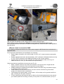
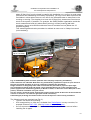
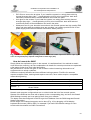
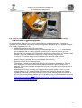
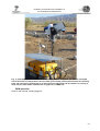
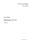
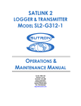
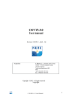
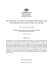
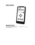
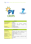
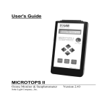
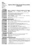
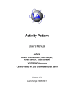
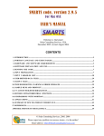
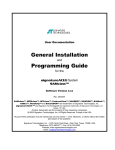
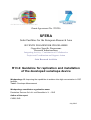
Grant Agreement No. 228296 SFERA Solar Facilities for the European Research Area SEVENTH FRAMEWORK PROGRAMME Capacities Specific Programme Research Infrastructures Integrating Activity - Combination of Collaborative Project and Coordination and Support Action Joint Research Activities R13.2: Guideline for replication and installation of the developed sunshape device Workpackage 13: Improving the capabilities to achieve ultra-high concentration in CSP facilities Task 1: Sunshape Measurement Workpackage coordinator organisation name: Deutsches Zentrum für Luft- und Raumfahrt e.V. – DLR Author of the report CNRS, DLR July 2012 Guideline for replication and installation of the developed sunshape device Table of Contents Introduction to R13.2, Guideline for replication and installation of the developed sunshape device Overview of the Work package 13, TASK 1: Improving the capabilities to achieve ultra-high concentration in CSP facilities — Measurement of the sunshape and evaluation of the impact on concentration Content of this report Description of the measurement system Replication of the CSR measurement system Replication system: PROMES-CNRS Forewords: Visidyne’s Manual Where to get the parts? SAM: what will I receive? What do I need to mount the SAM? How do I mount the SAM? SAM mounting suggested upgrades SAM operation Sunshape and CSR determination SAM net upload tool Installation procedure Obtaining the necessary Aeronet data Preparation of auxiliary meteorological data for the post processing Sunshape post processing software Description of the output files of the sunshape measurement system after the post processing References 3! 3! 3! 3! 3! 7! 7! 7! 7! 9! 10! 12! 13! 14! 15! 15! 15! 16! 19! 19! 20! 21! 2 Guideline for replication and installation of the developed sunshape device Introduction to R13.2, Guideline for replication and installation of the developed sunshape device This report is a delivery of Workpackage 13 Task 1. Overview of the Work package 13, TASK 1: Improving the capabilities to achieve ultra-high concentration in CSP facilities — Measurement of the sunshape and evaluation of the impact on concentration Objectives • A Development of a sunshape measurement and monitor system, that automatically monitors the sunshape at the weather station of a CSP facility and which will serve as master for replication and as a reference for other devices (DLR) • B Second system set-up in sunshape measurement device at CNRS. (CNRS) • C Define impact of the sunshape (Circumsolar Radiation, CSR) on the performance of some existing CSP installations by measurement of flux distribution, enlargement of beam diameter or intercept factor depending on concentrating technology. (DLR, CNRS, WEIZMANN) • D Validation of ray-tracing tools by comparison of flux measurements with ray-tracing predictions based on measured sunshape and high precision geometry data of the heliostat field reflective surface (DLR) • E Derivation of sunshape from Meteosat Second Generation (MSG) satellite observations (DLR) • F Investigation of the influence of sunshape on irradiance measurements (DLR) Content of this report This report is part of objective B, Second system set-up (CNRS) and represents a guideline for replication, installation and use of the developed sunshape measurement device. Description of the measurement system Objective A: Development of a sunshape measurement and monitor system (DLR) At DLR-PSA, a sunshape measurement system was developed. The system uses the commercial instrument SAM (Sun and aureole measurement system) which was designed for the investigation of cloud properties. The previous version of the system [DeVore2009] was analyzed and necessary improvements were identified. As a result of a detailed discussion of the necessary improvements with the manufacturer Visidyne Inc., a new version (SAM 400) was developed by Visidyne. This version features increased calibration accuracy, more precise sun tracking and additional spectral filters. The complete sunshape measurement system consists of the Sun and Aureole Measurement (SAM) instrument, a sun photometer and a post-processing software. The system is fully automated and weather proof (Fig. 1). Both instruments are part of measurement networks and the measurements are available online (SAM: site name “PSA”, http://www.visidyne.com/SAM/SAM_DATA_.htm. Sun photometer: site name “Tabernas_PSADLR”, http://aeronet.gsfc.nasa.gov/cgi-bin/type_one_station_opera_v2_new?site=Tabernas_P SA-DLR&nachal=2&level=1&place_code=10). 3 Guideline for replication and installation of the developed sunshape device Fig. 1: Photo of the SAM Series 400 next to the Cimel sun photometer at DLR's meteorological station at the Plataforma Solar de Almería (PSA). The SAM instrument uses two cameras: one camera for the sun disk and another camera for the aureole. Both cameras are Pixelink PL-A741 CMOS cameras with 25 mm Pentax C-Mount lenses. They are mounted on a solar tracker so that the sun-disk camera is facing the sun directly. The aureole camera takes images of a screen (Fig. 2). A lens forms an image of the aureole on this screen while the rays coming from the sun disk itself fall onto a beam dump. The use of five exposure times per each measurement and camera provides the required high dynamic range whatever the luminosity conditions. Fig. 2: Schematic of the SAM (sun and aureole measurement) instrument. The results of the SAM instrument include a radial average radiance profile which is created using the information from both cameras. There is a gap for most measurements that are relevant for solar power between an angle close to the solar disk angle and 0.475° from center. This is due to the limited dynamic range of disk camera and the size of the beam dump in the screen of 0.375°. The gap is usually bigger than 0.375° because the data close to the border of the beam dump is not reliable due to the roughness of the screen in this region. For high CSR no gap occurs due to the less pronounced step in the radiance profile close to the solar disk angle. The gap is filled with a power law fit after the detection of the appropriate supporting points. The measurement of the disk radiance is used as an upper limit for the resulting fitted radiance, which increases the robustness of the regression. The SAM instrument was designed for the investigation of cloud properties, such as particle optical depth and cloud particle size distribution (Fig. 3) and effective radius [DeVore2009]. Thus, SAM uses narrow band-pass filters. The cameras’ band-pass filters are centered at 670 nm with a full width at half maximum of 10 nm. The filters can be exchanged with filters centered at 440 nm and 870 nm. For these wavelengths, comparison and cross calibration with the Cimel CE 318 [Holben1998] sun photometer is possible. The sun photometer measures spectral direct normal irradiance and spectral sky radiance at nine different wavelengths between 340 nm and 1640 nm. Scattering, and thus the resulting spectral sunshapes, are wavelength dependent. Therefore, the measured absolute spectral radiance profile at 670 nm might be different from the broadband sunshape that is required for CSP applications. The spectral sunshape is thus transformed to obtain the broadband sunshape. This post processing involves the co-located, sun-photometric determination of aerosol properties. 4 Guideline for replication and installation of the developed sunshape device The spectral transformation is based on spectral extraterrestrial radiance profiles, calculations with a clear sky radiative transfer model and a transformation for the forward scattering of light in clouds. The used clear sky radiative transfer model is a slightly modified version of SMARTS 2.9.5 [Gueymard2001]. The input values for the model are for the most part from PSA's cloudscreened Aeronet data (currently at Level 1.5): o spectral aerosol optical depth, o precipitable water, o aerosol single scattering albedo, o asymmetry factor, o atmospheric pressure, o ozone concentration and o aerosol phase function. Also ambient temperature and relative humidity from the co-located meteorological station are used. The modified version of the SMARTS 2.9.5 code can process tuples of user defined values for the single scattering albedo, the asymmetry factor and Angström's wavelength exponents together with the selection of the phase function model. Thus, the solar spectrum and the spectral CSR for pure aerosol scattering are calculated. The transformation includes a further step if clouds masked the sun. Clouds are detected based on the deviation of particle and aerosol optical depth, the temporal variation of the particle optical depth and the monotonicity of the radiance profile. In the case that clouds were detected, the spectral aureole profile is calculated for several wavelengths assuming that the scattering is dominated by diffraction. Fig. 3: Exemplary results from the SAM (31/1/2012, PSA). Aureole radiance as a function of angle and time (top) and particle concentration as a function of particle diameter and time (bottom). If clouds were detected the resulting spectral CSR and spectral sunshapes are calculated using the cloud and aerosol optical depth and the assumption that the cloud scattering occurred above that by aerosol particles. Exemplary results of the direct measurement with SAM and the post-processed broadband sunshape are shown in Fig. 4. 5 Guideline for replication and installation of the developed sunshape device Fig. 4: Exemplary results of the reference system. Direct measurements of the SAM instrument at 670 nm and the broadband sunshapes obtained after the post-processing are shown. In the legend the broadband CSR (CSRBB) is stated. One color represents one measurement. 6 Guideline for replication and installation of the developed sunshape device Replication of the CSR measurement system Replication system: PROMES-CNRS As the sunshape measurement system was defined, and software was programmed, the next step has been the ordering and installation of the measurement system at PROMES-CNRS. The developed software can be applied, and sunshape data can be measured also in France at a different climate. The CSR can also be monitored on the unique set of high concentration facilities available at the laboratory, having thirteen solar furnaces concentrating from 6000 to 16000 suns. Forewords: Visidyne’s Manual This section is intended to complement Visidyne’s manual [Visidyne2012], therefore only supplementary or highlighted information is given here. The SAM manual used was version 05. It should be mentioned that Visidyne also provides service support. Where to get the parts? As described previously, to determine the sunshape you need a SAM device and a Cimel sun photometer (Aeronet) for the determination of the spectral aerosol contributions. • SAM Hardware provider: Visidyne 99 South Bedford St. Suite 107 Burlington, MA 01803 USA Telephone: 781-273-2820 Fax: 781-272-1068 http://www.visidyne.com/ The system is normally provided with one installed set of filters at 670 nm, but you can order a supplementary wavelength calibrated filters at 870 nm and 440 nm: in that case you manually mount and unmount the selected filters inside the head. For the standard application and standard sunshape measuements the filter at 670 nm is sufficient and recommended. • Sunphotometer: the reference system is available from Cimel: Cimel 172, rue de Charonne 75011 Paris France Telephone: +33.01.43.48.79.33 Fax: +33.01.43.48.62.61 http://www.cimel.fr/ The recommended instrument is Cimel CE-318N EBS9 sun photometer. Also other versions of the instrument are possible without drawbacks if these instrument versions are allowed in the Aeronet.: The instrument is delivered including its own programmed tracker and it is not possible to install the sensor on another tracker. Instrument details: http://www.cimel.fr/photo/sunph_us.htm ⚠ The sunphotometer requires periodic calibration as its filters age. Participation to the Aeronet network is advised if possible to contribute the data and benefit from the calibration services. Also Aeronet provides the post processing of the sun photometric measurements which are necessary to obtain the desired input for the software that calculates the broadband sunshape and which is described later in this document. The 7 Guideline for replication and installation of the developed sunshape device • • required input format for this software is currently the one used by Aeronet. If no sun photometer is available near the site where the SAM is positioned, further options for obtaining additional required information on aerosols can be considered: i. Calculations with SMARTS2 based on estimations or non Aeronet ground and satellite measurements.. The SMARTS code is developed by Chris Gueymard to accurately simulate notably the ground solar spectrum from UV to near IR: Solar Consulting Services [email protected] http://www.solarconsultingservices.com/ Code details: http://www.solarconsultingservices.com/smarts.php Download: http://www.nrel.gov/rredc/smarts/ One option for non Aeronet ground measurements is given by spectrometric measurements of DNI. An Ocean Optics USB 2000 is proposed by Visidyne. This option includes integration into the head and all the required optical components and testing. Spectral range covered is 200 – 1100 nm. Instrument details: http://www.oceanoptics.com/products/usb2000.asp The spectral aerosol optical depth can be retrieved from these measurements and thus part of the input which is usually included in the Aeronet files can be provided. You also need a ground weather station to get measurements of the following data: o Air measurements: temperature, relative humidity, pressure. o Solar measurements: DNI, GHI, DHI (not required to have both GHI and DHI, but strongly advised for quality control). You can find guidelines to set up weather station with suitable performance in the following existing guidelines: o “Best Practices Handbook for the Collection and Use of Solar Resource Data” by NREL, http://www.nrel.gov/docs/fy10osti/47465.pdf o “Baseline Solar Radiation Network Operation Manual” from WRMC-BSRN is available from the following URL: http://www.wmo.int/pages/prog/gcos/documents/gruanmanuals/WCRP/W CRP21_TD1274_BSRN.pdf For example, for the different stations at PROMES-CNRS, we use Vaisala WXT520 weather transmitters for all the required air measurements (plus wind and precipitations), and solar equipment from Kipp & Zonen or Eppley Laboratories with data acquisition modules from Gantner (see Fig. 6), the rest being standard material with suitable reliability (network devices, communication gateways, online or line interactive UPS, computers…) or custom made (Java software for data acquisition, data base storage with MySQL, export and access with PHP, Apache and HTML5+Javascript): o Solys 2 and 2AP solar trackers from Kipp & Zonen, ST-3 solar trackers from Eppley Laboratories, CE-318 from Cimel o CH1 and CHP1 pyrheliometers from Kipp & Zonen, NIP pyrheliometers from Eppley Laboratories, CE-183 pyrheliometer from Cimel o CMP11 and CMP21 pyranometers with CV2 ventilation from Kipp & Zonen, PSP pyranometers from Eppley Laboratories o High accuracy and wide temperature compensated data acquisition modules from Gantner, model A4-TC, used for most sun sensors 8 Guideline for replication and installation of the developed sunshape device Eppley Laboratories 12 Sheffield Avenue, PO Box 419 Newport, Rhode Island 02840 USA Telephone: 401-847-1020 Fax: 401-847-1031 [email protected] http://www.eppleylab.com/ Kipp & Zonen (see website for your country contact) [email protected] http://www.kippzonen.com/ Vaisala (see website for your country contact) http://www.vaisala.com/ Gantner Instruments (see website for your country contact) http://www.gantner-instruments.com/ Fig. 6: Two solar stations at CNRS. Odeillo (left) with 2AP solar tracker, CHP1 pyrheliometer (DNI), CMP21 pyranometer with shading and CV2 ventilation unit (DHI), from Kipp & Zonen, PSP pyranometers — one with shading (DHI) and one without (GHI) — from Eppley Laboratories, all sensors acquired by Gantner A4-TC modules in the gray plastic boxes in the background. Thémis / Pégase (right) with Solys 2 solar tracker, CMP11 pyranometers with CVF3 ventilation unit — one with shading (DHI, right) and one without (GHI, left) — from Kipp & Zonen, all sensors including the Vaisala WXT520 for air measurements (not visible) acquired by one Gantner e.reader module in the gray plastic box in the background on right. SAM: what will I receive? Visidyne supplies the SAM in 2 robust military cases (by Pelican) and a box (Fig 7.): • One case (orange) is the control console. • One case (black) with the components to mount: instrument head, FLIR tracking head, cables, printed manual, air pipes, second set of filters if ordered. • One box with the Meade tripod mount. 9 Guideline for replication and installation of the developed sunshape device Fig. 7: SAM parts: all 3 boxes with the black case for the components to mount on foreground (top left), air pipes and manual on the orange control console case (top right) Wires and rain sensor (bottom left), MEADE tripod and FLIR tracking head (bottom right). The instrument head is not shown here (white rectangular box), see the manual or other photos in this document. What do I need to mount the SAM? ⚠ The SAM is designed and built in the USA: power supply is 110 V and all the mechanical is imperial sizes. Environmental specifications (not specified in the manual): • Power supply connection: up to 800 VA @ 110-120 V AC. Actual nominal consumption is lower. • System operation has been demonstrated by -20°C (Visidyne in Massachussets) and up to +35°C (DLR at Almeria, with additional shading of the console system). • Console case should not be put vertically as some components may move (e.g. for ladder access to a roof, you should take extra precautions). Space required (not specified in the manual, see Fig. 8): • About 1 square meter for the head and its tripod on the ground: don’t forget that the head will move to track the Sun and requires a bit more space. • Cables between the head and the console are about 4 meters long; this allows roughly 3 m between both components. • Cable between the rain sensor and the console is about 4 meters long; this allows roughly 3 m between both components. • The console box requires about 120 cm wide x 130 cm deep on the ground and 80 cm high, including the air pipes clearance. • For the scattering measurements with the ball on stick method described in the manual, you need to place this occulting 4 inches (12 cm) ball on its 18 feet tall stick (5,5 m) at 10 Guideline for replication and installation of the developed sunshape device about 25 feet (8 m) from the head: be careful with installation on a roof on its south edge (advised to limit shadowing from nearby equipment), you may not be able to perform the occultation in winter when the sun is too low on the accessible east or west parts in the morning or evening. The simplest is to have this 25 feet (8 m) clearance at noon hence south of the system, if possible. For example, the CNRS Odeillo organization avoid this south measurement and only allows East (morning) or West (evening) ball stick procedure, hence not at Winter solstice as the sun would be too low (below the 10° required degrees). This scattering determination procedure is advised at most once in Visidyne’s manual (not mandatory). Surveillance camera Rain sensor Up to 3 m away Up to 3 m away 80 cm 130 cm 120 cm Fig. 8: CNRS SAM system at Odeillo (Summer 2012 campaign temporary installation). Total clearances are indicated. Note than only extraordinary operations require to open the lid of the case as normal operation is done by controlling remotely the inboard PC. Height clearance is marginally lower with lid closed as the provided air pipes are quite high. The instrument, tracking head and tripod, can be placed at about 3 m on the west like on the picture (right on this south facing picture) or North or South, or about 2 m on the East (left on the picture). Cardinal orientation is at your choice. The rain sensor, below the arrow showing the height, can be placed at about 2 m at most from the console on its left or 3 m from the right (side of the connection). A dead weight (10-20 kg) should be used to secure the tripod in case of windy conditions. The following tools are required (see Fig 9.): • 1 person can do all the mounting. • 3/16 hexagonal key or Allen key. Available from RadioSpares in many countries, for example reference 297-1522, see http://www.rs-components.com/. • 2x2 cm square tool: the caps for the air vents may be a bit difficult to remove before installing the air pipes. 11 Guideline for replication and installation of the developed sunshape device • • • PVC Glue to secure the air pipes. If you install the system in a windy place with big thermal changes (day-night…), hand tightening is likely to be insufficient: both wind induced movements and or thermal dilatation can loosen the parts. Lock glue for the screws. If you install the system in a windy place with big thermal changes (day-night…), hand tightening is likely to be insufficient: both wind induced movements and or thermal dilatation can loosen the parts. Waterproof box for your electrical connections: the console system has high quality IP68 plugs and wires with the suitable plugs are provided, you need to provide a box for the power supply and Ethernet network connections water proofing. Fig. 9: Hand tools required are: possibly a tool for a 2x2 cm female square for the air caps if you can’t do it by hand (left), imperial hexagonal or Allen keys (left) How do I mount the SAM? Simply follow the explications given in the manual, it is well described. It is advised to read it once before the mounting, as some explanations or details for several procedures are explained a few pages further than their initial description. We just advise to use the lock glue on the screws to reduce loosening risks and loss of equipment due to windy conditions. Cables are uniquely identified and have different locking systems: FireWire for cameras requires multiples clicks, tracking head requires one click, other cables require a compatible reasonable tightening. SAM plug Painted white Marked “L” Marked “ ” US norm White Black Green or Green/Yellow EU (IEC) & UK Blue Brown Green/Yellow Description Neutral Live Earth ground Tab. 1: Electric power supply markings and standard wires color. Network and computer configurations are on a label inside the lid of the console system. Startup of the SAM can be done with a laptop on the corresponding plug, and once the firewall WAN settings correctly set it can also be done from your network. The laptop must be configured in DHCP to get its IP address from the SAM integrated firewall (laptop connection). Direct usage of the inboard computer can be done (Fig. 10) by plugging a VGA display, keyboard and mouse (USB or PS2), for example if you have lost network settings or have trouble with the network and VNC connections. 12 Guideline for replication and installation of the developed sunshape device Fig. 10: Direct usage of the inboard computer is possible to troubleshoot network settings. SAM mounting suggested upgrades As provided form Visidyne, the system is well suited for campaign operation. Long-term operation at a fixed place may require hardware upgrades depending on your weather climates. It is notably suggested (Fig. 11): • Additional protection of the console system. Check notably the box temperatures (“Housekeeping” in the slc_init software) and the suitability of the air venting system depending on the amount of dust you have. Electronics and computer don’t like dust nor temperature above 40°C, or it shortens their lifespan. DLR has shaded the console box to help reducing temperatures. In case of cold climate and/or humid climates care has to be taken to avoid condensation from water of ice, as it can lead to short circuits. Appropriate additional heating may be required. Take in consideration wind cooling. • Rigid mount pole for the tracking head. The Meade provided tripod has been designed for astronomy observations. For long time application in harsh outside climate, replacement with a ground fixed pole is advised. Think of the required clearance for the instrument head movements for such a modification. Mounting can be done including the Visidyne white metallic board (3 holes in a 120° triangle pattern of 137 mm long sides, M8 screw can fit through despite the imperial threading) or directly below the FLIR pan & tilt PTU100E tracking head (4 screws in a 85.725 mm square pattern, advised #1/4-20 (Kodak screw), metric compatible should be M6, see user manual at FLIR page 15 http://www.dperception.com/uploadedFiles/Directed_Perception/Documents/Products/P TU-D100/PTU-D100E-Manual.pdf). 13 Guideline for replication and installation of the developed sunshape device Fig. 11: DLR SAM system at PSA, with hardware upgrades for long term operation: a removable roof reduces the box temperatures and a custom ground fixed pole has been built for the tracking head. The rain sensor (left behind) is on the original provided pole and 45° fixation. Air venting is done with the white filters instead of the air pipes as on CNRS unit. !SAM operation Refer to the manual, starting page 34. 14 Guideline for replication and installation of the developed sunshape device Sunshape and CSR determination The determination of the CSR and the sunshape involves several steps. First, the software “autogui” /current version “samnet_auto_gui_400v02.sav”) is used to calculate particulate spectral optical depths (OD) and radial spectral radiance profiles for the corresponding wavelength of the used filter. This software can be set to automatic processing during the night and it is explained in the SAM manual. The required cdf files produced with this application are the OD file (e.g. “401_050311_OD_.cdf”) and the radial radiance file (e.g. “r_401_050311_AP_.cdf”). Then these cdf files have to processed together with additional information on the aerosols. This processing can be done at DLR after uploading the cdf files to a ftp server. For this option an upload tool is available that allows the automatic daily data transfer. Alternatively the data can be processed on a local machine using an executable which can be obtained from DLR. SAM net upload tool If the sunshape post processing software is not installed on the ICC (Instrument Control Computer) the cdf files created by the autogui program have to be sent to the workstation with the post processing software. Also, the idea of the SAM instrument is to be used in a measurement network and to provide the data to the scientific community as it is valuable also for atmospheric science. Thus an upload tool was created to allow the daily transfer of the cdf files to a ftp server. A download tool was programmed, too. When executed the SAMnetUploadTool.exe checks if cdf files are found in a specified folder on the ICC and uploads them to your SAMnet folder, e.g. on "ftp.visidyne.com". After the upload the local files are moved to a specified folder for the uploaded files in your network or on the ICC. The upload activity is logged in "SAMnetUpload.log". Installation procedure 1. Download the file "samnetUploadTool.zip" from "/Samnet/Tabernas_PSADLR/SAMNET_uploadTool" on "ftp.visidyne.com" (e.g. as anonymus user). The zip file contains: -SAMnetUploadTool.ctf (component technology file), -SAMnetUploadTool.exe, -SAMnetUpload.log & -ConfigFileSAMnetUpload.txt 2. Put the content of the zip-file in a folder of your choice on the SAM instrument control PC (The pwd is "samnet".). 3. If no Matlab 7.12.0 executables have been used on the PC so far download and unzip the ten files "Installer.zip.0xx" (pwd “test”). Then run the thus obtained file "MCRInstaller.exe". 4. Open "ConfigFileSAMnetUpload.txt" and enter your user name and your password for your SAMnet folder. Create the folder "AlreadyUploaded" in "C:\Processed_Data\" and make sure that the files you want to upload are stored in the folder specified as Inputfolder (default "C:\Processed_Data"). If you only want to upload certain days of the data in the given input folder specify the interval using the variables "StartDate" and "EndDate". Usually you should set the variables to 'allFiles'. Save "ConfigFileSAMnetUpload.txt". 5. Run "SAMnetUploadTool.exe" to upload the data. If the first run only creates a folder "SAMnetUploadTool_mcr" run it again. 15 Guideline for replication and installation of the developed sunshape device 6. If this works you should see that day-folders are created in your SAMnet directory on Visidyne's ftp site and that cdf files are uploaded to these folders. The local files should be moved to the local folder "AlreadyUploaded" (or the nondefault folder you specified in the config-file. 7. Define a "Scheduled Task" in the "Windows Control Panel" that calls "SAMnetUploadTool.exe" daily some hours after the automatic processing of the SAM data. Obtaining the necessary Aeronet data The required information on atmospheric aerosols can be optioned from Aeronet stations. The data for the stations is available online under specified conditions of use. For PSA the URL is: http://aeronet.gsfc.nasa.gov/cgibin/webtool_opera_v2_inv?stage=3®ion=Europe&state=Spain&site=Tabernas_PSA-DLR You can choose the nearest existing station from the page http://aeronet.gsfc.nasa.gov/cgibin/webtool_opera_v2_inv, pay attention to select the station with the most similar climate and human activities if several choices are possible. For example, as there is no data for CNRS in Odeillo (42.497° N and 2.030° E), the nearest Aeronet site is Pic du Midi which is also in the mountains instead of Barcelona which is very industrial and at sea level: http://aeronet.gsfc.nasa.gov/cgibin/webtool_opera_v2_inv?stage=3®ion=Europe&state=France&site=Pic_du_midi Fig. 12: NASA Aeronet 789 existing stations as of June 2012. On this page download level 1.5 or level 2.0 data. On the page for “Version 2 Direct Sun Algorithm” select “Aerosol Optical Depth (AOD) with Precipitable Water and Angström Parameter”, “Instrument Information (e.g., Exact Wavelengths)* Merge with AOD” and “Total Optical Depth with components* ”. Select the required time interval (recommended 1 year for convenient post processing) and download the data. On the page for “Version 2 Inversion Products” select “Phase functions”, and the “Combined File (all products without phase functions)”. Specify the same time interval as before and download the data. The necessary settings are shown in Fig. 13 and Fig. 14. 16 Guideline for replication and installation of the developed sunshape device Fig. 13: Export settings for Aeronet data. Total optical depth and aerosol optical depth file. 17 Guideline for replication and installation of the developed sunshape device Fig. 14: Export settings for Aeronet data. Phase functions and combined file. 18 Guideline for replication and installation of the developed sunshape device Preparation of auxiliary meteorological data for the post processing For the post processing of the SAM and the Aeronet data further meteorological parameters are necessary. The parameters should be provided in a txt file in MESOR format as seen in the example below. The necessary parameters and the corresponding units are • date “YYYY-MM-DD” • time “HH:MM” • GHI global "W/m^2" • DNI direct "W/m^2" • Tamb ambient temperature "°C" • relHum "relative humidity" "%" • p "air pressure" "mbar" Other parameters are optional. The time resolution should be 1min. #MESOR V1.1 11.2007 #type sequenceofRaditionValue #unitName W/m^2, mbar, °C, m/s, °N #valueType Irradiance, pressure, temperature and wind #IPR.providerName XXX #IPR.timeSeriesTitle DLR-PSA-HP 2012 #IPR.copyrightText DLR #location.latitude[ºN]: 24.44176 #location.longitude[ºE]: 54.61661 #location.height[m]: 27 #location.summarizationType 1 min #timezone UTC+1 #comment by Stefan Wilbert and Fabian Wolfertstetter, DLR-PSA #channel date "date" YYYY-MM-DD #channel time "time" HH:MM #channel GHI "global, measured with instrument 0" "W/m^2" #channel DNI "direct" "W/m^2" #channel Tamb "ambient temperature" "°C" #channel relHum "relative humidity" "%" #channel p "air pressure" "mbar" #begindata 2012-02-03 00:00 -0.434999 0.4240957 18.90764 80.78713 2012-02-03 00:05 -0.7146633 0.4240963 18.9662 80.56303 #enddata 1012 1012 Sunshape post processing software The sunshape post processing software written at DLR PSA for the evaluation of the monochromatic radiance profiles allows their conversion to broadband sunshapes, spectral CSRs and broadband CSRs. The processing can be done at DLR-PSA or also on a local machine using an executable. The executable requires Matlab 7.12.0 or the MCRInstaller as described in the section on the SAMnet upload tool in point 3. The executable uses the cdf files, the auxiliary meteorological data and the aeronet data. If no Aeronet data is available also default values or estimated values can be used for the aerosol properties. The paths of these input files and further parameters are set in a configuration file (text, in Matlab syntax). The configuration file is selected in a GUI after the execution of the executable. All necessary settings are described in detail in the configuration files (“SAM2sunshapeNCSR_config.txt” and “configSMARTSMatlabSAM2011.txt”). The functionality of the software is documented in [Wilbert2011]. 19 Guideline for replication and installation of the developed sunshape device Description of the output files of the sunshape measurement system after the post processing The results of the post processing are stored in Matlabs “mat” format. The file names are SAM_”Type””StartDate”-“EndDate”-.mat. The first and the last day of the data contained are given in the files name as “yymmdd”. There are three different output files indicated by “Type”: • “all” contains all the variables used in the postprocessing • “ssd” contains only the most relevant parameters radiance profiles, the CSR, DNI, … and the time (see list below) • “CSR” is very similar to “ssd” but the relative radiance profiles are not included. The structure ssd always contains the following fields solarAzimuth solar azimuth in °N solarAltitude solar elevation angle in ° CSR circumsolar ratio as decimal number (disk angle calculated for the specific time [Liou2002], outer angle maximum of “angles”) PyrhelClear DNI in W/m² as measured by your pyrheliometer PyraHorzClear GHI in W/m² as calculated from the above DNI and a DHI measurement (the name is selected to fit to the LBL RDB (reduced database)) UTCnumeric time and date for all parameters in UTC in Matlabs numeric time format (serial date number in days counted from a specific date and time (Jan-10000 00:00:00 corresponds to the number 1) solarTime solar time for all parameters in hh:mm:ss CloudPresenceVec vector with 1 for measurements when clouds were detected, 0 for clear sky sunshapes (In files created before June 1st 2012 this is only contained as a variable in the “all” dataset.) name name of the dataset In the “ssd” and “all” mat files two more fields are found: angles angular distance from the center of the sun for the radiance profile in ° relRad relative radiance (unitless) for the angles specified in “angles” The most relevant parameters from the “all” mat files are: AM_SAM CSR_spectral the air mass for the times in “ssd.UTCnumeric” the spectral CSR for the wavelengthsintervals given in SmartsExt. Wvlgth SmartsExt.Wvlgth LambdaSAM DiskAngleDegr r2sun tauSAM tauAero tauCloud wavelength used for the spectral CSR in nm wavelength of the filters used in the SAM instrument in nm used diskangle for each measurement in ° (as always half angle) distance between the sun and the earth in m for each measurement Particulate optical depth for the SAM filter wavelength Aerosol optical depth for the SAM filter wavelength calculated as an interpolation from the Aeronet data Cloud optical depth for the SAM filter wavelength calculated from tauAero and the particulate optical depth measured with the SAM instrument 20 Guideline for replication and installation of the developed sunshape device References [DeVore2009] DeVore, J., Stair, A., LePage, A., Rall, D., Atkinson, J., Villanucci, D., Rappaport, S., Joss, P., and McClatchey, R., 2009, "Retrieving Properties of Thin Clouds From Solar Aureole Measurements", Journal of Atmospheric and Oceanic Technology, 26, pp. 2531-2548. [Visidyne2012] Manual for the SAM instrument, version 5, 2012. [Gueymard2001] Gueymard, C. A., 2001, "Parameterized transmittance model for direct beam and circumsolar spectral irradiance," Solar Energy, 71(5), pp. 325-346. [Liou2002] KN Liou. An introduction to atmospheric radiation. Academic Press, 2002. [Wilbert2011] Wilbert, S., Reinhardt, B., DeVore, J., Röger, M., Pitz-Paal, R., and Gueymard, C., 2011, "Measurement of solar radiance profiles with the sun and aureole measurement system (SAM)", SolarPACES Granada. (also submitted to Journal of Solar Energy Engineering). 21