1
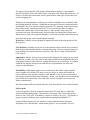
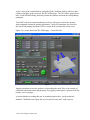
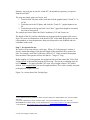
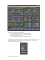
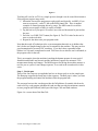
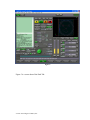
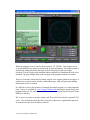
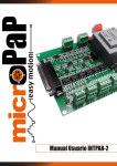
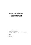
The MachStdMill project: Customizing CNC Control Software. Part 1 By David Bagby, Calypso Ventures, Inc. There’s a hole in the bucket Dear Liza, Dear Liza 1…. Personal CNC machines commonly use PC based hardware and software to control machine motion. Several software packages are available which offer PC based CNC operation. The control software runs G-Code programs to create the corresponding machine motion. CNC software also provides the user interface for the machine’s operator. I had been using the Mach3 2 CNC control software and I’d started thinking about ways the default Mach user interface was impeding my CNC projects. Knowing that Mach supports user customization, my initial musing progressed to jotting notes, morphed into screen page layout sketches, and eventually became a user interface (UI) re-design specification. It looked good on paper… and like other “little” projects, this one grew into more than was originally anticipated. By the time you read this in print, close to 2 years will have passed since the initial thoughts… but I now think the hole in the bucket has been nicely patched! This series of articles is intended to illustrate the degree to which Mach can be customized, and to describe techniques you can use to create your own modifications. I’ll be using examples from the MSM project to illustrate various ways Mach can be customized. If you prefer not to “roll your own” software, the results of the MSM project are available via a software enhancement package for Mach3: MachStdMill (abbreviated as MSM). This project article is divided into three parts: Part 1 covers the project’s major design goals and the user interface (UI) principles used for the screen designs. Part 2 describes the extended functionality developed during the project and how it integrates into the UI design to make the CNC operator’s tasks easier. Part 3 will delve into the script programming extensions added to Mach to support the needs of the project 3. User Interface Design 1 From a folk song which dates back to around 1700. Mach3 is a CNC control software product from Artsoft USA. In this article it is referred to by the generic term “Mach”. 3 I was able to work with ArtSoft to extend Mach’s script capabilities to address the project’s needs. My thanks to Brian Barker of ArtSoft USA for his supporting efforts. 2 © 2011-2012 Calypso Ventures, Inc. The impact of user interface (UI) design is often under recognized. A good human interface facilitates your work, while a bad UI can make even simple tasks laborious. UI design is all about user interaction, and it’s good to know what types of tasks and users you are designing for. During the investigation phase of the project, I talked with Mach users to identify what they thought about the software. I found that the opinions fell into two broad categories: a) Industrial CNC users who have added a personal CNC capability to their home shops (these folks tend to want the personal CNC UI to act exactly the same as whatever commercial machine they were already used to), and b) people whose only CNC experience has been with Mach (many of these people were unsatisfied with the stock Mach screen set and were trying out alternative screen sets created by other Mach users). From the latter group, some common themes emerged: Work flow: Controls were not grouped to support the order of the steps people use for their projects. UI Consistency: Existing screen sets were inconsistent re how controls were presented (both in style and function) and this was hampering usage. This was strongly expressed by new Mach users who did not have experience with “how it’s done on an industrial CNC control”. Appearance: Mach’s stock screens were not really designed; they simply grew in an adhoc fashion over the years. The visual result is that controls are misaligned and the color and graphics schemes make it hard to visually find objects on a screen page. A common comment was that the red/green use made the screens problematic for users with red/green color blindness. Extensibility: While Mach supports user customization, the ability requires that the source graphics be available. For many screen sets, these are either not available or require software tools which are expensive and demand a level of user expertise that is not common within the Mach user community. When a user did find a screen set that did part of what they wanted, they were often stuck, as lack of graphics sources prevent further customization. My conversations with users helped make the “hole in the bucket” more clearly defined. Project goals: As more people have become interested in personal CNC tools, they’re often folks without machinist backgrounds. Their interests in personal CNC tools are driven by a desire to “use a CNC tool” more than by a desire to “build a CNC tool”. This became a group of people I decided to keep in mind when designing MachStdMill’s UI. It appeared that an improved user interface, coupled with the enhancement and integration of key functionality, would enable people to “use a personal CNC tool”. © 2011-2012 Calypso Ventures, Inc. Accordingly, these became the design goals for the project: Work flow: The primary screen pages would mirror the common work flow steps people were already using. The number of primary usage pages would be limited in accordance with known UI and human factor principles. Four pages cover normal usage of Mach and three others provide support for secondary (setup, configuration and diagnostic) functions. Context sensitivity would be used to show the operator information when it was needed. This would help to mitigate limitations imposed by what can fit on a single screen page. UI Consistency: Controls would be consistent. Buttons would look like buttons, numeric displays like displays and status indicators like lights/LEDs. There would be no oddities such as “look here, if you click this LED in the upper right corner it brings up this special function”. All features and controls would be documented. Appearance: Form follows function. The appearance must support the requirements of operation of a CNC control. Screen Graphics were to be a tool, not the end goal. Graphics should not be allowed to detract from the presentation of information to the operator. Animation and flashing were to be used only when it was really desired to catch the human eye and only when the operational situation required it. Color schemes would avoid red/green combinations to better support color blind users (this was also considered a way to enhance operation safety). Colors would be used consistently. Functionality: Goals were set for the enhanced functionality for the package: Make job setup operations easy. This goal drove the integration of touch plate support and an extensive set of probing operations. Integration into the package would make UI operation consistent. With this integrated, it would be easy to set Work Coordinates Offsets. Reduce the tasks of the “human tool changer”. Features would be included to make tool handling easier. Automatic measurement of tools during a tool change was desired. Basic part inspection. Support for basic on-machine part measurements would be included. Full User Documentation. All functions would be documented. The user documentation for a feature was often written and circulated for comment before the corresponding code was implemented. The resulting user manual is extensive and is regularly the source of complimentary user comments. © 2011-2012 Calypso Ventures, Inc. Quality code. Code was to be of professional quality, including robust run time error handling. Extensibility: The package would be extensible (customizable) using readily available, low cost software tools. The tools picked should not require a large learning investment prior to effective use. Basic graphic objects would be provided so users can easily add common custom controls (e.g. buttons and readouts). Most Mach users don’t want to make complicated customizations. The most prevalent need is to add one button for a special hardware widget and to have a place to put it. Thus, the MSM screens include a “user extensions” page which is “empty” except for the common page controls (jogging, MDI, status displays). Leverage the new Mach script extensions to provide well defined, modular event interfaces. Using the new scripting features, users can supply script code which is called for key events. This is accomplished without the user needing to modify any MSM scripts. Design Non-Goals: It was also important to know what the project was not trying to accomplish. One significant item on the project’s “non-goal” list was touch screen support. Touch screens cost more for a given size screen. This tends to make the touch screens in use smaller while finger sizes don’t magically scale with screen size. Explicit support for touch screens would mandate an entirely different tradeoff between number of pages and the page content partitioning. The project decision was to try to avoid doing anything which would preclude touch screen operation, but this desire would not compromise regular screen features. Design Framework: Months were spent putting the ingredients in the pot, cooking and stirring. Let’s see what resulted… The “Four Steps”: There turned out to be four key steps that most users followed to make a part. The order of the steps is pretty well determined by common sense and G-Code semantics. When presented with these as a logical order, the reaction was usually “That’s what I was looking for”. To illustrate the steps, we’ll use an example where we make a sample part and we’ll see how these steps drive the primary screen page contents. The four core steps are: 1. Load the G-Code program to run © 2011-2012 Calypso Ventures, Inc. 2. Locate the part within the stock 3. Setup the tools needed 4. Cut out the part This sounds obvious, but if the appropriate controls are not at hand for each step, CNC operation becomes inconvenient. The first four pages of the screen set support the “Four Steps”. Step 1 - Load G-Code: Since this is the first step of the process, this is also the page presented when MSM starts. The controls on this page enable the operator to reference the machine, load gcode, jog the machine, simulate the program to check it for errors, and find the extents of the program. Figure 1 is a screen shot of the load page. Figure 1 Step 2 - Locate the part The machine needs to know where the part is within the work envelope of the machine. This is done by telling the machine where the Work Coordinate origin point is – i.e. where “Zero” is for the part. © 2011-2012 Calypso Ventures, Inc. A part’s zero point is established by setting the Work Coordinate Offsets, which is done on the second page in the screen set: the WC Offsets page. The WC Offsets page has two tabs: Touch Off and Probing; Each tab presents the controls used with the corresponding techniques. Touch Off is the most common technique used (it is also more work for the operator when compared to using the probing operations). Touch Off techniques are covered in this article and probing operations will be covered in the second article of the series. Figure 2 is a screen shot of the WC Offset page – Touch Off tab: Figure 2 Jogging operations are used to position a tool touching the stock. Here is an example of consistent control placement and grouping: The jogging control panel is present on all the primary screen set pages. A current Mach user reading this may be wondering where they “set the touch tool diameter”. MSM does not require the use of a special “touch tool” with a special © 2011-2012 Calypso Ventures, Inc. diameter. Any tool may be used to “touch off”, the needed tool geometry is acquired from the tool table 4. The steps are simple, pick a tool to use, and 1. Touch it to the YZ plane of the stock and click the graphic button “Touch X+” to set X0. 2. Touch the tool to the XZ plane, and click the “Touch Y+” graphic button to set Y0. 3. Touch the tool to the top and click “Set Z Zero” (gage block height is accounted for if one is being used). The control now knows where the Work Coordinate’s X,Y and Z zeros are. The details of the WC position calculation are presented in the top panel of the screen. New CNC users are often unsure of the details of WC offset math. Being able to see the offset numbers as a touch operation is done provides positive user feedback and user confidence in the result. Step 3 - Set up tools for use We need to set up some tools to cut the part. When a G-Code program is written, it doesn’t contain knowledge of the physical length of the tools that will be used at run time. For example, while the G-code may call for a 3/8” 2 flute end mill, the program does not know if the operator will use one that is 1” long or 2” long. Before running a G-Code program, the operator needs to tell the control the TLOs (Tool Length Offset) of the tools the program will be using. This can be a confusing topic for new CNC users 5. For many personal CNC users, a key insight is that a CNC control deals in Tool Length Offsets, not in tool lengths and that a TLO value is usually not equal to the physical length of the tool. Figure 3 is a screen shot of the Tooling Page: 4 This is different from stock Mach v3 and is consistent with how I understand the next versions of Mach will work. 5 There are explanations of TLOs available online . Two good explanation of the topic are 1) the MachStdMill user manual which you can download from www.CalypsoVentures.com and 2) Peter Smid’s “CNC handbook” http://books.google.com/books?id=JNnQ8r5merMC&printsec=frontcover © 2011-2012 Calypso Ventures, Inc. Figure 3 This page provides all the controls needed to o See tool information for the current tool and the next tool. o Browse the tool table and edit tool geometry and attributes. o Dynamically handle tool changes. o Select and control MSM’s advanced tool handling features. The technique of touching off of tools to the part’s top surface to set the TLO value is a common industry practice which is also used in the Personal CNC world. We cover support for the technique in this article. © 2011-2012 Calypso Ventures, Inc. Figure 4 Touching off a tool to set TLO is a simple process (though it can be come labor intensive if the program requires many tools). 1. Mount the first tool the program uses (physically and logically via MDI). If you want to set up tool 1, enter T1 M6 on the MDI control line. Here is another example of control grouping driven by usage: The MDI control is on all the primary screen pages so that it is readily available. 2. Jog the tool over your part’s Z0 surface, move the tool down until it just touches the part. 3. Press the “set G-Blk TLO” button (See figure 4). The TLO value for the tool is now set in the tool table. 4. Repeat for the other tools your program needs. Note that the touch off technique relies on an assumption that tools are in holders that don’t let the tool length change as the tool is mounted in the machine. This may not be a good assumption for personal CNC machines. If you don’t have repeatable height holders it is a bit more complicated as each TLO has to be set after the tool is mounted, as the program calls for the tool. This is an example where the machine is making the human operator do extra work. I found this undesirable and it motivated the inclusion of support for automatic TLO measurement during tool changes. The MSM support for having the machine measure a tool for you as a part of a tool change sequence, is covered in the second article in this series. Step 4 - Cut the part Three of the four steps are accomplished and we are about ready to cut the sample part. The Run page supports the fourth step in the sequence. The Run page is where you start the program running and control the machine while the program runs. The run page has two tabs, one that provides the full plethora of controls which can be used to run a g-code program (the Run tab) and one that provides the minimum controls to run a program (the Path tab) which provides larger Code and Path windows. Figure 4 is a screen shot of the Run Tab: © 2011-2012 Calypso Ventures, Inc. Figure 5 Figure 5 is a screen shot of the Path Tab: © 2011-2012 Calypso Ventures, Inc. Figure 6 When the program is run, it asks for the first tool (a 3/8” 2fl EM). Tool changes are an event when MSM uses context to dynamically present information. The displayed page is dynamically changed from the Run page to the tooling page for the tool change operation. The tool is physically mounted and the operator tells Mach that the tool is now mounted. The page changes back to the run page as the program continues execution. This use of run time context allows tooling controls to be separated from the run pages. It enables fewer controls on the already crowded Run page, while still presenting tooling information when it is needed. It’s difficult to convey the dynamics of running the sample program via a static magazine page. Videos are available at www.CalypsoVentures.com showing the sample happy face program being run. The video medium is better for illustrating the dynamic aspects of the MSM user interface. We’ve now seen a part cut using a simple work flow which feels natural to personal CNC users. User feedback has been that the overall user experience is significantly improved in comparison to the stock Mach user interface. © 2011-2012 Calypso Ventures, Inc. The user interface changes provided by MSM demonstrate the customization level that is possible with Mach. In the second article of the series, I’ll look at how integrated support for probing operations can make setup tasks go from complicated to simple. We’ll also explore how tool handling can be enhanced, and how automated TLO measurements can simplify tool change tasks for the personal CNC operator. In the third article of the series, we’ll lift the hood and see how the extended Mach scripting features were used in MSM to implement system functionality extensions. Correspondence about this article may be emailed to the author via [email protected] and the features described within this article are available in the Personal Edition of MachStdMill, available from www.Calypsoventures.com © 2011-2012 Calypso Ventures, Inc.