1
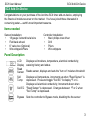
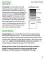
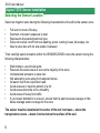
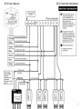
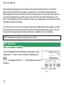
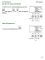
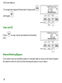
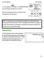
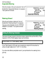
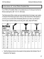
HelpAndManual_unregistered_evaluation_copy
SCX User Manual
ACC-SYS-000X
Digital TDT® Soil Moisture Sensor Irrigation
Timer Add-on Device
Table of Contents
SCX Add-On Device
View .........................................................14
soil EC
3 Manual
.........................................................14
Items needed
.........................................................3 Watering/Bypass
.........................................................15
History
Panel Description
.........................................................3 Watering
Suspended
How it .........................................................4
Works
Watering
.........................................................16
Basic Irrigation Principles
4
Field Capacity
.........................................................5
Watering
.........................................................16
Allowed
Setting the Watering Schedule
Calculating Field
Digitat TDT® Sensor Installation 6 Capacity/Moisture Threshold
Allowable
.........................................................5
Depletion
16
18
Selecting the
Field Capacity
Sensor.........................................................6
Location
Method
.........................................................18
Sensor.........................................................7
Installation
Automatic "turn on"
SCX Controller Installation
SCX Operation
.........................................................19
Method
10 threshold
20
12 Troubleshooting guide
21
Warranty
Take a moisture
reading
.........................................................12
Set "turn on"
moisture
.........................................................13
threshold
View soil
temperature
.........................................................13
SCX Add-On Device
SCX User Manual
SCX Add-On Device
Congratulations on your purchase of the Acclima SCX timer add-on-device, employing
the finest soil moisture sensor on the market. You have joined those interested in
conserving water— earth's most important resource.
Items needed
Sensor Installation:
•
18 gauge 3-strand burial wire
•
Flat blade shovel
•
6" valve box (Optional)
•
Wire strippers/Pliers
Controller Installation:
•
Med. philips crew driver
•
Drill
•
Pliers
•
Wire strippers
Panel Description
LCD
Display
Read
Sensor
Soil
Temp
Displays soil moisture, temperature, electrical conductivity,
watering history and status
Bypass
Sets the controller to Bypass mode, disabling the the sensor
Reads sensor, displays and sets the "turn on" moisture threshold
Displays soil temperature, increments up when "Read Sensor" is
depressed. Press and toggle "Soil EC" to display ºF or C.
Displays soil electrical conductivity, Increments down when
Soil EC "Read Sensor" is depressed. Changes between ºF or C when
"Soil Temp" is depressed.
3
SCX User Manual
How it Works
The SCX uses an Acclima Digital TDT® Soil Moisture Sensor buried in your lawn to
accurately monitor the Volumetric Water Content of your soil.
The SCX Controller connects to your existing irrigation timer. You program your timer to
water every day. The SCX takes soil moisture readings every 10 minutes. If the water
content of the soil is above the "turn on" threshold for your soil then the SCX will
suspend the irrigation cycle by interrupting the power to your solenoid valves. During the
period where your timer is actively attempting to water, the SCX will prevent watering
until 30 minutes of timer inactivity.
If the water content in the soil is below the "turn on" threshold when your timer begins its
cycle, the SCX allows power to your solenoid valves and all programmed zones will
water. The connection will be maintained for the entire watering cycle and for 30 minutes
thereafter – assuring that all zones receive water – even though the sensor may have
become wet during the watering cycle.
The SCX has provisions to water 2 zones independent of the sensor to accommodate
drought-tolerant planting, cacti, trees, potted plants, etc.
Basic Irrigation Principles
®
Acclima's Digital TDT Soil Moisture Sensor allows you to apply two scientific principles
long used by horticulturists: (1) Soil Field Capacity and (2) Allowable Depletion.
4
SCX User Manual
Basic Irrigation Principles
Field Capacity
Field Capacity is the water a given soil can hold
without percolation to the subsoil. Soil can hold a
significant amount of water without percolation, but
gravitational forces will draw all water exceeding Field
Capacity into the subsoil. Irrigation beyond Field
Capacity is wasteful. Field Capacity is generally
measured as Volumetric Water Content, expressed
as a percentage. A Field Capacity of 25% means
that the water volume in the soil is 25% of the soil
volume. Field Capacities range from about 10% for
coarser sands to over 40% for finer clays. Loamy,
silty soils fall in between these extremes.
Allowable Depletion
Allowable Depletion is the Volumetric Water Content at which vegetation begins to
stress as water is depleted from the soil. The point where the force required to draw
water from the soil begins to affect the physical characteristics of the plant is the lowest
Volumetric Water Content that your plants should be exposed to. At this point your lawn
begins to wilt. Irrigation below Allowable Depletion stresses your vegetation. The
Allowable Depletion for grasses is in the range of 80% of Field Capacity.
Maintaining Volumetric Water Content between Field Capacity and Allowable
Depletion saves water, protects the environment and promotes healthier
landscapes. Your SCX can keep your soil moisture within this range.
5
SCX User Manual
Digitat TDT® Sensor Installation
Selecting the Sensor Location
Select an irrigation zone having the following characteristics; this will be the sensor zone:
•
•
•
•
•
Full sun for most of the day
Southern or western exposure is best
Represents the predominant soil type
Does not receive runoff from car washing, pools, running hoses, driveways, etc
Near a valve box with no side walks in between
Then carefully select a location within the SENSOR ZONE to bury the sensor having the
following characteristics:
•
•
•
•
•
•
•
•
•
Well drained—avoid lows spots
Receives the same hours of sun as the majority of the zone
Unobstructed access to a valve box
Not watered by over-spray from adjacent zones
At least 4 feet from a sprinkler head
Avoid areas at or near the bottom of a hill
Avoid areas where the turf is unhealthy
Avoid areas of heavy foot traffic
If your water distribution is uneven, ensure that the spot receives average or little
below average water coverage for the zone
The sensor must be installed at the center of the turf root mass – where the
transpiration occurs – about 4 inches below the surface of the soil.
6
SCX User Manual
Digitat TDT® Sensor Installation
Sensor Installation
Before you install the sensor make sure that the lawn has been recently watered.
This will ease digging, insure that the grass recovers more quickly, and balance
the first irrigation cycles.
Step1 Use a flat-blade shovel to cut an 18
inch slit about 4 inches deep in the soil. Insert
the sensor into one end of the slit with the top
sensor rod about 3 inches from the surface.
Step 2 Arrange the wires from the sensor in
the slit and close the slit on the sensor by
tromping on either side of the slit.
7
SCX User Manual
Step 3 Pour a five gallon bucket of water
slowly over the sensor installation area.
The sensor comes with 3 feet of wire. You will likely need to splice additional wire in
order to reach the valve box. Use only direct burial 3-wire 18 gauge cable in a
polyethylene sheath from your hardware store or irrigation supplier that is rated for direct
burial applications. It is wise to make the splice in a six-inch wiring box that can be
installed near the sensor. This provides access to the splice and also serves as a
marker for remembering where the sensor is installed.
Step 4 When splicing the wires insure that the
wires are twisted together and then protected
by a wire nut securely screwed onto the
twisted wire. Place the wire nuts into a
grease cap to prevent corrosion of the wire
joint. Close the cover on the grease cap.
8
SCX User Manual
Digitat TDT® Sensor Installation
Step 5 Dig a slit trench from the sensor to the
valve box where the valve is installed that
waters the sensor zone.
Step 6 Push the sensor wires into the bottom
of the slit trench with a stick or other blunt
tool. Run the wires under the lower valve box
side and into the valve box cavity. Close the
trench around the buried wires and tromp
down the turf.
Inside the valve box locate the valve that irrigates the zone where the sensor is installed.
Two wires come out of the solenoid on the valve. One of them is connected to the ‘
common’ wire from your timer. The other is connected to the ‘signal’ wire from your
timer. Remove the grease caps and wire nuts from both connections.
9
SCX User Manual
Step 7 Add the white wire from the sensor to
the common wire connection and replace the
wire nut and grease cap. Separate the
solenoid valve wire from the signal wire to the
timer. Connect the black wire from the sensor
to this solenoid wire and fasten it with a wire
nut. Connect the red wire form the sensor
onto the signal wire running back to your timer
and fasten it with a wire nut. Protect all three
connections with grease caps. Your sensor
installation is now complete.
SCX Controller Installation
Mount the SCX control box next to your irrigation timer – close enough for the cable from
the SCX to reach inside your timer to the terminals where it will be connected. Use the
mounting holes and supplied screws to secure the box to the wall. The mounting holes
are aligned for stud mounting if a stud is nearby.
NOTE: Unplug the power to your timer before attempting to wire the SCX control box.
Run the SCX cable into the timer box. Disconnect the common wires going out to your
valves from the common terminal in your timer. Connect the black wire from the SCX to
the common terminal. Connect the white wire from the SCX to the common wires going
out to the valves and secure the connection with a wire nut.
10
SCX User Manual
SCX Controller Installation
11
SCX User Manual
Disconnect the signal wire to the Sensor Zone from the terminal block. Connect the
green wire from the SCX to the sensor zone terminal. Connect the removed Sensor
Zone signal wire to the red wire from the SCX and secure the connection with a wire nut.
Connect the orange wire from the SCX to one of the two 24 volt AC terminals on your
timer. If the display on the SCX comes on when you re-apply power to the timer you have
selected the correct terminals.
If you intend to use one or two zones as timed zones independent of the sensor, connect
the blue and brown wires from the SCX to the terminals that water those zones. Do not
disconnect the valve wires from those terminals. Installation is now complete.
NOTE: Remember to plug in the power to your timer.
SCX Operation
Take a moisture reading
The SCX displays the last moisture reading (taken every
10 minutes). To take a current moisture reading press
. The display will show "- - - " then display the current
moisture.
12
SCX Operation
SCX User Manual
Set "turn on" moisture threshold
To set the "turn on" moisture threshold press and hold
then toggle the
threshold.
or
button to change the
View soil temperature
To view the soil temperature press
.
13
SCX User Manual
To change from degrees Fahrenheit to Celsius hold
and toggle
.
View soil EC
Press
(EC).
to view current soil electrical Conductivity
Manual Watering/Bypass
If you wish to test your sprinkler system or manually water a zone you will need to bypass
the sensor function so that it will not interruupt the power to your valves.
14
SCX User Manual
SCX Operation
To do this press the
button. The ‘SENSOR BYPASS’
icon on the display will slowly turn on and off.
While in this mode actions from your timer will not be
inhibited by the SCX control box.
NOTE: Your system will run any programs without restriction, and can start manual
watering cycles without intervention. When in the Bypass Sensor Mode if you happen to
leave this mode running for several days you will greatly over-water your property since
you likely have set your timer to run daily.
Watering History
The SCX displays the past 7 watering attempts. If
the controller allowed watering a drop is displayed, if
the system was suspended it will be blank. "Today"
indicates the most current watering cycle. The
history updates 30 minutes after each cycle.
15
SCX User Manual
Suspended Watering
When the moisture in the soil is above the "turn on"
threshold the "Suspended Watering" icon appears.
Your system will not water.
Watering Allowed
When the soil moisture is below the "turn on"
threshold the "Watering Allowed" icon appears.
This icon is also displayed when the " BYPASS
SENSOR" is activated. Your system will allow
watering.
Setting the Watering Schedule
The amount of water required to bring the moisture content of the soil from 80% of Field
Capacity to 100% of Field Capacity is given by the formula:
Inches of water = 0.2 * Field Capacity * depth
If your Field Capacity is 25% and you are watering to a depth of 8 inches then the
amount of water needed is 0.2 * 0.25 * 8 = 0.4 inches.
If you know the effective precipitation rate of your sprinklers then the watering time is
given by:
16
SCX User Manual
Setting the Watering Schedule
Run time minutes = 60 * Inches / Effective Precipitation Rate
If your Effective Precipitation Rate for the example above is 0.5 inches per hour then the
Minutes watering time is 60 * 0.4 / 0.5 = 48 minutes.
The following chart offers a simple way to set watering times for all zones in your system.
It is based on the formulas given above. After you have measured the Field Capacity of
your soil you can use the chart to find watering times for your zones. You will need to
know the type of sprinkler heads you are using (rotor, spray, impact, MP rotator).
· Total Run Minutes is total run time required to bring moisture from indicated "turn on"
threshold to Field Capacity
17
SCX User Manual
· Soak Time Run Maximum is minutes allowed before surface accumulation causes
runoff.
· Soak Time Soak Minimum is minutes of soaking required to absorb surface
accumulation.
· Match your zone sprinkler head type and Field Capacity. If your pop-up sprayer zone
has 33% Field Capacity and your "turn on" threshold is 25%, your total run time is 23
minutes. Set your controller to irrigate a total of 23 minutes using a soak cycle with a
maximum “on” time of 7 minutes and a minimum “soak” time of 28 minutes.
This Guide assumes your irrigation distribution system is properly installed and
balanced, operating between 50 and 70 psi in calm wind conditions. Adjustment to your
sensor threshold setting or irrigation total run time, soak run time maximum or soak time
minimum may be required to fine-tune your particular system. If brown appears in your
lawn, have your irrigation maintenance contractor audit your sprinkler system and make
distribution adjustments to uniformly irrigate your lawn.
Calculating Field Capacity/Moisture Threshold
Each lawn is different. Your field capacity and "turn on" moisture threshold are unique.
The following is the best method to determine your ideal moisture setting. Remember
you can adjust your "turn on" threshold at any time.
Field Capacity Method
Near sundown, soak the soil to saturation in the area of the sensor. It is important that
the area is very wet so that the water is standing on the surface. This can be
accomplished with a 5 gallon bucket of water or a garden hose. The next morning
before the direct sunlight reaches the sensor location, take a moisture reading by
pressing the "Read Sensor" button. This reading is your soil's field capacity.
18
Calculating Field Capacity/Moisture Threshold
SCX User Manual
Your ideal moisture level should be 80% of field capacity. Use the table below to
determine your moisture threshold setting.
Field Capacity
10% 15%
20%
25%
30%
35%
40%
45%
"Turn on" Moisture
Threshold
8%
16%
20%
24%
28%
32%
38%
12%
Automatic "turn on" threshold Method
Near sundown, soak the soil around the sensor to
saturation with a 5 gallon bucket or garden hose. Set your
timers to irrigation at 5:00am the following morning.
Finally, simultaneously press and hold both the READ
SENSOR and SOIL TEMP buttons while you depress and
release the SOIL EC button once.
When your timer attempts to irrigation the following morning, the controller will take a
measurement and automatically set your "turn on" threshold to 80% of field capacity.
NOTE: Be sure to re-set your timer later to irrigated as desired and to program the
proper run-time based on your field capacity.
19
SCX User Manual
Troubleshooting guide
Potential Problem
Possible Solution
The SCX display does not come on.
Insure that the power to your timer is on. Insure
that the black wire from the SCX is connected
to the common terminal in your timer and that
the orange wire is connected to the ‘hot’ wire of
the 24 volt ac input to your timer. Try
connecting the orange wire to the other 24 volt
ac terminal. Make sure that your common wire
is not interrupted by an external rain switch.
The SCX does not display a sensor
reading after I press the ‘Set’ button.
The wiring in the valve box or at the timer is
not correct. Insure that the red wire from the
sensor has a wiring path all the way to the red
wire in the SCX cable and that the white wire
from the sensor has a wire path all the way to
the white wire in the SCX cable. No other
wires should be connected to the red wire
connections. The white wire should be
connected to the common wiring for all the
valves. Insure that the common wiring is not
broken and that the insulation on the
underground wiring is not defective.
20
Troubleshooting guide
SCX User Manual
Potential Problem
Possible Solution
The SCX display ‘suspended’ icon
does not come on when the sensor
reading is above the threshold setting.
OR The ‘allowed’ icon does not come
on when the sensor reading is below
the threshold setting.
The ‘suspended’ and ‘allowed’ states will not
change during a watering cycle or for 30
minutes thereafter. Any changes made to
threshold settings during a watering cycle will
not take effect until 30 minutes after the
present cycle has finished. If you need to have
it otherwise you will need to disconnect power
from the SCX by disconnecting the orange
wire. Then upon reconnecting it the new states
will take effect.
One or more of my zones does not get If you have time gaps in your Timer Program
watered during a watering cycle.
that exceed 30 minutes the SCX will suspend
watering after the sensor gets watered and
after a 30 minute inactivity gap. Make sure that
when using cycle and soak features in your
timer that the water is not turned off for more
than 29 minutes.
Warranty
Your controller is warranted for THREE YEARS from date of purchase to be free of
defective materials and workmanship provided it is used within the working specifications
for which the product was designed and under normal use and service. Unless installed
by an authorized Acclima trained technician, Acclima assumes no responsibility for
installation. Acclima also assumes no responsibility for removal or unauthorized repair.
21
SCX User Manual
Acclima's liability under this warranty is limited solely to replacement or repair of
defective parts, and Acclima will not be liable for any crop or other consequential
damages resulting from any defects in design or breach of warranty. THIS WARRANTY
IS EXPRESSLY IN LIEU OF ALL OTHER WARRANTIES, EXPRESS OR IMPLIED,
INCLUDING THE WARRANTIES OF MERCHANTABILITY AND FITNESS FOR
PARTICULAR PURPOSES and of all other obligations or liabilities of manufacturer. No
agent, employee or representative of the manufacturer has authority to waive, alter or
add to the provisions of warranty, nor to make representations or warranty not contained
herein.
22
HelpAndManual_unregistered_evaluation_copy
2260 East Commercial Street
Meridian, Idaho 83642
www.acclima.com
call toll free: 866-887-1470 for service
© 2007 Acclima, Inc.
Acclima, Inc.
2260 E Commercial St
Meridian, ID 83642
SCX User Manual Rev 5 12/12/2007