1
1302 AC Drive
(575V AC)
Version 3.1
User
Manual
Important User Information
Solid state equipment has operational characteristics differing from
those of electromechanical equipment. “Safety Guidelines for the
Application, Installation and Maintenance of Solid State Controls”
(Publication SGI-1.1) describes some important differences between
solid state equipment and hard–wired electromechanical devices.
Because of this difference, and also because of the wide variety of
uses for solid state equipment, all persons responsible for applying
this equipment must satisfy themselves that each intended
application of this equipment is acceptable.
In no event will the Allen-Bradley Company be responsible or liable
for indirect or consequential damages resulting from the use or
application of this equipment.
The examples and diagrams in this manual are included solely for
illustrative purposes. Because of the many variables and
requirements associated with any particular installation, the
Allen-Bradley Company cannot assume responsibility or liability for
actual use based on the examples and diagrams.
No patent liability is assumed by Allen-Bradley Company with
respect to use of information, circuits, equipment, or software
described in this manual.
Reproduction of the contents of this manual, in whole or in part,
without written permission of the Allen-Bradley Company is
prohibited.
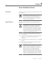
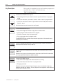
Throughout this manual we use notes to make you aware of safety
considerations.
!
ATTENTION: Identifies information about practices
or circumstances that can lead to personal injury or
death, property damage, or economic loss.
Attentions help you:
• identify a hazard
• avoid the hazard
• recognize the consequences
Important: Identifies information that is especially important for
successful application and understanding of the product.
SCANport is a trademark of Allen-Bradley Company, Inc.
PLC is a registered trademark of Allen-Bradley Company, Inc.
COLOR-KEYED is a registered trademark of Thomas & Betts Corporation
Taptite is a registered trademark of Research Engineering and Manufacturing, Inc.
Table of Contents
Introduction
Chapter 1
Manual Objectives . . . . . . . . . . . . . . . . . . . . . . . . . . . . . . . . . . . .
Drive Description
Chapter 2
Introduction . . . . . . . . . . . . . . . . . . . . . . . . . . . . . . . . . . . . . . . . .
Standard Features . . . . . . . . . . . . . . . . . . . . . . . . . . . . . . . . . . . .
Drive Description . . . . . . . . . . . . . . . . . . . . . . . . . . . . . . . . . . . . .
System Diagram . . . . . . . . . . . . . . . . . . . . . . . . . . . . . . . . . . . . .
Model Numbers . . . . . . . . . . . . . . . . . . . . . . . . . . . . . . . . . . . . . .
Enclosure Ratings . . . . . . . . . . . . . . . . . . . . . . . . . . . . . . . . . . . .
Component Locations . . . . . . . . . . . . . . . . . . . . . . . . . . . . . . . . .
Option Kits . . . . . . . . . . . . . . . . . . . . . . . . . . . . . . . . . . . . . . . . .
Preinstallation
3-1
3-2
3-4
3-4
3-7
3-8
3-9
Chapter 4
Introduction . . . . . . . . . . . . . . . . . . . . . . . . . . . . . . . . . . . . . . . . .
Mounting the Drive . . . . . . . . . . . . . . . . . . . . . . . . . . . . . . . . . . . .
Routing Wires . . . . . . . . . . . . . . . . . . . . . . . . . . . . . . . . . . . . . . .
External Component Installation . . . . . . . . . . . . . . . . . . . . . . . . . .
Setting the Analog Input Jumper on the Regulator Board . . . . . . . . .
Motor Preparation . . . . . . . . . . . . . . . . . . . . . . . . . . . . . . . . . . . .
Drive Wiring
2-1
2-1
2-2
2-3
2-6
2-7
2-7
2-7
Chapter 3
General . . . . . . . . . . . . . . . . . . . . . . . . . . . . . . . . . . . . . . . . . . .
Site Requirements . . . . . . . . . . . . . . . . . . . . . . . . . . . . . . . . . . . .
Cooling Airflow . . . . . . . . . . . . . . . . . . . . . . . . . . . . . . . . . . . . . .
Wiring Requirements . . . . . . . . . . . . . . . . . . . . . . . . . . . . . . . . . .
Input Fusing . . . . . . . . . . . . . . . . . . . . . . . . . . . . . . . . . . . . . . . .
Emergency Stop Installation . . . . . . . . . . . . . . . . . . . . . . . . . . . . .
Motor Considerations . . . . . . . . . . . . . . . . . . . . . . . . . . . . . . . . . .
Installation
1-1
4-1
4-1
4-1
4-4
4-6
4-5
Chapter 5
Introduction . . . . . . . . . . . . . . . . . . . . . . . . . . . . . . . . . . . . . . . . .
Signal and Control Wiring . . . . . . . . . . . . . . . . . . . . . . . . . . . . . . .
Digital Input Wiring . . . . . . . . . . . . . . . . . . . . . . . . . . . . . . . . . . . .
Output Power Wiring . . . . . . . . . . . . . . . . . . . . . . . . . . . . . . . . . .
Grounding . . . . . . . . . . . . . . . . . . . . . . . . . . . . . . . . . . . . . . . . . .
5-1
5-3
5-4
5-10
5-10
Publication 1302-5.0 — January, 1998
ii
Table of Contents
Final Installation Checks
Chapter 6
Introduction . . . . . . . . . . . . . . . . . . . . . . . . . . . . . . . . . . . . . . . . .
Power Off Checks . . . . . . . . . . . . . . . . . . . . . . . . . . . . . . . . . . . .
Operational Checks . . . . . . . . . . . . . . . . . . . . . . . . . . . . . . . . . . .
Display and Keypad
Operation
Chapter 7
Programming
Chapter 8
Introduction . . . . . . . . . . . . . . . . . . . . . . . . . . . . . . . . . . . . . . . . .
Display Description . . . . . . . . . . . . . . . . . . . . . . . . . . . . . . . . . . .
Key Description . . . . . . . . . . . . . . . . . . . . . . . . . . . . . . . . . . . . . .
LED Descriptions . . . . . . . . . . . . . . . . . . . . . . . . . . . . . . . . . . . . .
Program Mode . . . . . . . . . . . . . . . . . . . . . . . . . . . . . . . . . . . . . .
Monitor Mode . . . . . . . . . . . . . . . . . . . . . . . . . . . . . . . . . . . . . . .
Drive Control . . . . . . . . . . . . . . . . . . . . . . . . . . . . . . . . . . . . . . . .
Introduction . . . . . . . . . . . . . . . . . . . . . . . . . . . . . . . . . . . . . . . . .
Program Security . . . . . . . . . . . . . . . . . . . . . . . . . . . . . . . . . . . . .
Parameter Descriptions . . . . . . . . . . . . . . . . . . . . . . . . . . . . . . . .
Troubleshooting
9-1
9-1
9-2
9-5
9-7
A-1
A-1
A-1
A-2
A-2
Appendix B
Parameter Table . . . . . . . . . . . . . . . . . . . . . . . . . . . . . . . . . . . . .
Alphabetical Parameter
Listing
Appendix C
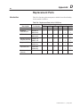
Replacement Parts
Appendix D
Parameter List . . . . . . . . . . . . . . . . . . . . . . . . . . . . . . . . . . . . . . .
Parts Table . . . . . . . . . . . . . . . . . . . . . . . . . . . . . . . . . . . . . . . . .
Publication 1302-5.0 — January, 1998
8-1
8-2
8-4
Appendix A
Service Conditions . . . . . . . . . . . . . . . . . . . . . . . . . . . . . . . . . . . .
Dimensions . . . . . . . . . . . . . . . . . . . . . . . . . . . . . . . . . . . . . . . . .
Environmental Conditions . . . . . . . . . . . . . . . . . . . . . . . . . . . . . . .
Drive Inputs . . . . . . . . . . . . . . . . . . . . . . . . . . . . . . . . . . . . . . . . .
Drive Outputs . . . . . . . . . . . . . . . . . . . . . . . . . . . . . . . . . . . . . . .
User Settings Record
7-1
7-1
7-2
7-3
7-4
7-6
7-8
Chapter 9
Introduction . . . . . . . . . . . . . . . . . . . . . . . . . . . . . . . . . . . . . . . . .
Verifying DC Bus Voltage . . . . . . . . . . . . . . . . . . . . . . . . . . . . . . .
Troubleshooting the Drive Using Fault Codes . . . . . . . . . . . . . . . . .
Accessing and Clearing the Error Log . . . . . . . . . . . . . . . . . . . . . .
Power Module Check . . . . . . . . . . . . . . . . . . . . . . . . . . . . . . . . . .
Technical Specifications
6-1
6-1
6-3
B–1
C–1
D–1
Chapter
1–1
1
Introduction
Manual Objectives
The purpose of this manual is to provide you with the necessary
information to install, program, start up and maintain the 1302 AC
Drive. This manual should be read in its entirety before operating,
servicing or initializing the 1302 Drive.
This manual is intended for qualified electrical personnel responsible
for installing, programming, starting up, and maintaining the 1302
drive.
This manual describes how to install and troubleshoot the 1302 AC
drive. Drive installation consists of the following basic tasks:
• Plan your installation using the guidelines presented in chapter 3.
If your installation must be in compliance with Electromagnetic
Compatibility Standards, read Appendix E also.
• Mount the Drive and install external components according to
the guidelines presented in chapter 4.
• Wire the Drive’s input power, output power, and control signal
terminal strip using the instructions in chapter 5.
• Adjust parameter values, if required. The parameters are
described in chapter 8. For quick reference, the factory-set
values are listed in Appendix B.
• Perform the power-off and power-on checks described in chapter
6 to complete the installation.
If problems occur during Drive operation, refer to chapter 9.
Appendix F lists the parts of the Drive that can be replaced. Before
you begin the installation procedure, become familiar with the Drive
by reading chapter 2, which provides an overview of the Drive and
its features, chapter 7, which describes the operation of the keypad
and the display, and Appendix A, which lists the Drive’s technical
specifications.
Publication 1302-5.0 — January, 1998
1–2
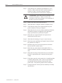
Introduction
!
ATTENTION: Only qualified electrical personnel
familiar with the construction and operation of this
equipment and the hazards involved should install,
adjust, operate and/or service this equipment. Read and
understand this section in its entirety before
proceeding. Failure to observe this precaution could
result in bodily injury or loss of life.
ATTENTION: An incorrectly installed or applied
Drive can result in component damage or a reduction
in product life. Wiring or application errors such as
undersizing the motor, incorrect or inadequate AC
supply or excessive ambient temperatures may result in
damage to the Drive or motor.
ATTENTION: This Drive contains ESD
(Electrostatic Discharge) sensitive parts and
assemblies. Static control precautions are required
when installing, testing, servicing or repairing this
assembly. Component damage may result if ESD
control procedures are not followed. If you are not
familiar with static control procedures, reference
Allen–Bradley Publication 8000 – 4.5.2, Guarding
against Electrostatic Damage or any other applicable
ESD protection handbook.
Publication 1302-5.0 — January, 1998
Chapter
2–1
2
1302 AC Drive Description
Introduction
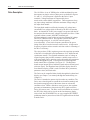
This chapter describes the 1302 Drive and how to identify it based
on its model number. This chapter also provides power and
enclosure rating information.
Standard Features
The 1302 Drive has the following features:
•
•
•
•
•
•
•
On-board keypad and display providing:
Start/Stop/Reset control
Forward/Reverse (reverse-disable selectable)
Setpoint adjustment, Motor RPM, %load, or output voltage
display
Drive diagnostics
500 millisecond power dip ride-through
150% overload for one minute
0.5 to 240 Hz three-phase voltage output
NEMA 1 and NEMA 4/12 enclosures
A snubber resistor braking signal and a scaled voltage analog
output (0 to 10 VDC) which is proportional to:
Output frequency
Output amps
Output voltage
Selected reference
Quiet motor operation with high carrier frequency selection
•
Drive protection:
Overcurrent
Short circuit
Ground fault
Overvoltage
Undervoltage
Overtemperature
•
UL/CSA electronic overload that meets NEC/CEC requirements
•
User-selectable relay contact for indications of Drive running,
Drive faulted, or Drive at selected speed
•
User-selectable power-up start, auto-restart, and coast-to-rest or
ramp-to-rest stop functions
•
User-selectable local or remote operation
•
29 user–adjustable software parameters
Publication 1302-5.0 — January, 1998
2–2
1302 AC Drive Description
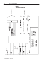
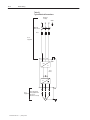
Drive Description
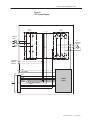
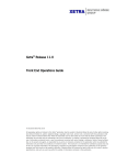
The 1302 Drive is an AC PWM (pulse–width–modulated) inverter
that operates on single–or three–phase power as detailed in Figures
2.1 and 2.2. AC input power is applied to the Drive’s input
terminals. Voltage transients are suppressed by three
metal-oxide-varistor (MOV) suppressors. These suppressors keep
any input voltage transients within the maximum voltage rating of
the input diode module.
The input diode module rectifies the incoming AC voltage into a
constant DC bus voltage which is filtered by the DC bus capacitor
bank. An internal DC-to-DC power supply uses power from the DC
bus and provides the necessary voltages required by the Drive. Under
regulator software control, the IGBT (insulated-gate
bipolar-transistor) inverter bridge converts the constant DC voltage
into an AC PWM waveform. The regulator switches the IGBT
inverter bridge using a 4, 6, or 8 kHz carrier frequency
(user-selectable). A low carrier frequency maximizes the power
rating of the Drive but also increases acoustic noise. A high carrier
frequency selection reduces acoustic noise but results in a derating of
the Drive’s efficiency.
The volts per hertz (V/Hz) regulator governs the open-loop operation
of the Drive for adjustable speed performance of AC induction and
synchronous motors. The regulator maintains a ratio of voltage to
output frequency that provides constant or variable torque across a
wide speed range. Drive operation can be adjusted by the parameters
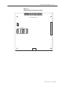
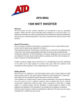
entered through the keypad. A microprocessor on the Regulator
board controls Drive regulation. See Figure 2.3. The Regulator
board accepts internal power feedback signals and an external speed
reference signal. The Regulator board provides display data for a
four-character display, which is used to indicate Drive parameters,
parameter values, and fault codes.
The Drive can be controlled either locally through the keyboard and
display (see Chapter 7) or remotely through the terminal strip (see
Chapter 5).
The Drive is intended to operate trip-free under any condition. The
Drive uses selected signals to extend the acceleration (starting) and
deceleration (stopping) rates of the motor when an overcurrent
condition occurs. When a fault does occur, however, the regulator
generates an instantaneous electronic trip (IET) signal to turn the
Drive off (coast-to-rest). The Drive stores an indication or record of
the IET fault, which can be viewed on the four-character display.
After a fault, the STOP/RESET key or a user-supplied IET RESET
pushbutton must be pressed to reset the IET signal and clear the fault
from the Drive.
Publication 1302-5.0 — January, 1998
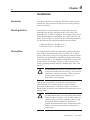
1302 AC Drive Description 2–3
Figure 2.1
1302 System Diagram
DIODE
MODULE
IGBT
MODULE
DC
CT
LINE INPUT
575VAC
R
AC
Induction
U Motor
S
T
+
V
W
TO OPTIONAL
SNUBBER
RESISTOR
+
–
10 VDC
+
–
10 VDC COMMON
24 VDC
24 VDC COMMON
+15 VDC
–15 VDC
TO
FIG
2.2
J4
BUS VOLT
FEEDBACK
POWER
SUPPLY
BUS CURRENT FEEDBACK
+5 VDC
REGULATOR COMMON
GATE SIGNALS
Publication 1302-5.0 — January, 1998
Publication 1302-5.0 — January, 1998
2–4
1302 AC Drive Description
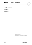
Figure 2.2
1302 System Diagram Cont.
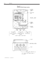
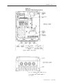
1302 AC Drive Description 2–5
Figure 2.3
Regulator Board Component Locations
%%%%%%
%%%$$$$$$
! " &
!#
&
Publication 1302-5.0 — January, 1998
2–6
1302 AC Drive Description
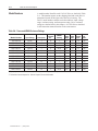
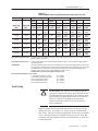
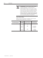
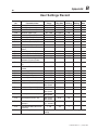
Model Numbers
A model number identifies each 1302 AC Drive as detailed in Table
2.A. This number appears on the shipping label and on the Drive’s
nameplate located on the right side of the Drive housing. The
Drive’s model number contains codes that indicate: input voltage
range, enclosure rating, and horsepower rating. Drive enclosure
ratings are detailed later in this chapter. All 1302 Drives described
in this instruction manual function in the same manner.
Table 2.A - Power and NEMA Enclosure Ratings
Input
Amps
Input
KVA
Power
Output Loss
Amps* Watts**
Input Voltage
Horsepower
Enclosure
Size
1302–C001–AA
575 VAC
1
B
1
2.0
2.0
1.6
50
1302–C001–AF
575 VAC
1
B
4X/12
2.0
2.0
1.6
50
1302–C002–AA
575 VAC
2
B
1
3.4
3.3
2.7
90
1302–C002–AF
575 VAC
2
B
4X/12
3.4
3.3
2.7
90
1302–C003–AA
575 VAC
3
B
1
5.2
5.1
4.3
120
1302–C003–AF
575 VAC
3
B
4X/12
5.2
5.1
4.3
120
1302–C005–AA
575 VAC
5
B
1
7.5
7.5
6.2
150
1302–C005–AF
575 VAC
5
B
4X/12
7.5
7.5
6.2
150
1302–C007–AA
575 VAC
7.5
C
1
10.9
10.9
9.0
180
1302–C007–AF
575 VAC
7.5
C
4X/12
10.9
10.9
9.0
180
1302–C010–AA
575 VAC
10
C
1
14.5
14.4
12.0
250
1302–C010–AF
575 VAC
10
C
4X/12
14.5
14.4
12.0
250
* To properly size the drive for motor nameplate horsepower and amps, refer to Chapter 3 for more information.
** Full load at all carrier frequencies. Refer to Chapter 3 for more information.
Publication 1302-5.0 — January, 1998
1302 AC Drive Description 2–7
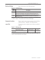
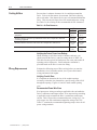
Enclosure Ratings
Each 1302 Drive has one of the following ratings:
Table 2.B - 1302 NEMA Ratings
NEMA
Rating
1
4X/12
12
Description
Vented. For generalĆpurpose indoor applications.
Not vented. Supplied with base and keypad gaskets. For use in indoor
environments that require a waterĆtight and dustĆtight enclosure. An
enclosure with this NEMA rating encompasses both ratings (4X and 12).
Intended for use in indoor environments that require a dustĆtight and
dripĆtight enclosure.
For clarity in this manual, 1302 Drive enclosures are identified by size as enclosures B or
C. Refer to Chapter 3 for the dimensions of enclosures B through C.
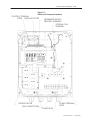
Component Locations
Figures 2.4 and 2.5 show the main components of the 1302 Drives
(enclosures B and C). Appendix F lists replacement parts.
Option Kits
The option kit which is available for the 1302 Drive is detailed in
Table 2.C.
Table 2.C - 1302 Option Kits
Option Kit Description
Low Energy Snubber Resistor Braking Kit for
1302 Drives*
Option Kit
Model Number
Instruction
Manual
1302-2DB5010
1302-5.1
** Snubber resistor braking kits require connection to the snubber resistor braking 10V power supply. See
Chapter 5 (Snubber resistor wiring) for more information.
Publication 1302-5.0 — January, 1998
2–8
1302 AC Drive Description
Figure 2.4
Enclosure B Component Locations
CONTROL TERMINAL
STRIP
REGULATOR PCB
MEMBRANE SWITCH/
BRACKET ASSEMBLY
INTERNAL FAN
ASSEMBLY
CAPACITOR PCB
(3&5 HP ONLY)
POWER PCB
GND CONNECTION
POWER TERMINAL
STRIP
Publication 1302-5.0 — January, 1998
1302 AC Drive Description 2–9
Figure 2.5
Enclosure C Component Locations
CONTROL TERMINAL
STRIP REGULATOR PCB
MEMBRANE SWITCH/
BRACKET ASSEMBLY
INTERNAL FAN
ASSEMBLY
POWER TERMINAL
STRIP
CAPACITOR PCB
GND CONNECTIONS
POWER PCB
Publication 1302-5.0 — January, 1998
2–10
1302 AC Drive Description
This Page Intentionally Blank
Publication 1302-5.0 — January, 1998
1302 AC Drive Description 2–11
Publication 1302-5.0 — January, 1998
2–12
1302 AC Drive Description
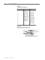
Table 2.A
1302 Model Number Notation
Model Number
1.5
2
3
5
7.5
10
15
20
25
30
40
50
60
75
100
125
150
Input Voltage
6.2 Nm (55 lb-in)
6.2 Nm (55 lb-in)
6.2 Nm (55 lb-in)
6.2 Nm (55 lb-in)
6.2 Nm (55 lb-in)
6.2 Nm (55 lb-in)
13.6 Nm (120 lb-in)
13.6 Nm (120 lb-in)
13.6 Nm (120 lb-in)
13.6 Nm (120 lb-in)
22 Nm (200 lb-in)
22 Nm (200 lb-in)
22 Nm (200 lb-in)
22 Nm (200 lb-in)
—
—
Horsepower
—
—
6.2 Nm (55 lb-in)
6.2 Nm (55 lb-in)
6.2 Nm (55 lb-in)
6.2 Nm (55 lb-in)
6.2 Nm (55 lb-in)
6.2 Nm (55 lb-in)
6.2 Nm (55 lb-in)
13.6 Nm (120 lb-in)
13.6 Nm (120 lb-in)
13.6 Nm (120 lb-in)
13.6 Nm (120 lb-in)
22 Nm (200 lb-in)
22 Nm (200 lb-in)
22 Nm (200 lb-in)
22 Nm (200 lb-in)
Note:
Figure 2.19
Motor Thermostat/Brush Wear Wiring
12
13
14
BRUSH WEAR
MOTOR THERMOSTAT
115V HI
115VAC Option Board CON 2
115VAC Thermostat/Brush Wear Circuit
Publication 1302-5.0 — January, 1998
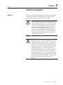
Chapter
3–1
3
1302 Preinstallation
General
Chapter 3 provides information that you must use when planning a
1302 AC Drive installation. Installation site, wiring and motor
application requirements are included in this chapter.
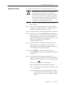
!
!
ATTENTION: The following information is merely a
guide for proper installation. The National Electrical
Code and any other governing regional or local code
will overrule this information. The Allen–Bradley
Company cannot assume responsibility for the
compliance or noncompliance to any code, national,
local or otherwise for the proper installation of this
Drive or associated equipment. A hazard of personal
injury and/or equipment damage exists if codes are
ignored during installation.
ATTENTION: Hazard of electric shock or equipment
damage exist if the Drive is not installed correctly. The
National Electrical Code (NEC) and local codes outline
provisions for safely installing electrical equipment.
Installation must comply with specifications regarding
wire types, conductor sizes, branch circuit protection
and disconnect devices. Only qualified electrical
personnel familiar with the construction and operation
of the 1302 Drive and the hazards involved should
install, adjust, operate, or service this equipment. Read
and understand this manual and other applicable manuals in their entirety before proceeding. Failure to do so
may result in personal injury and/or equipment
damage.
Publication 1302-5.0 — January, 1998
3–2
1302 Preinstallation
Site Requirements
It is important to properly plan before installing a 1302 Drive to
ensure that the Drive’s environment and operating conditions are
satisfactory. Note that no devices are to be mounted behind the
Drive. This area must be kept clear of all control and power wiring.
Read the following recommendations before continuing with the
Drive installation.
Before deciding on an installation site, consider the following
guidelines:
• The area chosen should allow the space required for proper airflow
as specified in the next section.
• Do not install the Drive above 1000 meters (3300 feet) without
derating output power. For every 91.4 meters (300 feet) above
1000 meters (3300 feet), derate the output current by 1%.
• Verify that the Drive location will meet the following
environmental conditions:
Operating temperature (ambient): 0 to +40°C (32 to 104°F)
Storage temperature (ambient): – 40 to +65°C (–40 to +149°F)
Humidity: 5 to 95% (non-condensing)
• Verify that NEMA 1 Drives can be kept clean, cool, and dry.
• Be sure NEMA 1 Drives are located away from oil, coolants, or
other airborne contaminants.
• Verify that the AC power distribution system meets the service
conditions specified in table
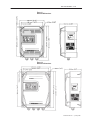
Determining Total Area Requirements
Figures 3.1 and 3.2 provide drive dimensions for enclosures B and C
as an aid in calculating the total area required by the 1302 Drives.
Appendix A lists drive weights.
Publication 1302-5.0 — January, 1998
1302 Preinstallation 3–3
Figure 3.1
Enclosure B Dimensions
Figure 3.2
Enclosure C Dimensions
Publication 1302-5.0 — January, 1998
3–4
1302 Preinstallation
Cooling Airflow
Be sure there is adequate clearance for air ventilation around the
Drive. For best air movement, do not mount 1302 Drives directly
above each other. Note that no devices are to be mounted behind the
Drive. This area must be kept clear of all control and power wiring.
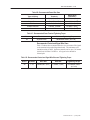
See Table 3.A for a listing of the recommended air flow clearances.
Table 3.A - Air Flow Clearance
Minimum distance from the sides of the drive if adjacent to non-heat producing
equipment
102 mm
(4”)
102 mm
(4”)
Minimum distance from the top and bottom of the drive if adjacent to non-heat
producing equipment
102 mm
(4”)
102 mm
(4”)
Minimum distance from the sides of the drive if adjacent to other drives
102 mm
(4”)
102 mm
(4”)
Minimum distance from the top and bottom of the drive if adjacent to other drives
254 mm
(10”)
254 mm
(10”)
Verifying the Drive’s Power Loss Ratings
When installing a 1302 Drive inside of another enclosure, you
should consider the Drive’s watts loss rating shown in Table 2.A.
This table lists the typical full load power loss watts value under all
operating carrier frequencies. Ensure adequate ventilation is
provided based on the Drive’s watts loss rating.
Wiring Requirements
Evaluate the following areas of Drive wiring before you start the
installation: size of available conduit, size of power and control
wiring, and motor lead lengths.
Verifying Conduit Sizes
It is important to determine the size of the conduit openings
accurately so that the wire planned for a specific entry point will fit
through the opening. Figures 4.1 and 4.2 detail conduit opening
sizes.
Recommended Power Wire Sizes
Size input power wiring according to applicable codes to handle the
Drive’s continuous-rated input current. Size output wiring according
to applicable codes to handle the Drive’s continuous-rated output
current. Table 3.B provides recommended power wiring sizes. Use
only copper wire with a minimum temperature rating of 60/75°C.
Table 3.C contains the recommended tightening torque values for all
power wiring terminals.
Publication 1302-5.0 — January, 1998
1302 Preinstallation 3–5
Table 3.B - Recommended Power Wire Sizes
Type of Wiring
Terminals
Size of Wire
(maximum)*
AC Input Power
R(L1), S(L2), T(L3)
14 AWG, 2 (mm2)
Output Power
U(T1), V(T2), W(T3)
14 AWG, 2 (mm2)
DC Bus
ć,+
14 AWG, 2 (mm2)
Snubber Resistor
+10 VDC, 10 COM
14 AWG, 2 (mm2)
Ground
GND
14 AWG, 2 (mm2)
Table 3.C - Recommended Power Terminal Tightening Torque
Drives
Terminals
Maximum Tightening Torque
All
All power wires
1.08 NewtonĆmeters (9.5 inĆlb)
Recommended Control and Signal Wire Sizes
Table 3.D shows the recommended wire sizes to connect I/O signals
to the terminal strip on the Regulator board. The minimum wire
insulation rating is 600V. Operator controls can be up to 303 meters
(1000 feet) from the 1302 Drive. All signal wires should be
twisted-pair.
Table 3.D - Recommended Control and Signal Wire Sizes and Tightening Torque
Drives
Terminals
Minimum
Wire Size
Maximum
Wire Size
Maximum
Tightening Torque
All
1ć16
20 AWG, 0.5 (mm2)
14 AWG, 2 (mm2)
0.5 NewtonĆmeters
(4.5 inĆlb)
Publication 1302-5.0 — January, 1998
3–6
1302 Preinstallation
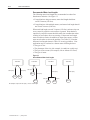
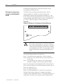
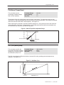
Recommended Motor Lead Lengths
The following motor lead lengths are recommended to reduce line
disturbances and noise. See Figure 3.3.
• For applications using one motor, motor lead length should not
exceed 76 meters (250 feet).
• For applications with multiple motors, total motor lead length should
not exceed 76 meters (250 feet).
When total lead length exceeds 76 meters (250 feet), nuisance trips can
occur, caused by capacitive current flow to ground. Note that these
capacitively-coupled currents should be taken into consideration when
working in areas where drives are running. If the motor lead length
must exceed these limits, the addition of output line reactors or other
steps must be taken to correct the problem. See Table 3.E. Note that
the motor lead lengths shown in Table 3.E are only guidelines. Your
application may be restricted to a shorter motor lead length due to:
•
•
•
•
The type of wire
The placement of the wire (for example, in conduit or a cable tray)
The type of line reactor (For example, with or without LC filters)
The type of motor
Figure 3.3
How to Measure Motor Lead Lengths
! Publication 1302-5.0 — January, 1998
1302 Preinstallation 3–7
Table 3.E
Maximum Motor Cable Length Restrictions in meters (Feet) for 1302
No External Devices
Motor
A
w/ Reactor/Filter at Drive
Motor
Motor
1329R
A
B
1329R
A
B
1329R
Any
Cable
Any
Cable
Any
Cable
Any
Cable
Any
Cable
Any
Cable
Any
Cable
NR
121.9
(400)
152.4
(500)
NR
NR
NR
121.9
(400)
152.4
(500)
2.2 (3)
NR
NR
NR
152.4
(500)
304.8
(1000)
152.4
(500)
3.7 (5)
3.7 (5)
NR
NR
304.8
(1000)
5.6 (7.5)
5.6 (7.5)
NR
NR
NR
NR
NR
7.5 (10)
7.5 (10)
NR
NR
NR
NR
NR
Drive kW
(HP)
Motor kW
(HP)
0.75 (1)
0.75 (1)
NR
1.5 (2)
1.5 (2)
2.2 (3)
B
w/ 1204–TFA1 Terminator
Any
Any
Cable Cable
Type A Motor Characteristics:
No phase paper or misplaced phase paper, lower quality insulation systems, corona inception voltages
between 850 and 1000 volts
Type B Motor Characteristics:
Properly placed phase paper, medium quality insulation systems, corona inception voltages between
1000 and 1200 volts.
1329R Motors
These AC Variable Speed motors are “Power Matched” for use with Allen–Bradley Drives. Each motor
is energy efficient and designed to meet or exceed the requirements of the Federal Energy Act of 1992.
All 1329R motors are optimized for variable speed operation and include premium inverter grade
insulation systems which meet or exceed NEMA MG1. Part 31.40.4.2
1329R motors at 575V are rated 1850V insulation value.
Recommended MTE Reactor and LC Filter:
1 hp at 4kHz use MTE part number:
1 hp at 6/8kHz use MTE part number
2/3/5 hp use MTE part number
7.5 hp use MTE part number
10 hp use MTE part number
RL– 00803C
RL– 00202C
RL– 00803C
RL– 01803C
RL– 01803C
Input Fusing
!
ATTENTION: The 1302 AC Drive does not provide
input power short circuit fusing. Specifications for the
recommended fuse size and type to provide Drive input
power protection against short circuits are provided in
Table 3.F. Branch circuit breakers or disconnect
switches cannot provide this level of protection for
Drive components.
Input line branch circuit protection fuses must be used to protect the
input power lines. See Figure 5.A. Table 3.F shows recommended
fuse values. These fuse ratings are applicable for one Drive per branch
circuit. No other load may be applied to that fused circuit. Note that
contactors and circuit breakers are not recommended for AC input line
branch protection.
Publication 1302-5.0 — January, 1998
3–8
1302 Preinstallation
Table 3.F- AC Input Line Fuse Selection Values
Model
Number
Fuse
Rating*
1302–C001–AA
4A
1302–C001–AF
4A
1302–C002–AA
7A
1302–C002–AF
7A
1302–C003–AA
10A
1302–C003–AF
10A
1302–C004–AA
15A
1302–C005–AA
15A
1302–C005–AF
20A
1302–C007–AF
20A
1302–C010–AA
25A
1302–C010–AF
25A
Emergency Stop Installation
!
ATTENTION: The 1302 Drive control circuitry
includes solid state components. If hazards due to
accidental contact with moving machinery or
unintentional flow of liquid, gas or solids exist, an
additional hardwired stop circuit is required to remove
AC line power to the Drive. When AC input power is
removed, there will be a loss of inherent regenerative
braking effect and the motor will coast to a stop. An
auxiliary braking method may be required.
Depending upon the requirements of the application, the 1302 Drive
can be programmed to provide either a coast-to-rest (default) or a
ramp-to-rest (user-option) operational stop without physical separation
of the power source from the motor. Refer to Chapters 5 and 8
(parameter F-16) for more information on how to program an
operational stop.
In addition to the operational stop, users must provide a hardwired
emergency stop external to the Drive. The emergency stop circuit must
contain only hardwired electromechanical components. Operation of
the emergency stop must not depend on electronic logic (hardware or
software) or on the communication of commands over an electronic
network or link.
Complying with Machinery Safety Standard EN 6024–1:1992
This section applies to users who must comply with machinery safety
standard EN 60204-1:1992, part 9.2.5.4, Emergency Stop.
The 1302 Drive coast-to-rest stop is a category 0 operational stop. The
ramp-to-rest stop is a category 1 operational stop.
Publication 1302-5.0 — January, 1998
1302 Preinstallation 3–9
The required external hardwired emergency stop must be either a
category 0 or 1 stop, depending on the user’s risk assessment of the
associated machinery. In order to fully comply with machinery
safety standard EN 60204-1:1992, part 9.2.5.4, at least one of the
two stop methods must be a category 0 stop.
Motor Considerations
To obtain motor nameplate horsepower, the Drive’s output current
rating at the selected carrier frequency should be equal to or greater
than motor nameplate current. If the motor nameplate current rating
is higher than the Drive’s output current rating, derate motor
horsepower by the ratio of the Drive’s output ampere rating (at the
selected carrier frequency) to the motor nameplate current. Note that
this approximation is only accurate if the Drive and the motor have
nearly the same rating.
Single Motor Applications
Size the drive and motor for the load and speed requirements of the
specific application.
The motor’s operating current must not exceed the drive’s rated
output current (at the selected carrier frequency). In addition, the
motor’s horsepower rating (for example, 1, 2, 3, 5, 7, 10 HP) must
not be more than one horsepower range larger than the Drive’s
horsepower rating.
If the motor will be operated below one-half of its rated speed, the
motor overload relay may not protect the motor because of reduced
cooling action due to the reduced speed. A motor thermostat,
internal to the motor, should be installed to monitor the actual
temperature of the windings.
Multiple – Motor Applications
One Drive can run two or more motors. Adhere to the following
requirements to assure correct Drive operation in this case:
• When starting and stopping all the motors at the same time (using
the Drive for starting and stopping), the sum of the full-load sine
wave currents of all the motors must be equal to or less than the
maximum sine wave output current at the selected carrier
frequency for the Drive.
! &
#! #! #! # !
!# !% $#$# # # "# !!! ! $'
• When one or more of the motors connected to the output of the
Drive are to start independently (using a secondary switching
device to add or remove the motor from the circuit):
Any motor that starts or stops while the Drive is running must
have a current rating less than 10% of the maximum sine wave
current rating of the Drive at the selected carrier frequency.
Publication 1302-5.0 — January, 1998
3–10
1302 Preinstallation
The sum of the maximum full-load sine wave currents of all the
motors connected continuously to the Drive must be less than the
maximum output current rating under all conditions.
Note that each motor requires separate thermal overload protection
(for example, a motor relay or a motor thermostat).
Publication 1302-5.0 — January, 1998
Chapter
4–1
4
Installation
Introduction
This chapter shows how to mount the 1302 Drive and its external
components. Also shown are the entry areas for routing wiring in
and out of the Drive.
Mounting the Drive
Attach the drive to the selected flat, vertical surface using the
mounting holes provided. Enclosure B and C Drives have four
mounting holes. In order to maintain a flat mounting surface and to
ensure that bolt tightness is maintained, use washers under the bolt
heads. Refer to Figures 3.1 and 3.2 for Drive mounting dimensions.
Use the following user-supplied mounting bolts and washers:
• Enclosure B Drives: four M8 (5/16”)
• Enclosure C Drives: four M8 (5/16”)
Routing Wires
All wiring should be installed in conformance with the applicable
local, national, and international codes (e.g., NEC/CEC). Signal
wiring, control wiring, and power wiring must be routed in separate
conduits to prevent interference with Drive operation. Do not route
wires behind the Drive. Use grommets when hubs are not provided
to guard against wire chafing. Figures 4.1 and 4.2 show the wire
routing, grounding terminal, and power terminal strips of the 1302
Drives.
!
ATTENTION: Do Not route signal and control wiring
in the same conduit with power wiring. This can cause
interference with Drive operation. Failure to observe
this precaution could result in damage to, or
destruction of, the equipment.
Do not route more than three sets of motor leads through a single
conduit. This will minimize cross-talk that could reduce the
effectiveness of noise reduction methods. If more than three
Drive/motor connections per conduit are required, you must use
shielded cable. If possible, each conduit should contain only one set
of motor leads.
!
ATTENTION: Unused wires in conduit must be
grounded at both ends to avoid a possible shock hazard
caused by induced voltages. Also, if a Drive sharing a
conduit is being serviced or installed, all Drives using
this conduit should be disabled to eliminate the
possible shock hazard from cross–coupled motor leads.
Failure to observe these precautions could result in
bodily injury.
Publication 1302-5.0 — January, 1998
4–2
Installation
Figure 4.1
Enclosure B Wire Routing Locations
Publication 1302-5.0 — January, 1998
Installation 4–3
Figure 4.2
Enclosure C Wire Routing Locations
Publication 1302-5.0 — January, 1998
4–4
Installation
External Component
Installation
Install the input power and output power components that are located
outside of the 1302 enclosure. See Figure 5.1. The following
sections describe disconnect, transformer, and AC line branch
protection installation
Disconnects
An input disconnect (for example, a switch or circuit breaker) must
be installed in the line before the Drive input terminals in accordance
with local, national, and international codes (e.g., NEC/CEC). Size
the disconnect according to the inrush current as well as any
additional loads the disconnect might supply. Coordinate the trip
rating for the current (10 to 12 times the full load current) with that
of the input isolation transformer, if used. Refer to the Transformers
section of this chapter for additional information.
Input AC Line Branch Protection
!
ATTENTION: Most codes require that upstream
branch protection be provided to protect input power
wiring. To guard against personal injury and/or
equipment damage caused by improper fusing, use
only properly rated line fuses. Branch circuit breakers
or disconnect switches cannot provide this level of
protection for Drive components.
User-supplied branch circuit protection fuses must be installed
according to the applicable local, national, and international codes
(for example, NEC/CEC). The fuses must be installed in the line
before the Drive’s AC input terminals. Table 3.F provides fuse
values.
Transformers
!
ATTENTION: If the AC input power system does not
have a neutral or one phase referenced to ground, an
isolation transformer with the neutral of the secondary
grounded is highly recommended. If the line–to–line
voltages on any phase can exceed 125% of the nominal
line–to–line voltage, an isolation transformer with the
neutral of the secondary grounded, is always required.
Failure to observe these precautions could result in
bodily injury or damage to equipment.
ATTENTION: When the AC line is shared directly
with other SCR–rectified drives, an optional snubber
resistor braking kit might be required to alleviate
excess DC bus voltage. Failure to observe these
precautions could result in damage to, or destruction
of, the equipment.
Publication 1302-5.0 — January, 1998
Installation 4–5
Input isolation transformers may be needed to help eliminate the
following:
•
•
•
Damaging line voltage transients.
Line noise from the Drive back to the incoming power source.
Damaging currents that could develop if a point inside the Drive
becomes grounded.
Observe the following guidelines when installing an isolation
transformer:
•
•
A power disconnecting device must be installed between the
power line and the primary of the transformer. If the power
disconnecting device is a circuit breaker, the circuit breaker trip
rating must be coordinated with the inrush current (10 to 12
times the full load current) of the transformer.
Do NOT use an input isolation transformer rated more than 100
KVA for 230 VAC (or 1000 KVA for 460 VAC) with less than
5% impedance directly ahead of the Drive without additional
impedance between the Drive and the transformer.
If your 1302 application requires the use of an output transformer,
contact Allen–Bradley for assistance.
Output Contactors
!
ATTENTION: Any disconnecting means wired to
drive output terminals U,V, and W must be capable of
disabling the Drive if opened during Drive operation.
If opened during Drive operation, the Drive will
continue to produce output voltage between U, V, and
W. An auxiliary contact must be used to
simultaneously disable the Drive or output component
damage may occur.
Output contactors provide a positive means of disconnecting the
motor from the Drive. If your 1302 application requires the use of
output contactors, contact Allen–Bradley for assistance.
Mechanical Motor Overload Protection
To provide the motor with overload protection, local, national, and
international codes (for example, NEC/CEC) require that a motor
thermostat, internal to the motor, be installed or an electronic thermal
motor overload relay, sized to protect the motor, be installed between
the motor and the Drive’s output terminals.
The Electronic Thermal Overload parameter (F-14) may be used in
place of the electronic thermal motor overload relays in single motor
applications. Note, however, that temperature-sensing devices
integral to the motor are the best way of thermally-protecting AC
motors under all conditions. Parameter F-14 must be enabled to
provide overload protection. Refer to Chapter 8 for the parameter
description.
Publication 1302-5.0 — January, 1998
4–6
Installation
In multiple motor applications, each motor must have its own
user-supplied overload protection.
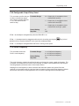
Setting the Analog Input
Jumper on the Regulator
Board
1302 Drives have an analog speed reference input. This is a
jumper-selectable 0 to 10 VDC or 0 to 20 mA input with
programmable gain and offset adjustments (parameters F-11 and
F-12). Jumper J6 on the Regulator board is set to match the type of
incoming analog signal, either voltage or current. See Figures 2.2,
4.3, and 5.3. Refer to Chapter 5 for more information.
Figure 4.3
Jumper J6 Settings for the Analog Input Speed Reference
!
ATTENTION: Disconnect and lock out power to the
Drive before setting Jumper J6. Failure to disconnect
power may result in death or serious injury. Verify bus
voltage using the following procedure before touching
any components in the drive. Do not attempt to service
the Drive until the bus voltage has discharged to zero
volts.
Use the following procedure to set jumper J6:
Step 1. Turn off and lock out input power. Wait five minutes
Step 2. Remove the cover from the Drive by unscrewing the four
cover screws.
Step 3. Verify that the DC bus voltage is zero by following the
procedure in Chapter 9 titled Verifying DC Bus Voltage.
Step 4. Locate jumper J6 on the Regulator board. Refer to Fig. 2.3
Step 5. Move the jumper to the desired setting as detailed in Fig. 4.3
Step 6. Re–attach the cover
Step 7. Re–apply input power
Step 8. Verify that parameters F–11 and F–12 are correctly set.
Note that if the setting of jumper J6 is changed, the regulator
software will not automatically detect it. Verify that parameters F-11
(gain) and F-12 (offset) are set correctly before starting the Drive.
Publication 1302-5.0 — January, 1998
Installation 4–7
Motor Preparation
Follow these guidelines when preparing to install the motor:
• Verify that the motor is the appropriate size to use with the
Drive.
• Verify that the total motor lead length does not exceed the
values given in Chapter 3.
• Follow the instructions in the motor instruction manual when
installing the motor.
• Verify that the motor is properly aligned with the application’s
machine to minimize unnecessary motor loading due to shaft
misalignment.
• If the motor is accessible when it is running, install a protective
guard around all exposed rotating parts.
Publication 1302-5.0 — January, 1998
4–8
Installation
This Page Intentionally Blank
Publication 1302-5.0 — January, 1998
Chapter
5–1
5
Drive Wiring
Introduction
This chapter describes how to wire the 1302 Drive including: input
wiring, control and signal wiring, output wiring, and grounding.
Input Power Wiring
Use the following steps to connect AC input power to the Drive:
Step 1. Verify that the AC input power to the Drive corresponds to
the drive’s nameplate voltage and frequency.
Step 2. Wire the AC input power leads by routing them according to
the type of enclosure. Sees Figures 4.1 and 4.2 and Table
3.B for recommended wire sizes.
!
ATTENTION: Do Not route signal and control wiring
with power wiring in the same conduit. This can cause
interference with Drive operation. Failure to observe
this precaution could result in erractic drive operation
or damage to, or destruction of, the equipment.
Step 3. Connect the AC input power leads to terminals R,S,T on the
power terminal strip.
Step 4. Tighten terminals R and S (single–phase input) or terminals
R,S,T (three–phase input) to the proper torque as shown in
Table 3.D.
Publication 1302-5.0 — January, 1998
5–2
Drive Wiring
Table 5.1
Typical Electrical Connections
AC Input
Voltage
GND
Manual
Disconnect
Fuse
UserĆ
Supplied
R/L1 S/L2 T/L3
~ -
GND
1302
Drive
U/T1
Motor Overload
UserĆ
Relay (Optional if
Supplied Electronic
Overload is Used)
ũ
Ũ
~
V/T2 W/T3
ũ
Ũ
M
Publication 1302-5.0 — January, 1998
ũ
Ũ
GND
Drive Wiring 5–3
The Terminal strip on the Regulator board provides terminals for
connecting signal (for example, external speed reference and analog
output) and control (for example, stop, start, and function loss)
wiring. See Figure 5.2. Terminals for the following wire
connections are provided:
•
•
•
•
•
Terminals 1–3: analog speed reference connections
Terminals 4–5: analog output connections
Terminals 6–11: digital input connections
Terminals 12–13: snubber resistor connections
Terminals 14–16: output status connections
Analog
Speed
Reference
Analog
Output
Digital
Inputs
Snubber
Resistor
Braking
Signal
N.C. Relay Contact
N.O. Relay Contact
Relay Common
24 VDC Common
Snubber Resistor Braking Signal
24 VDC Common
Function Loss
Forward/Reverse
Reset
Start
Stop
24 VDC Common
Analog Meter Output
Isolated Reference Ground
Voltage/Current Speed Reference
Table 5.2
Typical Control Terminal Strip Connections
Isolated Reference Voltage
Signal and Control Wiring
Output
Status
Relay
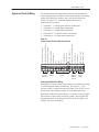
Analog Speed Reference Wiring
Analog speed reference input wiring connects to terminals 1 through
3 on the Regulator board’s teminal strip. See Figure 5.3. This
reference signal is jumper-selectable for either a 0 to 10 VDC or 0 to
20 mA input. The setting of jumper J6 on the Regulator board
determines whether the input reference is a voltage or current signal.
This reference signal can be provided by either a user-supplied 5K
ohm potentiometer or an external 0-10 VDC/0-20 mA supply. See
Chapter 4 for more information.
Publication 1302-5.0 — January, 1998
5–4
Drive Wiring
Table 5.3
Analog Speed Reference Wiring Connections
"!%$ !
$# "!%$ !
###!
%
!
%
Ω
!
Analog Output Wiring
Analog output wiring connects to terminals 4 and 5 on the Regulator
board’s terminal strip. See Figure 5.4. This is a scaled 0 to 10 VDC
output signal that is proportional to either current speed, percent of
load, calculated output voltage, or percent of the selected reference
value, whichever is selected through parameter F-29. This output
signal is available during both local and remote operation.
Figure 5.4
Analog Output Wiring Connections
"!%$ #!
Digital Input Wiring
Publication 1302-5.0 — January, 1998
Digital input wiring connects to terminals 6 through 11 on the
Regulator board’s terminal strip. The Drive has a 24 VDC power
supply that provides the required voltage for control signals.
Enabling or disabling a control signal requires that a contact (switch)
be opened or closed.
Drive Wiring 5–5
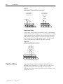
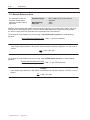
Start and Stop Control Wiring
Start and stop control wiring connects to terminals 6, 7, and 11. See
Figures 5.5 and 5.6. Note that these start/stop wiring connections are
not to be used in multi-speed preset applications which are discussed
in the following section.
Figure 5.5
Two–Wire Start/Stop Sample Control Wiring
Figure 5.6
Three–Wire Start/Stop Sample Control Wiring
Publication 1302-5.0 — January, 1998
5–6
Drive Wiring
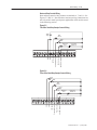
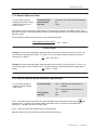
Multi–Speed Preset Wiring
Multi-speed preset wiring connects to terminals 6 through 8, and 11.
See Figure 5.7. When control type 3 is selected through parameter
F-00, remote terminal strip control is enabled with multi-speed
presets. This mode of operation changes the functionality of
terminals 6 through 8 and may be used in place of 2- and 3-wire
start/stop wiring. See Figure 5.8.
When you enable multi-speed preset operation, the state of terminals
7 and 8 determine the source of the speed reference:
0
0
Terminal Strip Analog Input
0
1
MultiĆSpeed Preset 1 (Parameter FĆ23)
1
0
MultiĆSpeed Preset 2 (Parameter FĆ24)
1
1
MultiĆSpeed Preset 3 (Parameter FĆ25)
Figure 5.7
Multi–Speed Preset Sample Control Wiring
Start/Stop/IET Reset
MultiĆSpeed Preset 1
MultiĆSpeed Preset 2
Fwd
Rev
Publication 1302-5.0 — January, 1998
24 VDC Common
Function Loss
Forward/Reverse
MultiĆSpeed Preset 2
MultiĆSpeed Preset 1
Start/Stop/IET Reset
Function
Loss
Customer
Interlock
Drive Wiring 5–7
Figure 5.8
Terminal Usage During Multi–Speed Preset Operation
FĆ00 = 0, 1, 2
%"##$ "
"
%$ ##
"'"&"#
#$
$"$
$ !
$"%$!%$
FĆ00 = 3 (MultiĆSpeed Presets)
%"##$ "
"
%$ ##
"'"&"#
%$(!"#$
%$(!"#$
$"$$ !
#$
$"%$!%$
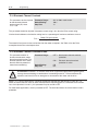
IET Reset Control Wiring
IET reset control wiring connects to terminals 8 and 11. See Figures
5.5 and 5.6. Note that these reset wiring connections are not to be
used in multi-speed preset applications. See Figures 5.7 and 5.8.
Forward/Reverse Control Wiring
Forward/reverse control wiring connects to terminals 9 and 11. See
Figures 5.5 through 5.7. Note that the setting of the forward/reverse
switch is ignored when parameter F-17 is equal to 1 (disable reverse
operation).
Function Loss Control Wiring
Function loss control wiring connects to terminals 10 and 11. See
Figures 5.5 through 5.7. Typically, a function loss input is a
maintained, normally-closed pushbutton.
A signal must be present at terminal 10 for the Drive to run. A
factory-installed jumper connects terminals 10 and 11 which
provides that signal. Remove this jumper if a function loss input, a
coast-stop pushbutton, or another external interlock (for example, a
motor thermostat) is used. Removing the jumper allows the Drive to
stop when the contact is open.
Publication 1302-5.0 — January, 1998
5–8
Drive Wiring
!
ATTENTION: The 1302 control circuitry includes
solid state components. You must provide an
additional hardwired stop circuit to remove AC line
power to the Drive in the case of improper operation.
Failure to provide a hardwired emergency stop could
result in equipment damage, bodily injury or death.
When AC input power is removed, there will be a loss
of inherent regenerative braking effect and the motor
will coast to a stop. An auxiliary braking method may
also be required depending on the application.
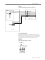
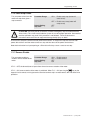
Snubber Resistor Wiring
Snubber resistor wiring connects to terminals 12 and 13 on the
Regulator board’s terminal strip. See Figure 5.9.
Publication 1302-5.0 — January, 1998
Drive Wiring 5–9
Figure 5.9
Snubber Resistor Wiring Connections for 1302 Drives
REGULATOR
BOARD
24 VDC COMMON
12 13
SNUBBER RESISTOR
BRAKING SIGNAL
CONTROL
TERMINAL
STRIP
+1
-2
POWER
TERMINAL
STRIP
SNUBBER RESISTOR
BRAKING SIGNAL
+147
-45
DC BUS VOLTS
+13
-14
10V SUPPLY
SNUBBER RESISTOR
+ - + DC BUS 10V 10V
VOLTS
COM
SP500 DRIVE
Output Status Relay Wiring
Output status wiring connects to terminals 14 through 16 on the
Regulator board’s terminal strip. See Figure 5.10. Parameter F-09
specifies the type of status indication provided by the output relay.
See the F-09 parameter description in Chapter 8 for more
information.
Figure 5.10
Output Status Relay Wiring Connections
USERĆSUPPLIED
LAMP
USERĆSUPPLIED
115 VAC / 24 VDC
(10 mA Min.)
N.O.
14
15 16
Publication 1302-5.0 — January, 1998
5–10
Drive Wiring
Output Power Wiring
Use the following steps to connect AC output power wiring from the
Drive to the motor:
Step 1. Wire the AC output power leads by routing them according
to the type of enclosure. See Figures 4.1 and 4.2. See
Table 3.B for recommended wire sizes.
!
ATTENTION: Do not route signal and control wiring
in the same conduit with power wiring. This can cause
interference with Drive operation. Failure to observe
this precaution could result in damage to, or
destruction of, the equipment.
Do not route more than three sets of motor leads through a
single conduit. This will minimize cross-talk which could
reduce the effectiveness of noise reduction methods. If
more than three Drive/motor connections per conduit are
required, you must use shielded cable. If possible, each
conduit should contain only one set of motor leads.
!
ATTENTION: Unused wires in conduit must be
grounded at both ends to avoid a possilble shock
hazard caused by induced voltages. If a Drive sharing
a conduit is being serviced or installed, all Drives using
this conduit should be disabled to eliminate the
possible shock hazard from cross coupled motor leads.
Failure to observe these precautions could result in
bodily injury.
Step 2. Connect the AC output power motor leads to terminals U, V
and W on the power terminal strip.
Step 3. Tighten terminals U, V, and W to the proper torque as
shown in Table 3.D.
Grounding
Use the following steps to ground the Drive:
!
ATTENTION: You are responsible for conforming
with all applicable local, national and international
codes when grounding the Drive. Failure to observe
precautions and meet code could result in equipment
damage or personal injury.
Step 1. Remove the Drive’s cover.
Step 2. Run a suitable equipment grounding conductor unbroken
from the Drive’s ground terminal to the motor’s ground
terminal and then to earth ground. Refer to Figures 4.1,
4.2 and 5.1.
Step 3. Run a suitable grounding connector to the motor frame and
transformer (if used).
Step 4. Re–attach the Drive’s cover
Publication 1302-5.0 — January, 1998
Chapter
6–1
6
Final Installation Checks
Introduction
Chapter 6 provides a guide to help you run a final check of the 1302
Drive installation.
!
Power Off Checks
ATTENTION: Only qualified personnel familiar with
the 1302 Drive and associated machinery should
perform troubleshooting or maintenance functions on
the Drive. Failure to comply may result in personal
injury and/or equipment damage.
Perform the following checks of the Drive installation with the
power off:
!
ATTENTION: DC bus capacitors retain hazardous
voltage after input power has been disconnected.
Disconnect and lock out power to the Drive and wait
five (5) minutes for the DC bus capacitors to discharge.
Failure to disconnect power could result in death or
serious injury. Verify bus voltages using the procedure
in Chapter 9 before beginning any checks.
Step 1. Turn off, lock out, and tag the input power to the Drive.
Wait 5 minutes.
Step 2. Check the DC bus potential with a voltmeter as described in
Chapter 9 to ensure that the DC bus capacitors are
discharged.
Step 3. If an input disconnect is installed, make sure it is in the OFF
position.
Step 4. Make certain that all Drive interlocks installed around the
driven machine are operational.
!
ATTENTION: You must provide an external
emergency stop circuit outside the Drive circuitry to
remove AC line power to the Drive. This circuit must
disable the system in case of improper operation.
Failure to observe this precaution could result in
equipment damage, bodily injury or death. When AC
input power is removed, there will be a loss of inherent
regenerative braking effect and the motor will coast to
a stop. An auxiliary braking method may be required.
Publication 1302-5.0 — January, 1998
6–2
Final Installation Checks
Step 5. Verify that the user–installed stop pushbutton is wired
correctly. Make certain the factory–installed jumper at
terminals 10 and 11 has been removed so that the
coast–stop pushbutton will work (Refer to Chapter 5).
!
ATTENTION: Check that electrical commons are not
intermixed in the Drive. Failure to observe this
precaution could result in damage to, or destruction of,
the Drive or process equipment.
Step 6. Remove any debris from around the Drive.
Step 7. Check that there is adequate clearance around the Drive.
Step 8. Verify that the wiring to the control terminal strip and
power terminals is correct per Chapter 5.
Step 9. Check that the wire sizes are within terminal specifications
and that the terminals are tightened to the appropriate
torque specifications as specified in Chapter 3.
Step 10. Check that user supplied branch circuit protection is
installed and correctly rated.
Step 11. Check that the incoming AC power is rated correctly.
Step 12. Check the motor installation and length of motor leads per
the guidelines in Chapter 3.
Step 13. Disconnect any power correction capacitors connected
between the Drive and the motor.
Step 14. Check that any motor thermal switch and the Drive’s
electronic thermal overload are enabled (parameter F-15 =
ON).
Step 15. Check that the rating of the transformer (if used) matches
the Drive requirements and is connected for the proper
voltage.
Step 16. Verify that a properly-sized ground wire is installed and that
a suitable earth ground is used. Check for and eliminate
any grounds between the motor frame and the motor
power leads. Verify that all ground leads are unbroken.
Step 17. Uncouple the motor from any driven machinery to initially
start the Drive.
Publication 1302-5.0 — January, 1998
Final Installation Checks 6–3
Operational Checks
Use the following procedure to check the operation of the Drive:
!
ATTENTION: DC bus capacitors retain hazardous
voltage after input power has been disconnected.
Disconnect and lock out power to the Drive and wait
five (5) minutes for the DC bus capacitors to discharge.
Failure to disconnect power could result in death or
serious injury. Verify bus voltages using the procedure
in Chapter 9 before beginning any checks.
Step 1. Turn off, lock out, and tag the input power to the Drive.
Wait 5 minutes.
Step 2. Remove the cover and check the DC bus potential with a
voltmeter as described in Chapter 9. Verify that the DC bus
capacitors are discharged. Replace the cover.
Step 3. Uncouple the driven equipment from the motor, if possible.
Step 4. Apply power to the Drive. SELF should be displayed for
approximately 1 to 2 seconds to indicate internal diagnostics
are being performed. After 1 to 2 seconds, 0 should be
displayed and the LEDs should indicate Drive status. If any
fault codes are displayed, refer to Chapter 9,
Troubleshooting Reference.
Step 5. Check all parameter settings and verify that they are set
correctly based on the application. In most cases, the
factory default values are adequate for this no-load start-up
test. Parameters are described in Chapter 8.
Step 6. Press the
key. The Drive should ramp at the
acceleration rate (F-01) until it reaches the preset minimum
speed (F-03).
Step 7. Verify the direction of the motor shaft rotation. If it is
incorrect for your application, use the following procedure to
change the direction of rotation. If it is correct, go to step 8.
Step A. Press the
key to stop the Drive.
Step B. Wait until the motor has completely stopped.
Step C. Turn off, lock out, and tag power to the Drive. Wait
five minutes.
Step D. Remove the cover and check the DC bus potential
with a voltmeter as described in Chapter 9. Verify
that the DC bus capacitors are discharged. Replace
the cover.
Publication 1302-5.0 — January, 1998
6–4
Final Installation Checks
Step E. Reverse any two of the three motor power leads (U,
V, or W).
Step F. Turn the power on.
Step G. Press the
rotation.
key and verify the direction of
Step 8. Using the
and
keys, run the motor without any
load across the speed range. If the motor does not operate
satisfactorily, check the parameter settings. Refer to
Chapter 8.
Step 9. Press the
key to stop the Drive.
Step 10. Turn off, lock out, and tag power to the Drive. Wait five
minutes. Remove the cover and check the DC bus potential
with a voltmeter as described in Chapter 9. Verify that the
DC bus capacitors are discharged. Replace the cover.
Step 11. Couple the driven equipment to the motor.
Step 12. Turn power on.
Step 13. Press the
key.
Step 14. Run the Drive across the required speed range under load.
If the motor does not rotate at minimum speed, increase the
manual torque boost (F-06).
Step 15. If the Drive operates the motor properly, go to step 16.
Step A. Refer to Chapter 9, Troubleshooting Reference, if
any fault codes were displayed during start up.
Step B. Verify the parameter settings again.
Step 16. If the Drive operates the motor properly:
Step A. Press the
key to stop the Drive.
Step B. Record the parameter settings in Appendix B.
Publication 1302-5.0 — January, 1998
Chapter
7–1
7
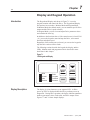
Display and Keypad Operation
Introduction
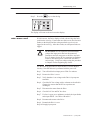
The Keypad and Display unit shown in Figure 7.1 is used to
program, monitor and control the Drive. The Keypad and Display
unit operates in two modes: Monitor Mode and Program Mode.
In Monitor Mode (the default mode), you can monitor specific Drive
outputs and the Drive’s speed reference.
In Program Mode, you can view and adjust Drive parameter values
and examine the error log.
n addition to the functions above, if the control source is local (F-00
= 0), you use the keypad to start and stop the Drive, select motor
direction, and adjust speed.
Regardless of the control source selected, you can use the keypad to
stop the Drive and reset Drive faults.
The following sections describe the keypad, the display, and the
LEDs. Monitor mode and program mode are described in more
detail later in this chapter.
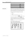
Figure 7.1
1302 Keypad and Display
RPM
%Load
Volts
Remote
Display Description
RUN
Program
Forward
Reverse
Mode
Enter
Forward
Reverse
START
STOP
RESET
The display is a four-character, seven-segment LED. At Drive
power up, SELF is displayed while the Drive performs power-up
diagnostics. During Drive operation, the display indicates parameter
numbers, parameter values, fault codes, and Drive output values.
Figures 7.3 and 7.4 show sample displays.
Publication 1302-5.0 — January, 1998
7–2
Display and Keypad Operation
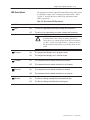
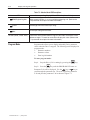
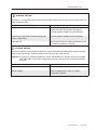
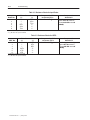
Key Description
The keypad’s six membrane keys are used to monitor, program, and
control the Drive. Table 7.A describes the keys.
Table 7.A - Key Descriptions
- .# ( ,,)1 % 3- .)
D . * .#,)/"# .# ,$0 *,' . ,- ( ,,), &)" 1# ( .# ,$0 $- $( *,)",'
') D (, - ), , - *,' . ,- (/' ,$ 0&/ ), -../- $( *,)",' ') D (, - ), , - .# $(. ,(& -*
& . ), , ! , ( 1# ( 4 )(.,)& )/,
)& )1( .# - % 3- .) $(, - .# -,)&& -*
- .# % 3 .)
Mode
Enter
D 0( .#,)/"# # ')($.), $-*&3 $. ' $( ')($.), ') D & . *,)",' ') 1# ( .# ,$0 $- -.)** D $-*&3 *,' . , 0&/ $( *,)",' ') D 0 *,' . , 0&/ $( *,)",' ') # % 3 *,)0$ - .# - !/(.$)(- , ",& -- )! .# )(.,)& -)/,
- & . &)& ), , '). Forward
Reverse
START
- .# % 3 .) - & . .# $, .$)( )! ').), -#!. ,)..$)(
1# ( .# )(.,)& -)/, $- &)& 4 - .# % 3 .) **&3 *)1 , .) .# ').), 1# ( .# )(.,)& -)/, $- &)&
4 # ( .#$- % 3 $- *, -- ( .# , , () .$0 !/&.- .# ,$0 1$&& & ,. .)
.# &-. *,)",'' !, +/ (3 - .*)$(. -* - .# % 3 .)
STOP
RESET
D /,( )!! .# ,$0 )/.*/. .) .# ').), $! .# ,$0 $- ,/(($("
D & , ,$0 !/&.- 1# ( .# ,$0 $- $( *,)",' ') D 2$. *,)",' ') # ( .#$- % 3 $- *, -- .# ,$0 1$&& ,'* .) , -. . /- ,4 !$( ,. /- ,
)*.$)( ), )-. .) , -. !/&. #$- % 3 -.)*- .# ,$0 , ",& -- )! .# - & . )(.,)& -)/, , '). ), &)&
Publication 1302-5.0 — January, 1998
Display and Keypad Operation 7–3
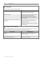
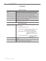
LED Descriptions
The keypad area contains eight LEDs that indicate either Drive status
or which Drive output value is displayed in monitor mode. Tables
7.B and 7.C describe the Drive status LEDs and monitor mode
LEDs, respectively.
Table 7.B - Drive Status LED Descriptions
Run
On
The Drive is generating an output voltage and frequency.
Off
The drive is not generating an output voltage and frequency.
!
Program
Forward
Reverse
Remote
ATTENTION: DO NOT use the RUN LED as an
indication that no line voltage is present in the Drive.
Verify there is no voltage present at the DC bus terminals
(+) and (–) before servicing the Drive. Failure to observe
this precaution could result in severe bodily injury or loss
of life.
On
The keypad and display are in program mode.
Off
The keypad and display are in monitor mode.
On
The requested motor rotation direction is forward.
Off
The requested motor rotation direction is not forward.
On
The requested motor rotation direction is reverse.
Off
The requested motor rotation direction is not reverse.
On
The Drive is being controlled from the terminal strip.
Off
The Drive is being controlled from the keypad.
Publication 1302-5.0 — January, 1998
7–4
Display and Keypad Operation
Table 7.C - Monitor Mode LED Descriptions
LED
Corresponding Display When LED is On (Actual Value)
# #& # # (
$($& '% # $& # )'&,'% # #& # )# ( & ($ (
, %&"(& '& %( $# $& "$& #$&"( $#
$
&#( $ & * )!! !$ "%' &( #
$!('
& * $)(%)( *$!( ($ ( "$($&
!! ' $ $!('
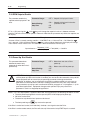
Program Mode
!) $ ( ( * '% &&# ' #! ' ($ $ ( ($(! '!
&&# &# ,
")'( '( ($ ($ '%!+ ( ' *!) & ($ (
,
%&"(& '& %( $# $& "$& #$&"( $#
Program mode allows you to display and modify Drive parameter
values when the Drive is stopped. The following can be displayed in
program mode:
•
Parameter numbers
•
Parameter values
•
Error log information
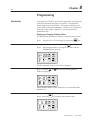
To enter program mode:
Step 1. Stop the Drive (if it is running) by pressing the
Step 2. Press the
Mode
Enter
STOP
RESET
key.
key until the PROGRAM LED turns on.
key or
key to
Parameter F-00 will be displayed. Use the
scroll through the parameter list. The error log follows parameter
F-49 and precedes parameter F-00 as shown in Figure 7.2.
Publication 1302-5.0 — January, 1998
Display and Keypad Operation 7–5
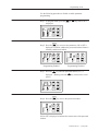
Figure 7.2 - 1302 Menu Structure
F-00
F-01
F-02
F
F
F
F-49
Err
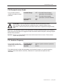
To exit program mode:
Step 1. Press the
Mode
Enter
key until a parameter number or ERR is
displayed.
Step 2. Press the
STOP
RESET
Pressing the
key until the PROGRAM LED turns off.
STOP
RESET
key while you are examining the error
log clears the log.
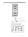
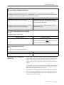
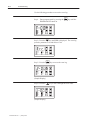
A sample program mode display is shown in Figure 7.3.
Figure 7.3 - Example of a Program Mode Display
RPM
RUN
%Load
Program
Volts
Forward
Remote
Reverse
Mode
Enter
Forward
Reverse
START
STOP
RESET
Publication 1302-5.0 — January, 1998
7–6
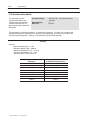
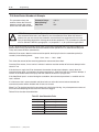
Display and Keypad Operation
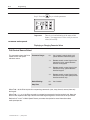
For information about:
Monitor Mode
Refer to chapter:
Displaying or changing parameter values
8
Ensuring program security
8
Individual parameters
8
Accessing the error log
9
Monitor mode is the keypad and display’s default mode of operation
(in other words, the keypad and display will return to monitor mode
when you exit program mode). The keypad and display must be in
monitor mode before the Drive can be put into run (RUN LED is on)
and will remain in monitor mode while the Drive is running.
The following output data can be displayed in monitor mode:
•
RPM
•
% Load
•
Volts
•
Percent Selected Speed Reference (if F–13 = ON)
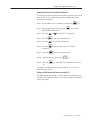
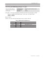
To select a value to monitor, press the
Mode
Enter
key until the LED turns
Mode
on next to the desired display item. Pressing the Enter key will
advance you through each of the displays. (Note that all the LEDs
will turn on to indicate the percent selected speed reference display if
parameter F-13 is set to ON. Refer to the scaling the rpm section of
this Chapter.)
A sample monitor mode display is shown in Figure 7.4
Figure 7.4 - Example of a Monitor Mode Display
Publication 1302-5.0 — January, 1998
RPM
RUN
%Load
Program
Volts
Forward
Remote
Reverse
Mode
Enter
Forward
Reverse
START
STOP
RESET
Display and Keypad Operation 7–7
Displaying the Percent Selected Speed Reference
To display the percent selected speed reference, parameter F-13 must
be set to ON. Use the following procedure to display the percent
selected speed reference:
Step 1. Stop the Drive (if it is running) by pressing the
Step 2. Enter program mode by pressing the
PROGRAM LED turns on.
Step 3. Press the
Step 4.. Press the
or
Mode
Enter
Mode
Enter
STOP
RESET
key.
key until the
key until F-13 is displayed.
key to access the parameter.
key until ON is displayed.
Step 5.. Press the
Mode
Step 6.. Press the Enter key to save the value. (F-13 will be
displayed.)
Step 7.. Press the
STOP
RESET
key to exit program mode.
Step 8.. Start the Drive by pressing the
Step 9.. Press the
on.
Mode
Enter
START
key.
key until all three monitor mode LEDs are
The display will show the active speed reference as 1 to 100% of
maximum speed (F-04).
Scaling the RPM Display and Reference Using F–08
The RPM display and reference can be scaled to an engineering unit
to match your application. Refer to the F-08 description in Chapter 8
for this procedure.
Publication 1302-5.0 — January, 1998
7–8
Display and Keypad Operation
Drive Control
When the control source is the local keypad (F-00 = 0), the keypad is
used to control the Drive. This means that the Drive will respond to
START, STOP/RESET, and FORWARD/REVERSE commands only
from the keypad. The functions of the keypad keys are described in
section 7.2. Refer to the F-00 Control Source Select parameter
description in Chapter 8 for more information on selecting a Drive
control source.
Changing the Reference Using the Keypad
he speed reference can be increased or decreased using the
or
key when F-00 = 0 or 2. The display will show the internal
speed reference in hertz (Hz) while the keys are pressed. There will
be a slight delay before the display returns to the active monitor
mode.
Note that changing the drive’s internal speed reference using the
or
key when the Drive is under remote control will have no
operational effect on the Drive (unless F-00 = 2)
Publication 1302-5.0 — January, 1998
Chapter
8–1
8
Programming
Introduction
To program the 1302 Drive for a specific application, you display the
appropriate parameter and adjust it as required. The parameters
specify characteristics of the Drive. This chapter describes how to
access, display, and modify parameters. Parameters are described in
detail later in this chapter. Appendix C lists the parameters in
alphabetical order.
Displaying or Changing Parameter Values
Use the following procedure to display or change parameter values:
Step 1. Stop the Drive (if it is running) by pressing the
Step 2. Enter program mode by pressing the
PROGRAM LED turns on.
RPM
RUN
%Load
Program
Volts
Forward
Remote
Reverse
Mode
Enter
Forward
Reverse
START
STOP
RESET
Mode
Enter
STOP
RESET
key.
key until the
The first parameter number (F-00) will be displayed.
Step 3 Press the
or
number is displayed.
RPM
RUN
%Load
Program
Volts
Forward
Remote
Reverse
Mode
Enter
Forward
Reverse
START
STOP
RESET
key until the desired parameter
Each parameter number will be displayed as you scroll through the
parameter list.
Step 4. Press the
RPM
RUN
%Load
Program
Volts
Forward
Remote
Reverse
Mode
Enter
key to display the parameter value.
Mode
Enter
Forward
Reverse
START
STOP
RESET
Publication 1302-5.0 — January, 1998
8–2
Programming
Step 5 .Press the
RPM
RUN
%Load
Program
Volts
Forward
Remote
Reverse
or
Mode
Enter
Forward
Reverse
START
STOP
RESET
key to change the value.
Note that if programming has been disabled in parameter F-20
(Password Lockout Enable), the value will not change. Refer to
Chapter 8, Ensuring Program Security, for more information.
Step 6. Press the
RPM
RUN
%Load
Program
Volts
Forward
Remote
Reverse
Mode
Enter
key to save the changed value.
Mode
Enter
Forward
Reverse
START
STOP
RESET
The parameter number is displayed again.
To display or change additional parameters, repeat steps 3
through 6.
To exit program mode, press the
Mode
Enter
key until a parameter
number or ERR is displayed; then press the
STOP
RESET
key.
Important: Parameter values and the keypad status (local or
remote) are retained through a line dip or power loss.
Program Security
!
ATTENTION: It is your responsibility to determine how
to distribute the password. Allen–Bradley is not
responsible for unauthorized access violations within the
user’s organization. Failure to observe this precaution
could result in equipment damage or bodily injury.
Parameter values can be password-protected using parameter F-20
(Password Lockout Enable). When F-20 is set to ON, parameter
values can be displayed but cannot be modified from the keypad
unless the correct password is entered in F-20.
Note: The password is factory set to 257 and cannot be modified by
the user.
Publication 1302-5.0 — January, 1998
Programming 8–3
Use the following procedure to disable or enable parameter
programming:
Step 1. In program mode, press the
displayed.
RPM
RUN
%Load
Program
Volts
Forward
Remote
Reverse
Mode
Enter
Forward
Reverse
START
STOP
RESET
or
key until F-20 is
Mode
Enter
Step 2. Press the
key to access the parameter. ON or OFF is
displayed to indicate whether the password lockout feature is
currently enabled or disabled.
RPM
RUN
%Load
Program
Volts
Forward
Remote
Reverse
Mode
Enter
START
Forward
Reverse
STOP
RESET
Programming Enabled
RPM
RUN
%Load
Program
Volts
Forward
Remote
Reverse
Mode
Enter
Forward
Reverse
START
STOP
RESET
Programming Disabled
Step 3. Press the
key until the password number, 257, is
displayed. (Holding down the
key increases the scroll
speed.)
RPM
RUN
%Load
Program
Volts
Forward
Remote
Reverse
Step 4. Press the
RPM
RUN
%Load
Program
Volts
Forward
Remote
Reverse
Mode
Enter
Forward
Reverse
START
STOP
RESET
Mode
Enter
key to save the password number.
Mode
Enter
Forward
Reverse
START
STOP
RESET
ON or OFF is displayed to indicate the current state of the password
lockout.
Publication 1302-5.0 — January, 1998
8–4
Programming
Step 5. Press the
RPM
RUN
%Load
Program
Volts
Forward
Remote
Reverse
Important:
Mode
Enter
key to exit the parameter.
Mode
Enter
Forward
Reverse
START
STOP
RESET
There is no visual indication of the status of this
feature. You must access F-20 to verify its current
value (ON or OFF).
Parameter Descriptions
Displaying or Changing Parameter Values
FĆ00 Control Source Select
This parameter selects the Drive
control source and speed
reference source.
Parameter Range:
0=
Local control; control signals and
speed reference from the keypad
1=
Remote control; control signals from
the terminal strip; speed reference
from the analog input
2=
Remote control; control signals from
the terminal strip; speed reference
from the keypad
3=
Remote control; control signals from
the terminal strip; multiĆspeed presets
from the terminal strip
Default Setting:
0=
Local control
Step Size:
N/A
When FĆ00 = 0, the Drive responds to sequencing commands (start, stop, forward, reverse) from only
the keypad.
When FĆ00 = 1, 2, or 3, the Drive responds to sequencing commands from the terminal strip. Note that
the drive will respond to the stop command from the keypad regardless of the value in this parameter.
Refer to the FĆ23 to FĆ25 MultiĆSpeed Presets parameter description for more information about
multiĆspeed presets.
Publication 1302-5.0 — January, 1998
Programming 8–5
FĆ01 Acceleration Time
This parameter specifies the
Parameter Range:
amount of time it takes the motor Default Setting:
to ramp from stop to the
Step Size:
maximum speed setting in FĆ04.
0.5 to 90 seconds
5.0 seconds
0.10 seconds
If the setpoint frequency requested from the keypad (using the ąą andąą keys) is less than the
maximum speed setting, the time to ramp to that frequency will be proportionally less than the actual
rate setting. For example, if FĆ04 = 60ĂHz and FĆ01 = 4 seconds, it will take 2 seconds to ramp to a
frequency reference of 30 Hz.
Note that if the acceleration rate is set too fast, an overcurrent fault may occur (OC will be displayed).
FĆ02 Deceleration Time
This parameter specifies the
Parameter Range:
amount of time it takes the motor Default Setting:
to ramp from the maximum
Step Size:
speed setting in FĆ04 to a stop.
0.5 to 90 seconds
5.0 seconds
0.10 seconds
If the frequency requested from the keypad (using the ąą andąą keys) is less than the maximum
speed setting, the time to ramp to that frequency will be proportionally less than the actual rate setting.
For example, if FĆ04 = 60ĂHz and FĆ02 = 4 seconds, it will take 2 seconds to ramp to a frequency
reference of 0ĂHz from 30 Hz.
Note that if the deceleration rate is set too fast, a high bus fault may occur (HU will be displayed).
FĆ03 Minimum Speed
This parameter limits the speed
reference to the Drive.
Regardless of what speed
reference is supplied, the
regulator will not command a
speed less than the value in
FĆ03.
!
Parameter Range:
Default Setting:
Step Size:
0.5 to 30 Hz
5.0 Hz
0.10 Hz if FĆ04 < 100 Hz
0.25 Hz if FĆ04 ≥ 100 Hz
ATTENTION: The 1302 Drive is intended to operate the motor at a predetermined
minimum speed unless disconnected from the power source. The user is responsible for
assuring safe conditions for operating personnel by providing suitable guards, audible or
visual alarms, or other devices to indicate that the drive is operating at minimum speed,
(possibly zero speed), or the user must verify that the motor output shaft will rotate at all
combinations of load and output speed required by the application.
Publication 1302-5.0 — January, 1998
8–6
Programming
FĆ04 Maximum Speed
This parameter limits the speed
reference to the Drive.
Regardless of what speed
reference is supplied, the
regulator will not command a
speed greater than the value in
FĆ04.
!
Parameter Range:
Default Setting:
Step Size:
30 to 240 Hz
60 Hz
0.10 Hz if FĆ04 < 100 Hz
0.25 Hz if FĆ04 ≥ 100 Hz
ATTENTION: The user is responsible for ensuring that driven machinery, all driveĆtrain
mechanisms, and process line material are capable of safe operation at maximum speed
(FĆ04). Failure to observe this precaution could result in bodily injury or equipment damage.
FĆ05 Current Limit
This parameter limits motor
output torque while it is running
or accelerating.
Parameter Range:
Default Setting:
Step Size:
10% to 150% of rated drive current
150%
1.0%
When output current attempts to exceed the preset current limit, motor current will be maintained or
reduced, or the acceleration / deceleration time will be extended. If current limit is set too low or too high
relative to the required load, an overcurrent fault may occur (OC will be displayed).
Publication 1302-5.0 — January, 1998
Programming 8–7
FĆ06 Manual Torque Boost
This parameter sets the
percentage of output voltage
boost at zero frequency.
Parameter Range:
Default Setting:
Step Size:
0 to 10%
2%
1%
Torque boost offsets the voltage drop of the AC motor at low speeds. For high friction loads or high
inertia loads, a high starting torque level may be needed. Manual torque boost is only effective at speeds
lower than oneĆhalf of the motor's base frequency. See Figure 8.1.
When adjusting this parameter, start with the default setting of 2% and gradually increase the value until
motor operation is satisfactory. If torque boost is set too high relative to the load and acceleration rate,
an overcurrent fault may occur (OC will be displayed).
OUTPUT VOLTAGE (%)
Figure 8.1 - Manual Torque Boost Adjustment Range
100
50
10
Manual Torque Boost
0
Base Speed
Base Speed
2
FREQUENCY (Hz)
FĆ07 V/Hz (Base Speed)
This parameter specifies the
base speed at maximum output
voltage and is used to establish
the volts/hertz (V/Hz) curve.
Parameter Range:
Default Setting:
Step Size:
30 to 240 Hz
60 Hz
1.0 Hz
The V/Hz curve allows the Drive to maintain a constant V/Hz ratio, providing constant torque at any
frequency. See Figure 8.2.
Figure 8.2 - Volts/Hertz Curve
Output Voltage (%)
100
0
Base
Frequency
240
FREQUENCY (Hz)
Publication 1302-5.0 — January, 1998
8–8
Programming
FĆ08 RPM at Base Speed
This parameter scales the RPM
display and the setpoint to a
userĆspecified engineering unit.
Parameter Range:
Default Setting:
Step Size:
10 to 9999
1750
1.0 unit
This parameter defines the scaling value applied to the current speed before it is displayed. It is also
used to scale the local reference when FĆ18 is set to ON.
The value to enter into FĆ08 is the maximum value (in RPM, hertz, or any other engineering unit) to be
displayed when the Drive is running at base speed (FĆ07).
Display Scaling Examples
Example 1: Assume that an application requires the display show 1750 RPM when the drive is running
at a base speed of 60 Hz. The RPM display is scaled according to the following equation:
Present Operating Speed (Hz) FĆ08 + Displayed Value
FĆ07
At 30 Hz, the RPM display will show 875:
30 Hz
1750 + 875
60
Example 2: Assume the application requires the display show 20 feet per minute for a conveyor (or 20
gallons per minute for a pump) when the motor is running at base speed (FĆ07= 60 Hz). Enter 20 in
parameter FĆ08 to scale the display.
At 30 Hz, the display will show 10 feet (or gallons) per minute:
30 Hz 20 + 10
60
Publication 1302-5.0 — January, 1998
Programming 8–9
FĆ09 Configurable Output Relay Select
This parameter specifies the type Parameter Range:
of status indication the output
relay contacts provide (terminals
14, 15, and 16 on the Drive
terminal strip).
0 = Output relay is energized to show
state of Drive running.
1 = Output relay is energized to show
state of active fault (IET).
2 = Output relay is energized to show
state of Drive running at speed.
Default Setting:
Step Size:
0
N/A
If FĆ09 = 0, the output is energized only when the RUN LED is on.
If FĆ09 = 1, the output remains energized until the fault is cleared by pressing the
operation) or by using the remote IET reset signal (for remote operation).
STOP
RESET
key (in local
If FĆ09 = 2, the output is energized when the Drive is running and at speed.
FĆ10 Carrier Frequency
This parameter selects the
Drive's carrier frequency.
Parameter Range:
Default Setting:
Step Size:
4 = 4 kHz Carrier frequency
6 = 6 kHz Carrier frequency
8 = 8 kHz Carrier frequency
4
N/A
The carrier frequency controls the width of the pulse and keeps the current smooth to the motor. This
parameter can compensate for acoustic noise, heating, and other current problems by adjusting the
switching frequency of the transistors in the inverter section.
Keeping the carrier frequency at 4kHz maximizes the continuous power rating of the Drive with,
generally, an acceptable acoustic noise level from the motor. Increasing the carrier frequency reduces
the acoustic noise, but in some applications this can result in derating of the Drive output amps.
Publication 1302-5.0 — January, 1998
8–10
Programming
FĆ11 Remote Reference Gain
This parameter scales the
maximum remote speed
reference to match external
equipment.
Parameter Range:
Default Setting:
Step Size:
60% to 100% of full scale maximum
reference
100%
0.10%
Normally, the maximum speed reference (the amount of reference at maximum speed, FĆ04) is either 10
VDC or 20 mA. The reference gain is used to scale the speed reference to another value (for example,
9.5 VDC or 19 mA). Enter the parameter value in percent of full scale reference.
To calculate the scaled reference if you are using a 0 to 20 mA remote reference, use the following
equation:
Desired Maximum Reference (mA) x 100 = % gain (mA reference)
Reference Range (20)
Example
If the remote speed reference is 0 to 20 mA and the maximum reference required is 19.2 mA, scale as
follows:
19.2
x 100 = 96% gain
20
To calculate the scaled reference if you are using a 0 to 10 VDC remote reference, use the following
equation:
Desired Maximum Reference (VDC) x 100 = % gain (VDC reference)
Reference Range (10)
Example
If the remote speed reference is 0 to 10VDC and the maximum reference required is 9.5 VDC, scale as
follows:
9.5
x 100 = 95% gain
10
Publication 1302-5.0 — January, 1998
Programming 8–11
FĆ12 Remote Reference Offset
This parameter scales the
remote speed reference (0 to
10VDC or 0 to 20 mA) to a
minimum value.
Parameter Range:
Default Setting:
Step Size:
0% to 40% of full scale minimum reference
0%
0.10%
Typically, the value of the minimum speed reference (the amount of reference at minimum speed, FĆ03) is
either 0 VDC or 0 mA. Enter the parameter value as a percentage of the full scale reference to be offset from
minimum speed.
To calculate the scaled minimum reference, use the following equation:
Desired Minimum Speed Offset
Reference Range
100 + %offset
Scaling Examples
Example 1: If the remote analog input speed reference is 0 to 20 mA (J6 set on terminals 2 and 3), and
the available analog reference signal is 4 to 20 mA, use FĆ12 to obtain minimum speed with minimum
analog input as follows:
4 x 100 = 20% offset
20
Example 2: If the remote analog input speed reference is 0 to 10 VDC (J6 set on terminals 1 and 2), and
the available signal is offset 0.4 VDC, use FĆ12 to obtain minimum speed with minimum analog input as
follows:
0.4 x 100 = 4% offset
10
FĆ13 Percent Selected Speed Reference Display Enable
This parameter enables or
disables the fourth monitor
mode display.
Parameter Range:
ON =
Fourth monitor mode display is
enabled.
Default Setting:
Step Size:
OFF = Fourth monitor mode display is
disabled.
OFF
N/A
Mode
If FĆ13 = ON, the current value of the active speed reference can be displayed by pressing the Enter key
(while the Drive is running) until all three monitor mode LEDs are on. The active speed reference is
displayed as 1 to 100% of maximum speed (FĆ04).
If FĆ13 = OFF, the active speed reference will not be displayed.
Refer to Chapter 3 for more information on the monitor mode displays.
Publication 1302-5.0 — January, 1998
8–12
Programming
FĆ14 Electronic Thermal Overload
This parameter sets the trip level
for the electronic thermal
overload fault (OL) when
FĆ15 = ON.
Parameter Range:
Default Setting:
Step Size:
20% to 100% rated current
100%
1%
This parameter should be adjusted if the motor current rating is less than the Drive current rating.
Use the formula below to calculate the setting level as a percentage of maximum continuous current:
FĆ14 =
Motor Full Load Current
Drive Output Rated Current
x 100
The motor full load current value can be found on the motor nameplate. See Table 2.A or the Drive
nameplate for the Drive rated output value.
FĆ15 Electronic Thermal Overload Enable
This parameter enables or
disables the electronic motor
thermal overload function. This
function operates like a motor
thermal switch to protect the
motor from overheating.
!
Parameter Range:
OFF = No electronic thermal overload
protection.
ON =
Default Setting:
Step Size:
ON
N/A
Electronic thermal overload
protection is active.
ATTENTION: Parameter FĆ15 must be set to ON in single motor applications to guard against
damage from overheating or combustion of surrounding materials. Failure to observe this
precation could result in fire or damage to or destruction of the motor and the drive.
When FĆ15 = ON, the Drive faults if it exceeds the thermal overload time (60 seconds at 150% of FĆ14).
When an external thermal switch or other overtemperature monitoring device is connected to the function
loss circuit (terminals 10 and 11), this parameter may be set ON or OFF.
For multiĆmotor applications, set this parameter to OFF. The individual motors must have thermal switch
protection.
Publication 1302-5.0 — January, 1998
Programming 8–13
FĆ16 Coast Stop Enable
* ')$+) *#+* &. +
$&+&) . ## *+&' .% -% *+&' &$$%
!
Parameter Range:
%# &*+ *+&' $&+&) . ##
&*+ +& )*+
Default Setting:
Step Size:
*# &*+ *+&' $&+&) . ##
)$' +& )*+
ATTENTION: &, $,*+ ')&- % /+)%# ). ) $)%0 *+&' ), + &,+* & +
) - ), +)0 * ), + $,*+ *# + *0*+$ % * & $')&') &')+ &% %&%+)&##
$ % &')+ &% $0 )*,#+ + * ')&,) * %&+ &##&. #,) +& &*)- + *
'),+ &% &,# )*,#+ ) - &) (, '$%+ $ & #0 %!,)0 &) +
&*+1+&1)*+ *+&' +,)%* & + +)%* *+&) '&.) - ) -)* )$'1+&1)*+ *+&' )* + +)%* *+&)
'&.) - ) -)* ,%+ # + $&+&) &$* +& *+&' % +% +,)%* & + '&.) - ) -)*
&+ ++ + ,%+ &% #&** %',+ &'% % &) ) - ,#+ . ## #.0* ,* &*+1+&1)*+ *+&'
FĆ17 Reverse Disable
* ')$+) %#* &)
*#* )-)* )&++ &% & +
$&+&)
Parameter Range:
Default Setting:
Step Size:
*# )-)*
%# )-)*
1
+ &).))-)* %',+ ##&.* &).) &) )-)* )&++ &% & + $&+&)
Forward
1
)-)* )&++ &% & + $&+&) * ')& + % 1
')** % + Reverse "0 &% +
"0' % #&# &%+)&# &) . ) % +& +)$ %# &% + +)$ %# *+) ' % )$&+ &%+)&# &* %&+ + ) -
&')+ &%
Publication 1302-5.0 — January, 1998
8–14
Programming
FĆ18 RPM Setpoint Enable
The parameter enables the
setpoint to be displayed in FĆ08
units.
Parameter Range:
Default Setting:
Step Size:
OFF = Setpoint is displayed in hertz.
ON =
ON
N/A
Setpoint is displayed in the units
specified in FĆ08.
If FĆ18 = ON, pressing the
and
keys will change the setpoint in units of 1 between minimum
speed in FĆ08 units and maximum speed in FĆ08 units. Note that this parameter only affects the setpoint, not
the display.
Example
Assume a Drive is currently running at 60 Hz = 1750 RPM, FĆ08 = 1750, and FĆ10 = ON. When the
key is pressed, 1750 is displayed. When the
key is pressed three more times, the display will change
from 1750 to 1749 to 1748 to 1747. The reference is then rescaled based on this input:
Input reference +
Reference (1747)
FĆ08Ă(1750)
FĆ04Ă(60Hz) + 59.89 Hz
FĆ19 PowerĆUp Start Enable
This parameter determines
whether the motor starts
automatically when the Drive is
powered up.
!
Parameter Range:
Default Setting:
Step Size:
OFF = Motor does not start at Drive
power up.
ON =
OFF
N/A
Motor starts at Drive power up.
ATTENTION: Setting FĆ19 = ON causes output power to be applied to the motor automatically
at Drive power up. When this function is enabled, you must ensure that automatic start up of the
driven equipment will not cause injury to operating personnel or damage to the driven
equipment. In addition, you are responsible for providing suitable audible or visual alarms or
other devices to indicate that this function is enabled and the Drive may start at any moment.
This parameter may only be used as outlined in NFPA79, paragraph 6-14 (exceptions 1-3) for
specialized applications. Equipment damage and/or personal injury may result if this
parameter is used in an inappropriate application.
When FĆ19 = ON, output power is applied to the motor at drive power up if the following conditions are met:
D The drive powerĆup diagnostics must be passed (SELF will be displayed at power up).
D No faults can be active.
D The terminal strip function loss input must be closed.
D The frontĆpanel keypad
STOP
RESET
key must not be pressed.
If the Drive is under local control, it will effectively simulate a start signal to start the Drive.
If the Drive is under remote control, the Drive will start only if the terminal strip START input is asserted.
Publication 1302-5.0 — January, 1998
Programming 8–15
FĆ20 Password Lockout Enable
This parameter enables or
disables parameter password
protection.
Parameter Range:
ON =
Default Setting:
Step Size:
!
OFF = Password lockout disabled
(parameters can be modified)
OFF
N/A
Password lockout enabled
(parameters cannot be modified)
ATTENTION: It is your responsibility to determine how to distribute the password.
Allen-Bradley is not responsible for unauthorized access violations within the user's
organization. Failure to observe this precaution could result in equipment damage or bodily
injury.
When FĆ20 = ON, parameter values can be displayed but cannot be modified (except FĆ20). Entering the
factoryĆset password number (257) toggles the state of the lockout. Refer to Chapter 8, Ensuring Program
Security for this procedure.
Important: There is no visual indication of the status of this feature. You must access FĆ20 to verify its
current value (ON or OFF).
FĆ21 Avoidance Frequency
This parameter specifies the
midpoint of the avoidance band
selected in FĆ22.
Parameter Range:
Default Setting:
Step Size:
Minimum speed to maximum speed (Hz)
5.0
0.10 Hz
The avoidance band can help alleviate problems with vibrations/harmonics at a specific operating
frequency of the driven motor or machinery. Refer to the FĆ22 parameter description for more
information.
Publication 1302-5.0 — January, 1998
8–16
Programming
FĆ22 Avoidance Bandwidth
' $&!(& '(' (
*#" "+( "&%)"- (( ' +(" (
*#" " &') (' " "&( &%)"- #+ (
"+(
Parameter Range:
(# . *#" &%)"' .
Default Setting:
Step Size:
' $&!(& ' )' +( $&!(& / *#" &%)"- &* " &( "
&( (&#) ( *#" " #+*& ( ""#( #$&( ( '(- '(( ( "- # (
*#" " &%)"' ((" / (# ' ' ( *#" &%)"-
Example
'')!
"!)! $ / .
,!)! $ /
.
*#" &%)"- / .
*#" "+( / .
*#" " (# .
Requested Output
Frequency
.
.
.
.
.
.
.
.
Publication 1302-5.0 — January, 1998
Output Frequency After
Avoidance Band Correction
.
.
.
.
.
.
.
.
Programming 8–17
FĆ23, FĆ24, and FĆ25 MultiĆSpeed Presets 1, 2, and 3
These parameters allow the
setting of up to three different
preset speeds.
Parameter Range:
Default Setting:
Step Size:
Minimum speed to maximum speed
20 Hz
0.10 Hz
Setting FĆ00 = 3 (multiĆspeed configuration) reconfigures the terminal strip control inputs as follows:
Terminal 6 = START/STOP/IET RESET (open = STOP; closed = IET RESET/START)
Terminal 7 = MSPD 1
Terminal 8 = MSPD 0
Refer to Chapter 5.
Terminals 7 and 8 are used to select the reference source as shown in Table 8.A
Table 8.A - Multi-Speed Presets Digital Inputs
MSPD 1
Open (0)
Open (0)
Closed (1)
Closed (1)
MSPD 0
Open (0)
Closed (1)
Open (0)
Closed (1)
Reference Source
Terminal strip analog input (variable speed)
MultiĆSpeed #1 (FĆ23)
MultiĆSpeed #2 (FĆ24)
MultiĆSpeed #3 (FĆ25)
Publication 1302-5.0 — January, 1998
8–18
Programming
FĆ26 AutoĆRestart Number of Attempts
This parameter selects the
number of times the Drive will
attempt to restart after certain
faults have shut down the Drive.
!
Parameter Range:
Default Setting:
Step Size:
0 to 10
0
N/A
ATTENTION: If parameter FĆ26 ≠ 0, the Drive will attempt to restart automatically after
autoĆrestartable drive faults (see Table 8.B) have shut down the Drive. When this feature is
enabled, the you must ensure that automatic restart of the driven equipment will not cause
injury to operating personnel or damage to the driven equipment. This parameter may only be
used as outlined in NFPA79, paragraph 6-14 (exceptions 1-3) for specialized applications.
If FĆ26 ≠ 0, the Drive logs and resets certain faults (called autoĆrestartable faults and listed in table 8.2) it
detects while running. The Drive then waits the amount of time specified in FĆ27 (AutoĆRestart Retry Wait
Time) and restarts the Drive automatically.
While the Drive counts down the autoĆrestart time period, the display flashes the countdown period (in
seconds) in the following format:
Ar30 .. Ar29 .. Ar28 ...... Ar01 .. Ar00"
This shows the amount of time remaining before the autoĆrestart takes effect.
Once the Drive restarts, it must run for 5 minutes in order to reset the number of fault reset attempts to the
value in FĆ26.
If the fault occurs again, the Drive decrements the number of autoĆrestart attempts, counts down the
autoĆrestart time again, and continues the autoĆrestart process. If the Drive faults on all of these attempts, it
remains in the faulted state and displays the fault code for the fault it is trying to clear.
If the Stop/Reset input is asserted during the countdown, the autoĆrestart procedure is cancelled and the
fault is latched.
If a fault occurs that is autoĆrestartable and other faults are active that are not autoĆrestartable, the
autoĆrestart function will be disabled until all faults are cleared.
When FĆ26 ≠ 0, the drive logs the first occurrence of a fault in the fault log. Any subsequent occurrence of
that fault while attempting to restart the Drive will not be logged.
Table 8.B lists the autoĆrestartable faults.
Table 8.B - Auto-Restartable Faults
Fault Code
HU
LU
OC
OH
OL
Publication 1302-5.0 — January, 1998
Description
High bus voltage
Low bus voltage
Overcurrent
Thermostat/drive overload
Electronic thermal overload
Programming 8–19
FĆ27 AutoĆRestart Retry Wait Time
This parameter specifies the
amount of time the Drive will wait
between autoĆrestart attempts.
Parameter Range:
Default Setting:
Step Size:
1 to 30 seconds
1
1.0 second
This parameter is used with parameter FĆ26 (AutoĆRestart Number of Attempts). Refer to the FĆ26
parameter description for information regarding this feature.
FĆ28 Drive Voltage Selection
This parameter displays the
drive's voltage rating.
!
Parameter Range:
Default Setting:
Step Size:
N/A
N/A
N/A
ATTENTION: This parameter is set at the factory and must not be changed by the user.
Failure to observe this precaution could result in damage to, or destruction of, the equipment.
FĆ29 Analog Output Select
This parameter selects which
monitor mode value is directed
to the analog output (regardless
of which monitor mode value is
displayed).
Parameter Range:
SPd =
Current RPM/speed output
LOAd = Current percent load output
Default Setting:
Step Size:
UOL =
Current calculated output voltage
rEF =
Current percent of selected
reference
SPd
N/A
Refer to Table A.E in Appendix A for more detail about the analog output.
FĆ49 Version Information
This parameter displays the
software version.
Parameter Range:
Default Setting:
Step Size:
N/A
N/A
N/A
Publication 1302-5.0 — January, 1998
8–20
Programming
This Page Intentionally Blank
Publication 1302-5.0 — January, 1998
Chapter
9–1
9
Troubleshooting
!
Introduction
ATTENTION: Only qualified personnel familiar with
the 1302 Drive and associated machinery should perform
troubleshooting or maintenance functions on the Drive.
Failure to comply may result in personal injury and/or
equipment damage.
The 1302 Drive is monitored by internal diagnostics. If a fault
occurs, the Drive displays a two-digit fault code to identify the
problem. A fault causes the Drive to coast to rest if it is running or
prevents the Drive from starting if it is stopped. The fault code is
also entered into the error log.
This chapter defines the fault codes and suggests actions to correct
problems. It also describes how to access and clear the error log.
Note:
Refer also to the F-26 (Auto-Restart Number of Attempts)
parameter description in Chapter 8. This describes the
Drive’s reaction to Drive faults if the auto-restart feature is
enabled (F-26 p 0).
Important: Before servicing the Drive, verify that the DC bus
capacitors have discharged as described in the following paragraph
Use an isolated multimeter to measure the DC bus voltage and to
make resistance checks. Note that dedicated troubleshooting test
points are not provided.
Verifying DC Bus Voltage
!
ATTENTION: DC bus capacitors retain hazardous
voltages after input power has been disconnected.
Disconnect and lock out power to the Drive and wait five
(5) minutes for the DC bus capacitors to discharge.
Failure to disconnect power could result in death or
serious injury. Verify bus voltages using the procedure in
the following paragraph before beginning any checks.
The 1302 Drive’s DC bus capacitors retain hazardous voltages after
input power has been disconnected. Perform the following steps
before touching any internal component
Step 1. Turn off, lock out, and tag input power to the Drive. Wait
five minutes.
Step 2. Remove the Drive’s cover.
Step 3. Verify that there is no voltage at the Drive’s input power
terminals.
Publication 1302-5.0 — January, 1998
9–2
Troubleshooting
Step 4. Measure the DC bus voltage at the DC bus power terminals
with a multimeter while standing on a non-conductive
surface and wearing insulated gloves (600V). See Figure
9.1.
Once the Drive has been serviced, reattach the Drive’s cover and
reapply input power.
Figure 9.1 - DC Bus Terminals
Troubleshooting the Drive
Using Fault Codes
Table 9.A defines the fault codes for user-correctable faults, lists
possible causes, and suggests actions to take to correct the problem.
All other faults require replacement of the drive.
If a fault occurs, do the following:
STOP
Step 1. Try to clear the fault first by pressing the RESET key or
asserting the IET reset input (remote operation). If the fault
reoccurs, continue with step 2.
Step 2. Refer to Table 9.A to identify the fault code and the possible
causes.
Step 3. Perform the suggested corrective action(s).
Step 4. Clear the fault by pressing the
IET reset input.
STOP
RESET
key or asserting the
Table 9.A - Drive Faults and Corrective Actions
= FUNCTION LOSS
Possible Cause
! Publication 1302-5.0 — January, 1998
Corrective Action
! "
Troubleshooting 9–3
= HIGH BUS VOLTAGE
(& & % ") ' '%"! '%# '%&" "' '' ' (' * !"' % (!' ' (& &
"* ' (& )
Possible Cause
%'"! %' &''! ! , & '"" &'
Corrective Action
%& ' %'"! %' ! , % '"
#'% "% ' , #% '% &%#'"!
!&' ' "#'"! &!(% %&&'"% %! '
%) *& &'%' !'" "%*%,%(!!! "
'' & !%'
!&' ' "#'"! &!(% %&&'"% %! '
!#(' !
%+ '' ' !#(' & *'! &#'"! !&'
! &"'"! '%!&"% % %$(%
= LOW BUS VOLTAGE
(& )"' & ! "* ' '%"! '%# "* '%&" ) "' '' ' (' * !"' %
(!' ' !#(' ! )"' & *'! ' #%"#% %! & + ' * &"!&
Important: ! # "% " !'%+ #"*% "&& "(%& ! ' (& & '" %& '" ' #%"#%
) *'! & ' %) * ('" '+ %&'%' ' %) *& %(!!! *! ' ('
"(%%
Possible Cause
"&& " !#(' #"*%
Corrective Action
!" ! #"*%
"* ! )"'
!" ! #"*% !&' ! &"'"!
'%!&"% % %$(%
Publication 1302-5.0 — January, 1998
9–4
Troubleshooting
= OVERCURRENT
'+( *''#) ')# ( # -
Possible Cause
$') # ) '+ $*)%*)(
Corrective Action
'. )) ) '+( #%*) # $*)%*) ,'# '
%'$%'!. $##) ' )$ %)' '$*# *!) $#)$#
'. )) ) '+( #%*) # $*)%*) ,'# '
%'$%'!. $##) ' )$ %)' '. )) ) $*)%*) ,'# )$ ) "$)$' ( #$)
$##) )$ '$*# $' #. $)' +$!) ($*'
' )$ %)' #()#)#$*( $+'*''#) '(*!)# # ')
'+ *''#)
#'( ) !')$# )" # / $' )
!')$# )" # / ' )$ %)' $'
%'")' ('%)$#(
*() ) *''#) !") !+! # / ) ( )$$ !$, $'
)$$ '!)+ )$ ) !$ ) *()"#)(
# #'"#)(
= THERMOSTAT / DRIVE OVERLOAD
#)'#! )'"$()) )) -((+ )"%')*'( # ) '+ $) )) ) *!) ,!! #$) !' *#)!
) #)'#! '+ )"%')*' ( ,)# '# ( ". ) , ($#(
Possible Cause
'+( $%')# (%)$#( + #
-
Corrective Action
) %%!)$# # # ) '''
'&*#. # / ' )$ %)' $' )
%'")' ('%)$#
"#) $%')# )"%')*' $ ) '+ (
# - %%#- ) )"%')*' ) ) #()!!)$# () $+
) '+ )$ $$!' !$)$#
Publication 1302-5.0 — January, 1998
Troubleshooting 9–5
= ELECTRONIC THERMAL OVERLOAD
The electronic thermal overload trip level has been exceeded. This fault protects the Drive motor from
overheating due to excessive current within a specified period. Note that the fault will not clear until the input
line voltage is within the proper range. This may take a few seconds.
Possible Cause
The current limit setting in FĆ05 is incorrect.
Corrective Action
If the current limit level is too low relative to load,
increase the current level in FĆ05. Refer to chapter 8
for the parameter description.
The electronic thermal overload setting in FĆ14 does
not match the motor and Drive combination.
Verify the value of FĆ14. Refer to chapter 8 for the
parameter description.
,
= POWER SUPPLY OUT OF RANGE
The power supply is out of range.
Possible Cause
Possible regulator failure.
Corrective Action
Contact Allen-Bradley for assistance if the fault
STOP
reoccurs after pressing the ąą
key (or asserting
RESET
the IET reset input) or cycling power.
= INVALID DRIVE VOLTAGE
The value in FĆ28 is incorrect for the Drive.
Possible Cause
An invalid Drive voltage was selected in FĆ28.
Accessing and Clearing the
Error Log
Corrective Action
Select the voltage to match the input line voltage.
If a fault occurs, the Drive displays a fault code and logs the fault
code into the error log. If more than one fault occurs, the first fault
flashes on the display and the subsequent faults (up to two) are
logged in the error log. After three faults, no subsequent faults are
logged.
The faults in the error log are numbered sequentially. For example, if
an overcurrent fault occurred first followed by a thermal overload
fault, the error log would read 1-OC, 2-OL.
The last fault to occur appears first when the error log is accessed.
For example, if the last fault to occur was a low bus fault, and the
error log contained three entries, the error log would display 3-LU
when the error log is accessed.
Publication 1302-5.0 — January, 1998
9–6
Troubleshooting
Use the following procedure to access the error log:
Step 1. Enter program mode by pressing the
PROGRAM LED turns on.
RPM
RUN
%Load
Program
Volts
Forward
Remote
Reverse
Mode
Enter
Forward
Reverse
START
STOP
RESET
Mode
Enter
key until the
Step 2. Press the
key until ERR is displayed. The error log
precedes parameter F-00 and follows F-49.
RPM
RUN
%Load
Program
Volts
Forward
Remote
Reverse
Mode
Enter
Forward
Reverse
START
STOP
RESET
Mode
Enter
Step 3. Press the
RPM
RUN
%Load
Program
Volts
Forward
Remote
Reverse
key to access the error log.
Mode
Enter
Forward
Reverse
START
STOP
RESET
(Sample Display
Step 4. Press the
RPM
RUN
%Load
Program
Volts
Forward
Remote
Reverse
key to move through the error codes.
Mode
Enter
Forward
Reverse
START
STOP
RESET
(Sample Display)
Publication 1302-5.0 — January, 1998
Troubleshooting 9–7
Step 5.
Press the
RPM
RUN
%Load
Program
Volts
Forward
Remote
Reverse
STOP
RESET
key to clear the log.
Mode
Enter
Forward
Reverse
START
STOP
RESET
The display will return to the active monitor display.
Power Module Check
If a fault occurs, the Drive displays a fault code and logs the fault
code into the error log. If more than one fault occurs, the first fault
flashes on the display and the subsequent faults (up to two) are
logged in the error log. After three faults, no subsequent faults are
logged.
!
ATTENTION: DC bus capacitors retain hazardous
voltage after input power has been disconnected.
Disconnect and lock out power to the Drive and wait
five (5) minutes for the DC bus capacitors to discharge.
Failure to disconnect power could result in death or
serious injury. Verify bus voltages using the procedure
in Chapter 9 before beginning any checks.
Use the following procedure to check the Drive’s Power Module
circuitry. Note that this test is performed with the power off.
Step 1. Turn off and lock out input power. Wait five minutes.
Step 2. Remove the Drive’s cover.
Step 3. Verify that there is no voltage at the Drive’s input power
terminals
Step 4. Check the DC bus voltage with a voltmeter as described in
Chapter 9 to ensure that the DC bus capacitors are
discharged.
Step 5. Disconnect the motor from the Drive.
Step 6. Check all AC line and DC bus fuses.
Step 7. If a fuse is open, use a multimeter to check the input diodes
and output IGBTs. See Tables 9.B and 9.C
Step 8. Reconnect the motor to the Drive.
Step 9. Reattach the Drive’s cover.
Step 10. Reapply input power.
Publication 1302-5.0 — January, 1998
9–8
Troubleshooting
Table 9.2 - Resistance Checks for Input Diodes
Input
Diode No.
1
2
3
4
5
6
Meter Connection
(+)ąąąąąą(ć)
*
R/L1
*
S/L2
*
T/L3
R/L1
**
S/L2
**
T/L3
**
Component is OK if
resistance (R) is:
50 < R < 10 Megohm
g
Component is
defective if:
Continuity
y ((short circuit)) or
open
p when
h the
h meter iis
connected
t d with
ith reversed
d
polarity
polarity.
*(+)DC bus volts power terminal
** (ć) DC bus volts power terminal
Table 9.3 - Resistance Checks for IGBTs
IGBT No.
1
2
3
4
5
6
Meter Connection
(+)ąąąąąą(ć)
*
W/T3
*
V/T2
*
U/T1
W/T3
**
V/T2
**
U/T1
**
*(+)DC bus volts power terminal
** (ć) DC bus volts power terminal
Publication 1302-5.0 — January, 1998
Component is OK if
resistance (R) is:
50 < R < 10 Megohm
g
Component is
defective if:
Continuity
y ((short circuit)) or
h the
h meter iis
open
p when
connected
t d with
ith reversed
d
polarity
polarity.
Appendix
A–1
A
Technical Specifications
Table A.A - Service Conditions
AC Line Distribution Capacity
(Maximum)
Control Method
Carrier Frequency
Displacement Power Factor
Line Frequency
Line Voltage Variation
Line Dip RideThrough
Linearity
LongĆterm Frequency Stability
Minimum Frequency Range
Maximum Frequency Range
Maximum Load
Motor Lead Lengths
ThreeĆphase 575ĂVAC, with 30,000Ăamps symmetrical
fault current capacity
AllĆdigital, pulseĆwidthĆmodulated (PWM)
4ĂkHz, 6ĂkHz, or 8ĂkHz, software selectable
0.96
50/60ĂHz (±5ĂHz)
ć10% to +10%
500Ămilliseconds
0.05 (Speed reference to output frequency)
0.01%
0.5 ć 30ĂHz
30 ć 240ĂHz
150% for 1 minute (based on Drive nameplate rating)
76Ămeters (250Ăfeet) total (See table 3.7 for more
information)
200% rated Drive current
Overcurrent Trip IET
Table A.B - Dimensions
Enclosure
B
C
Height
301.7Ămm (11.88")
357.8Ămm (14.10")
Depth
160.1Ămm (6.30")
158.2 mm (6.20")
Width
222.3Ămm (8.75")
278.1Ămm (10.9")
Weight
5.4Ăkg (12 lb)
8.1Ăkg (18 lb)
Table A.C - Environmental Conditions
Operating Temperature
Storage Temperature
Humidity
Altitude
0° to +ā40°C (32° to 104°F) ć enclosed Drives
0° to +ā55°C (32° to 131°F) ć open chassis (cover removed)
ćāā40° to +65°C (ćāā40° to +149°F)
5 to 95% (nonĆcondensing)
Do not install the Drive above 1000Ămeters (3300Ăfeet) without
derating output power. For every 91.4Ămeters (300Ăfeet) above
1000Ămeters (3300Ăfeet) up to 3033Ămeters (10,000Ăfeet),
derate the output current by 1%. Above 3033Ămeters
(10,000Ăfeet), contact your local Allen-Bradley sales office for
assistance.
Publication 1302-5.0 — January, 1998
A–2
Technical Specifications
)
Table A.D - Drive Inputs
Analog Speed Reference
Start
Stop
IET Reset
Forward/Reverse
Function Loss
0 to 10ĂVDC or 0 to 20ĂmA
EdgeĆsensitive signal that must see an openĆtoĆclosed contact
transition. This transition may be a momentary or fixed closure.
An open contact that must be closed when the Drive is running.
The Drive will remain off as long as the contact is open.
EdgeĆsensitive signal that must see an openĆtoĆclosed contact
transition. This transition may be a momentary or fixed closure.
An open contact to assert the forward direction and a closed
contact to assert the reverse direction.
An open contact that must be closed when the Drive is running.
When the contact is open, the Drive turns off. The Drive will remain
off as long as the contact is open.
Table A.E - Drive Outputs
Analog Output
(0Ć10ĂVDC scaled signal)
The scaled signal is selected through parameter FĆ29 and can be
one of the following:
D Output Voltage: 0 to 632 VAC
D % Load (Amps): 0 to 200% (Percentage of output amps
based on the Drive nameplate.)
D RPM/Engineering Unit: Minimum to maximum RPM or
minimum to maximum of any
engineering unit (See parameter
FĆ08)
D % Selected Speed Reference:
0 to 100% (Percentage of
the selected reference
signal range.)
Snubber Resistor Braking Snubber resistor control signal used by an optional snubber
resistor.
Output Status Relay
115 VAC/24 VDC, 0.5 Amp, relay output (One Form A and one
Form B contact wired with a single common.)
Publication 1302-5.0 — January, 1998
Appendix
B–1
B
User Settings Record
FĆ00
FĆ01
FĆ02
FĆ03
FĆ04
FĆ05
FĆ06
FĆ07
FĆ08
FĆ09
FĆ16
FĆ17
FĆ18
FĆ19
FĆ20
FĆ21
Control Source Select
Accel Time (seconds)
Decel Time (seconds)
Minimum Speed (Hz)
Maximum Speed (Hz)
Current Limit (%)
Manual Torque Boost (%)
V/Hz Base Speed (Hz)
RPM at Base Speed
Configurable Output Relay
Select
Carrier Frequency (kHz)
Remote Reference Gain (%)
Remote Reference Offset (%)
Percent Selected Speed
Reference Display Enable
Electronic Thermal Overload
(%)
Electronic Thermal Overload
Enable
Coast Stop Enable
Reverse Disable
RPM Setpoint Enable
PowerĆUp Start Enable
Password Lockout Enable
Avoidance Frequency (Hz)
FĆ22
FĆ23
Avoidance Bandwidth (Hz)
MultiĆSpeed Preset 1 (Hz)
FĆ24
MultiĆSpeed Preset 2 (Hz)
FĆ25
MultiĆSpeed Preset 3 (Hz)
FĆ26
AutoĆRestart Number of
Attempts
FĆ27
AutoĆRestart Retry Wait Time
(seconds)
Drive Voltage Selection
FĆ10
FĆ11
FĆ12
FĆ13
FĆ14
FĆ15
FĆ28
0, 1, 2, 3
0.5 Ć 90.0
0.5 Ć 90.0
0.5 Ć 30.0
30.0 Ć 240.0
10 Ć 150
2 Ć 10
3 Ć 240
10 Ć 9999
0, 1, 2
N/A
0.10
0.10
0.10/0.25
0.10/0.25
1.0
1.0
1.0
1.0
N/A
0
5.0
5.0
5.0
60.0
150
2
60
1750
0
4, 6, 8
60 Ć 100
0 Ć 40
ON, OFF
N/A
0.10
0.10
N/A
4
100
0
OFF
20 Ć 100
1.0
100
ON, OFF
N/A
ON
ON, OFF
ON, OFF
ON, OFF
ON, OFF
ON, OFF
Min speed Ć
Max speed
0.0 Ć 30.0
Min speed Ć
Max speed
Min speed Ć
Max speed
Min speed Ć
Max speed
0 Ć 10
0 = disabled
1 Ć 30
N/A
N/A
N/A
N/A
N/A
0.10
ON
OFF
OFF
OFF
OFF
5
0.10
0.10
0
20
0.10
20
0.10
20
N/A
0
1.0
1
This parameter is set at the factory. Do not change the
setting.
Publication 1302-5.0 — January, 1998
B–2
User Settings Record
%
"!"! !
%
!
Publication 1302-5.0 — January, 1998
###
$
C–1
Appendix
C
Parameter Listing (Alphabetical)
Acceleration Time . . . . . . . . . . . . . . . . . . . . . . . . . . . . . . . . . . . . . . F-01
Analog Output Select . . . . . . . . . . . . . . . . . . . . . . . . . . . . . . . . . . . F-29
Auto-Restart Number of Attempts . . . . . . . . . . . . . . . . . . . . . . . . . F-26
Auto-Restart Retry Wait Time . . . . . . . . . . . . . . . . . . . . . . . . . . . . . F-27
Avoidance Bandwidth . . . . . . . . . . . . . . . . . . . . . . . . . . . . . . . . . . . F-22
Avoidance Frequency . . . . . . . . . . . . . . . . . . . . . . . . . . . . . . . . . . . F-21
Carrier Frequency . . . . . . . . . . . . . . . . . . . . . . . . . . . . . . . . . . . . . . F-10
Coast Stop Enable . . . . . . . . . . . . . . . . . . . . . . . . . . . . . . . . . . . . . . F-16
Configurable Output Relay Select . . . . . . . . . . . . . . . . . . . . . . . . . . F-09
Control Source Select . . . . . . . . . . . . . . . . . . . . . . . . . . . . . . . . . . . F-00
Current Limit . . . . . . . . . . . . . . . . . . . . . . . . . . . . . . . . . . . . . . . . . . F-05
Deceleration Rate . . . . . . . . . . . . . . . . . . . . . . . . . . . . . . . . . . . . . . F-02
Drive Voltage Selection . . . . . . . . . . . . . . . . . . . . . . . . . . . . . . . . . . F-28
Electronic Thermal Overload . . . . . . . . . . . . . . . . . . . . . . . . . . . . . F-14
Electronic Thermal Overload Enable . . . . . . . . . . . . . . . . . . . . . . . F-15
Manual Torque Boost . . . . . . . . . . . . . . . . . . . . . . . . . . . . . . . . . . . F-06
Maximum Speed . . . . . . . . . . . . . . . . . . . . . . . . . . . . . . . . . . . . . . . F-04
Minimum Speed . . . . . . . . . . . . . . . . . . . . . . . . . . . . . . . . . . . . . . . F-03
Multi-Speed Preset 1 . . . . . . . . . . . . . . . . . . . . . . . . . . . . . . . . . . . . F-23
Multi-Speed Preset 2 . . . . . . . . . . . . . . . . . . . . . . . . . . . . . . . . . . . . F-24
Multi-Speed Preset 3 . . . . . . . . . . . . . . . . . . . . . . . . . . . . . . . . . . . . F-25
Password Lockout Enable . . . . . . . . . . . . . . . . . . . . . . . . . . . . . . . . F-20
Percent Selected Speed Reference Display Enable . . . . . . . . . . . . . F-13
Power-Up Start Enable . . . . . . . . . . . . . . . . . . . . . . . . . . . . . . . . . . F-19
Remote Reference Gain . . . . . . . . . . . . . . . . . . . . . . . . . . . . . . . . . . F-11
Remote Reference Offset . . . . . . . . . . . . . . . . . . . . . . . . . . . . . . . . F-12
Reverse Disable . . . . . . . . . . . . . . . . . . . . . . . . . . . . . . . . . . . . . . . . F-17
RPM at Base Speed . . . . . . . . . . . . . . . . . . . . . . . . . . . . . . . . . . . . . F-08
RPM Setpoint Enable . . . . . . . . . . . . . . . . . . . . . . . . . . . . . . . . . . . F-18
V/Hz (Base Speed) . . . . . . . . . . . . . . . . . . . . . . . . . . . . . . . . . . . . . F-07
Version Information . . . . . . . . . . . . . . . . . . . . . . . . . . . . . . . . . . . . . F-49
Publication 1302-5.0 — January, 1998
C–2
Parameter Listing (Alphabetical)
This Page Intentionally Blank
Publication 1302-5.0 — January, 1998
Appendix
D–1
D
Replacement Parts
Introduction
Table D.A lists the replacement parts available from Allen–Bradley
for this model 1302 Drive.
Table D.A – Replacement Parts List for 1302 Drives
Description
Fan Assembly
NEMA 4X
Cover/Gasket
NEMA 1 Cover
Part Number
615161ĆS
807309Ć1A
807310Ć1A
807309Ć2A
807310Ć2A
Membrane Switch 709507Ć1R
(Keypad)/Bracket 709511Ć1R
Regulator PCB
56953Ć3xx
Capacitor PCB
Fan Assembly
(Internal)
56954Ć3xx
56922Ć055
56939Ć105
615159Ć1R
1 HP
ć
1
ć
Quantity per Horsepower
2 HP
3 HP
5 HP 7.5 HP 10 HP
ć
1
1
2
2
1
1
1
ć
ć
ć
ć
ć
1
1
1
ć
1
ć
1
ć
1
ć
ć
1
ć
1
1
ć
1
ć
1
ć
1
ć
ć
1
ć
1
1
ć
1
ć
1
ć
1
ć
ć
1
ć
1
ć
ć
ć
ć
1
ć
1
ć
ć
1
ć
1
ć
ć
ć
1
1
1
Publication 1302-5.0 — January, 1998
D–2
Replacement Parts
This Page Intentionally Blank
Publication 1302-5.0 — January, 1998
Index
Acceleration Time (F01), 8–5
AC input
diodes checking, 9–8
fuses, 3–8
line branch circuit fuses, 3–7
ratings, 2–3
wire sizes, 3–5
wiring, 5–1
AC line distribution capacity, A–1
AC output wiring, 3–5 & 5–10
Air flow, 3–4
Altitude requirements, A–1
Analog input jumper (J6), 5–3
Analog Output Select (F29), 5–4
Analog speed reference wiring, 5–3
Area required, 3–2
Auto Restart Number of Attempts (F26),
8–18
Current Limit (F05), 8–6
DC bus
terminals, 9–2
verifying capacitor voltage, 9–1
Deceleration Rate (F02), 8–5
Digital input wiring, 5–4
Forward/reverse, 5–7
Function loss, 5–7
IET reset, 5–7
Multi speed reset, 5–6
Start/stop, 5–5
Dimensions, 3–3
Display
description, 7–1
scaling, see RPM at Base Speed
(F08), 8–8
Drive faults, see Faults, 9–2
Drive Voltage Selection (F28), 8–19
Auto Restart Retry Wait Time (F27), 8–19
Avoidance Bandwidth (F22), 8–16
Avoidance Frequency (F21), 8–15
Board
Capacitor, 2–8 & 2–9
Power, 2–8 & 2–9
Regulator, 2–5 & 4–6
Braking, snubber resistor
wiring, 5–8
Electronic Thermal Overload (F14), 8–12
Electronic Thermal Overload Enable (F15),
8–12
Emergency stop, 3–8
Enclosures, NEMA, 2–7
Environmental conditions, 2–7 & A–1
Error log, 9–5
Carrier Frequency (F10), 8–9
Fault Codes, 9–2
Coast Stop (F16), 8–13
Configurable Output Relay Select (F09),
8–9
Faults
drive reaction to, 9–2
possible causes and corrective actions,
9–2
resetting, 9–2
Control Source Select (F00), 8–4
Forward, digital input, 5–4
Control Terminal Strip, 8–4
Frequency, carrier, 2–2
Control wiring , 2–8 & 2–9
Function loss, digital input, 5–7
Conduit size, 4–2 & 4–3
Publication 1302-5.0 – January, 1998
I–2
Index
Grounding, 5–10
Humidity, A–1
NEMA enclosures, 2–7
Option kits, 2–7
Output
current, 2–8
power wiring, 5–10
status relay wiring, 5–9
IET reset, digital input, 5–7
IGBT power devices
checking, 9–8
Input, AC, 2–2
Jumper (J6)
location of, 4–6
Parameters
displaying or changing values, 8–1
factory settings and defaults, B–1
listed alphabetically, C–1
menu structure, 7–5
password protection, 8–2
record of user settings, D–1
Parts, replacement, D–1
Lead lengths, motor, 3–6
LED descriptions, 7–3
Line frequency, A–1
Line noise, avoiding, 4–5
Percent Selected Speed Reference Display
Enable (F–13), 8–11
Planning
drive clearance 3 - 2 & 3 - 4
location, 3–2 & 3–4
Power
loss ratings, 3–2, 3–4
wire sizes, 3–2 & 3–4
Manual Torque Boost (F06), 8–7
Power Module
checking circuitry with power off, 9–7
Maximum Speed (F04), 8–6
Power Up Start Enable (F19), 8–14
Mechanical motor overload protection, 4–5
Program mode, 8–1
Membrane switch/bracket assembly, 2–8 &
2–9
Minimum Speed (F03), 8–5
Model numbers, 2–6
Monitor mode, 7–6
Motor
lead lengths, 3–6
multiple motor applications, 3–6 & 3–9
overload protection, mechanical, 4–5
single motor applications, 3–6 & 3–9
Ratings
AC input, 2–3
NEMA, 2–7
power, 2–1
power loss, 2–1
Regulator Board, 2–5
Remote Reference Gain (F–11), 8-10
Mounting dimensions, 3–3
Remote Reference Offset (F–12),
Multi–Speed Presets 1,2,3 (F–23, F–24,
F–25), 8–17
Replacement parts, D-1
Multi–Speed presets, digital inputs, 5–6
Publication 1302-5.0 – January, 1998
Password protection, 8–2
Reset, digital input, 5–5
Index
Resistor, snubber braking, 2–7
Reverse, digital input, 5–7
Reverse Disable (F–17), 8–13
Routing, wire, 4–1
RPM at Base Speed (F–08), 8–8
wire sizes, 3–5
wiring, 3–5
Testing, IGBT, 9–8
Torque specifications, 3–5
Transformer, isolation, 4–4
RPM at Setpoint Enable (F–18), 8–14
Scaling the RPM display and
reference, 7–7
Ventilation, see Air Flow, 3–4
Version Information (F-49), 8–19
V/Hz (Base Speed) (F-07), 8–7
Signal wiring, 3–5 & 5–3
Site requirements, 3–2
Snubber resistor braking, 2–7
Specifications
conduit opening sizes, 4–2 & 4–3
environmental, A–1
dimensions, A–1
drive inputs, A–2
drive outputs, A–2
service conditions, A–1
terminal torque ratings, 3–5
wire sizes, 3–5
Weights, A–1
Wire routing, 4–2 & 4–3
Start, digital input, 5–5
Stop, digital input, 5–5
Stopping the drive, 5–8
Terminal Strip
torque specifications, 3–5
Publication 1302-5.0 – January, 1998
I–3
I–4
Index
This Page Intentionally Blank
Publication 1302-5.0 – January, 1998
Index
This Page Intentionally Blank
Publication 1302-5.0 – January, 1998
I–5
I–6
Index
This Page Intentionally Blank
Publication 1302-5.0 – January, 1998
Allen-Bradley, a Rockwell Automation Business, has been helping its customers improve
productivity and quality for more than 90 years. We design, manufacture and support a broad
range of automation products worldwide. They include logic processors, power and motion
control devices, operator interfaces, sensors and a variety of software. Rockwell is one of the
world’s leading technology companies.
Worldwide representation.
Argentina • Australia • Austria • Bahrain • Belgium • Brazil • Bulgaria • Canada • Chile • China, PRC • Colombia • Costa Rica • Croatia • Cyprus • Czech Republic •
Denmark • Ecuador • Egypt • El Salvador • Finland • France • Germany • Greece • Guatemala • Honduras • Hong Kong • Hungary • Iceland • India • Indonesia •
Ireland • Israel • Italy • Jamaica • Japan • Jordan • Korea • Kuwait • Lebanon • Malaysia • Mexico • Netherlands • New Zealand • Norway • Pakistan • Peru •
Philippines • Poland • Portugal • Puerto Rico • Qatar • Romania • Russia–CIS • Saudi Arabia • Singapore • Slovakia • Slovenia • South Africa, Republic • Spain •
Sweden • Switzerland • Taiwan • Thailand • Turkey • United Arab Emirates • United Kingdom • United States • Uruguay • Venezuela • Yugoslavia
Allen-Bradley Headquarters, 1201 South Second Street, Milwaukee, WI 53204 USA, Tel: (1) 414 382-2000 Fax: (1) 414 382-4444
Publication 1302-5.0 – January ,1998
P/N 189386 (01)
Publication XXXX-8X.X – September 1995
Copyright 1998 Allen-Bradley Company, Inc. Printed in USA