1
About this Manual
We’ve added this manual to the Agilent website in an effort to help you support
your product. This manual is the best copy we could find; it may be incomplete
or contain dated information. If we find a more recent copy in the future, we will
add it to the Agilent website.
Support for Your Product
Agilent no longer sells or supports this product. Our service centers may be able
to perform calibration if no repair parts are needed, but no other support from
Agilent is available. You will find any other available product information on the
Agilent Test & Measurement website, www.tm.agilent.com.
HP References in this Manual
This manual may contain references to HP or Hewlett-Packard. Please note that
Hewlett-Packard's former test and measurement, semiconductor products and
chemical analysis businesses are now part of Agilent Technologies. We have
made no changes to this manual copy. In other documentation, to reduce
potential confusion, the only change to product numbers and names has been in
the company name prefix: where a product number/name was HP XXXX the
current name/number is now Agilent XXXX. For example, model number
HP8648A is now model number Agilent 8648A.
HP 71500 Series
Installation and Verification
ABCDE
HP Part No. 70820-90070
Printed in USA
February 1993
Notice
The information contained in this document is subject to change without notice.
Hewlett-Packard makes no warranty of any kind with regard to this material, including,
but not limited to, the implied warranties of merchantability and tness for a particular
purpose. Hewlett-Packard shall not be liable for errors contained herein or for incidental or
consequential damages in connection with the furnishing, performance, or use of this material.
Restricted Rights Legend.
Use, duplication, or disclosure by the U.S. Government is subject to restrictions as set forth
in subparagraph (c) (1) (ii) of the Rights in Technical Data and Computer Software clause
at DFARS 252.227-7013 for DOD agencies, and subparagraphs (c) (1) and (c) (2) of the
Commercial Computer Software Restricted Rights clause at FAR 52.227-19 for other agencies.
c Copyright Hewlett-Packard Company 1993
All Rights Reserved. Reproduction, adaptation, or translation without prior written
permission is prohibited, except as allowed under the copyright laws.
1400 Fountaingrove Parkway, Santa Rosa CA, 95403-1799, USA
Certification
Hewlett-Packard Company certies that this product met its published specications at the
time of shipment from the factory. Hewlett-Packard further certies that its calibration
measurements are traceable to the United States National Institute of Standards and
Technology, to the extent allowed by the Institute's calibration facility, and to the calibration
facilities of other International Standards Organization members.
Regulatory Information
Chapter 1 of the HP 71500 Series Reference contains regulatory information.
Warranty
This Hewlett-Packard instrument product is warranted against defects in material and
workmanship for a period of one year from date of shipment. During the warranty period,
Hewlett-Packard Company will, at its option, either repair or replace products which prove to
be defective.
For warranty service or repair, this product must be returned to a service facility designated
by Hewlett-Packard. Buyer shall prepay shipping charges to Hewlett-Packard and
Hewlett-Packard shall pay shipping charges to return the product to Buyer. However, Buyer
shall pay all shipping charges, duties, and taxes for products returned to Hewlett-Packard
from another country.
Hewlett-Packard warrants that its software and rmware designated by Hewlett-Packard for
use with an instrument will execute its programming instructions when properly installed on
that instrument. Hewlett-Packard does not warrant that the operation of the instrument, or
software, or rmware will be uninterrupted or error-free.
Limitation of Warranty
The foregoing warranty shall not apply to defects resulting from improper or inadequate
maintenance by Buyer, Buyer-supplied software or interfacing, unauthorized modication or
misuse, operation outside of the environmental specications for the product, or improper
site preparation or maintenance.
NO OTHER WARRANTY IS EXPRESSED OR IMPLIED. HEWLETT-PACKARD
SPECIFICALLY DISCLAIMS THE IMPLIED WARRANTIES OF MERCHANTABILITY
AND FITNESS FOR A PARTICULAR PURPOSE.
Exclusive Remedies
THE REMEDIES PROVIDED HEREIN ARE BUYER'S SOLE AND EXCLUSIVE
REMEDIES. HEWLETT-PACKARD SHALL NOT BE LIABLE FOR ANY DIRECT,
INDIRECT, SPECIAL, INCIDENTAL, OR CONSEQUENTIAL DAMAGES, WHETHER
BASED ON CONTRACT, TORT, OR ANY OTHER LEGAL THEORY.
iii
Assistance
Product maintenance agreements and other customer assistance agreements are available for
Hewlett-Packard products.
For any assistance, contact your nearest Hewlett-Packard Sales and Service Oce.
iv
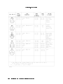
Safety Symbols
The following safety symbols are used throughout this manual. Familiarize yourself with each
of the symbols and its meaning before operating this instrument.
Caution
Warning
The caution sign denotes a hazard. It calls attention to a procedure which,
if not correctly performed or adhered to, could result in damage to or
destruction of the instrument. Do not proceed beyond a caution sign until the
indicated conditions are fully understood and met.
The
warning
sign denotes a hazard. It calls attention to a procedure which,
if not correctly performed or adhered to, could result in injury or loss of life.
Do not proceed beyond a
understood and met.
warning
sign until the indicated conditions are fully
General Safety Considerations
Warning
Before this instrument is switched on
, make sure it has been properly grounded
through the protective conductor of the ac power cable to a socket outlet
provided with protective earth contact.
Any interruption of the protective (grounding) conductor, inside or outside
the instrument, or disconnection of the protective earth terminal can result in
personal injury.
Warning
There are many points in the instrument which can, if contacted, cause personal
injury. Be extremely careful.
Any adjustments or service procedures that require operation of the instrument
with protective covers removed should be performed only by trained service
personnel.
Caution
Before this instrument is switched on, make sure its primary power circuitry
has been adapted to the voltage of the ac power source.
Failure to set the ac power input to the correct voltage could cause damage to
the instrument when the ac power cable is plugged in.
v
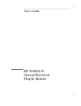
Installation and Verification of the Microwave Transition Analyzer
HP 71500A Microwave Transition Analyzer System
The HP 71500A microwave transition analyzer system is a precongured system that includes
an HP 70820A microwave transition analyzer module, an HP 70004A color display/mainframe,
and a microwave transition analyzer keypad. An external power pack is also shipped with the
HP 71500A system and may be installed if desired. Installation instructions for the external
power pack are provided in Chapter 1.
vi
HP 70820A Microwave Transition Analyzer Module
The HP 70820A microwave transition analyzer module is a 4/8-width module that must be
installed into either an HP 70004A color display/mainframe or an HP 70001A mainframe. A
microwave transition analyzer keypad is also shipped with the HP 70820A module. If you
are using an HP 70004A color display/mainframe with the HP 70820A module, this keypad
may be installed. Installation instructions for the microwave transition analyzer keypad are
provided in Chapter 1. If you are using a black and white display (or no display at all),
certain features (such as color) will not be available.
vii
Operation Verication Tests
The operation verication tests are designed to give you an 80 percent condence level
that the microwave transition analyzer is operating correctly and meeting its specications.
Twenty one automated tests make up the operation verication tests. The operation
verication test disks are shipped with the microwave transition analyzer. You will need
a computer system and test equipment to perform the operation verication tests on the
microwave transition analyzer.
viii
Caution
The RF INPUT circuits can be damaged by electrostatic discharge
(ESD). Therefore, avoid applying static discharges to the front-panel RF
INPUT connectors. Before connecting any coaxial cable to the connectors,
momentarily short the center and outer conductors of the cable together.
Avoid touching the front-panel RF INPUT connectors without rst touching
the frame of the instrument.
Be sure that the microwave transition analyzer is properly earth-grounded to
prevent buildup of static charge.
In This Book
This book helps you install and verify the operation of the microwave transition analyzer. It
provides step-by-step instructions of the installation and verication processes.
Chapter 1
describes the HP 71500A microwave transition analyzer system, the HP
70820A microwave transition analyzer module, and the steps required to
install both of these products. Several optional procedures for the microwave
transition analyzers are also described in this chapter.
will help solve problems that may be encountered during the microwave
Chapter 2
transition analyzer's installation. A variety of problems that could be
encountered during installation are identied. Each of these problems has a
list of possible solutions to help correct the problem.
describes the steps involved in running the Operation Verication software.
Chapter 3
There are several steps required to get the Operation Verication tests
running and several optional steps that will help to customize the software to
your computer system.
contains information regarding the microwave transition analyzer's options
Chapter 4
and accessories, safety information, operation verication software details, and
specic information regarding the operation verication tests.
Note
In this manual, normal front-panel keys are indicated in 4boxed5 letters.
Softkeys are indicated by a shadow typeface.
NNNNNNNNNNNNNNNNNNNN
ix
Contents
1. Installation
Chapter Contents . . . . . . . . . . . . . . . . . . . . . . . . . . .
Installation at a Glance . . . . . . . . . . . . . . . . . . . . . . . .
Installation at a Glance . . . . . . . . . . . . . . . . . . . . . . .
Tools Needed . . . . . . . . . . . . . . . . . . . . . . . . . . .
Installation Overview . . . . . . . . . . . . . . . . . . . . . . .
Installing the HP 71500A Microwave Transition Analyzer System . . . . . .
Conguring an RF Source to the Microwave Transition Analyzer . . . . . .
Step 1. Set Up the Frequency Reference . . . . . . . . . . . . . . . .
Step 2. Select the RF Source . . . . . . . . . . . . . . . . . . . . .
Step 3. Set Up the Instrument Bus . . . . . . . . . . . . . . . . . .
Step 4. Specify the HP-IB Parameters . . . . . . . . . . . . . . . . .
Step 5. Specify the HP-MSIB Parameters . . . . . . . . . . . . . . .
Installing the HP 70820A Microwave Transition Analyzer Module . . . . . .
Step 1. Prepare to Install the HP 70820A Microwave Transition Analyzer
Module . . . . . . . . . . . . . . . . . . . . . . . . . . . . .
Step 2. Check the Address of the HP 70820A Microwave Transition Analyzer
Module . . . . . . . . . . . . . . . . . . . . . . . . . . . . .
Step 3. Check the System's HP-MSIB Addresses . . . . . . . . . . . .
Step 4. Install the HP 70820A Microwave Transition Analyzer Module into
the HP 70001A Mainframe or the HP 70004A Display . . . . . . . .
Optional: Changing the HP-MSIB Address of the HP 70820A Microwave
Transition Analyzer Module . . . . . . . . . . . . . . . . . . . . .
Optional: Installing the Microwave Transition Analyzer's Keypad into the HP
70004A Display . . . . . . . . . . . . . . . . . . . . . . . . . .
Optional: Installing the External Power Pack . . . . . . . . . . . . . . .
Optional: Mounting the System in a Rack . . . . . . . . . . . . . . . .
Optional: Connecting the Microwave Transition Analyzer System to Another
Display or Mainframe . . . . . . . . . . . . . . . . . . . . . . .
Optional: Displaying the Time and the Date . . . . . . . . . . . . . . .
Optional: Changing the Time and the Date . . . . . . . . . . . . . . .
2. If You Have a Problem During Installation
Chapter Contents . . . . . . . . . . . . . . . . . . . . . . . . . . .
Installation Problems . . . . . . . . . . . . . . . . . . . . . . . . .
Problems Requiring Additional Technical Resources . . . . . . . . . . . .
If the Microwave Transition Analyzer Appears to Be Dead . . . . . . . . .
If the Front-Panel LEDs Do Not Light When the Microwave Transition Analyzer
Is Turned On . . . . . . . . . . . . . . . . . . . . . . . . . . .
If the Microwave Transition Analyzer Front-Panel ERR LED Remains Lit or
Blinks After the Self-Test . . . . . . . . . . . . . . . . . . . . . .
1-1
1-2
1-3
1-3
1-3
1-4
1-6
1-6
1-7
1-8
1-9
1-10
1-12
1-12
1-13
1-14
1-16
1-18
1-19
1-20
1-22
1-24
1-25
1-26
2-1
2-2
2-2
2-3
2-4
2-5
Contents-1
If the Microwave Transition Analyzer Front-Panel HP-IB LEDs Remain Lit
After the Self-Test . . . . . . . . . . . . . . . . . . . . . . . .
If Errors Are Reported on the Display . . . . . . . . . . . . . . . . .
If the HP 70004A Display \HP-MSIB" or the HP 70001A Mainframe \I/O
CHECK" Indicator Light Remains Lit . . . . . . . . . . . . . . .
If the HP 70001A Mainframe CURRENT Indicator Light Remains Lit . . .
If the RF Source Does Not Go to Remote . . . . . . . . . . . . . . .
If the Microwave Transition Analyzer's OVEN COLD Indicator Flashes . .
If the Microwave Transition Analyzer Needs to be Returned for Service . .
3. Operation Verication Testing
Chapter Contents . . . . . . . . . . . . . . . . . . . . .
Introduction . . . . . . . . . . . . . . . . . . . . . . .
Step 1. Set Up the Hardware for Operation Verication Testing
Step 2. Prepare the Computer . . . . . . . . . . . . . . .
Step 3. Install the Operation Verication Software Menus . . .
Step 4. Enter the Power Sensor Information . . . . . . . . .
Step 5. Decide Whether to Start Testing . . . . . . . . . . .
Step 6. Start the Operation Verication Testing . . . . . . .
Optional: To Edit the Mass Storage Menu . . . . . . . . . .
Optional: To Edit the Parameter Menu . . . . . . . . . . .
Optional: To Edit the Equipment Menu . . . . . . . . . . .
Optional: To Edit the Power Sensor's Calibration Data . . . .
4. Installation and Operation Verication Reference
Chapter Contents . . . . . . . . . . . . . . . . .
Introduction . . . . . . . . . . . . . . . . . . .
Microwave Transition Analyzer Options . . . . . . .
Microwave Transition Analyzer Accessories . . . . . .
Convenience Kits . . . . . . . . . . . . . . . .
Coaxial Fixed Attenuators . . . . . . . . . . . .
Adapters . . . . . . . . . . . . . . . . . . . .
Coaxial Shorts and Opens . . . . . . . . . . . .
dc Blocking Capacitors . . . . . . . . . . . . .
Bias Networks . . . . . . . . . . . . . . . . .
Phase-Stable Cables . . . . . . . . . . . . . . .
HP-MSIB Cables . . . . . . . . . . . . . . . .
Tools . . . . . . . . . . . . . . . . . . . . .
Miscellaneous Parts and Supplies . . . . . . . . .
System Power Cables . . . . . . . . . . . . . . .
Serial Number Labels . . . . . . . . . . . . . . .
Electrostatic Discharge Information . . . . . . . . .
Reducing ESD Damage . . . . . . . . . . . . .
PC Board Assemblies and Electronic Components .
Test Equipment . . . . . . . . . . . . . . . .
Static-Safe Accessories . . . . . . . . . . . . . .
Computer Compatibility . . . . . . . . . . . . . .
Computer Language Compatibility . . . . . . . .
Printer Compatibility . . . . . . . . . . . . . .
Alternate Key Labels . . . . . . . . . . . . . .
Operation Verication Software Overview . . . . . .
Contents-2
.
.
.
.
.
.
.
.
.
.
.
.
.
.
.
.
.
.
.
.
.
.
.
.
.
.
.
.
.
.
.
.
.
.
.
.
.
.
.
.
.
.
.
.
.
.
.
.
.
.
.
.
.
.
.
.
.
.
.
.
.
.
.
.
.
.
.
.
.
.
.
.
.
.
.
.
.
.
.
.
.
.
.
.
.
.
.
.
.
.
.
.
.
.
.
.
.
.
.
.
.
.
.
.
.
.
2-6
2-7
.
.
.
.
.
2-8
2-9
2-10
2-12
2-13
.
.
.
.
.
.
.
.
.
.
.
.
.
.
.
.
.
.
.
.
.
.
.
.
.
.
.
.
.
.
.
.
.
.
.
.
.
.
.
.
.
.
.
.
.
.
.
.
.
.
.
.
.
.
.
.
.
.
.
.
.
.
.
.
.
.
.
.
.
.
.
.
3-1
3-2
3-3
3-4
3-5
3-6
3-8
3-10
3-11
3-12
3-13
3-14
.
.
.
.
.
.
.
.
.
.
.
.
.
.
.
.
.
.
.
.
.
.
.
.
.
.
.
.
.
.
.
.
.
.
.
.
.
.
.
.
.
.
.
.
.
.
.
.
.
.
.
.
.
.
.
.
.
.
.
.
.
.
.
.
.
.
.
.
.
.
.
.
.
.
.
.
.
.
.
.
.
.
.
.
.
.
.
.
.
.
.
.
.
.
.
.
.
.
.
.
.
.
.
.
.
.
.
.
.
.
.
.
.
.
.
.
.
.
.
.
.
.
.
.
.
.
.
.
.
.
.
.
.
.
.
.
.
.
.
.
.
.
.
.
.
.
.
.
.
.
.
.
.
.
.
.
4-1
4-3
4-4
4-6
4-6
4-7
4-7
4-7
4-8
4-8
4-8
4-9
4-9
4-9
4-9
4-11
4-12
4-12
4-12
4-13
4-14
4-15
4-15
4-16
4-16
4-17
Error Messages or Warnings Dened .
Single Tests Dened . . . . . . . . .
Printed Test Results . . . . . . . . .
Operation Verication Software Menus .
Menu Structure . . . . . . . . . . .
Edit and Command Screen Menus . .
Edit Screen Menus . . . . . . . .
Command Screen Menus . . . . . .
Cursor Keys and Menu Selections . .
Main Menu . . . . . . . . . . . .
Main Menu Softkeys . . . . . . . .
Mass Storage Menu . . . . . . . . .
Mass Storage Menu Edit Screen . .
Mass Storage Menu Command Screen
Parameter Menu . . . . . . . . . .
Parameter Menu Edit Screen . . . .
Parameter Menu Command Screen .
Equipment Menu . . . . . . . . . .
Equipment Menu Edit Screen . . . .
Equipment Menu Command Screen .
Edit Calibration Data . . . . . . . .
Test Menu . . . . . . . . . . . . .
Test Menu Command Screen . . . .
Menu Softkey Diagrams . . . . . . . .
Error and Status Messages . . . . . . .
Recommended Test Equipment . . . . .
Operation Verication Test Descriptions .
Pulse Generator (MOD OUTPUT) . . .
Equipment . . . . . . . . . . . . .
Equipment Setup . . . . . . . . . .
Description . . . . . . . . . . . . .
In Case of Failure . . . . . . . . . .
DAC Output . . . . . . . . . . . . .
Equipment . . . . . . . . . . . . .
Equipment Setup . . . . . . . . . .
Description . . . . . . . . . . . . .
In Case of Failure . . . . . . . . . .
Time Scale Accuracy . . . . . . . . .
Equipment . . . . . . . . . . . . .
Equipment Setup . . . . . . . . . .
Description . . . . . . . . . . . . .
In Case of Failure . . . . . . . . . .
Relative Noise Level (CW) . . . . . . .
Equipment . . . . . . . . . . . . .
Equipment Setup . . . . . . . . . .
Description . . . . . . . . . . . . .
In Case of Failure . . . . . . . . . .
Relative Noise Level (Pulse) . . . . . .
Equipment . . . . . . . . . . . . .
Equipment Setup . . . . . . . . . .
Description . . . . . . . . . . . . .
.
.
.
.
.
.
.
.
.
.
.
.
.
.
.
.
.
.
.
.
.
.
.
.
.
.
.
.
.
.
.
.
.
.
.
.
.
.
.
.
.
.
.
.
.
.
.
.
.
.
.
.
.
.
.
.
.
.
.
.
.
.
.
.
.
.
.
.
.
.
.
.
.
.
.
.
.
.
.
.
.
.
.
.
.
.
.
.
.
.
.
.
.
.
.
.
.
.
.
.
.
.
.
.
.
.
.
.
.
.
.
.
.
.
.
.
.
.
.
.
.
.
.
.
.
.
.
.
.
.
.
.
.
.
.
.
.
.
.
.
.
.
.
.
.
.
.
.
.
.
.
.
.
.
.
.
.
.
.
.
.
.
.
.
.
.
.
.
.
.
.
.
.
.
.
.
.
.
.
.
.
.
.
.
.
.
.
.
.
.
.
.
.
.
.
.
.
.
.
.
.
.
.
.
.
.
.
.
.
.
.
.
.
.
.
.
.
.
.
.
.
.
.
.
.
.
.
.
.
.
.
.
.
.
.
.
.
.
.
.
.
.
.
.
.
.
.
.
.
.
.
.
.
.
.
.
.
.
.
.
.
.
.
.
.
.
.
.
.
.
.
.
.
.
.
.
.
.
.
.
.
.
.
.
.
.
.
.
.
.
.
.
.
.
.
.
.
.
.
.
.
.
.
.
.
.
.
.
.
.
.
.
.
.
.
.
.
.
.
.
.
.
.
.
.
.
.
.
.
.
.
.
.
.
.
.
.
.
.
.
.
.
.
.
.
.
.
.
.
.
.
.
.
.
.
.
.
.
.
.
.
.
.
.
.
.
.
.
.
.
.
.
.
.
.
.
.
.
.
.
.
.
.
.
.
.
.
.
.
.
.
.
.
.
.
.
.
.
.
.
.
.
.
.
.
.
.
.
.
.
.
.
.
.
.
.
.
.
.
.
.
.
.
.
.
.
.
.
.
.
.
.
.
.
.
.
.
.
.
.
.
.
.
.
.
.
.
.
.
.
.
.
.
.
.
.
.
.
.
.
.
.
.
.
.
.
.
.
.
.
.
.
.
.
.
.
.
.
.
.
.
.
.
.
.
.
.
.
.
.
.
.
.
.
.
.
.
.
.
.
.
.
.
.
.
.
.
.
.
.
.
.
.
.
.
.
.
.
.
.
.
.
.
.
.
.
.
.
.
.
.
.
.
.
.
.
.
.
.
.
.
.
.
.
.
.
.
.
.
.
.
.
.
.
.
.
.
.
.
.
.
.
.
.
.
.
.
.
.
.
.
.
.
.
.
.
.
.
.
.
.
.
.
.
.
.
.
.
.
.
.
.
.
.
.
.
.
.
.
.
.
.
.
.
.
.
.
.
.
.
.
.
.
.
.
.
.
.
.
.
.
.
.
.
.
.
.
.
.
.
.
.
.
.
.
.
.
.
.
.
.
.
.
.
.
.
.
.
.
.
.
.
.
.
.
.
.
.
.
.
.
.
.
.
.
.
.
.
.
.
.
.
.
.
.
.
.
.
.
.
.
.
.
.
.
.
.
.
.
.
.
.
.
.
.
.
.
.
.
.
.
.
.
.
.
.
.
.
.
.
.
.
.
.
.
.
.
.
.
.
.
.
.
.
.
.
.
.
.
.
.
.
.
.
.
.
.
.
.
.
.
.
.
.
.
.
.
.
.
.
.
.
.
.
.
.
.
.
.
.
.
.
.
.
.
.
.
.
.
.
.
.
.
.
.
.
.
.
.
.
.
.
.
.
.
.
.
.
.
.
.
.
.
.
.
.
.
.
.
.
.
.
.
.
.
.
.
.
.
.
.
.
.
.
.
.
4-17
4-17
4-17
4-18
4-18
4-19
4-19
4-19
4-20
4-21
4-21
4-22
4-22
4-23
4-24
4-24
4-25
4-26
4-26
4-27
4-28
4-29
4-29
4-31
4-35
4-42
4-45
4-46
4-46
4-46
4-46
4-46
4-47
4-47
4-47
4-47
4-47
4-48
4-48
4-48
4-48
4-48
4-49
4-49
4-49
4-49
4-50
4-51
4-51
4-51
4-51
Contents-3
In Case of Failure . . . . . .
External Trigger (SYNC INPUT)
Equipment . . . . . . . . .
Equipment Setup . . . . . .
Description . . . . . . . . .
In Case of Failure . . . . . .
External 10 MHz Reference . .
Equipment . . . . . . . . .
Equipment Setup . . . . . .
Description . . . . . . . . .
In Case of Failure . . . . . .
Trigger Level . . . . . . . . .
Equipment . . . . . . . . .
Equipment Setup . . . . . .
Description . . . . . . . . .
In Case of Failure . . . . . .
DC Accuracy . . . . . . . . .
Equipment . . . . . . . . .
Equipment Setup . . . . . .
Description . . . . . . . . .
In Case of Failure . . . . . .
IF Step and Impulse Response .
Equipment . . . . . . . . .
Equipment Setup . . . . . .
Description . . . . . . . . .
In Case of Failure . . . . . .
Harmonic Distortion (10 MHz)
Equipment . . . . . . . . .
Equipment Setup . . . . . .
Description . . . . . . . . .
In Case of Failure . . . . . .
Harmonic Distortion ( 10 MHz)
Equipment . . . . . . . . .
Equipment Setup . . . . . .
Description . . . . . . . . .
In Case of Failure . . . . . .
Edge Triggered Sensitivity . . .
Equipment . . . . . . . . .
Equipment Setup . . . . . .
Description . . . . . . . . .
In Case of Failure . . . . . .
RF Response . . . . . . . . .
Equipment . . . . . . . . .
Equipment Setup . . . . . .
Description . . . . . . . . .
In Case of Failure . . . . . .
RF Compression . . . . . . .
Equipment . . . . . . . . .
Equipment Setup . . . . . .
Description . . . . . . . . .
In Case of Failure . . . . . .
>
Contents-4
.
.
.
.
.
.
.
.
.
.
.
.
.
.
.
.
.
.
.
.
.
.
.
.
.
.
.
.
.
.
.
.
.
.
.
.
.
.
.
.
.
.
.
.
.
.
.
.
.
.
.
.
.
.
.
.
.
.
.
.
.
.
.
.
.
.
.
.
.
.
.
.
.
.
.
.
.
.
.
.
.
.
.
.
.
.
.
.
.
.
.
.
.
.
.
.
.
.
.
.
.
.
.
.
.
.
.
.
.
.
.
.
.
.
.
.
.
.
.
.
.
.
.
.
.
.
.
.
.
.
.
.
.
.
.
.
.
.
.
.
.
.
.
.
.
.
.
.
.
.
.
.
.
.
.
.
.
.
.
.
.
.
.
.
.
.
.
.
.
.
.
.
.
.
.
.
.
.
.
.
.
.
.
.
.
.
.
.
.
.
.
.
.
.
.
.
.
.
.
.
.
.
.
.
.
.
.
.
.
.
.
.
.
.
.
.
.
.
.
.
.
.
.
.
.
.
.
.
.
.
.
.
.
.
.
.
.
.
.
.
.
.
.
.
.
.
.
.
.
.
.
.
.
.
.
.
.
.
.
.
.
.
.
.
.
.
.
.
.
.
.
.
.
.
.
.
.
.
.
.
.
.
.
.
.
.
.
.
.
.
.
.
.
.
.
.
.
.
.
.
.
.
.
.
.
.
.
.
.
.
.
.
.
.
.
.
.
.
.
.
.
.
.
.
.
.
.
.
.
.
.
.
.
.
.
.
.
.
.
.
.
.
.
.
.
.
.
.
.
.
.
.
.
.
.
.
.
.
.
.
.
.
.
.
.
.
.
.
.
.
.
.
.
.
.
.
.
.
.
.
.
.
.
.
.
.
.
.
.
.
.
.
.
.
.
.
.
.
.
.
.
.
.
.
.
.
.
.
.
.
.
.
.
.
.
.
.
.
.
.
.
.
.
.
.
.
.
.
.
.
.
.
.
.
.
.
.
.
.
.
.
.
.
.
.
.
.
.
.
.
.
.
.
.
.
.
.
.
.
.
.
.
.
.
.
.
.
.
.
.
.
.
.
.
.
.
.
.
.
.
.
.
.
.
.
.
.
.
.
.
.
.
.
.
.
.
.
.
.
.
.
.
.
.
.
.
.
.
.
.
.
.
.
.
.
.
.
.
.
.
.
.
.
.
.
.
.
.
.
.
.
.
.
.
.
.
.
.
.
.
.
.
.
.
.
.
.
.
.
.
.
.
.
.
.
.
.
.
.
.
.
.
.
.
.
.
.
.
.
.
.
.
.
.
.
.
.
.
.
.
.
.
.
.
.
.
.
.
.
.
.
.
.
.
.
.
.
.
.
.
.
.
.
.
.
.
.
.
.
.
.
.
.
.
.
.
.
.
.
.
.
.
.
.
.
.
.
.
.
.
.
.
.
.
.
.
.
.
.
.
.
.
.
.
.
.
.
.
.
.
.
.
.
.
.
.
.
.
.
.
.
.
.
.
.
.
.
.
.
.
.
.
.
.
.
.
.
.
.
.
.
.
.
.
.
.
.
.
.
.
.
.
.
.
.
.
.
.
.
.
.
.
.
.
.
.
.
.
.
.
.
.
.
.
.
.
.
.
.
.
.
.
.
.
.
.
.
.
.
.
.
.
.
.
.
.
.
.
.
.
.
.
.
.
.
.
.
.
.
.
.
.
.
.
.
.
.
.
.
.
.
.
.
.
.
.
.
.
.
.
.
.
.
.
.
.
.
.
.
.
.
.
.
.
.
.
.
.
.
.
.
.
.
.
.
.
.
.
.
.
.
.
.
.
.
.
.
.
.
.
.
.
.
.
.
.
.
.
.
.
.
.
.
.
.
.
.
.
.
.
.
.
.
.
.
.
.
.
.
.
.
.
.
.
.
.
.
.
.
.
.
.
.
.
.
.
.
.
.
.
.
.
.
.
.
.
.
.
.
.
.
.
.
.
.
.
.
.
.
.
.
.
.
.
.
.
.
.
.
.
.
.
.
.
.
.
.
.
.
.
.
.
.
.
.
.
.
.
.
.
.
.
.
.
.
.
.
.
.
.
.
.
.
.
.
.
.
.
.
.
.
.
.
.
.
.
.
.
.
.
.
.
.
.
.
.
.
.
.
.
.
.
.
.
.
.
.
.
.
.
.
.
.
.
.
.
.
.
.
.
.
.
.
.
.
.
.
.
.
.
.
.
.
.
.
.
.
.
.
.
.
.
.
.
.
.
.
.
.
.
.
.
.
.
.
.
.
.
.
.
.
.
.
.
.
.
.
.
.
.
4-52
4-53
4-53
4-53
4-53
4-53
4-54
4-54
4-54
4-54
4-54
4-55
4-55
4-55
4-55
4-55
4-56
4-56
4-56
4-56
4-56
4-57
4-57
4-57
4-57
4-57
4-58
4-58
4-58
4-58
4-59
4-60
4-60
4-60
4-60
4-60
4-61
4-61
4-61
4-61
4-61
4-62
4-62
4-62
4-62
4-63
4-64
4-64
4-64
4-64
4-65
Amplitude and Phase Ratio . . . . . . . . . . . . .
Equipment . . . . . . . . . . . . . . . . . . . .
Equipment Setup . . . . . . . . . . . . . . . . .
Description . . . . . . . . . . . . . . . . . . . .
In Case of Failure . . . . . . . . . . . . . . . . .
Low Frequency Amplitude and Phase Ratio . . . . . .
Equipment . . . . . . . . . . . . . . . . . . . .
Equipment Setup . . . . . . . . . . . . . . . . .
Description . . . . . . . . . . . . . . . . . . . .
In Case of Failure . . . . . . . . . . . . . . . . .
Sampler Feedthrough . . . . . . . . . . . . . . . .
Equipment . . . . . . . . . . . . . . . . . . . .
Equipment Setup . . . . . . . . . . . . . . . . .
Description . . . . . . . . . . . . . . . . . . . .
In Case of Failure . . . . . . . . . . . . . . . . .
IF Isolation . . . . . . . . . . . . . . . . . . . .
Equipment . . . . . . . . . . . . . . . . . . . .
Equipment Setup . . . . . . . . . . . . . . . . .
Description . . . . . . . . . . . . . . . . . . . .
In Case of Failure . . . . . . . . . . . . . . . . .
Input Crosstalk Isolation . . . . . . . . . . . . . . .
Equipment . . . . . . . . . . . . . . . . . . . .
Equipment Setup . . . . . . . . . . . . . . . . .
Description . . . . . . . . . . . . . . . . . . . .
In Case of Failure . . . . . . . . . . . . . . . . .
Amplitude Accuracy versus Input Power Level . . . . .
Equipment . . . . . . . . . . . . . . . . . . . .
Equipment Setup . . . . . . . . . . . . . . . . .
Description . . . . . . . . . . . . . . . . . . . .
In Case of Failure . . . . . . . . . . . . . . . . .
Alternative to Using a Matched Set of Cables for Testing
60 MHz Low-Pass Filter . . . . . . . . . . . . . . .
110 kHz Low-Pass Filter . . . . . . . . . . . . . . .
.
.
.
.
.
.
.
.
.
.
.
.
.
.
.
.
.
.
.
.
.
.
.
.
.
.
.
.
.
.
.
.
.
.
.
.
.
.
.
.
.
.
.
.
.
.
.
.
.
.
.
.
.
.
.
.
.
.
.
.
.
.
.
.
.
.
.
.
.
.
.
.
.
.
.
.
.
.
.
.
.
.
.
.
.
.
.
.
.
.
.
.
.
.
.
.
.
.
.
.
.
.
.
.
.
.
.
.
.
.
.
.
.
.
.
.
.
.
.
.
.
.
.
.
.
.
.
.
.
.
.
.
.
.
.
.
.
.
.
.
.
.
.
.
.
.
.
.
.
.
.
.
.
.
.
.
.
.
.
.
.
.
.
.
.
.
.
.
.
.
.
.
.
.
.
.
.
.
.
.
.
.
.
.
.
.
.
.
.
.
.
.
.
.
.
.
.
.
.
.
.
.
.
.
.
.
.
.
.
.
.
.
.
.
.
.
.
.
.
.
.
.
.
.
.
.
.
.
.
.
.
.
.
.
.
.
.
.
.
.
.
.
.
.
.
.
.
.
.
.
.
.
.
.
.
.
.
.
.
.
.
.
.
.
.
.
.
.
.
.
.
.
.
.
.
.
.
.
.
.
.
.
.
.
.
.
.
.
.
.
.
.
.
.
.
.
.
4-66
4-66
4-66
4-66
4-66
4-67
4-67
4-67
4-67
4-67
4-68
4-68
4-68
4-68
4-68
4-69
4-69
4-69
4-69
4-70
4-71
4-71
4-71
4-71
4-72
4-73
4-73
4-73
4-73
4-73
4-74
4-75
4-77
Index
Contents-5
Figures
2-1.
2-2.
2-3.
2-4.
4-1.
4-2.
4-3.
4-4.
4-5.
4-6.
4-7.
4-8.
Line Voltage Selector . . . . . . . . . . . . . . . . . . . . . .
Line Fuse Removal and Replacement . . . . . . . . . . . . . . .
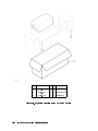
Packaging Materials for the HP 70820A Module . . . . . . . . . .
Packaging Materials for the HP 71500A System . . . . . . . . . . .
Module Serial-Number Label . . . . . . . . . . . . . . . . . . .
Static-Safe Workstation . . . . . . . . . . . . . . . . . . . . .
Main Menu Softkeys . . . . . . . . . . . . . . . . . . . . . . .
Mass Storage Menu and Parameter Menu Softkeys . . . . . . . . .
Equipment Menu Softkeys . . . . . . . . . . . . . . . . . . . .
Test Menu Softkeys . . . . . . . . . . . . . . . . . . . . . . .
60 MHz Low-Pass Filter Schematic Diagram and Component Location .
110 kHz Low-Pass Filter Schematic Diagram and Component Location
.
.
.
.
.
.
.
.
.
.
.
.
.
.
.
.
.
.
.
.
.
.
.
.
2-3
2-3
2-14
2-15
4-11
4-12
4-31
4-32
4-33
4-34
4-75
4-77
.
.
.
.
.
.
.
.
.
.
.
.
2-16
4-10
4-14
4-43
4-76
4-78
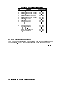
Tables
2-1.
4-1.
4-2.
4-3.
4-4.
4-5.
Hewlett-Packard Sales and Service Oces
Power Cables . . . . . . . . . . . . .
Static-Safe Accessories . . . . . . . . .
Recommended Test Equipment . . . . .
60 MHz Low-Pass Filter Parts List . . .
110 kHz Low-Pass Filter Parts List . . .
Contents-6
.
.
.
.
.
.
.
.
.
.
.
.
.
.
.
.
.
.
.
.
.
.
.
.
.
.
.
.
.
.
.
.
.
.
.
.
.
.
.
.
.
.
.
.
.
.
.
.
.
.
.
.
.
.
.
.
.
.
.
.
.
.
.
.
.
.
.
.
.
.
.
.
.
.
.
.
.
.
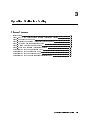
1
Installation
Chapter Contents
Installation at a Glance
Installing the HP 71500A Microwave Transition Analyzer System
Conguring an RF Source to the Microwave Transition Analyzer
Step 1. Set Up the Frequency Reference
Step 2. Select the RF Source
Step 3. Set Up the Instrument Bus
Step 4. Specify the HP-IB Parameters
Step 5. Specify the HP-MSIB Parameters
Installing the HP 70820A Microwave Transition Analyzer Module
Step 1. Prepare to Install the HP 70820A
Microwave Transition Analyzer Module
Step 2. Check the Address of the HP 70820A
Microwave Transition Analyzer Module
Step 3. Check the System's HP-MSIB Addresses
Step 4. Install the HP 70820A Microwave Transition Analyzer Module
into the HP 70001A Mainframe or the HP 70004A Display
Optional: Changing the HP-MSIB Address of the HP 70820A
Microwave Transition Analyzer Module
Optional: Installing the Microwave Transition Analyzer's Keypad
into the HP 70004A Display
Optional: Installing the External Power Pack
Optional: Mounting the System in a Rack
Optional: Connecting the Microwave Transition Analyzer System
to Another Display or Mainframe
Optional: Displaying the Time and the Date
Optional: Changing the Time and the Date
1-2
1-4
1-6
1-6
1-7
1-8
1-9
1-10
1-12
::::::::::::::::::::::::::::::::::::::::::::::::::::::::
:::::::::::::::
:::::::::::::::
:::::::::::::::::::::::::::::::::::::
::::::::::::::::::::::::::::::::::::::::::::::::
::::::::::::::::::::::::::::::::::::::::::
:::::::::::::::::::::::::::::::::::::::
::::::::::::::::::::::::::::::::::
:::::::::::::
:::::::::::::::::::::::::::::::::::
:::::::::::::::::::::::::::::::::::
:::::::::::::::::::::::::::
1-12
1-13
1-14
::::::::::::::::
1-16
::::::::::::::::::::::::::::::::::::
1-18
::::::::::::::::::::::::::::::::::::::::::::::::
:::::::::::::::::::::::::::::::::
::::::::::::::::::::::::::::::::::::
:::::::::::::::::::::::::::::::::::::::::::
::::::::::::::::::::::::::::::::::
:::::::::::::::::::::::::::::::::::
1-19
1-20
1-22
1-24
1-25
1-26
Installation
1-1
Installation at a Glance
1-2
Installation
Installation at a Glance
The microwave transition analyzer is available as part of a precongured system or as a
separate module that you can add to an existing system. The precongured system, the
HP 71500A microwave transition analyzer system includes the HP 70820A microwave
transition analyzer module installed in the HP 70004A Display. The HP 70820A microwave
transition analyzer module may be installed in an existing HP 70004A Display or it may be
installed in an HP 70001A Mainframe using another display or no display at all. Both models
include a custom microwave transition analyzer keypad for use with the HP 70004A Display.
Tools Needed
No tools are required for the basic installation of the HP 71500A system. However, the
HP 70820A module installation and the optional installation steps require these tools:
An 8 mm hex ball driver for installing and removing modules.
A nonconductive stylus, such as a toothpick or similar object, for setting address switches.
A small Pozidriv screwdriver for installing the optional interlock kit.
A large Pozidriv screwdriver for installing the optional external power pack and for
mounting the microwave transition analyzer system into an equipment rack.
A small at-blade screwdriver for installing the microwave transition analyzer keypad in an
HP 70004A display.
Installation Overview
The HP 71500A microwave transition analyzer system installation is straightforward. The
system is preassembled at the factory and installation requires minimal time to complete.
Optional installation steps, such as installing an external power pack, rack mounting the
system, connecting the system to another display or mainframe, and setting the date and
time are also included and may be used as desired. After installation, an RF source may be
congured to the HP 71500A system.
The HP 70820A microwave transition analyzer module installation is more involved. The
HP 70820A module installation procedures include several required and several optional steps.
The required installation steps include:
Preparing to install the HP 70820A module.
Checking the HP-MSIB address of the HP 70820A module.
Checking the system's HP-MSIB addresses.
Installing the HP 70820A module into a display or a mainframe.
Conguring an RF source to the microwave transition analyzer.
The optional installation steps for the HP 70820A module include:
Changing the HP-MSIB address of the HP 70820A module.
Installing the microwave transition analyzer's keypad into the HP 70004A display.
Installing the external power pack.
Rack mounting the microwave transition analyzer system.
Connecting the microwave transition analyzer system to another display or mainframe.
Displaying and changing the time and date.
Installation
1-3
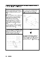
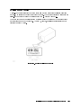
Installing the HP 71500A Microwave Transition Analyzer System
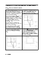
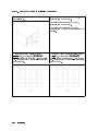
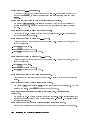
Unpack the HP 71500A microwave transition 2 Set the line-voltage selector to the voltage
analyzer system from its shipping containers.
corresponding to the power source used. The
Inspect the HP 71500A thoroughly to ensure that line-voltage selector is located on the left side of
it was not damaged during shipment.
the microwave transition analyzer, near the front.
1
Caution
Before turning this instrument on, make sure the
line-voltage selector is set to the voltage of the ac
power source:
115 V position for 90 to 132 Vac line input
voltages at 50, 60, or 400 Hz
230 V position for 198 to 264 Vac line input
voltages at 50 or 60 Hz
1-4
Installation
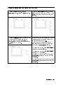
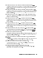
Connect the ac power cord to the rear of the
microwave transition analyzer system. Then
connect the other end of the ac power cord to the
line voltage.
3
4
Press the microwave transition analyzer's
front-panel LINE switch to turn the system on.
5
Press the 4DISPLAY5 key. Press the
NEXT INSTR softkey.
If you want instructions for installing an external
power pack, mounting the system in a rack,
connecting the system to another display or
mainframe, displaying the date and the time, or
changing the date and the time, refer to the
following optional installation steps:
\Optional: Installing the External Power Pack"
on page 1-20
\Optional: Mounting the System in a Rack" on
page 1-22
\Optional: Connecting the Microwave
Transition Analyzer System to Another Display
or Mainframe" on page 1-24
\Optional: Displaying the Time and the Date"
on page 1-25
\Optional: Changing the Time and the Date"
on page 1-26
If you want to congure an RF source to your
microwave transition analyzer, refer to
\Conguring an RF Source to the Microwave
Transition Analyzer" on page 1-6.
An RF source should be congured to your
microwave transition analyzer to get the most
from your microwave transition analyzer.
Without conguring the RF source to the
microwave transition analyzer, your
measurements will be limited.
If you are ready to start making measurements,
refer to the HP 71500A/HP 70820A Microwave
Transition Analyzer Quick Start Guide to get
started.
NNNNNNNNNNNNNNNNNNNNNNNNNNNNN
Installation
1-5
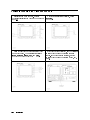
Configuring an RF Source to the Microwave Transition Analyzer
Step 1. Set Up the Frequency Reference
The microwave transition analyzer and RF source
should use the same frequency standard. The
microwave transition analyzer can be congured
so that either the RF source's 10 MHz reference or
the HP 70820A module's 10 MHz reference may
be used as the frequency standard.
The HP 70820A module's 10 MHz reference is not
kept warm when the microwave transition
analyzer's power is turned o unless an external
power pack is installed. The HP 70820A module's
10 MHz reference requires a minimum of
20 minutes to warm-up when the module is
powered up.
If you want to use the RF source's 10 MHz
reference as the frequency standard, perform only
step 1 and step 3 on this page.
If you want to use the HP 70820A module's
10 MHz reference as the frequency standard,
perform only step 2 and step 3 on this page.
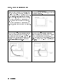
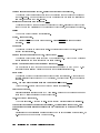
2 Connect the 10 MHz reference cable from the
HP 70820A module's 10 MHz REFERENCE
OUTPUT to the RF source's 10 MHz reference
input.
1-6
Installation
Connect the 10 MHz reference cable from the
RF source's 10 MHz reference output to the
HP 70820A module's 10 MHz REFERENCE
INPUT. Continue at step 3 on this page.
1
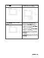
Press the 4MENU5 key. Then press the Config
softkey. Press the 10 MHz INT|EXT softkey until
EXT is underlined if you are using the RF
source's 10 MHz reference as the frequency
standard or until INT is underlined if you are
using the HP 70820A module's 10 MHz reference
as the frequency standard.
3
NNNNNNNNNNNNNNNNNN
NNNNNNNNNNNNNNNNNNNNNNNNNNNNNNNNNNNNNNNN
Step 2. Select the RF Source
1
Press the RF
NNNNNNNNNNNNNNNNNNNNNNNNNN
source
softkey.
Several model numbers of RF sources will be
displayed on the display. Press the softkey
adjacent to the model number of the RF source
that is going to be used.
3
Press the RF src: softkey. RF src: will be
followed by the model number of the current RF
source or the word none if an RF source has not
been selected.
2
NNNNNNNNNNNNNNNNNNNNN
The model number of the selected RF source will
start to ash beneath RF src:. It will continue to
ash until the RF source is properly congured to
the microwave transition analyzer.
Installation
1-7
Step 3. Set Up the Instrument Bus
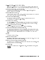
The microwave transition analyzer must use an 1 Press the HP-IB HP-MSIB softkey until the
instrument bus to control the RF source. Either bus that is being used is underlined. The bus that
an HP-IB or an HP-MSIB is used, depending on is underlined is selected.
the type of bus that the RF source is equipped for.
For RF sources that are equipped with both an
HP-IB or an HP-MSIB, either bus may be used.
If you want to control the RF source using the
HP-IB, perform step 1 and step 2 on this page.
If you want to control the RF source using the
HP-MSIB, perform step 1 and step 3 on this page.
NNNNNNNNNNNNNNNNNNNNNNNNNNNNNNNNNNNNNNNN
Connect the HP-IB cable from the rear panel
of the HP 70820A microwave transition analyzer
module to the rear panel of the RF source. (Do
not mistakenly connect the HP-IB cable to HP-IB
connector on the rear panel of the display or the
mainframe.) Continue at \Step 4. Specify the
HP-IB Parameters" on page 1-9.
2
1-8
Installation
Connect the HP-MSIB cables from the rear
panel of the microwave transition analyzer's
display or mainframe to the rear of the RF source
or the RF source's display or mainframe. The
HP-MSIB cables must be routed serially. Continue
at \Step 5. Specify the HP-MSIB Parameters" on
page 1-10.
3
Step 4. Specify the HP-IB Parameters
Determine the HP-IB address of the RF
source. Refer to RF source's documentation for
information regarding its HP-IB address.
1
Press the HP-IB ADDR softkey. Enter the RF
source's two-digit HP-IB address using the
numeric keypad. Press the ENTER softkey.
2
NNNNNNNNNNNNNNNNNNNNNNNNNNNNN
NNNNNNNNNNNNNNNN
Verify that the RF source is properly
4 If you are ready to start making
congured. When the RF source is properly
measurements, refer to the
congured, the microwave transition analyzer will HP 71500A/HP 70820A Microwave Transition
perform an instrument preset on the RF source Analyzer Quick Start Guide to get started.
and the model number of the RF source that
appears beneath RF src: on the display will no
longer ash.
3
Installation
1-9
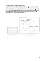
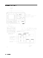
Step 5. Specify the HP-MSIB Parameters
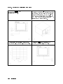
1
Press the 4DISPLAY5 key. Then press the
Address Map softkey.
2
Note the row and the column that the RF
source is listed in. This is its HP-MSIB address.
4
NNNNNNNNNNNNNNNNNNNNNNNNNNNNNNNN
3
1-10
Installation
Turn the display's front-panel knob to locate
the desired RF source in the address map. As the
knob is turned, each item listed on the HP-MSIB
address map is highlighted, one at a time. When
the RF source is highlighted on the address map,
the ACTIVE LED on the front panel of the
corresponding RF source turns on.
Press the 4MENU5 key to return to the
HP 70820A module's HP-MSIB menu.
Press the HP-MSIB ROW softkey. Enter the
6 Press the HP-MSIB COLUMN softkey. Enter the
number of the RF source's HP-MSIB row number number of the RF source's HP-MSIB column
using the numeric keypad. Press the ENTER key. number using the numeric keypad. Press the
ENTER softkey.
5
NNNNNNNNNNNNNNNNNNNNNNNNNNNNNNNN
NNNNNNNNNNNNNNNNNNNNNNNNNNNNNNNNNNNNNNNN
NNNNNNNNNNNNNNNN
NNNNNNNNNNNNNNNN
Verify that the RF source is properly
8 If you are ready to start making
congured. When the RF source is properly
measurements, refer to the
congured, the microwave transition analyzer will HP 71500A/HP 70820A Microwave Transition
perform an instrument preset on the RF source Analyzer Quick Start Guide to get started.
and the model number of the RF source that
appears beneath RF src: on the display will no
longer ash.
7
Installation
1-11
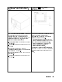
Installing the HP 70820A Microwave Transition Analyzer Module
Step 1. Prepare to Install the HP 70820A Microwave Transition Analyzer Module
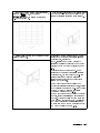
Unpack the HP 70820A microwave transition 2 Inspect the HP 70820A thoroughly to ensure
analyzer module from its shipping containers.
that it was not damaged during shipment.
1
Install the mainframe or the display that you 4 The HP 70820A module is a 4/8-width
will be using with the HP 70820A module. Refer module. It requires four adjacent, empty slots for
to the appropriate installation manual for
installation. Remove previously installed modules
instructions.
from the mainframe or display to open the
necessary slots.
3
1-12
Installation
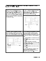
Step 2. Check the Address of the HP 70820A Microwave Transition Analyzer
Module
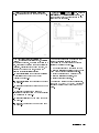
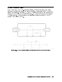
Locate the eight address switches on the top of
the HP 70820A module. These switches are
factory preset to row address 0 and column
address 11.
1
Note
When using the HP 70820A microwave transition
analyzer module with other factory-preset
modules, the factory-preset address of the
HP 70820A does not need to be changed.
Note
Determine the address that the HP 70820A
module is set at.
2
Each element must have a unique 8-bit binary
HP-MSIB address. This address is determined by
the 8 address switches. The three most signicant
bits (MSB) determine the row address. The ve
least signicant bits (LSB) determine the column
address. This manual refers to the decimal
equivalent of the binary address.
Installation
1-13
Step 3. Check the System's HP-MSIB Addresses
Press the LINE switch to turn the mainframe If the display being used is an HP 70004A,
or the display on.
continue at step 2 on this page.
If the display being used is an HP 70205A,
continue at step 3 on this page.
If the display being used is an HP 70206A,
continue at step 4 of this procedure located on the
next page.
1
2 For the HP 70004A Display, press the
4DISPLAY5 key, then press the Address Map
For the HP 70205A Graphics Display, press
the 4DSP5 key, then press the address map
softkey to display the system's HP-MSIB address softkey to display the system's HP-MSIB address
map. Continue at step 5 of this procedure located map. Continue at step 5 of this procedure located
on the next page.
on the next page.
NNNNNNNNNNNNNNNNNNNNNNNNNNNNNNNN
1-14
Installation
3
NNNNNNNNNNNNNNNNNNNNNNNNNNNNNNNN
For the HP 70206A System Graphics Display, 5 Turn the front-panel knob of the display to see
press the 4DISPLAY5 key, then press the
if any other modules are at the address that the
microwave transition analyzer module is set to.
address map softkey to display the system's
HP-MSIB address map.
4
NNNNNNNNNNNNNNNNNNNNNNNNNNNNNNNN
Press the LINE switch of the mainframe or the If there are no other modules at the HP-MSIB
display to turn it o.
address that the microwave transition analyzer
module is set at, continue at
\Step 4. Install the HP 70820A Microwave
Transition Analyzer Module into the HP 70001A
Mainframe or the HP 70004A Display" on page
1-16.
If there is another module at the HP-MSIB
address that the microwave transition analyzer
module is set to, you can change the HP-MSIB
address of either the microwave transition
analyzer module or the other module that is
assigned to that address.
If you want to change the address of the
microwave transition analyzer module, continue
at \Optional: Changing the HP-MSIB Address
of the HP 70820A Microwave Transition
Analyzer Module" on page 1-18.
If you want to change the address of the other
module, refer the installation manual for that
module. After the address of that module has
been changed, continue at \Step 4. Install the
HP 70820A Microwave Transition Analyzer
Module into the HP 70001A Mainframe or the
HP 70004A Display" on page 1-16.
6
Installation
1-15
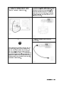
Step 4. Install the HP 70820A Microwave Transition Analyzer Module
into the HP 70001A Mainframe or the HP 70004A Display
Open the front-panel door on the mainframe
or the display.
1
Slide the HP 70820A microwave transition
analyzer module into the mainframe or the display.
2
Press against the HP 70820A module front
4 Close the front-panel door on the mainframe
panel while tightening the hex-nut latch with the or the display.
8 mm hex ball driver (HP part number
8710-1651).
3
1-16
Installation
5
Press the microwave transition analyzer's
front- panel LINE switch to turn the system on.
Press the 4DISPLAY5 or the 4DSP5 key. Press the
NEXT INSTR or the SELECT INSTR softkey. The
key and softkey that you press depends on the
display that you are using.
If you want instructions for installing the
microwave transition analyzer's keypad, installing
an external power pack, mounting the system in a
rack, connecting the system to another display or
mainframe, displaying the date and the time, or
changing the date and the time, refer to the
following optional installation steps:
\Optional: Installing the Microwave Transition
Analyzer's Keypad into the HP 70004A
Display" on page 1-19
\Optional: Installing the External Power Pack"
on page 1-20
\Optional: Mounting the System in a Rack" on
page 1-22
\Optional: Connecting the Microwave
Transition Analyzer System to Another Display
or Mainframe" on page 1-24
\Optional: Displaying the Time and the Date"
on page 1-25
\Optional: Changing the Time and the Date"
on page 1-26
If you want to congure an RF source to your
microwave transition analyzer, refer to
\Conguring an RF Source to the Microwave
Transition Analyzer" on page 1-6.
An RF source should be congured to your
microwave transition analyzer to get the most
from your microwave transition analyzer.
Without conguring the RF source to the
microwave transition analyzer, your
measurements will be limited.
If you are ready to start making measurements,
refer to the HP 71500A/HP 70820A Microwave
Transition Analyzer Quick Start Guide to get
started.
6
NNNNNNNNNNNNNNNNNNNNNNNNNNNNN
NNNNNNNNNNNNNNNNNNNNNNNNNNNNNNNNNNN
Installation
1-17
Optional: Changing the HP-MSIB Address of the
HP 70820A Microwave Transition Analyzer Module
Locate the eight HP-MSIB address switches on
top of the HP 70820A module. These switches are
factory preset to row address 0 and column
address 11.
1
Each element must have a unique 8-bit binary
HP-MSIB address. This address is determined by
the 8 address switches. The three most signicant
bits (MSB) determine the row address. The ve
least signicant bits (LSB) determine the column
address. This manual refers to the decimal
equivalent of the binary address.
Only the modules and the stand-alone instruments
that have addresses in row 0 can communicate
over the HP-IB bus.
Address 0, 31 is an illegal address. No elements
may be set to this address.
A thin, nonconductive stylus, such as a toothpick
or similar object, is useful for setting the address
switches.
Set the address switches of the HP 70820A
Continue at \Step 4. Install the HP 70820A
module to an HP-MSIB address in row 0 that does Microwave Transition Analyzer Module into the
not have a module assigned to it.
HP 70001A Mainframe or the HP 70004A
Display" on page 1-16.
2
1-18
Installation
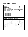
Optional: Installing the Microwave Transition Analyzer's Keypad
into the HP 70004A Display
The microwave transition analyzer's keypad is
designed to give the user front-panel keys that
serve the same function as often-used softkeys.
The use of this keypad will save steps when
making measurements. This keypad may only be
used with the HP 70004A display. However, even
if this keypad is not installed, all of the microwave
transition analyzer's functions are accessible using
the display's softkeys.
1
Install the microwave transition analyzer's
keypad by inserting the left side of the keypad into
the HP 70004A's front panel. Press the right side
of the keypad in until it snaps into the front panel.
If you want instructions for installing an external
power pack, mounting the system in a rack,
connecting the system to another display or
mainframe, or displaying or changing the date and
time, refer to the following optional installation
steps:
\Optional: Installing the External Power Pack"
on page 1-20
\Optional: Mounting the System in a Rack" on
page 1-22
\Optional: Connecting the Microwave
Transition Analyzer System to Another Display
or Mainframe" on page 1-24
\Optional: Displaying the Time and the Date"
on page 1-25
\Optional: Changing the Time and the Date"
on page 1-26
If you want to congure an RF source to your
microwave transition analyzer, refer to
\Conguring an RF Source to the Microwave
Transition Analyzer" on page 1-6.
2
Remove the existing keypad or cover from the
HP 70004A by inserting a at-blade screwdriver
into slot on the keypad or cover. Push the
screwdriver straight in until the spring release the
existing keypad or cover. Do not move the
screwdriver handle toward either side.
Installation
1-19
Optional: Installing the External Power Pack
Unpack the external power pack from its
shipping container. Inspect the external power
pack and its power cable to ensure that they are
not damaged.
1
If you want to install the external power pack to
the rear of the microwave transition analyzer, refer
to step 2 on this page.
If your microwave transition analyzer is rack
mounted and you want to install the external
power pack to the equipment rack, refer to step 3
on this page.
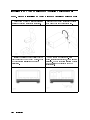
Screw the external power pack onto the rear of 3 The external power pack may also be mounted
the HP 70004A display or the HP 70001A
to an equipment rack as shown below. Order
mainframe. Use the four screws provided.
HP part number 70310-60030 for the external
Continue with step 4 of this procedure located on power pack's rack mount kit.
the next page.
2
1-20
Installation
4 Connect the external power pack cable to
EXT POWER on the rear of the HP 70820A
Microwave Transition Analyzer module.
Warning
Set the two 2-position SELECTION (VOLTS)
switches to the voltage of ac power source. The
external power pack must have its line-voltage
selector set correctly before the power pack is
plugged into the ac power source. An incorrect
line-voltage selection can cause damage to the
external power pack.
5
Plug the external power pack into the ac
power source.
6
Before plugging the external power pack into the
ac power source, verify that the external power
pack and the power cable are not damaged, and
that the power-source socket outlet is provided
with protective earth contact. Any interruption of
the protective (grounding) conductor either on the
inside or the outside of the external power pack,
or disconnection of the protective earth terminal,
can result in personal injury.
Installation
1-21
Optional: Mounting the System in a Rack
Hardware kits are needed to rack mount the
system. Refer to the lists of the hardware kits,
below, for the options, the descriptions, and the
HP part numbers.
Caution
For HP 70004A Display:
rackmount slide kit
(HP part number 5062-7086)
Option 908 rack ange kit without handles
(HP part number 5062-3979)
Option 913 rack ange kit with handles
(HP part number 5062-4073)
Option 810
Do not rack mount multiple displays or
mainframes with one rack-mount hardware kit.
One rack-mount hardware kit must be ordered for
each display or mainframe.
For HP 70001A Mainframe:
rackmount slide kit
(HP part number 5062-0781)
Option 908 rack ange kit without handles
(HP part number 5062-3978)
Option 913 rack ange kit with handles
(HP part number 5062-4072)
Option 810
Slide the plastic trim strip on each handle
forward and remove them. Remove the screws
securing each handle to the instrument.
1
1-22
Installation
Remove the feet from the bottom of the
display or mainframe.
2
Caution
Install the rack-mount hardware kit on the
display or mainframe. The installation
instructions are included with each kit.
3
Be sure to use the correct hardware when
replacing parts. Both metric and English hardware
are used with these instruments. Using incorrect
screw sizes may damage the instrument cabinet.
Slide the display or mainframe into the rack.
Insert two screws through the holes in the rack
ange on each side of the instrument and into the
front of the rack. Tighten each screw.
4
If the system needs to be connected to another
display or mainframe, refer to \Optional:
Connecting the Microwave Transition Analyzer
System to Another Display or Mainframe" on
page 1-24.
If you want to congure an RF source to your
microwave transition analyzer, refer to
\Conguring an RF Source to the Microwave
Transition Analyzer" on page 1-6.
Installation
1-23
Optional: Connecting the Microwave Transition Analyzer System
to Another Display or Mainframe
The microwave transition analyzer system may be 1 Assemble the microwave transition analyzer
connected to another display or mainframe. The system to the HP 70001A Mainframe as shown
microwave transition analyzer system may be left below. Order interlock kit (HP part number
separate or physically congured in one of two
5061-9061) for hardware and instructions.
ways.
Rack mounted
Stacked and interlocked (with a mainframe only)
If you want to leave the microwave transition
analyzer system and the display or mainframe
separate, refer only to step 2 below.
If you want to rack mount the microwave
transition analyzer system and the display or
mainframe, refer to \Optional: Mounting the
System in a Rack" on page 1-22 and to step 2
below.
If you want to stack and interlock the microwave
transition analyzer system with the mainframe,
continue at step 1 on this page.
Connect the HP-MSIB cables serially: coupling
the input of one element to the output of the next
until the loop is completed. The HP-MSIB cable
connections between the HP 71500A and the
HP 70001A Mainframe are shown below.
2
Note
Long HP-MSIB cables between the display and
mainframe allow remote operation. Since the
signals on the HP-MSIB are digital, measurement
speed is only slightly degraded. Measurement
accuracy is not aected by HP-MSIB cable length.
1-24
Installation
Optional: Displaying the Time and the Date
Press the Config softkey. Press the
2 Press the show TIM|DAT softkey. Continue
pressing this softkey until both TIM and DAT are
more 1 of 3 softkey. Press the clock softkey.
underlined and both the time and the date are
displayed.
1
NNNNNNNNNNNNNNNNNN
NNNNNNNNNNNNNNNNNNNNNNNNNNNNNNNN
NNNNNNNNNNNNNNNNNNNNNNNNNNNNNNNNNNN
NNNNNNNNNNNNNNNN
Press the US|EURO softkey to toggle the date
to be displayed in the desired format. For
example, April 18th of 1991 is displayed as
APR 18, 1991 in US format and is displayed as
18.04.1991 in EURO format.
3
NNNNNNNNNNNNNNNNNNNNN
If the time or the date is not current and you want
to correct it, refer to \Optional: Changing the
Time and the Date" on page 1-26.
If the time and the date is current you may
display either the time or the date, or both, or
neither using the show TIM|DAT softkey.
To display only the time, press show TIM|DAT
until only TIM is underlined.
To display only the date, press show TIM|DAT
until only DAT is underlined.
To display both the time and the date, press
show TIM|DAT until both TIM and DAT are
underlined.
To display neither the time nor the date, press
show TIM|DAT until neither TIM nor DAT are
underlined.
NNNNNNNNNNNNNNNNNNNNNNNNNNNNNNNNNNN
NNNNNNNNNNNNNNNNNNNNNNNNNNNNNNNNNNN
NNNNNNNNNNNNNNNNNNNNNNNNNNNNNNNNNNN
NNNNNNNNNNNNNNNNNNNNNNNNNNNNNNNNNNN
NNNNNNNNNNNNNNNNNNNNNNNNNNNNNNNNNNN
Installation
1-25
Optional: Changing the Time and the Date
Display the time and the date. Refer to
\Optional: Displaying the Time and the Date" on
page 1-25.
1
2
With the clock softkeys displayed, press
set clock .
NNNNNNNNNNNNNNNNNNNNNNNNNN
Press the rst time or date units softkey that 4 If the time is being corrected, use the display's
you want to change. The units softkeys include numeric keypad to input the correct hours or
minutes. If the date is being corrected, use the
HOURS , MINUTES , MONTH , DAY , and YEAR .
numeric keypad to input the correct month, day,
or year.
3
NNNNNNNNNNNNNNNN
1-26
NNNNNNNNNNNNNNNNNNNNN
Installation
NNNNNNNNNNNNNNNN
NNNNNNNNNN
NNNNNNNNNNNNN
5
Press 4ENTER5.
Press prev
softkeys.
7
NNNNNNNNNNNNNNNNNNNNNNNNNN
menu
Repeat steps 3, 4, and 5 of this procedure until
the current time and date is displayed.
6
to return to the clock
If the time and the date is current you may
display either the time or the date, or both, or
neither using the show TIM|DAT softkey.
To display only the time, press show TIM|DAT
until only TIM is underlined.
To display only the date, press show TIM|DAT
until only DAT is underlined.
To display both the time and the date, press
show TIM|DAT until both TIM and DAT are
underlined.
To display neither the time nor the date, press
show TIM|DAT until neither TIM nor DAT are
underlined.
NNNNNNNNNNNNNNNNNNNNNNNNNNNNNNNNNNN
NNNNNNNNNNNNNNNNNNNNNNNNNNNNNNNNNNN
NNNNNNNNNNNNNNNNNNNNNNNNNNNNNNNNNNN
NNNNNNNNNNNNNNNNNNNNNNNNNNNNNNNNNNN
NNNNNNNNNNNNNNNNNNNNNNNNNNNNNNNNNNN
Installation
1-27
2
If You Have a Problem During Installation
Chapter Contents
Installation problems
Problems requiring additional technical resources
If the microwave transition analyzer appears to be dead
If the front-panel LEDs do not light when the
microwave transition analyzer is turned on
If the microwave transition analyzer front-panel ERR LED
remains lit or blinks after the self-test
If the microwave transition analyzer front-panel
HP-IB LEDs remain lit after the self-test
If errors are reported on the display
If the HP 70004A Display \HP-MSIB" or the HP 70001A Mainframe
\I/O CHECK" indicator light remains lit
If the HP 70001A Mainframe CURRENT indicator light remains lit
If the RF source does not go to remote
If the microwave transition analyzer's OVEN COLD indicator ashes
If the microwave transition analyzer needs to be returned for service
::::::::::::::::::::::::::::::::::::::::::::::::::::::::::
:::::::::::::::::::::::::::::::
::::::::::::::::::::::::
2-2
2-2
2-3
::::::::::::::::::::::::::::::::::
2-4
:::::::::::::::::::::::::::::::::::::::
2-5
:::::::::::::::::::::::::::::::::::
::::::::::::::::::::::::::::::::::::::::::::
2-6
2-7
2-8
2-9
2-10
2-12
2-13
:::::::::::::::::::::::::::::::::::
::::::::::::
:::::::::::::::::::::::::::::::::::::::
::::::::::
::::::::::
If You Have a Problem During Installation
2-1
Installation Problems
This chapter will help correct problems that may be encountered during the installation of the
microwave transition analyzer. The problem or symptom is listed at the top of each page.
Most problems have a brief description or explanation to provide additional information
regarding the problem. Following the problem and its description, a checklist of items that
could cause the problems during installation is provided. Using the checklist of possible
solutions will help to correct the problem. If the problem is internal to the microwave
transition analyzer, the checklist will also help to identify the faulty module, display or
mainframe.
Problems Requiring Additional Technical Resources
Problems that are internal to a module, a display, or a mainframe will require additional
technical information. Refer to the service documentation for the faulty module, display,
or mainframe or return the instrument to Hewlett-Packard for servicing. Instructions for
returning the instrument to Hewlett-Packard are provided in \If the Microwave Transition
Analyzer Needs to be Returned for Service" on page 2-13.
2-2
If You Have a Problem During Installation
If the Microwave Transition Analyzer Appears to Be Dead
Each time that the microwave transition analyzer is turned on, the following actions take
place:
1. The front-panel STATUS and HP-IB LEDs on the module light.
2. The display's model number is displayed.
3. The system runs through an INITIALIZING routine (power on initialization).
4. The SELF TEST routine runs (the front-panel LEDs turn o, one at a time during the
self-test).
5. The MEASURE LED starts blinking at the end of the self-test.
If these actions do not occur, check the following things:
Check that the microwave transition analyzer is connected to the ac power source.
Check that the line voltage selector switch is set to the correct voltage for the power source.
The line voltage selector switch is located on the left side of the HP 70004A Display, on
the bottom of the HP 70001A Mainframe, or on the rear panel of the HP 70206A System
Graphic Display. See Figure 2-1.
Figure 2-1. Line Voltage Selector
Check the line fuse on the display or the mainframe to ensure that it is not damaged.
The line fuse for this instrument is located inside the power-cord receptacle housing on the
rear of the display and mainframe. Also included in this housing is a spare fuse. The fuse is
a 5 by 20 mm fuse rated at 6.3A, 250 V (HP part number 2110-0703). This line fuse can be
used with both 120 V and 230 V power sources. Refer to Figure 2-2.
Figure 2-2. Line Fuse Removal and Replacement
If You Have a Problem During Installation
2-3
If the Front-Panel LEDs Do Not Light When
the Microwave Transition Analyzer Is Turned On
When the microwave transition analyzer is turned on, the module self-test procedure turns
on the STATUS LEDs, the HP-IB LEDs, the MEASURE LED, and the EXT REF LED on
the front panel of the module. As the self-test continues to run, the STATUS LEDs and the
HP-IB LEDs are turned o in the following sequence. (The STATUS LEDs (ERR and ACT)
are turned on and then turned o so quickly that it may not be apparent that they were
turned on.)
1. ERR
2. ACT
3. SRQ
4. TLK
5. LSN
6. RMT
After the self-test is complete, the following actions will occur:
1. The MEASURE LED will start to blink.
2. The EXT REF LED will remain on if the external reference signal is connected to the 10
MHz REFERENCE INPUT connector on the rear panel of the module. If there is not an
external reference signal connected to the 10 MHz REFERENCE INPUT connector, the
EXT REF LED will turn o.
If the Front-panel LEDs do not light when the microwave transition analyzer is turned on:
Ensure that the display or mainframe is operating properly.
If the display or mainframe is not providing the correct power to the microwave transition
analyzer module, the microwave transition analyzer will not operate correctly. The
microwave transition analyzer module may need to be removed to determine if the display
or mainframe is operating properly. Refer to the display's or mainframe's installation
manual for information regarding proper operation.
If the display or mainframe is operating properly, the microwave transition analyzer
module is probably faulty and additional technical resources are required. Refer to
\Problems Requiring Additional Technical Resources" on page 2-2.
If other instruments are connected to the display or the mainframe via the HP-MSIB, check
that they are turned on.
2-4
If You Have a Problem During Installation
If the Microwave Transition Analyzer Front-Panel ERR LED
Remains Lit or Blinks After the Self-Test
The ERR LED is one of the two STATUS LEDs on the front panel of the microwave
transition analyzer module. The ERR LED should be turned on and then turned o during
the microwave transition analyzer's self-test. It is turned on and turned o so quickly during
the self-test that it may not be able to be observed.
After the self-test, the ERR LED lights when an error (problem) is encountered. When it
lights, it will either remain on continuously or it will blink.
If the ERR LED remains on continuously, it is indicating that there may be a problem with
the microwave transition analyzer. Perform the following steps:
1. Press 4DISPLAY5 and REPORT ERRORS .
2. Check the display for the reported error.
3. Refer to \If Errors Are Reported on the Display" on page 2-7 for help correcting the error.
If the ERR LED blinks, it is indicating that there may be a problem with the HP-MSIB.
Check the following items:
Check that all HP-MSIB cables are securely connected and ensure that they are connected
serially to form a loop.
Check whether there are two modules in the system with the same HP-MSIB address.
NNNNNNNNNNNNNNNNNNNNNNNNNNNNNNNNNNNNNNNNN
If You Have a Problem During Installation
2-5
If the Microwave Transition Analyzer Front-Panel HP-IB LEDs
Remain Lit After the Self-Test
The HP-IB LEDs on the front panel of the microwave transition analyzer are turned on and
then turned o, one at a time, during the microwave transition analyzer's self test. There are
four HP-IB LEDs. They are service request (SRQ), talk (TLK), listen (LSN), and remote
(RMT). The HP-IB LEDs reveal the status of the microwave transition analyzer module when
it is being controlled by a computer.
The table below shows each HP-IB LED, its purpose, and what should be checked if it
remains on after the self-test.
LED
SRQ
TLK
LSN
RMT
2-6
Function
This LED lights when the microwave
transition analyzer has requested
computer service.
This LED lights when a controller has
addressed the microwave transition
analyzer to talk over the HP-IB.
Solution
Check for error messages on the display.
The microwave transition analyzer module is
probably faulty. It will require additional
technical resources. Refer to \Problems Requiring
Additional Technical Resources" on page 2-2.
This LED lights when a controller has The microwave transition analyzer module is
addressed the microwave transition
probably faulty. It will require additional
analyzer to listen over the HP-IB.
technical resources. Refer to \Problems Requiring
Additional Technical Resources" on page 2-2.
This LED lights if the remote enable The microwave transition analyzer module is
(REN) line is asserted and the
probably faulty. It will require additional
microwave transition analyzer is
technical resources. Refer to \Problems Requiring
addressed by a controller. In addition, Additional Technical Resources" on page 2-2.
depending on the instructions received
from the controller, the SRQ, the TLK,
or the LSN LEDs may also light.
If this LED is on, the microwave
transition analyzer won't respond when
the front-panel keys are pressed. The
RMT LED will turn o when the
display's 4LCL5 key is pressed.
If You Have a Problem During Installation
If Errors Are Reported on the Display
Note the error number and the error message.
Refer to the list of common errors below. If the error is not on the list of common errors,
refer to the complete list of errors in the HP 71500A Microwave Transition Analyzer
Reference .
List of Common Errors
Error
6203
6204
6205
6396
6611
Description
no instrument present
This can occur when the RF source is not turned on or when the RF source
is not correctly congured to the microwave transition analyzer. Refer to
\Conguring an RF Source to the Microwave Transition Analyzer" in
Chapter 1.
instrument does not match cong
This can indicate when the RF source is not correctly congured to the
microwave transition analyzer. The selected RF source does not match
the RF source congured to the microwave transition analyzer. Refer to
\Conguring an RF Source to the Microwave Transition Analyzer" in
Chapter 1.
not active controller
This indicates that the HP 70820A is not the active controller. Set the SYS
CNTRL switch to 1. Refer to \Step 2. Check the Address of the HP 70820A
Microwave Transition Analyzer Module" in Chapter 1 for location of the SYS
CNTRL switch.
no ext ref
This indicates that the microwave transition analyzer is set for external
reference when the external reference is not present. Refer to \Step 1. Set Up
the Frequency Reference" in Chapter 1 to connect the external reference.
questionable cal data (ch1)
This indicates that channel 1 needs to be recalibrated. To recalibrate channel
1, press 4MENU5, page 1 of 2 , Calib , i.f. calib , and CAL CH1 . Then
follow the instructions on the display for recalibration.
NNNNNNNNNNNNNNNNNNNNNNNNNNNNNNNNNNN
6612
NNNNNNNNNNNNNNNNNNNNNNNNNNNNNNNN
NNNNNNNNNNNNNNNNNNNNNNN
questionable cal data (ch2)
This indicates that channel 2 needs to be recalibrated. To recalibrate channel
2, press 4MENU5, page 1 of 2 , Calib , i.f. calib , and CAL CH2 . Then
follow the instructions on the display for recalibration.
NNNNNNNNNNNNNNNNNNNNNNNNNNNNNNNNNNN
6385
NNNNNNNNNNNNNNNNN
NNNNNNNNNNNNNNNNN
NNNNNNNNNNNNNNNNNNNNNNNNNNNNNNNN
NNNNNNNNNNNNNNNNNNNNNNN
clock broken or needs setting
This indicates that there is a problem with the real time clock. Try to reset
the clock. Refer to \Optional: Changing the Time and the Date" in Chapter
1 to reset the clock.
If You Have a Problem During Installation
2-7
If the HP 70004A Display \HP-MSIB" or the HP 70001A Mainframe
\I/O CHECK" Indicator Light Remains Lit
The HP 70004A Display HP-MSIB fault indicator light and the HP 70001A Mainframe I/O
CHECK status indicator light indicate the status of the HP-MSIB. If either of the lights are
on, there is a problem with the HP-MSIB.
Verify that the power to all mainframes and stand-alone display instruments is on.
Check that all HP-MSIB cables are securely connected and ensure that they are connected
serially to form a loop.
Check whether there are two modules in the system with the same HP-MSIB address.
Check for a faulty mainframe or stand-alone display by removing all of the HP-MSIB cables
and noting whether the indicator light remains on.
If the indicator light is still on, the mainframe or stand-alone display is probably causing
the HP-MSIB problem.
If the indicator light goes out, the problem is either with the HP-MSIB cables or with the
instrument that the mainframe or display was connected to.
2-8
If You Have a Problem During Installation
If the HP 70001A Mainframe CURRENT Indicator Light Remains Lit
The CURRENT error indicator light turns on when the mainframe power supply senses a
current overload.
Check to see which module is causing the current overloading condition.
Remove one module from the mainframe.
Cycle the power.
If the indicator light is o, the module was faulty.
If the indicator light is still on, continue removing modules, one at a time, until the
module causing the indicator light is identied.
If the indicator light remains on after all modules have been removed, the mainframe is
probably faulty.
If You Have a Problem During Installation
2-9
If the RF Source Does Not Go to Remote
The RF source must be in remote status to be controlled by the microwave transition
analyzer. Most RF sources have an indicator light on the front panel to indicate when they
are in remote status. If necessary, refer to the manual for the RF source being used to
determine the location of the remote status indicator.
Check that both the microwave transition analyzer and the RF source have the power
turned on.
Ensure that the RF source is congured to the microwave transition analyzer.
Press 4MENU5, Config , and RF source . The model number of the selected RF source will
be displayed beneath RF src: in the upper right-hand corner of the display.
If the RF source is congured properly to the microwave transition analyzer, the model
number will not ash.
If the RF source is not congured properly to the microwave transition analyzer, the
model number will ash.
If the RF source is not congured properly to the microwave transition analyzer, check
the next three items. Refer to \Conguring an RF Source to the Microwave Transition
Analyzer" in Chapter 1 for information on performing these checks.
Check that the correct RF source is selected.
If the RF source is HP-IB controlled, check the following items:
Check that the HP-IB cable is connected between the rear panel of the microwave
transition analyzer module and the RF source.
The HP-IB cable must be connected to the HP 70820A module's HP-IB connector,
not the HP-IB connector on the rear of the display or the mainframe.
Check that the microwave transition analyzer has the correct HP-IB address for the
RF source.
If the RF source is HP-MSIB controlled, check the following items:
Check that all HP-MSIB cables are securely connected and ensure that they are
connected serially to form a loop.
Check that the microwave transition analyzer has the correct HP-MSIB address for
the RF source.
NNNNNNNNNNNNNNNNNNNN
2-10
NNNNNNNNNNNNNNNNNNNNNNNNNNNNN
If You Have a Problem During Installation
Check the address of the microwave transition analyzer.
The microwave transition analyzer must be set to an HP-MSIB address in row 0 to
communicate via the HP-IB bus.
Look at the display's address map to ensure that the HP-MSIB address of the microwave
transition analyzer is in row 0. Refer to \Step 3. Check the System's HP-MSIB
Addresses" in Chapter 1 for information about using the address map.
If the HP-MSIB address is not in row 0, refer to \Optional: Changing the HP-MSIB
Address of the HP 70820A Microwave Transition Analyzer Module" in Chapter 1.
If the RF source is in the HP 8360 series (for example, the HP 83640), ensure the RF source
is set for either TMSL, ANALYZER, or SCPI programming language. Refer to the RF
source's documentation for information about changing the programming language.
If You Have a Problem During Installation
2-11
If the Microwave Transition Analyzer's OVEN COLD Indicator
Flashes
When the microwave transition analyzer is turned on, an indicator will ash on the display to
advise that the circuitry for the 10 MHz frequency reference is cold. This OVEN COLD indicator
ashes until the oven warms up to its operating temperature. When the oven is warm, the
OVEN COLD indicator turns o.
If the microwave transition analyzer is using a frequency reference from an external RF
source, the OVEN COLD indicator should not ash. The indicator is disabled when microwave
transition analyzer has an external reference. If the OVEN COLD indicator ashes, make the
following checks:
Check that the reference cable from the RF source is connected to the 10 MHz
REFERENCE INPUT connector on the rear of the microwave transition analyzer
module.
Check that the RF source has a 10 MHz reference signal at its output.
Check that the 10 MHz reference cable between the RF source and the microwave
transition analyzer module is not damaged.
If the microwave transition analyzer has an external power pack installed, the oven is kept
warm even when the microwave transition analyzer is turned o. The OVEN COLD indicator
will only ash momentarily when the microwave transition analyzer is turned on. If the
OVEN COLD indicator ashes, make the following checks:
Check that the external power pack cable is connected to the EXT POWER connector on
the rear of the microwave transition analyzer module.
Check that the external power pack has been connected to the microwave transition
analyzer and turned on long enough to allow it to warm the oven up to its operating
temperature. Allow the external power pack approximately 30 minutes to warm up the
oven when the external power pack is initially connected to the microwave transition
analyzer.
Check that the external power pack is operating properly.
Refer to \Optional: Installing the External Power Pack" in Chapter 1.
Check that the voltage selector switch on the external power pack is set for the correct
ac power source.
Check that the external power pack is connected to the ac power source.
Check that the unloaded output of the external power pack cable is between +35 Vdc
and +40 Vdc.
Check that the line fuse of the external power pack is not damaged.
If the microwave transition analyzer's internal frequency reference is being used without an
external power pack, check the following if the OVEN COLD indicator ashes:
Check to see that the 10 MHz frequency reference warms up after the microwave
transition analyzer is turned on.
Allow approximately 30 minutes for the frequency reference to warm up enough to turn
o the Oven Cold indicator on the display.
2-12
If You Have a Problem During Installation
If the Microwave Transition Analyzer Needs to be
Returned for Service
The original shipping containers and materials, or the equivalent, must be used when
repackaging the display with the module or the module alone. Packaging materials identical to
the original factory packaging (refer to Figure 2-3 on page 2-14 or to Figure 2-4 on page 2-15)
can be purchased through any Hewlett-Packard oce. However, if these shipping materials are
not available, instruments can be repackaged using the information below.
Caution
Instrument damage can result from using packaging materials other than
the original shipping materials or equivalent. Never use styrene pellets as
packaging materials. They do not adequately cushion the instrument or
prevent it from shifting in the carton. They cause instrument damage by
generating static electricity.
Use the following procedure to prepare the instrument for shipment:
1. Fill out a blue repair card (located at the end of this manual) and attach it to the
instrument. Also send copies of any error messages and performance data recorded for the
instrument. If a blue repair card is not available, send the following information with the
returned instrument:
1. Type of service required.
2. Description of the problem; state if the problem is constant or intermittent.
3. Name and phone number of technical contact person.
4. Return address.
5. Model number of returned instrument.
6. Full serial number of returned instrument.
7. List of any accessories returned with instrument.
2. Pack the instrument in the original shipping materials (or the equivalent). However, if
these are not available, instruments can be repackaged for shipment using the following
instructions.
1. Wrap the instrument in antistatic plastic to reduce the possibility of ESD-caused
damage.
2. For instruments that weigh less than 54 kg (120 lb), use a double-walled, corrugated
cardboard carton of 159 kg (350 lb) test strength. The carton must be large enough and
strong enough to accommodate the instrument. Allow at least 3 to 4 inches on all sides
of the instrument for packing material.
3. Surround the equipment with 3 to 4 inches of packing material to protect the instrument
and prevent it from moving in the carton. If packing foam is not available, the best
alternative is S.D.-240 Air Cap TM from Sealed Air Corporation (Commerce, California
90001). Air Cap is a plastic sheet lled with 1-1/4 inch air bubbles. Use the pink
(antistatic) Air Cap to reduce static electricity. Wrap the instrument several times in
this material to protect the instrument and prevent it from moving in the carton.
3. Seal the carton with strong nylon adhesive tape.
4. Mark the carton \FRAGILE, HANDLE WITH CARE."
5. Retain copies of all shipping papers.
If You Have a Problem During Installation
2-13
Item HP Part Number CD Qty
1
2
3
9211-6561
9220-4836
4208-0592
8
5
1
Description
1 Carton
1 Foam Pad Set
1 Spacer Pad
Figure 2-3. Packaging Materials for the HP 70820A Module
2-14
If You Have a Problem During Installation
Item HP Part Number CD Qty
1
2
3
9211-6353
9211-6355
9220-4742
6
8
2
Description
1 Carton-Outer
1 Carton-Inner
1 Foam Pad Set
Figure 2-4. Packaging Materials for the HP 71500A System
If You Have a Problem During Installation
2-15
Table 2-1. Hewlett-Packard Sales and Service Offices
US FIELD OPERATIONS
HEADQUARTERS
Hewlett-Packard Company
19320 Pruneridge Avenue
Cupertino, CA 95014, USA
(800) 752-0900
California
Hewlett-Packard Co.
1421 South Manhattan Ave.
Fullerton, CA 92631
(714) 999-6700
Hewlett-Packard Co.
301 E. Evelyn
Mountain View, CA 94041
(415) 694-2000
EUROPEAN OPERATIONS
HEADQUARTERS
Hewlett-Packard S.A.
150, Route du Nant-d'Avril
1217 Meyrin 2/Geneva
Switzerland
(41 22) 780.8111
INTERCON OPERATIONS
HEADQUARTERS
Hewlett-Packard Company
3495 Deer Creek Rd.
Palo Alto, California 94304-1316
(415) 857-5027
Australia
Hewlett-Packard Australia Ltd.
Hewlett-Packard France
31-41 Joseph Street
1 Avenue Du Canada
Blackburn, Victoria 3130
Zone D'Activite De Courtaboeuf (61 3) 895-2895
F-91947 Les Ulis Cedex
France
Canada
(33 1) 69 82 60 60
Hewlett-Packard (Canada) Ltd.
17500 South Service Road
Germany
Trans-Canada Highway
Kirkland, Quebec H9J 2X8
Hewlett-Packard GmbH
Canada
Berner Strasse 117
Colorado
(514) 697-4232
6000 Frankfurt 56
Hewlett-Packard Co.
24 Inverness Place, East West Germany
(49 69) 500006-0
Englewood, CO 80112
Japan
(303) 649-5000
Yokogawa-Hewlett-Packard Ltd.
Great Britain
1-27-15 Yabe, Sagamihara
Hewlett-Packard Ltd.
Georgia
Eskdale Road, Winnersh Triangle Kanagawa 229, Japan
Hewlett-Packard Co.
Wokingham, Berkshire RG11 5DZ (81 427) 59-1311
2000 South Park Place
England
Atlanta, GA 30339
(44 734) 696622
(404) 955-1500
China
China Hewlett-Packard, Co.
Illinois
38 Bei San Huan X1 Road
Hewlett-Packard Co.
Shuang Yu Shu
5201 Tollview Drive
Rolling Meadows, IL 60008
Hai Dian District
(708) 255-9800
Beijing, China
(86 1) 256-6888
New Jersey
Singapore
Hewlett-Packard Co.
Hewlett-Packard Singapore
120 W. Century Road
Pte. Ltd.
Paramus, NJ 07653
1150 Depot Road
(201) 599-5000
Singapore 0410
Texas
(65) 273 7388
Hewlett-Packard Co.
Taiwan
930 E. Campbell Rd.
Richardson, TX 75081
Hewlett-Packard Taiwan
(214) 231-6101
8th Floor, H-P Building
337 Fu Hsing North Road
Taipei, Taiwan
(886 2) 712-0404
2-16
France
If You Have a Problem During Installation
3
Operation Verification Testing
Chapter Contents
Introduction
Step 1. Set Up the Hardware for Operation Verication Testing
Step 2. Prepare the Computer
Step 3. Install the Operation Verication Software Menus
Step 4. Enter the Power Sensor Information
Step 5. Decide Whether to Start Testing
Step 6. Start the Operation Verication Testing
Optional: To Edit the Mass Storage Menu
Optional: To Edit the Parameter Menu
Optional: To Edit the Equipment Menu
Optional: To Edit the Power Sensor's Calibration Data
3-2
3-3
3-4
3-5
3-6
3-8
3-10
3-11
3-12
3-13
3-14
:::::::::::::::::::::::::::::::::::::::::::::::::::::::::::::::::::
::::::::::::::::
:::::::::::::::::::::::::::::::::::::::::::::::::
::::::::::::::::::::::
:::::::::::::::::::::::::::::::::::
:::::::::::::::::::::::::::::::::::::::
::::::::::::::::::::::::::::::
::::::::::::::::::::::::::::::::::::
:::::::::::::::::::::::::::::::::::::::
::::::::::::::::::::::::::::::::::::::
:::::::::::::::::::::::
Operation Verification Testing
3-1
Introduction
This chapter will help you install and perform the microwave transition analyzer's operation
verication tests. This chapter contains both required and optional step-by-step instructions
for running the operation verication test software.
You must get all of the test equipment listed in \Recommended Test Equipment" in
Chapter 4 before you can perform all of the operation verication tests. If you do not have
the recommended model of the test equipment, other equipment that meets the critical
specications listed in Table 4-3 may be substituted. The operation verication software
was designed to support the recommended models of the test equipment, so equipment
substitution may require that the software be modied.
For complete descriptions of each operation verication test, refer to \Operation Verication
Test Descriptions" in Chapter 4.
Before starting the operation verication tests, make backup copies of the operation
verication test disks to ensure that your original disks will not be altered. If the program
data on an individual disk should become altered, it cannot be ordered separately. The entire
set of disks must be ordered to replace any one disk.
3-2
Operation Verification Testing
Step 1. Set Up the Hardware for Operation Verification Testing
Operation verication software can run on the following HP 9000 Series 200/300 computers.
HP 9816
HP 9920 (with an HP 35721A monitor)
HP 9836
HP 9000 Series 300 computers
The computer should have a minimum of 2.5 megabytes of RAM available.
When an HP 9000 Series 300 computer is used, a medium-resolution monitor and either an
HP 98203C or an HP 46020A keyboard is required. If a high-resolution monitor is used,
you will not be able to print graphical test results. Due to the various keyboards supported,
some minor text dierences appear in the menus and softkeys displayed onscreen. Refer to
\Alternate Key Labels" in Chapter 4.
1. Connect the HP 70820A microwave transition analyzer to the computer port. There are
two possible congurations:
If the computer has an HP 98624A HP-IB Interface:
Connect your microwave transition analyzer to the port labeled HP-IB
SELECT CODE 8.
Check that the address switch on the HP 98624A HP-IB Interface matches the HP-IB
controller device address.
If necessary, refer to the HP 9000 Series 200/300 Peripheral Installation
Guide, Volume 1.
2.
3.
4.
5.
If the computer does not have an HP 98624A HP-IB Interface:
Connect the microwave transition analyzer to the port labeled HP-IB
SELECT CODE 7.
Connect the HP-IB cables from the test equipment to the computer's HP-IB SELECT
CODE 7 port.
Connect the external disk drive's HP-IB to the HP-IB SELECT CODE 7 port using a
0.5 meter HP-IB cable (HP 10833D, or similar cable).
Occasionally disk drives exhibit unpredictable behavior when sharing the HP-IB with
instruments. If you nd that this occurs, connect the disk drive to a separate HP-IB
interface.
Set the external test equipment and the microwave transition analyzer line switches to ON.
Allow the equipment to warm up as specied for the operation verication tests.
Turn the disk drive (if used) and the computer on.
Operation Verification Testing
3-3
Step 2. Prepare the Computer
To run the operation verication test software, a BASIC programming language must be
loaded into the computer. There are several binaries (BIN les) that must also be loaded into
the computer.
1. Load BASIC 5.0 or later, with the appropriate binaries (BIN les), into an HP 9000 Series
200/300 computer. If necessary, refer to an HP BASIC reference manual.
The BIN les that should be loaded are listed below:
CLOCK
CS80*
DISKy
DCOMMx
ERR
GRAPH
GRAPHX
SRMx
HPIB
IO
KBD
HFSjj
MAT
MS
PDEVz
*Optional { supports Winchester disk drives.
yOptional { supports microoppies and older Winchester disk drives.
zOptional { provides debugging features for program development.
xOptional { required only for SRM (shared resource management) environment.
jj Optional { required only for HFS (hierarchical le system) environment.
Caution
Make backup copies of all write-protected disks. If the program data on
an individual disk should become altered, it cannot be ordered separately.
The entire set of disks must be ordered to replace any one. Before making
backup copies of write-protected disks, ensure that the backup disks have been
initialized as follows:
INITIALIZE ":,700,0",2,3.
Note that Format Option 3 must be used; however, the MSVS and Interleave
Factor are specic to your system.
2. Assign the MSI (mass storage is) to the drive you will use as the default drive.
As an example, assigning the MSI to a disk drive looks like this: MSI ":,700,0"
3-4
Operation Verification Testing
Step 3. Install the Operation Verification Software Menus
The verication software menus are installed with three disks: the Executive disk, the
Operating disk, and the Driver disk. The Test disk is installed later.
1. Insert the Executive disk into the assigned default drive.
2. Type LOAD "OP_VER",1 and then press 4EXECUTE5.
The software version number appears on the screen that is displayed next. The Executive
disk may require up to 2 minutes to load.
3. If the date and time prompt appears, enter the date and time in the following format:
(dd mmm yyyy HH:MM).
where
and
dd
mmm
yyyy
HH
MM
is the date,
is the rst three letters of the month,
is the year,
is the hour,
is the minute.
For example, 10 MAR 1991 10:36 is the specied format for date and time.
4. If a message appears stating that mass storage data is needed, select a default storage
table. Once the mass storage menu data is stored, this message will not reappear.
If your computer system has dual oppy disk drives:
Press PROCEED and follow the onscreen prompts to select a default mass storage table.
If your computer system has only one oppy disk drive:
Press mass storage to enter the mass storage menu.
Change the MSUS column of DRIVER DISC 1 and TEST DISC 1 so that the addresses
entries match the OPERATING DISC MSUS address. Do not change the label in the
MSUS column. Refer to \Optional: To Edit the Mass Storage Menu" on page 3-11 for
information regarding making changes to the mass storage menu.
Press DONE , press PROCEED , and then press PROCEED again.
NNNNNNNNNNNNNNNNNNNNNNN
NNNNNNNNNNNNNNNNNNNNNNNNNNNNNNNNNNNNNN
NNNNNNNNNNNNNN
Note
NNNNNNNNNNNNNNNNNNNNNNN
NNNNNNNNNNNNNNNNNNNNNNN
An error message may be displayed at this point. If the device under test does
not match the module listed in the HP-MSIB address map, or if the software
you are using belongs to another module of your system, refer to \Error and
Status Messages" in Chapter 4 to determine a course of action.
5. When prompted to insert the Operating disk, remove the Executive disk, insert the
Operating disk and press PROCEED .
The Operating disk probably needs to remain in the drive specied as the MSI default
drive.
6. Insert the Driver disk when prompted to by the software, then press PROCEED .
This process may require up to 3 minutes.
NNNNNNNNNNNNNNNNNNNNNNN
NNNNNNNNNNNNNNNNNNNNNNN
Operation Verification Testing
3-5
Step 4. Enter the Power Sensor Information
The program prompts you to enter the power sensor's serial number and calibration data
when the program is loaded for the rst time. The power sensor information must be entered
before you can perform complete operation verication testing; however, you can enter the
information now or you can enter it before you start the testing.
If you enter the power sensor information now, follow the steps listed below. If you plan to
enter the information later or if you do not have an HP 8487A power sensor available, simply
press 4ENTER5 now and refer to \Optional: To Edit the Equipment Menu" on page 3-13 when
you are ready to enter the power sensor information.
1. If the computer prompts you for the serial number of the HP 8487A power sensor, type in
the power sensor's full serial number and press 4ENTER5.
Enter serial # for HP8487A (leave blank if Not Available) and press [ENTER]? is the
prompt to enter the power sensor's serial number. Type in the power sensor's ten-digit
serial number (for example, 2845A02020) and press 4ENTER5.
The power sensor's traceability number may be used instead of using its serial number.
2. Press CREATE to enter the power sensor's calibration data.
After entering the HP 8487A power sensor's serial number, the following messages will be
displayed (02020 in the following message represents the last ve characters of the power
sensor's serial number):
NNNNNNNNNNNNNNNNNNNN
ERROR MESSAGE: The calibration data for HP8487A with serial number 02020 is
not found on the current Operating Disc.
POSSIBLE FIX:
If the correct Operating Disc is loaded, press CREATE to create a new
file. This error is normal when entering cal data for the first time.
NNNNNNNNNNNNNNNNNNNN
Pressing CREATE transfers the program to the Edit Calibration Data edit screen and you
are allowed to enter the power sensor's calibration data now.
3. Use the cursor arrow keys to move the [ 1]--> indicator to the rst row of the CAL
FACTORS column.
The [ 1]--> indicator indicates the column and the row that is selected. As the indicator
is moved down the list, the number in the indicator increases. For example, the second row
has [ 2]--> for an indicator; the third row has [ 3]-->, and so on.
4. Press SELECT to activate the rst row of the CAL FACTORS column.
5. Type in the calibration data for the rst frequency and press 4ENTER5.
The calibration data is entered. The valid range for calibration data is between 0.3 and 1.6.
For example, type in 1.14 and press 4ENTER5.
NNNNNNNNNNNNNNNNNNNN
NNNNNNNNNNNNNNNNNNNN
3-6
Operation Verification Testing
6. Use the cursor arrow keys to move the [ 2]--> indicator to the CAL FACTOR column of
the next frequency.
7. Press SELECT , type in the calibration data for the corresponding frequency, and press
4ENTER5.
8. Repeat steps 6 and 7 until you have entered calibration data for all of the frequencies.
Not all frequencies are displayed on the screen at once. Be sure to scroll through the entire
list of frequencies using the cursor arrow keys. Calibration data for each of the frequencies
must be entered.
When you are entering the calibration data you may use the default frequencies or you may
change any of the frequencies if necessary. However, 20 MHz must have calibration factors
entered for it. Refer to \Edit Calibration Data" in Chapter 4 for additional information.
9. Press DONE when all calibration data is entered.
This stores the calibration data on the Operating disk in the following format:
S87A_XXXXX where XXXXX is last ve digits of the power sensor's serial number.
The calibration data does not need to be entered each time the operation verication test
is installed. In the future, you can access the power sensor information (serial number and
calibration data) from the Equipment menu and the Equipment menu's Calibration Data
edit screen.
NNNNNNNNNNNNNNNNNNNN
NNNNNNNNNNNNNN
Operation Verification Testing
3-7
Step 5. Decide Whether to Start Testing
All or part of the following prompt will now be displayed:
Some tests cannot be completed because there is required test equipment
missing. These tests will be flagged as Missing ETE in the Test Menu.
Some tests cannot be completed because there are required passive devices
missing. These tests will be flagged as Missing ETE in the Test Menu.
NNNNNNNNNNNNNNNNNNNNNNNNNN
You can decide to start testing be selecting ALL TEST , or
NNNNNNNNNNNNNNNNNNNNNNNNNNNNNNNNNNNNNNNNNNNN
make changes to the Equipment Menu by selecting equipment menu ,
NNNNNNNNNNNNNNNNNNNNNNNNNNNNN
or go to the Main Menu by selecting main menu . From the Main Menu
you can go to any other menu.
The rst and second messages of this prompt will not always be displayed. If only the third
message of this prompt is displayed, the Equipment menu is set up completely.
The rst message indicates that there is required test equipment that the Equipment menu
that does not have an address assigned.
The second message indicates that not all of the required passive devices are available. For
example, the power sensor may not be shown as Available in the address column.
If the rst message of prompt is displayed, press equipment menu .
Check that the test equipment information in Equipment menu is complete. Refer to
\Optional: To Edit the Equipment Menu" on page 3-13.
If the second message of the prompt is displayed, press equipment menu .
Check that the passive device information in the Equipment menu and the Edit Calibration
Data menu is complete. Refer to \Optional: To Edit the Equipment Menu" on page 3-13
and follow the instructions for entering the power sensor's information.
If you want to customize the operation verication software to run on your computer
system, press main menu and then refer to \Optional: To Edit the Mass Storage Menu" on
page 3-11.
If you want to customize how the operation verication tests run or how the results are
displayed, press main menu and then refer to \Optional: To Edit the Parameter Menu" on
page 3-12.
NNNNNNNNNNNNNNNNNNNNNNNNNNNNNNNNNNNNNNNNNNNN
NNNNNNNNNNNNNNNNNNNNNNNNNNNNNNNNNNNNNNNNNNNN
NNNNNNNNNNNNNNNNNNNNNNNNNNNNN
NNNNNNNNNNNNNNNNNNNNNNNNNNNNN
3-8
Operation Verification Testing
If you do not plan to use the recommended test equipment, press equipment menu to
change the equipment information.
Refer to \Recommended Test Equipment" in Chapter 4 for a complete list of test equipment
needed to perform the operation verication tests. Refer to \Optional: To Edit the
Equipment Menu" on page 3-13 for information about changing the test equipment.
If only the third message is displayed and you are ready to run the operation verication
tests, press ALL TEST .
This softkey runs all of the operation verication tests sequentially.
If you want to exit this program, press main menu and then press quit .
You may leave this program by pressing the quit softkey in the Main menu.
NNNNNNNNNNNNNNNNNNNNNNNNNNNNNNNNNNNNNNNNNNNN
NNNNNNNNNNNNNNNNNNNNNNNNNN
NNNNNNNNNNNNNNNNNNNNNNNNNNNNN
NNNNNNNNNNNNNN
NNNNNNNNNNNNNN
Operation Verification Testing
3-9
Step 6. Start the Operation Verification Testing
The operation verication tests may be run individually by selecting the tests in the Test
menu or they may be run automatically by pressing ALL TEST . This procedure explains the
ALL TEST method. Refer to \Test Menu" in Chapter 4 for information on running individual
operation verication tests.
1. Press ALL TEST .
To start running the sequence of operation verication tests, press ALL TEST from either
the prompt explained in \Step 5. Decide Whether to Start Testing" on page 3-8 or from
the Main Menu.
2. When you are prompted to insert the Test disk, remove the Driver disk and insert the Test
disk into the disk drive.
3. Press PROCEED to load the Test disk.
The program now starts with the rst operation verication test and runs sequentially until
all of the tests have been run.
4. If you must use the ABORT softkey during a test, you can use the RESUME TESTING softkey
to continue testing at the next test in the ALL TEST sequence.
Refer to \Test Menu" in Chapter 4 for additional information.
NNNNNNNNNNNNNNNNNNNNNNNNNN
NNNNNNNNNNNNNNNNNNNNNNNNNN
NNNNNNNNNNNNNNNNNNNNNNNNNN
NNNNNNNNNNNNNNNNNNNNNNN
NNNNNNNNNNNNNNNNN
3-10
Operation Verification Testing
NNNNNNNNNNNNNNNNNNNNNNNNNNNNNNNNNNNNNNNNNNNN
Optional: To Edit the Mass Storage Menu
The BASIC operating system can use a number of mass storage devices. These include
internal disk drives, external disk drives, and SRM systems. The Mass Storage menu allows
you to assign the areas where the program stores the system and operation data. Refer to
\Mass Storage Menu" in Chapter 4 for additional information.
1. From the Main menu, press mass storage to display the Mass Storage menu edit screen.
2. Move the indicator [ ]--> next to the column item that you want to change.
There are three columns in the edit screen (VOLUME LABEL, MSUS, and DIRECTORY
PATH). The MSUS and the DIRECTORY PATH columns may be changed. The
VOLUME LABEL column may not be changed.
The annotations <=more and more=> indicate that there is a column o of the display that
you must scroll the screen left or right to view.
3. Press SELECT to activate the item that you want to change.
4. Type in the new location (msus or directory path). Press 4ENTER5 when the new entry for
the item is complete.
Leave the DIRECTORY PATH column blank unless you are using an SRM (shared
resource management) or an HFS (hierarchical le system) system.
5. Repeat steps 2, 3, and 4 until you have nished making changes.
6. Press DONE to display the Mass Storage menu command screen.
7. Press STORE to store the Mass Storage menu changes.
NNNNNNNNNNNNNNNNNNNNNNNNNNNNNNNNNNNNNN
NNNNNNNNNNNNNNNNNNNN
NNNNNNNNNNNNNN
NNNNNNNNNNNNNNNNN
Pressing STORE stores the changes that were made to the Mass Storage menu onto the
Operating disk. Storing the Mass Storage menu data for the rst time causes an error
message that prompts you create a le. Just press CREATE to create the le.
NNNNNNNNNNNNNNNNN
NNNNNNNNNNNNNNNNNNNN
8. Press
NNNNNNNNNNNNNNNNNNNNNNNNNNNNN
main menu
to return to the Main menu.
Operation Verification Testing
3-11
Optional: To Edit the Parameter Menu
The Parameter menu allows you to determine and edit some operating conditions of the
software program. You can select whether the test results are printed, additional output
parameters, the line frequency being used, whether the beeper is activated, and whether the
presence of each instrument on the HP-IB is veried. Refer to \Parameter Menu" in Chapter
4 for detailed information.
1. From the Main menu, press parameter menu to display the Parameter menu edit screen.
2. Move the [ ]--> indicator to the row to be edited.
3. Press SELECT/TOGGLE to edit the Selection column for the selected row.
The SELECT/TOGGLE toggles between predened selections in these four rows.
NNNNNNNNNNNNNNNNNNNNNNNNNNNNNNNNNNNNNNNNNNNN
NNNNNNNNNNNNNNNNNNNNNNNNNNNNNNNNNNNNNNNNN
NNNNNNNNNNNNNNNNNNNNNNNNNNNNNNNNNNNNNNNNN
Parameter Items
Results sent to:
Line frequency:
Beeper to be activated:
Verify equipment on HP-IB:
Selection
Screen or Printer
60, 50, or 400
No or Yes
No or Yes
For the remaining rows, information must be typed in and entered. For a complete
denitions of each parameter item, refer to \Parameter Menu Edit Screen" in Chapter 4.
4. Edit the User Lines items:
The user lines allow the user to enter additional information that will be printed on the
header page of printed test results. To edit the user lines:
Position the indicator to the rst user line.
Press SELECT/TOGGLE .
Type in your message when the prompt Enter additional information appears.
Press 4ENTER5.
Position the cursor at Number lines added:. Type in the number of User Lines that are
entered. Press 4ENTER5.
5. When you have nished making edits, press DONE to display the Parameter menu
command screen.
6. Press STORE to store the Parameter menu changes.
Pressing STORE stores the changes that were made to the Parameter menu onto the
Operating disk. Storing the Parameter menu data for the rst time may cause an error
message that prompts you create a le. Just press CREATE to create the le.
7. Press main menu to return to the Main menu.
NNNNNNNNNNNNNNNNNNNNNNNNNNNNNNNNNNNNNNNNN
NNNNNNNNNNNNNN
NNNNNNNNNNNNNNNNN
NNNNNNNNNNNNNNNNN
NNNNNNNNNNNNNNNNNNNN
NNNNNNNNNNNNNNNNNNNNNNNNNNNNN
3-12
Operation Verification Testing
Optional: To Edit the Equipment Menu
The Equipment menu edit screen displays a list of all the equipment required to perform
the HP 70820A microwave transition analyzer's operation verication tests. Next to each
DEVICE TYPE in the equipment list is a column labeled DEVICE MODEL for the model
number, ADDRESS for the HP-IB address, and SERIAL or ID NO. (for example, calibration
lab number). Refer to \Equipment Menu" in Chapter 4 for additional information.
1. From the Main menu, press equipment menu to display the Equipment menu edit screen.
2. Move the [ ]--> indicator to the row and column to be edited.
There is a row for each piece of test equipment that is required. There are four columns
(DEVICE TYPE, DEVICE MODEL, ADDRESS, and SERIAL or ID NUM.). Entries in the DEVICE
TYPE column can not be edited. The annotations <=more and more=> indicate that there is
a column o of the display that you must scroll the screen left or right to view.
3. Press SELECT to activate the item that you want to edit.
4. Type in the information for the selected item and press 4ENTER5.
Each column contains unique information. The address column should have the HP-IB
address for test equipment and should have either Available or Not Available for passive
devices. Refer to \Equipment Menu Edit Screen" in Chapter 4 for additional information
on each column.
5. Repeat steps 2, 3, and 4 until you have nished making changes.
6. Press DONE to display the Equipment menu command screen.
7. If you edited the power sensor information, continue at \Optional: To Edit the Power
Sensor's Calibration Data" on page 3-14.
Editing the power sensor information requires that new calibration data be entered.
However, if you did not edit the power sensor information, continue with the next step.
8. Press STORE to store the Equipment menu changes.
Pressing STORE stores the changes that were made to the Equipment menu onto the
Operating disk. Storing the Equipment menu data for the rst time may cause an error
message that prompts you create a le. Just press CREATE to create the le.
9. Press main menu to return to the Main menu.
NNNNNNNNNNNNNNNNNNNNNNNNNNNNNNNNNNNNNNNNNNNN
NNNNNNNNNNNNNNNNNNNN
NNNNNNNNNNNNNN
NNNNNNNNNNNNNNNNN
NNNNNNNNNNNNNNNNN
NNNNNNNNNNNNNNNNNNNN
NNNNNNNNNNNNNNNNNNNNNNNNNNNNN
If you press main menu and the NO ADDRESS softkey appears, the program cannot nd an
instrument at a specied HP-IB address. To check which instruments are not responding:
Access the Equipment menu edit screen by pressing EDIT .
Examine the ADDRESS column for addresses that are enclosed in parenthesis. For
example, (719).
Ensure that the instrument with the denoted address is on.
Press SELECT to activate the denoted address.
Either enter the correct address to correct the problem or return to the Equipment menu
command screen and press NO ADDRESS to delete all fault-addresses from the edit menu.
NNNNNNNNNNNNNNNNNNNNNNNNNNNNN
NNNNNNNNNNNNNNNNNNNNNNNNNNNNNNNN
NNNNNNNNNNNNNN
NNNNNNNNNNNNNNNNNNNN
NNNNNNNNNNNNNNNNNNNNNNNNNNNNNNNN
Operation Verification Testing
3-13
Optional: To Edit the Power Sensor's Calibration Data
The power sensor requires that its calibration data be entered. You probably entered your
power sensor's calibration data when you rst installed the operation verication software.
However, if you bypassed that step, recalibrated your power sensor, or plan to use another
power sensor, the calibration data can be entered now.
The power sensor's calibration frequencies may also be changed if necessary. 10 MHz and 300
MHz must have a calibration factor entered for them. Refer to \Edit Calibration Data" in
Chapter 4 for additional information.
If you have not already done so, enter the power sensor's serial number before starting this
procedure. Refer to \Optional: To Edit the Equipment Menu" on page 3-13 for instructions.
1. From the Equipment menu command screen, press edit cal data .
This transfers the program to the Equipment menu's Select Passive Device screen.
2. Move the [ 1]--> indicator to point to the power sensor and press SELECT .
3. Press CREATE if you are prompted to create a le.
Editing the power sensor's calibration data for the rst time may cause an error message.
The error message prompts you create a le.
4. Use the cursor arrow keys to move the [ 1]--> indicator to the rst item to edit.
The [ 1]--> indicator shows the column and the row that is selected. As the indicator is
moved down the list, the number in the indicator increases. For example, the second row
has [ 2]--> for an indicator; the third row has [ 3]-->, and so on.
5. Press SELECT to activate the rst row of the CAL FACTORS column.
6. Type in the calibration data for the rst frequency and press 4ENTER5.
The calibration data is entered. The valid range for calibration data is between 0.3 and
1.6. For example, type in 1.14 and press 4ENTER5. This is stored as a percentage by the
program.
When deleting an item, clear the line, and press 4ENTER5.
7. Move the [ ]--> indicator to the CAL FACTOR column of the next frequency.
8. Press SELECT and enter the calibration data for the corresponding frequency.
9. Repeat steps 6 and 7 until you have entered calibration data for all of the frequencies.
Not all frequencies are listed on the screen at once. Be sure to enter calibration data for
all of the frequencies listed on the display.
10. Press DONE when all calibration data is entered.
This stores the calibration data on the Operating disk and returns the program to the
Equipment menu's Select Passive Device screen.
11. Press DONE to return to the Equipment menu command screen.
NNNNNNNNNNNNNNNNNNNNNNNNNNNNNNNNNNNNNNNNN
NNNNNNNNNNNNNNNNNNNN
NNNNNNNNNNNNNNNNNNNN
NNNNNNNNNNNNNNNNNNNN
NNNNNNNNNNNNNNNNNNNN
NNNNNNNNNNNNNN
NNNNNNNNNNNNNN
3-14
Operation Verification Testing
4
Installation and Operation Verification Reference
Chapter Contents
Introduction
Microwave Transition Analyzer Options
Microwave Transition Analyzer Accessories
System Power Cables
Serial Number Labels
Electrostatic Discharge Information
Computer Compatibility
Operation Verication Software Overview
Operation Verication Software Menus
Menu Structure
Edit and Command Screen Menus
Main Menu
Mass Storage Menu
Parameter Menu
Equipment Menu
Edit Calibration Data
Test Menu
Menu Softkey Diagrams
Error and Status Messages
Recommended Test Equipment
Operation Verication Test Descriptions
Pulse Generator (MOD OUTPUT)
DAC Output
Time Scale Accuracy
Relative Noise Level (CW)
Relative Noise Level (Pulse)
External Trigger (SYNC INPUT)
External 10 MHz Reference
Trigger Level
DC Accuracy
IF Step and Impulse Response
Harmonic Distortion (10 MHz)
Harmonic Distortion ( 10 MHz)
Edge Triggered Sensitivity
RF Response
RF Compression
Amplitude and Phase Ratio
Low Frequency Amplitude and Phase Ratio
4-3
4-4
4-6
4-9
4-11
4-12
4-15
4-17
4-18
4-18
4-19
4-21
4-22
4-24
4-26
4-28
4-29
4-31
4-35
4-42
4-45
4-46
4-47
4-48
4-49
4-51
4-53
4-54
4-55
4-56
4-57
4-58
4-60
4-61
4-62
4-64
4-66
4-67
:::::::::::::::::::::::::::::::::::::::::::::::::::::::::::::::::::
::::::::::::::::::::::::::::::::::::::::
:::::::::::::::::::::::::::::::::::::
::::::::::::::::::::::::::::::::::::::::::::::::::::::::::
:::::::::::::::::::::::::::::::::::::::::::::::::::::::::
:::::::::::::::::::::::::::::::::::::::::::
::::::::::::::::::::::::::::::::::::::::::::::::::::::
:::::::::::::::::::::::::::::::::::::
::::::::::::::::::::::::::::::::::::::::
:::::::::::::::::::::::::::::::::::::::::::::::::::::::::::
:::::::::::::::::::::::::::::::::::::::::
::::::::::::::::::::::::::::::::::::::::::::::::::::::::::::::::
::::::::::::::::::::::::::::::::::::::::::::::::::::::::
::::::::::::::::::::::::::::::::::::::::::::::::::::::::::
::::::::::::::::::::::::::::::::::::::::::::::::::::::::::
:::::::::::::::::::::::::::::::::::::::::::::::::::::
::::::::::::::::::::::::::::::::::::::::::::::::::::::::::::::::
::::::::::::::::::::::::::::::::::::::::::::::::::::::
:::::::::::::::::::::::::::::::::::::::::::::::::::
:::::::::::::::::::::::::::::::::::::::::::::::
::::::::::::::::::::::::::::::::::::::
::::::::::::::::::::::::::::::::::::::::
::::::::::::::::::::::::::::::::::::::::::::::::::::::::::::::
::::::::::::::::::::::::::::::::::::::::::::::::::::::
::::::::::::::::::::::::::::::::::::::::::::::::
:::::::::::::::::::::::::::::::::::::::::::::::
::::::::::::::::::::::::::::::::::::::::::
::::::::::::::::::::::::::::::::::::::::::::::::
::::::::::::::::::::::::::::::::::::::::::::::::::::::::::::::
::::::::::::::::::::::::::::::::::::::::::::::::::::::::::::::
:::::::::::::::::::::::::::::::::::::::::::::
:::::::::::::::::::::::::::::::::::::::::::
>
:::::::::::::::::::::::::::::::::::::::::::
:::::::::::::::::::::::::::::::::::::::::::::::::
::::::::::::::::::::::::::::::::::::::::::::::::::::::::::::::
::::::::::::::::::::::::::::::::::::::::::::::::::::::::::
:::::::::::::::::::::::::::::::::::::::::::::::
::::::::::::::::::::::::::::::::
Installation and Operation Verification Reference
4-1
Sampler Feedthrough
IF Isolation
Input Crosstalk Isolation
Amplitude Accuracy versus Input Power Level
Alternative to Using a Matched Set of Cables for Testing
60 MHz Low-Pass Filter
110 kHz Low-Pass Filter
::::::::::::::::::::::::::::::::::::::::::::::::::::::
:::::::::::::::::::::::::::::::::::::::::::::::::::::::::::::::
::::::::::::::::::::::::::::::::::::::::::::::::::
:::::::::::::::::::::::::::::
::::::::::::::::::::::
::::::::::::::::::::::::::::::::::::::::::::::::::::::
::::::::::::::::::::::::::::::::::::::::::::::::::::::
4-2
Installation and Operation Verification Reference
4-68
4-69
4-71
4-73
4-74
4-75
4-77
Introduction
This chapter contains information on recommended products for the microwave transition
analyzer, electrostatic discharge information, an overview of the operation verication
software, descriptions of each of the operation verication software menus, listings of error
and status messages that may be encountered when running the software, a table identifying
required test equipment, and operation verication test descriptions.
Microwave Transition Analyzer Options Lists the options available for the
HP 71500A/HP 70820A microwave transition analyzer.
Microwave Transition Analyzer Accessories Lists the accessories available for the
HP 71500A/HP 70820A microwave transition analyzer.
System Power Cables Identies the power cables available for HP products. The description,
HP part number, and the countries of use for which each cable was intended is listed.
Serial Number Labels Describes the serial-number label and the module location where the
serial-number label is attached.
Electrostatic Discharge Information Explains how to reduce the risk of damage caused by
electrostatic discharge. Lists products available to assist in preventing damage caused by
electrostatic discharge.
Computer Compatibility Lists the computers, the programs, the BIN les required to run the
operation verication tests, and the alternate key labels for computer keyboards not matching
the default keyboard.
Operation Verication Software Overview Describes features that the operation verication
software provides.
Operation Verication Software Menus Describes the purpose of each of the operation
verication software menus and the softkeys that are available in each menu.
Operation Verication Software Menu Softkey Diagrams Illustrates the menu structure for
each HP 70820A operation verication software menu. All paths for each menu are displayed.
Error and Status Messages Describes each of the user interface messages, providing
information about test results, operator errors, and system conditions.
Recommended Test Equipment Lists equipment required to perform the operation
verication tests, the critical specications, and recommended model numbers for the
equipment.
Operation Verication Test Descriptions Describes the purpose of each operation verication
test, the required equipment to perform the test, and the equipment set up. The description
of the test and a listing of which module assemblies to check if the test fails are also included.
Installation and Operation Verification Reference
4-3
Microwave Transition Analyzer Options
The following options are available for the HP 71500A/HP 70820A microwave transition
analyzer. Some options are available only for the HP 71500A microwave transition analyzer
system. The HP part number is also included so that these parts may be ordered separately.
Option 001
Delete adaptor and cable accessories. The deleted parts include:
Description
Cables, SMB (female) to BNC (male)
(For frequency reference and
pulse modulator outputs)
Cable, SMA (male) to SMA (male)
(For IF calibration)
Adapters, APC-2.4 (female) to APC-3.5 (female)
Adapters, APC-2.4 (female) to APC-2.4 (female)
Feedthrough, 50
, BNC
(For to improve the impedance match between the
HP 70820's rear-panel MOD OUTPUT connector and
the input of some modulators. The HP 10100C may
be needed in situations where faulty triggering
is caused by pulse modulators having high input
impedance. Long connecting cables can aggravate
this problem.)
Option 002
Option 003
2
85680-60093
1
2
2
1
8120-5068
1250-2277
1250-2188
HP 10100C
Delete external power pack (HP part number 70310-60016). The external
power pack supplies power to the HP 70820 module's frequency reference oven
when the mainframe power is turned o. This option is available for the
HP 71500A microwave transition analyzer system only.
Add tutorial kit. Includes tutorial and demonstration parts for a self-paced
class on the operation and capabilities of the microwave transition analyzer.
Most parts are useful accessories after the completion of the tutorial.
Description
Tutorial labguide
Power splitter
20 dB coaxial attenuator, APC-3.5
Demonstration DUT, limiter
Demonstration DUT, PIN switch
SMA cables
SMA barrels (male-male)
SMA barrel (female-female)
1/4 inch wrench
5/16 inch wrench
Multiple product notes
4-4
Quantity HP Part Number
Installation and Operation Verification Reference
Quantity
1
1
1
1
1
3
2
1
1
1
HP Part Number
70820-90033
HP 11667B
HP 8493C Option 020
5086-7746
70820-60066
5061-5458
1250-1159
1250-1158
8720-0014
8720-0015
Option 810
Option 908
Option 910
Option 913
Option 915
Add rackmount slide kit (HP part number 5062-7086). This option is
available for the HP 71500A microwave transition analyzer system only;
however, the HP part number can be used to order the rackmount slide kit
separately.
Add rack ange kit for instrument without handles (HP part number
5062-3979). This option is available for the HP 71500A microwave transition
analyzer system only; however, the HP part number can be used to order the
rack ange kit separately.
Add an additional set of user's manuals.
Add rack ange kit for instrument with handles (HP part number 5062-4073).
This option is available for the HP 71500A microwave transition analyzer
system only; however, the HP part number can be used to order the rack
ange kit with handles separately.
Add service manuals. Includes assembly level service manual and component
level information for the HP 70820A microwave transition analyzer module.
This option for the HP 71500A microwave transition analyzer system also
includes service information for the HP 70004A display.
Installation and Operation Verification Reference
4-5
Microwave Transition Analyzer Accessories
The following tables show the accessories that are available for use with the microwave
transition analyzers. Each accessory listed has a description and an HP part number except
for the phase stable exible cables available from Adams-Russell. These cables include the
description and the Adams-Russell part number.
Convenience Kits
The three convenience kits listed below were designed to allow you to order adapters, shorts,
and attenuators that will be needed while using the microwave transition analyzer. The kit
(for example, HP 83023A) can be ordered instead of ordering each accessory individually.
the parts in each kit are designed to be used in a specic frequency range. Consider the
anticipated frequency of use before deciding which convenience kit to order.
HP 83023A Type-N (18 GHz connectors) Convenience Kit
Item
Quantity
HP Part Number
Adapter, APC-2.4 (female) to type-N (female)
Adapter, APC-3.5 (female) to type-N (male)
Coaxial short, type-N (male)
20 dB coaxial attenuator, type-N
3 dB coaxial attenuator, type-N
2
1
2
2
2
HP 11903B
1250-1744
1250-1530
HP 8491B Option 020
HP 8491B Option 003
HP 83024A APC-3.5 (26.5 GHz connectors) Convenience Kit
Item
Quantity
HP Part Number
Adapter, APC-2.4 (female) to APC-3.5 (female)
SMA coaxial shorts (male)
20 dB coaxial attenuator, APC-3.5
3 dB coaxial attenuator, APC-3.5
2
2
2
2
1250-2277
0960-0055
HP 8493 Option 020
HP 8493 Option 003
HP 83025A APC-2.4 (50 GHz connectors) Convenience Kit
4-6
Item
Quantity
HP Part Number
Adapter, APC-2.4 (female) to APC-2.4 (female)
Adapter, APC-3.5 (female) to APC-2.4 (male)
Coaxial short, APC-2.4 (male)
20 dB coaxial attenuator, APC-2.4
3 dB coaxial attenuator, APC-2.4
2
1
2
2
2
1250-2188
1250-2276
HP 85140A
HP 8490D Option 020
HP 8490D Option 003
Installation and Operation Verification Reference
Coaxial Fixed Attenuators
HP Model Number
HP 8493C
HP 8490D
Description
dc to 26.5 GHz; 2 W, APC-3.5 connectors
dc to 50 GHz; 2 W, APC-2.4 connectors
Options for the HP 8493C and HP 8490D attenuators include:
Option
HP 8498A Option 030
Attenuation
Option 003
3 dB
Option 006
6 dB
Option 010
10 dB
Option 020
20 dB
Option 030
30 dB
Option 040
40 dB
High power 30 dB attenuator,
dc to 18 GHz at 25 W avg;
dc to 5.8 GHz at 500 W peak,
5.8 GHz to 18 GHz at 125 W peak.
Type-N (male, female)
Adapters
HP Part Number
HP 11900B
HP 11901B
HP 11902B
HP 11903B
HP 11904B
1250-2326
1250-1200
Description
APC-2.4 (female) to APC-2.4 (female)
APC-2.4 (female) to APC-3.5 (female)
APC-2.4 (female) to APC-7
APC-2.4 (female) to Type N (female)
APC-2.4 (female) to K (female)
APC-2.4 (male) to APC-2.4 (male)
SMA (male) to BNC (female)
Coaxial Shorts and Opens
HP Part Number
0960-0054
0960-0055
HP 85140A
HP 85140B
HP 85141A
HP 85141B
Description
Short, SMA (female)
Short, SMA (male)
Short, APC-2.4 (male)
Short, APC-2.4 (female)
Open, APC-2.4 (male)
Open, APC-2.4 (female)
Installation and Operation Verification Reference
4-7
dc Blocking Capacitors
HP Model Number
HP 11742A
HP 11742E
Description
10 MHz to 26.5 GHz, 50 V, APC-3.5 connectors
10 MHz to 50 GHz, 50 V, APC-2.4 connectors
Bias Networks
HP Model Number
HP 11612A
HP 11612B
Description
45 MHz to 26.5 GHz, 40 V, APC-3.5 connectors
45 MHz to 50 GHz, 40 V, APC-2.4 connectors
Phase-Stable Cables
HP Model Number
HP 85133C
HP 85133D
HP 85133E
HP 85133F
HP 85134D
HP 85134F
HP 85135D
HP 85135F
Description
Semirigid cable (81 cm), APC-2.4 connector device side (female)
Semirigid cable set (53 cm each); APC-2.4 connectors device side
(one male, one female)
Flexible cable (81 cm), APC-2.4 connector device side (female)
Flexible cable set (53 cm each), APC-2.4 connectors device side
(one male, one female)
Semirigid cable set (53 cm each), APC-3.5 connectors device side
(one male, one female)
Flexible cable set (53 cm each), APC-3.5 connectors device side
(one male, one female)
Semirigid cable set (53 cm each), APC-7 connectors device side
(one male, one female)
Flexible cable set (53 cm each), APC-7 connectors device side
(one male, one female)
The following phase-stable exible cables are available from Adams-Russell. Contact Test
Product Sales, (508) 388-5210
Adams-Russell
Part Number
1946-8000-0130
1946-8000-0131
1946-8000-0132
1946-8000-0133
4-8
Description
Phase stable exible cable assembly (1 m). APC-2.4 (female) test port
connector on one end; APC-2.4 (male) connector on the device side.
Phase stable exible cable assembly (1 m). APC-2.4 (female) test port
connector on one end; APC-3.5 (male) connector on the device side.
Phase stable exible cable assembly (1 m). APC-2.4 (male) connectors
on both ends.
Phase stable exible cable assembly (1 m). APC-3.5 (male) connectors
on both ends.
Installation and Operation Verification Reference
HP-MSIB Cables
HP-MSIB cables are used to interconnect mainframes and displays. Two or more cables are
needed for each system with multiple mainframes.
HP Model Number
HP 70800A
HP 70800B
HP 70800C
HP 70800D
HP 70800E
Description
HP-MSIB cable, 0.5 m
HP-MSIB cable, 1.0 m
HP-MSIB cable, 2.0 m
HP-MSIB cable, 6.0 m
HP-MSIB cable, 30 m
Tools
HP Part Number
8710-1307
8710-1651
8710-1765
8710-1764
Description
8 mm hex-ball driver, 6-1/2 inch shaft
8 mm hex-ball driver, 1-3/4 inch shaft
8 in-lb torque wrench for APC-2.4 and APC-3.5 connectors
8 in-lb torque wrench for 20 mm nut
Miscellaneous Parts and Supplies
HP Part Number
2110-0703
5061-9006
8500-2163
Description
Fuse, 6.3 A, 250 V
Panel-mainframe front blank, 1/8 module width
Display cleaner, thin-lm cleaner
System Power Cables
In accordance with international safety standards, this instrument is equipped with a
three-wire power cable. When this cable is connected to a properly grounded power
receptacle, the instrument cabinet is grounded.
A suitable cable for systems shipped to international customers is included with each system.
If additional cables need to be ordered, refer to Table 4-1 for part numbers.
Installation and Operation Verification Reference
4-9
Table 4-1. Power Cables
4-10
Installation and Operation Verification Reference
Serial Number Labels
A serial-number label is attached to the front frame of the microwave transition analyzer
module. The serial number is divided into two parts. The rst four digits and letter are the
serial-number prex; the last ve digits are the sux. Refer to Figure 4-1.
The prex is the same for all identical modules; the prex changes only when a signicant
modication is made to the product. The sux, however, is assigned sequentially and is
dierent for each module.
Figure 4-1. Module Serial-Number Label
Installation and Operation Verification Reference
4-11
Electrostatic Discharge Information
Electrostatic discharge (ESD) can damage or destroy electronic components. Therefore,
all work performed on assemblies consisting of electronic components should be done at a
static-safe workstation.
Figure 4-2 shows an example of a static-safe workstation. Two types of ESD protection are
shown (a) conductive table mat and wrist strap combination and (b) conductive oor mat
and heel strap combination. The two types must be used together to ensure adequate ESD
protection. Refer to \Static-Safe Accessories" for a list of static-safe accessories and their part
numbers.
Figure 4-2. Static-Safe Workstation
Reducing ESD Damage
Below are suggestions that may help reduce the amount of ESD damage that occurs during
testing and servicing instruments.
PC Board Assemblies and Electronic Components
Handle these items at a static-safe workstation.
Store or transport these items in static-shielding containers.
4-12
Installation and Operation Verification Reference
Caution
Do not use erasers to clean the edge connector contacts. Erasers generate
static electricity and degrade the electrical quality of the contacts by removing
the thin gold plating.
Do not use paper of any kind to clean the edge-connector contacts. Paper
or lint particles left on the contact surface can cause intermittent electrical
connections.
Do not touch the edge-connector contacts or trace surfaces with bare hands.
Always handle board assemblies by the edges.
PC board assembly edge-connector contacts may be cleaned by using a lint-free cloth with a
solution of 80 percent electronics-grade isopropyl alcohol and 20 percent deionized water. This
procedure should be performed at a static-safe workstation.
Test Equipment
Before connecting any coaxial cable to an instrument connector for the rst time each day,
momentarily short the center and outer conductors of the cable together.
Personnel should be grounded with a resistor-isolated wrist strap before touching the center
pin of any connector and before removing any assembly from the instrument.
Be sure that all instruments are properly earth-grounded to prevent buildup of static
charge.
Installation and Operation Verification Reference
4-13
Static-Safe Accessories
Table 4-2. Static-Safe Accessories
HP Part
Number
Description
Order the following through any Hewlett-Packard Sales and Service Oce
9300-0797
Set includes: 3M static control mat 0.6 m 2 1.2 m (2 ft 2 4 ft) and 4.6 cm (15 ft)
ground wire. (The wrist-strap and wrist-strap cord are not included. They must
be ordered separately.)
9300-0980
Wrist-strap cord 1.5 m (5 ft)
9300-1383
Wrist-strap, color black, stainless steel, without cord, has four adjustable links
and a 7 mm post-type connection.
9300-1169
ESD heel-strap (reusable 6 to 12 months).
4-14
Installation and Operation Verification Reference
Computer Compatibility
Operation Verication software is written in HP 9000 Series BASIC 5.0 and can run on the
following HP 9000 Series 200/300 computers. The computer should have a minimum of 2.5
megabytes of RAM available.
HP 9816
HP 9920 (with HP 35721A monitor)
HP 9836
HP 9000 Series 300 computers
When an HP 9000 Series 300 computer is used, a medium-resolution monitor and either an
HP 98203C or an HP 46020A keyboard is required. If a high-resolution monitor is used,
you will not be able to print graphical test results. Due to the various keyboards supported,
some minor text dierences appear in the menus and softkeys displayed onscreen. Refer to
\Alternate Key Labels" on page 4-16.
Computer Language Compatibility
The software program runs on HP BASIC 5.0, or later, with the BIN les in RAM that
are listed below. A procedure for loading HP BASIC is provided in \Step 2. Prepare the
Computer" in Chapter 3.
CLOCK
CS80*
DISKy
ERR
GRAPH
GRAPHX
HPIB
IO
KBD
MAT
MS
PDEVz
*Optional { supports Winchester disk drives.
yOptional { supports microoppies and older Winchester disk drives.
zOptional { provides debugging features for program development.
In an HFS (hierarchical le system) environment, the following BIN le is also required:
HFS
In an SRM (shared resource management) environment, the following BIN les are also
required:
DCOMM
SRM
Note
If you have set up some RAM memory for specic usage, be aware that this
program uses RAM memory Volume \:MEMORY, 0, 15". If the default DATA
Volume from the Mass Storage table has not been modied, this program also
uses RAM memory Volume \:MEMORY, 0, 0". Move any information stored
at this Volume to another location before running the operation verication
software program.
Installation and Operation Verification Reference
4-15
Printer Compatibility
Operation Verication Software supports any HP-IB printer; however, many of the printed
test results require a graphics printer. Graphical test results are not output to a non-graphics
printer.
Alternate Key Labels
For simplicity in this document, we assume that you are using an HP 9000 Series 200
keyboard. Refer to the list below if your keyboard key labels do not match the ones used in
text.
Keyboard Key Labels
Alternate Key Labels
. . . . . . . . . . . . . . . . . . . . . . . . . . . . . . . . . . . . . . . . . . . . . . . . . . . . . . . . . 4RETURN5
4ENTER5 . . . . . . . . . . . . . . . . . . . . . . . . . . . . . . . . . . . . . . . . . . . . . . . . . . . . . . . . . . 4RETURN5
4RUN5 . . . . . . . . . . . . . . . . . . . . . . . . . . . . . . . . . . . . . . . . . . . . . press 4SYSTEM5, then RUN
4EXECUTE5
NNNNNNNNNNN
4CONTINUE5
4-16
. . . . . . . . . . . . . . . . . . . . . . . . . . . . . . . . . . . . press 4SYSTEM5, then
Installation and Operation Verification Reference
NNNNNNNNNNNNNNNNNNNNNNNNNN
CONTINUE
Operation Verification Software Overview
Error Messages or Warnings Defined
There are three kinds of error messages or warnings generated by the program.
One type appears briey at the bottom of the display. The program then goes
automatically to a menu that asks you for corrections or modications.
Another type of error message begins with ERROR MESSAGE and provides special softkeys.
These errors are user-correctable and anticipated by the program. There is usually a
Possible Fix message displayed to help you clear the problem.
The nal type begins with ERROR and provides no special softkeys. The message informs you
of an unanticipated error. There is no suggested x displayed. If you cannot recover from
one of these errors, please contact your Hewlett-Packard Sales and Service Oce.
Single Tests Defined
You may select individual tests with this program. Refer to \Test Menu" on page 4-29 for a
description of how to select individual tests.
Printed Test Results
The program shows whether each procedure passed or failed. You may congure the computer
operations to format and print test results via the Parameter menu. If an HP-IB printer is on
the bus and an address is provided in the Equipment menu, and you congured the Parameter
menu to print test results, the program automatically prints the test results. The printout
includes a title and a summary page.
The title page lists the following data:
Module software used and the test date.
Serial number of the module tested.
Firmware version of the module tested.
Power line frequency.
Test person's identication.
Test equipment model numbers and names, addresses, and ID or serial number.
The total test time and whether or not the operation verication tests were completed and
passed are printed on the summary page. Each test is listed beneath one of the following
categories on the summary page:
The following Limited Cal Tests need to be completed:
The following tests showed insufficient performance:
The following tests met the appropriate requirements:
The following additional tests were not completed:
The following tests were not completed:
Installation and Operation Verification Reference
4-17
Operation Verification Software Menus
The operation verication test software has a variety of menu levels. From the Main menu,
four sub-level menus may be accessed. Each of these sub-level menus has a variety of
sub-levels beneath it. The menu maps, Figure 4-3 through Figure 4-6, show how each menu is
structured.
Menu Structure
An initial screen is displayed when the operation verication test software is installed that
oers a variety of choices. This initial screen allows you to either go to the Main menu, to
begin all of the operation verication tests, or to go to the Equipment menu. From the Main
menu, you can access any of the following menus:
Mass Storage menu
Parameter menu
Equipment menu
Test menu
Except for the Test menu, these menus are conguration menus through which you initialize
the software for program operation. You can enter conguration information about equipment
such as disk drives, environmental conditions, test equipment, and the module under test
using these menus. Each of these menus is documented in this chapter. Refer to the section
about each specic menu for detailed information.
In the Test menu, you select and execute operation verication tests. The Test menu provides
some testing options. Refer to \Test Menu" on page 4-29 for details.
The Mass Storage menu, the Parameter menu, and the Equipment menu each have two menu
screens. One is the edit screen, the other is the command screen.
In edit screens, you can edit displayed data or input data to the screen.
In command screens, you may perform various menu-specic functions, which include
storing edited data, selecting test mode, accessing the help screen, and accessing the Main
menu.
4-18
Installation and Operation Verification Reference
Edit and Command Screen Menus
The following softkeys are present for menus that appear in Figure 4-3 through Figure 4-6.
Not all of the menus have edit screens, but all have command screens. When softkey labels
are written in lowercase letters, a sub-level softkey menu exists for that particular softkey.
Softkey labels written in uppercase letters indicate that no further sub-level softkey menus
exist for that softkey.
Edit Screen Menus
The following softkeys are present for edit menus that appear in Figure 4-3 through
Figure 4-6.
either one or the other, not both, will appear in the edit screen
SELECT or SELECT/TOGGLE
menu. SELECT activates the column item where the cursor is
located, but SELECT/TOGGLE activates predened choices in
the menu.
DONE
exits the edit screen, then displays the menu's command
screen.
NNNNNNNNNNNNNNNNNNNN
NNNNNNNNNNNNNNNNNNNNNNNNNNNNNNNNNNNNNNNNN
NNNNNNNNNNNNNNNNNNNN
NNNNNNNNNNNNNNNNNNNNNNNNNNNNNNNNNNNNNNNNN
NNNNNNNNNNNNNN
Command Screen Menus
The following softkeys are present for the command screen menus pictured in Figure 4-3
through Figure 4-6. An additional softkey, edit cal data , appears only in the Equipment
menu command screen. Refer to \Equipment Menu Command Screen" on page 4-27 for
information about this softkey.
returns you to the Main menu. Refer to \Main Menu" on page 4-21 for
main menu
details.
appears if there is an edit screen in the menu you are working in. Pressing
EDIT
this key returns you to the menu's edit screen.
appears if you have data that needs to be stored on the OPERATING
STORE
VOLUME.
CREATE
appears if you tried to store data when there is no existing le
available. CREATE activates the store function and creates a
le on the OPERATING VOLUME.
appears if the correct Operating disk containing calibration
REPEAT
data is not in the disk drive. This key allows you to insert the
Operating disk into the disk drive and try again.
ABORT
displays the Main menu screen. ABORT is available in various
special task screens but never in a menu screen. In general,
pressing this key a time or two will display the Main menu,
which has a quit softkey.
NNNNNNNNNNNNNNNNNNNNNNNNNNNNNNNNNNNNNNNNN
NNNNNNNNNNNNNNNNNNNNNNNNNNNNN
NNNNNNNNNNNNNN
NNNNNNNNNNNNNNNNN
NNNNNNNNNNNNNNNNNNNN
NNNNNNNNNNNNNNNNNNNN
NNNNNNNNNNNNNNNNNNNN
NNNNNNNNNNNNNNNNN
NNNNNNNNNNNNNNNNN
NNNNNNNNNNNNNN
If the Main menu has not appeared for the rst
time, pressing ABORT produces a message asking you to press
4RUN5, which returns you to where you were when you pressed
ABORT .
NNNNNNNNNNNNNNNNN
NNNNNNNNNNNNNNNNN
Installation and Operation Verification Reference
4-19
NNNNNNNNNNNNNN
HELP
accesses menu and softkey descriptions. Listed below are softkey selections
and functions available via this softkey.
takes you to the top of the next available menu page.
NEXT PAGE
returns you to the top of the preceding menu page.
PREVIOUS PAGE
generates a printout of help-screen information.
PRINT HELP
returns you to the command or edit screen of the menu
DONE
you were previously in.
displays the quit screen. This softkey is available only from menu command
screens. After you press quit , you are asked if you really want to return to
BASIC operating system. The following two softkey selections are available
via the quit softkey.
stops the program, retains any data les you stored before
YES
pressing quit , and returns you to BASIC operating system.
(You can press 4RUN5 to restart the program and return to the
Main menu. The program retains all previously entered and
stored data.)
displays the edit screen of the previous menu, or the
NO
command screen if there is no edit screen.
NNNNNNNNNNNNNNNNNNNNNNNNNNNNN
NNNNNNNNNNNNNNNNNNNNNNNNNNNNNNNNNNNNNNNNN
NNNNNNNNNNNNNNNNNNNNNNNNNNNNNNNN
NNNNNNNNNNNNNN
NNNNNNNNNNNNNN
quit
NNNNNNNNNNNNNN
NNNNNNNNNNNNNN
NNNNNNNNNNN
NNNNNNNNNNNNNN
NNNNNNNN
Cursor Keys and Menu Selections
When a cursor is present, use the cursor arrow keys (4!5, 4 5, 4#5, and 4"5) to position the
cursor at the column item you wish to edit.
Note
In most cases, there are more selections available than are displayed
onscreen. Be sure to move the cursor to the right and down as far as you can.
NEXT PAGE and PREVIOUS PAGE softkeys are provided to speed your vertical
searches.
NNNNNNNNNNNNNNNNNNNNNNNNNNNNN
4-20
NNNNNNNNNNNNNNNNNNNNNNNNNNNNNNNNNNNNNNNNN
Installation and Operation Verification Reference
Main Menu
From the Main menu screen you can access all other menus. There is no edit screen for this
menu. Figure 4-3 illustrates the Main menu softkey organization.
Main Menu Softkeys
Aside from the common softkeys, there are two special softkeys presented in the Main menu.
One is ALL TEST , which begins the operation verication tests sequence for a module. The
second is the RESTART softkey. Press RESTART to recongure the program and retest a
module, or to test a dierent module. Pressing this key aects the test status column of the
Test menu command screen. The remaining Main menu softkeys include mass storage ,
parameter menu , and equipment menu . The Mass Storage menu, the Parameter menu, and
the Equipment menu are explained in detail in this chapter.
If you have stored calibration data on another HP 70000 software product operating disk,
replace your current Operating disk with that one and access the data. Be sure to return the
Operating disk belonging with your module under test to the default drive.
NNNNNNNNNNNNNNNNNNNNNNNNNN
NNNNNNNNNNNNNNNNNNNNNNN
NNNNNNNNNNNNNNNNNNNNNNN
NNNNNNNNNNNNNNNNNNNNNNNNNNNNNNNNNNNNNN
NNNNNNNNNNNNNNNNNNNNNNNNNNNNNNNNNNNNNNNNNNNN
NNNNNNNNNNNNNNNNNNNNNNNNNNNNNNNNNNNNNNNNNNNN
Installation and Operation Verification Reference
4-21
Mass Storage Menu
The BASIC operating system can use a number of mass storage devices. These include
internal disk drives, external disk drives, and SRM systems. You are prompted to assign the
areas where the program stores system and operation data. You do this by assigning Volume
Labels to an msus (mass storage unit specier). An msus is a string expression that points
to a mass storage location. A mass storage Volume is composed of one or more les. Files
are data items or subprograms. A Volume might consist entirely of les on a oppy disk, or
some number of les on a small portion of a hard disk. The Mass Storage menu lists Volume
Labels that show the location of certain types of program information. These Volume Labels
are explained below.
DATA is where the test results are temporarily stored.
ERROR LOG is where unanticipated errors are recorded for possible future use.
OPERATING is where all the program data is stored.
The program retrieves specic information from the following Volume Labels:
SYSTEM contains the Executive disk program code. There must be an msus assigned to
this Volume Label.
OPERATING contains the menu conguration les and calibration data.
DRIVER DISK contains the driver instrument control program code. There must be an
msus assigned to this Volume Label.
TEST DISK contains the operation verication test programs.
Volume Labels each have a default msus. From the Mass Storage menu, you can reassign the
current msus or directory path designation to another designation. You cannot edit Volume
Labels, but you may edit their msus designations and directory path data elds.
Mass Storage Menu Edit Screen
Refer to \Optional: To Edit the Mass Storage Menu" in Chapter 3 for step-by-step
instructions. The Mass Storage menu softkeys and their functions are described below.
activates the column item where the cursor is located.
SELECT
exits the edit screen, then displays the Mass Storage menu command screen.
DONE
Leave the Directory Path eld blank unless you are using an SRM system, or HP BASIC 5.0
(or later version) that uses directory path hierarchy.
The Data Volume is predened to use RAM DISK ":MEMORY,0,0". If this RAM disk is not
initialized to at least 1520 records, or contains additional les not required by operation
verication, BASIC error 64 may occur. Either reinitialize the RAM disk or use the Mass
Storage menu edit screen to select another medium.
NNNNNNNNNNNNNNNNNNNN
NNNNNNNNNNNNNN
4-22
Installation and Operation Verification Reference
Mass Storage Menu Command Screen
From the command screen, you can press STORE to save the edited data. Saving Mass Storage
menu data for the rst time causes an error message prompting you to create a le. Do this
simply by pressing CREATE .
Next, press main menu to return to the Main menu screen, or press EDIT and return to the
Mass Storage menu edit screen.
NNNNNNNNNNNNNNNNN
NNNNNNNNNNNNNNNNNNNN
NNNNNNNNNNNNNNNNNNNNNNNNNNNNN
NNNNNNNNNNNNNN
Installation and Operation Verification Reference
4-23
Parameter Menu
You may determine some operating conditions of the software program in the Parameter
menu. You can select the printer and its output parameters, decide whether you want the
program beep feature on or o, or include a message on the test-results output. Use the
SELECT/TOGGLE softkey to select the parameter item and enter data, or toggle to a predened
state. The parameter items and their appropriate selections are dened below. Refer to
\Optional: To Edit the Parameter Menu" in Chapter 3 for Parameter menu instructions.
NNNNNNNNNNNNNNNNNNNNNNNNNNNNNNNNNNNNNNNNN
Parameter Menu Edit Screen
Results sent to:
Printer Lines:
Line Frequency:
Ambient temperature:
Ambient humidity:
Beeper to be activated:
Verify equipment on
HP-IB:
4-24
Your choices are Screen or Printer. Press SELECT/TOGGLE .
When Screen is displayed, the test results appear on the
display. When Printer is displayed, test results are both
displayed onscreen and printed out.
Lines allowed are from 50 to 70. Press SELECT/TOGGLE . Enter
a number from 50 to 70 to set the number of lines per printed
page.
Valid frequency selections are 50, 60, and 400 Hz. Press
SELECT/TOGGLE until the power line frequency for your system
is displayed. The line frequency value aects some test results.
Valid Celsius temperature entries are 0 to 55. Press
SELECT/TOGGLE . Type a number from 0 to 55, then press
4ENTER5. This provides the program with the test environment
temperature in Celsius, allowing the test limits to reect
temperature-drift guard-bands, if necessary.
Valid entries for ambient humidity are 0% to 105%. Press
SELECT/TOGGLE . Type a number from 0 to 105, then press
4ENTER5.
Your choices are Yes or No. Press SELECT/TOGGLE . When Yes
is displayed, the warning and time-lapse reminder beeps are
activated. When No is displayed, the program's beep feature is
disabled.
Your choices are Yes or No. Press SELECT/TOGGLE to indicate
your choice. Yes causes the program to verify the presence
of each instrument on HP-IB at the address shown in the
Equipment menu. Select No to bypass this feature.
NNNNNNNNNNNNNNNNNNNNNNNNNNNNNNNNNNNNNNNNN
NNNNNNNNNNNNNNNNNNNNNNNNNNNNNNNNNNNNNNNNN
NNNNNNNNNNNNNNNNNNNNNNNNNNNNNNNNNNNNNNNNN
NNNNNNNNNNNNNNNNNNNNNNNNNNNNNNNNNNNNNNNNN
NNNNNNNNNNNNNNNNNNNNNNNNNNNNNNNNNNNNNNNNN
Installation and Operation Verification Reference
NNNNNNNNNNNNNNNNNNNNNNNNNNNNNNNNNNNNNNNNN
NNNNNNNNNNNNNNNNNNNNNNNNNNNNNNNNNNNNNNNNN
Customer:
Work order number:
Test person's ID:
Number lines added:
User Line:
Press SELECT/TOGGLE , type the customer's name or ID
number, then press 4ENTER5. This allows the name or ID
number to be included on the output report. There is a 30
character limit.
Press SELECT/TOGGLE , type the work order number, then press
4ENTER5. This allows the work order number to be included on
the output report. There is a 30 character limit.
Press SELECT/TOGGLE , then enter your name or ID number to
include it on the output report.
Pressing SELECT/TOGGLE allows you to include a printed
message with the test results. Depending on the program, you
can enter up to 30 lines, with no more than 30 characters per
line. Enter the message you wish to have printed in this screen
by selecting User Line.
Press SELECT/TOGGLE to select a user line to enter additional
information that will be printed on the test results. A
maximum of 30 user lines are available. Each line is limited
to 30 characters. After the information for each line is typed
in, press 4ENTER5. Each line must be selected and entered
separately. The Number lines added: row must reect the
number of user lines that information was entered on.
NNNNNNNNNNNNNNNNNNNNNNNNNNNNNNNNNNNNNNNNN
NNNNNNNNNNNNNNNNNNNNNNNNNNNNNNNNNNNNNNNNN
NNNNNNNNNNNNNNNNNNNNNNNNNNNNNNNNNNNNNNNNN
NNNNNNNNNNNNNNNNNNNNNNNNNNNNNNNNNNNNNNNNN
NNNNNNNNNNNNNNNNNNNNNNNNNNNNNNNNNNNNNNNNN
Parameter Menu Command Screen
Press DONE when you are nished with the Parameter menu edit screen. The next screen
displayed is the command screen. Press STORE to save any edited Parameter menu data,
EDIT to return to the edit screen, or main menu to return to the Main menu screen.
Saving Parameter menu data for the rst time causes an error message. The message prompts
you to create a le. Do this simply by pressing CREATE .
NNNNNNNNNNNNNN
NNNNNNNNNNNNNNNNN
NNNNNNNNNNNNNN
NNNNNNNNNNNNNNNNNNNNNNNNNNNNN
NNNNNNNNNNNNNNNNNNNN
Installation and Operation Verification Reference
4-25
Equipment Menu
The Equipment menu edit screen displays a list of all the equipment required to test the
DUT. Next to each DEVICE TYPE in the equipment list is a column labeled DEVICE
MODEL for the model number, ADDRESS for the HP-IB address, and SERIAL or ID NO.
(for example, calibration lab number).
A table of required test equipment is located on page 4-43. Using the recommended models of
test equipment assures the most complete operation verication testing. Refer to \Operation
Verication Test Descriptions" beginning on page 4-44 for individual test descriptions.
Equipment Menu Edit Screen
From the Equipment menu edit screen, you can enter data about your test equipment. You
may use the cursor arrow keys to position the cursor at the column item you wish to edit.
The column names and information about their uses are listed below:
DEVICE TYPE
lists the names of test equipment required to complete the operation
verication testing. This column cannot be edited.
lists the model number of each device. This column must be edited to
DEVICE MODEL
reect the model number of equipment that is being used.
lists the HP-IB addresses of each device. The HP-IB address includes
ADDRESS
the HP-IB select code and the actual HP-IB address. For example, an
HP 70820A microwave transition analyzer on HP-IB select code of 7 at
an HP-IB address of 11 yields an HP-IB address of 711.
The HP-IB select code is a one-digit or a two-digit number and must
be between 7 and 14, inclusive.
The actual HP-IB address is a two-digit number and must be
between 00 and 30, inclusive.
Valid HP-IB addresses are in the ranges listed below:
700{730
1100{1130
800{830
1200{1230
900{930
1300{1330
1000{1030
1400{1430
If a DEVICE MODEL listing has no address in the ADDRESS
column, a Missing ETE (missing electronic test equipment) message
is displayed in the Test menu's STATUS column next to the tests
that required the device. Tests tagged with Missing ETE are not
performed.
Note
4-26
The addresses of DUTs that function as slaves should match their master
device's address.
Installation and Operation Verification Reference
Passive devices (non-programmable devices such as power sensors)
have addresses that are either Available or Not Available. For some
of the passive devices, entering Available in the address column
requires entering calibration data and a serial number for the device.
The calibration data for a passive device is stored on the Operating
disk.
Passive devices tagged Not Available in the address column cause
a Missing ETE (missing electronic test equipment) message to be
displayed in the Test menu's STATUS column requiring the passive
device. The Missing ETE message is also printed next to the test
name requiring the passive device on the printed test results. Tests
tagged with Missing ETE are not performed.
SERIAL or ID NUM. lists the serial number or the identication number of the device. This
number must be 10 digits or less. This column is optional for most
test equipment. However, the passive devices that have Available
displayed in the address column and require that calibration data be
entered, must also have a serial number entry.
Equipment Menu Command Screen
After you have nished editing the Equipment menu, press DONE to enter the Equipment
menu command screen. Press STORE to save the edited data.
The rst time that Equipment menu data is saved, an error message is generated that
prompts you to create a le. To create the le, just press CREATE . When CREATE is pressed,
the command screen displays the following additional softkeys:
displays the Select Passive Device screen. From this screen, move
edit cal data
the cursor to the passive device that needs its calibration data
edited. Press SELECT , then enter the required data. Refer to \Edit
Calibration Data" on page 4-28 for more information.
appears only if the Parameter menu's Verify equipment on HP-IB:
NO ADDRESS
feature is selected and the program cannot nd an instrument
at a specied HP-IB address. When the program cannot nd an
instrument at its specied HP-IB address, either press NO ADDRESS
to delete all faulty addresses from the edit menu, or nd out which
instruments are not responding and correct their addresses. Refer
to \Optional: To Edit the Equipment Menu" in Chapter 3 to check
which instruments are not responding.
NNNNNNNNNNNNNN
NNNNNNNNNNNNNNNNN
NNNNNNNNNNNNNNNNNNNN
NNNNNNNNNNNNNNNNNNNN
NNNNNNNNNNNNNNNNNNNNNNNNNNNNNNNNNNNNNNNNN
NNNNNNNNNNNNNNNNNNNN
NNNNNNNNNNNNNNNNNNNNNNNNNNNNNNNN
NNNNNNNNNNNNNNNNNNNNNNNNNNNNNNNN
Note
Either exiting the Equipment menu or entering the Test menu causes the
program to search the addresses in the Equipment menu for instruments
assigned to HP-IB, if this feature is selected in the Parameter menu.
Installation and Operation Verification Reference
4-27
Edit Calibration Data
The program requires calibration data for some of the passive devices listed in the Equipment
menu edit screen. The Select Passive Device screen displays all passive devices that require
calibration data to be entered. Press edit cal data from the Equipment menu command
screen to enter the Select Passive Device screen.
If a passive device that needs a serial number is selected, the program generates a prompt
requesting that you enter the serial number and then it returns you to the Equipment menu.
Not all frequencies are listed on the screen at once. Be sure to enter calibration data for
frequencies listed on the next pages of the display. If calibration frequencies are changed or
added, it is not necessary to enter new frequency values in numeric order. The program sorts
them before storing them on the Operating disk.
For power sensors, you must enter a frequency and calibration factor for 20 MHz, even if the
device has no factor listed at 20 MHz. Enter values from the list of valid calibration factors
below. Other frequencies outside the normal range of the device may also be required. Prior
to using your device, you may need to calibrate it at these frequencies to ensure accurate
measurement results.
NNNNNNNNNNNNNNNNNNNNNNNNNNNNNNNNNNNNNNNNN
Passive Device
Valid Calibration Factors
Power sensors . . . . . . . . . . . . . . . . . 0.3 to 1.6 (stored as a percentage by the program)
Items may be deleted by moving the cursor to the column item, pressing SELECT , clearing the
line, and pressing 4ENTER5.
NNNNNNNNNNNNNNNNNNNN
4-28
Installation and Operation Verification Reference
Test Menu
After selecting test menu, a list of the operation verication tests is displayed. Press
ALL TEST to begin running the operation verication tests sequentially or SINGLE TEST to
run tests individually. Press main menu to return to the Main menu.
NNNNNNNNNNNNNNNNNNNNNNNNNN
NNNNNNNNNNNNNNNNNNNNNNNNNNNNNNNNNNN
NNNNNNNNNNNNNNNNNNNNNNNNNNNNN
Pressing either RESTART or equipment menu any time after testing begins
purges the information from Test menu's STATUS column. The assumption is
that operation verication-test status will most likely be modied if you have
modied the electronic test equipment (ETE) model numbers.
NNNNNNNNNNNNNNNNNNNNNNN
Caution
NNNNNNNNNNNNNNNNNNNNNNNNNNNNNNNNNNNNNNNNNNNN
Review the Test menu's STATUS column for tests performed.
If the Missing ETE (missing electronic test equipment) message is displayed in the
STATUS column of any test, additional test equipment is required to perform that test. To
determine which test equipment is missing, move the cursor to that test in the list and press
SINGLE TEST . The Missing ETE screen displays the missing test equipment for that test.
A message stating that calibration data for passive devices is missing may also appear. If the
correct Operating disk is in the default drive, store the calibration data there. Press CREATE
to build the calibration data le. After the problem is cleared, the Test menu is displayed.
NNNNNNNNNNNNNNNNNNNNNNNNNNNNNNNNNNN
NNNNNNNNNNNNNNNNNNNN
Test Menu Command Screen
The Test menu only has a command screen. It deviates from the command screen formats
previously described. The following list denes the softkeys available in this menu.
begins a sequence of all operation verication tests. Review the Test
ALL TEST
menu's test name list for all available tests. During the test sequence, the
keys listed below are also available.
interrupts the test sequence at the end of the test
END SEQUENCE
in progress. The Test menu is displayed with an
additional softkey labeled RESUME TESTING . Press
this key to resume the test sequence where the
program left o.
ends the testing process and displays the Test menu.
ABORT
From there you may choose some other action.
allows you to continue the test sequence after you have pressed ALL TEST
RESUME TESTING
followed by END SEQUENCE .
lets you select an individual test to run. If a Missing ETE (missing
SINGLE TEST
electronic test equipment) message is displayed in the STATUS column,
you can review which test equipment is missing. Locate the cursor beside
that test name, then press SINGLE TEST . The Missing ETE screen is
displayed. If you choose to return to the Equipment menu to install the
missing test equipment, you lose the status of any tests that have already
been performed. To run a single test that has the necessary ETE, locate
the cursor beside the test name and press SINGLE TEST .
NNNNNNNNNNNNNNNNNNNNNNNNNN
NNNNNNNNNNNNNNNNNNNNNNNNNNNNNNNNNNNNNN
NNNNNNNNNNNNNNNNNNNNNNNNNNNNNNNNNNNNNNNNNNNN
NNNNNNNNNNNNNNNNN
NNNNNNNNNNNNNNNNNNNNNNNNNNNNNNNNNNNNNNNNNNNN
NNNNNNNNNNNNNNNNNNNNNNNNNN
NNNNNNNNNNNNNNNNNNNNNNNNNNNNNNNNNNNNNN
NNNNNNNNNNNNNNNNNNNNNNNNNNNNNNNNNNN
NNNNNNNNNNNNNNNNNNNNNNNNNNNNNNNNNNN
NNNNNNNNNNNNNNNNNNNNNNNNNNNNNNNNNNN
Installation and Operation Verification Reference
4-29
NNNNNNNNNNNNNNNNNNNNNNNNNNNNNNNNNNNNNNNNN
multiple test
lets you organize a group of tests sequentially. Locate the cursor beside
the test you want to run. Press SELECT to assign the rst number of the
series to that test. Continue to locate the cursor and press SELECT until
you have organized the tests you want to run. Press END LIST when you
are ready to begin testing. During testing, the following softkeys are also
available.
END SEQUENCE
interrupts the test sequence at the end of the test in
progress, then displays the Test menu.
ends the testing process and displays the Test menu.
ABORT
From there you may choose some other action.
allows you to select a test sequence (you determine the quantity and
order). The tests loop through this sequence until you decide to stop
them. Locate the cursor beside the test you want to run, press SELECT ,
move the cursor to the next test, press SELECT . Continue selecting tests
until you are ready to begin testing. It is acceptable to select the same
test for repeated testing. Press END LIST to start the test sequence.
During testing, the following softkeys are also available.
interrupts the test sequence at the end of the test in
END SEQUENCE
progress, then displays the Test menu.
ends the testing process and displays the Test menu.
ABORT
From there you may choose some other action.
toggles between SUMMARY , select output , and PURGE CAL DATA and
the previously explained Test menu command screen softkeys.
gives you a printout of the current tests run.
chooses an output device. You can print test results by pressing
PRINTER , or you can print the current display by pressing SCREEN .
Press RETURN to return to the previous set of softkeys in the Test menu
command screen.
deletes stored calibration data for the microwave transition analyzer
and any other calibration routines used for testing. Before operation
verication tests can be run again, equipment calibration routines have to
be redone.
NNNNNNNNNNNNNNNNNNNN
NNNNNNNNNNNNNNNNNNNN
NNNNNNNNNNNNNNNNNNNNNNNNNN
NNNNNNNNNNNNNNNNNNNNNNNNNNNNNNNNNNNNNN
NNNNNNNNNNNNNNNNN
NNNNNNNNNNNNNNNNNNNNNNNNNNNNNNNNNNNNNN
repeat mult.
NNNNNNNNNNNNNNNNNNNN
NNNNNNNNNNNNNNNNNNNN
NNNNNNNNNNNNNNNNNNNNNNNNNN
NNNNNNNNNNNNNNNNNNNNNNNNNNNNNNNNNNNNNN
NNNNNNNNNNNNNNNNN
NNNNNNNNNNNNNNNNNNNNNNNNNNNNN
more keys
NNNNNNNNNNNNNNNNNNNNNNN
SUMMARY
NNNNNNNNNNNNNNNNNNNNNNNNNNNNNNNNNNNNNNNNN
select output
NNNNNNNNNNNNNNNNNNNNNNN
NNNNNNNNNNNNNNNNNNNNNNNNNNNNNNNNNNNNNNNNN
NNNNNNNNNNNNNNNNNNNNNNN
NNNNNNNNNNNNNNNNNNNN
NNNNNNNNNNNNNNNNNNNNNNNNNNNNNNNNNNNNNNNNNNNN
PURGE CAL DATA
4-30
Installation and Operation Verification Reference
NNNNNNNNNNNNNNNNNNNNNNNNNNNNNNNNNNNNNNNNNNNN
NNNNNNNNNNNNNNNNNNNN
Menu Softkey Diagrams
Diagrams of the Main menu, the Mass Storage menu, the Parameter menu, the Equipment
menu and the Test menu are provided. These diagrams show the menu structure for each of
these menus. All paths for each menu are displayed.
Figure 4-3. Main Menu Softkeys
Installation and Operation Verification Reference
4-31
Figure 4-4. Mass Storage Menu and Parameter Menu Softkeys
4-32
Installation and Operation Verification Reference
Figure 4-5. Equipment Menu Softkeys
Installation and Operation Verification Reference
4-33
Figure 4-6. Test Menu Softkeys
4-34
Installation and Operation Verification Reference
Error and Status Messages
User interface messages used with HP 70000 Series software products are alphabetized in this
section. The messages are designed to provide information about items such as test results,
operator errors, and system conditions. Refer to your HP BASIC Language Reference for
system error information.
Aborted
You aborted the test indicated.
EEPROM for _____ is defective.
The EEPROM needs to be replaced.
Failed
The module under test needs adjustment or repair to pass the test number indicated.
CAUTION: Some Model #'s are not supported. (See Edit Screen).
You have model numbers in the Equipment menu that are not supported by the software.
Ignore this caution if you are sure program memory contains a driver for these models.
A driver that is required but missing causes the error message Undefined function or
subprogram to appear onscreen. You are returned to the Test menu if this error appears.
Equipment list is not acceptable.
You attempted to enter the Test menu, but the program could not locate all the
instruments for which you have specied HP-IB addresses. Verify that the indicated
equipment is turned on, then return to the Equipment menu edit screen to verify the
accuracy of addresses that are ashing in either the address column or the private bus
column.
Equipment list shows no analyzer to test.
The DUT has no assigned HP-IB address. Return to the Equipment menu and edit the
Address column.
ERROR: Address matches system disk drive.
You entered an HP-IB address matching that of the computer's external disk drive. HP-IB
protocol allows only one instrument per address.
Address not in acceptable range.
You entered an HP-IB address outside the acceptable range. (Refer to \Equipment Menu
Edit Screen".)
ERROR: Duplicate HP-IB address.
You attempted to exit the Equipment menu after assigning the same HP-IB address to
dierent model numbers. HP-IB protocol allows only one instrument per address. (It is
acceptable to assign the same address to identical model numbers, implying multiple use of
the same instrument.)
ERROR: Non-responding HP-IB address.
You attempted to exit the Equipment menu after assigning an HP-IB address to an
instrument that is not responding on the HP-IB.
Installation and Operation Verification Reference
4-35
ERROR: Search for ____ unsuccessful.
The program tried to nd the disk identied but could not. Either assign a drive to the
disk and press REPEAT , or insert the required disk into its appropriate drive and press
REPEAT .
NNNNNNNNNNNNNNNNNNNN
NNNNNNNNNNNNNNNNNNNN
ERROR: Some devices listed as Available require serial numbers.
You pressed View Cal Data , then selected a device to which you have not assigned a
required serial number. Display the Equipment menu edit screen and assign the serial
number.
NNNNNNNNNNNNNNNNNNNNNNNNNNNNNNNNNNNNNNNNN
ERROR MESSAGE: Address is HP-IB controller address.
You entered an HP-IB address matching the computer's address. HP-IB protocol allows
only one instrument per address.
ERROR MESSAGE: Attempt to close file ____ failed.
There is a problem with the data le on the Operating disk. Correct the problem, then do
one of the following:
Press REPEAT to try again.
Press CREATE to create a new le.
Press ABORT to return to the Main menu.
NNNNNNNNNNNNNNNNNNNN
NNNNNNNNNNNNNNNNNNNN
NNNNNNNNNNNNNNNNN
ERROR MESSAGE: Attempt to create file ____ failed.
There is a problem with the data le on the Operating disk. Correct the problem, then do
one of the following:
Press REPEAT to try again.
Press CREATE to create a new le.
Press ABORT to return to the Main menu.
NNNNNNNNNNNNNNNNNNNN
NNNNNNNNNNNNNNNNNNNN
NNNNNNNNNNNNNNNNN
ERROR MESSAGE: Attempt to Edit Mass Storage failed.
Your edits to the Mass Storage menu were not valid. Return to this menu and correct the
errors.
ERROR MESSAGE: Attempt to store Mass Storage failed.
You pressed ABORT after pressing STORE to save something in the mass storage. The Mass
Storage menu failed. Press ABORT to return to the Main menu.
NNNNNNNNNNNNNNNNN
NNNNNNNNNNNNNNNNN
NNNNNNNNNNNNNNNNN
ERROR MESSAGE: Bad instrument address in equipment list. Address matches
controller.
You entered an HP-IB address matching that of the controller. HP-IB protocol allows only
one instrument per address and only one controller per HP-IB system. (The factory preset
controller address is 21.)
ERROR MESSAGE: Calibration data frequency exceed acceptable limits.
Return to the Calibration Data edit screen and correct the data entries that are ashing.
4-36
Installation and Operation Verification Reference
ERROR MESSAGE: Calibration data frequency is less than minimum range of ____.
The frequency entered next to the device in the Cal Data edit screen is out of the device's
operating range. The return to this screen is automatic. Enter valid frequencies for the
values that are ashing.
ERROR MESSAGE: Calibration data frequency is greater than maximum range of ____.
The frequency entered next to the device in the Cal Data edit screen is out of the device's
operating range. The return to this screen is automatic. Enter valid frequencies for the
values that are ashing.
ERROR MESSAGE: Calibration data for ____ is blank for some frequencies listed.
Return to the Calibration Data edit screen to enter the calibration data for frequencies
indicated with ashing markers.
ERROR MESSAGE: Calibration data for ____ is less than minimum range of ____.
The factor entered next to the device in the Cal Data edit screen is out of the device's
operating range. The return to this screen is automatic. Enter valid values for the ones
that are ashing.
ERROR MESSAGE: Calibration data for ____ is greater than maximum range of ____.
The factor entered next to the device in the Cal Data edit screen is out of the device's
operating range. The return to this screen is automatic. Enter valid values for the ones
that are ashing.
ERROR MESSAGE: Calibration data file not found for ____ with serial number ____.
The data le cannot be found or there is a problem with the data le on the Operating
disk. Correct the problem, then either press REPEAT to try again or press 4CONTINUE5.
NNNNNNNNNNNNNNNNNNNN
ERROR MESSAGE: DUT does not have an address.
You attempted to leave the Equipment menu, but the program cannot verify the DUT at
the specied HP-IB address. First check the address. If the address is correct, cycle the
main power of the system under test.
ERROR MESSAGE: DUT was not at address in the equipment list. DUT was expected at
address ____.
The DUT is not at the specied address, or HP-IB is at fault, or main power is o on the
DUT. Press ABORT , then return to the Equipment menu to verify the address.
NNNNNNNNNNNNNNNNN
ERROR MESSAGE: DUT was not found at address in equipment list.
The address specied for the DUT is not valid. Press
Equipment menu to verify the address.
ABORT ,
NNNNNNNNNNNNNNNNN
then return to the
ERROR MESSAGE: Equipment address matches external disk drive.
You entered an equipment address matching that of the external disk drive. HP-IB
protocol allows only one instrument per address.
Installation and Operation Verification Reference
4-37
ERROR MESSAGE: Equipment menu data not found on ____.
The program could not nd the Equipment menu data le on the Operating disk.
Possible Fix instructions appear with the onscreen error message. If the data le is
available in a location other than the one currently specied in the Mass Storage menu,
return to that menu and change the msus or the directory path of the Operating disk. It
may also be that the Operating disk accessed by the program is not the one containing the
Equipment menu le. Insert the correct Operating disk, then press REPEAT or 4CONTINUE5.
NNNNNNNNNNNNNNNNNNNN
ERROR MESSAGE: Equipment does not have an address.
There is no address assigned to the DUT. Return to the Equipment menu edit screen and
verify or enter an address in the Address column.
ERROR MESSAGE: ERROR XXX in XXXXX ____ .
An unanticipated occurrence in the program caused a program failure. For clarication,
call your Hewlett-Packard Sales and Service Oce.
ERROR MESSAGE: File ____ not found while assigning I/O path.
You attempted to STORE a list (equipment, mass storage, or parameter) for the rst time
on the current Operating disk. Possible Fix instructions appear with the onscreen error
message. Follow the onscreen instructions or return to the Mass Storage menu to change
the location of the Operating disk.
NNNNNNNNNNNNNNNNN
ERROR MESSAGE: Incorrect Volume found. ____ required.
The wrong disk is in the required storage medium. Either correct the fault and press
REPEAT to retry, or select mass storage to return to the Mass Storage menu. From here
you can indicate a dierent mass storage drive.
NNNNNNNNNNNNNNNNNNNN
NNNNNNNNNNNNNNNNNNNNNNNNNNNNNNNNNNNNNN
ERROR MESSAGE: Parameter menu data not found on ____.
The program could not nd Parameter menu data le on the Operating disk. Possible
instructions appear with the onscreen error message. If the data le is available in a
location other than the one currently specied in the Mass Storage menu, return to that
menu and change the msus or the directory path of the Operating disk. It may also be
that the Operating disk accessed by the program is not the one containing the Parameter
menu data le. Insert the correct Operating disk, then press REPEAT or 4CONTINUE5.
Fix
NNNNNNNNNNNNNNNNNNNN
ERROR MESSAGE: Read ____ data from file ____ failed.
There is a problem with the data le on the Operating disk. Correct the problem, then
either press REPEAT to try again or 4CONTINUE5 to use default values.
NNNNNNNNNNNNNNNNNNNN
ERROR MESSAGE: Selected instrument under test is ____; but the software supports
the ____.
The module entered in the HP-MSIB map is not currently supported by software. Either
load the correct software or select a dierent module in the Equipment menu.
ERROR MESSAGE: Sensor model # ____ not supported.
Software does not support the sensor model number entered for the signal sensor in the
Equipment menu. Return to the Equipment menu and select a sensor with a model
number that is supported.
4-38
Installation and Operation Verification Reference
ERROR MESSAGE: Test Parameter data file not found on ____.
The program could not nd parameter-list data le on the Operating disk. Possible
Fix instructions appear with the onscreen error message. If the data le is available in
a location other than the one currently specied in the Mass Storage menu, return to
that menu and change the msus or the directory path of the Operating disk. It may
also be that the Operating disk being accessed by the program is not the one containing
the parameter-list data le. Insert the correct Operating disk, then press REPEAT or
4CONTINUE5.
NNNNNNNNNNNNNNNNNNNN
ERROR MESSAGE: The _____ is listed as the DUT in the Equipment menu, but the _____ is
selected in the HP-MSIB Address menu.
The DUT and the model selected in the HP-MSIB address map do not agree. You are
given suggested x instructions either to modify the module or change the DUT.
ERROR MESSAGE: The Operating Disk is write protected.
Make a working copy of the Operating disk and store the original in a safe place, or
remove the write-protect.
ERROR MESSAGE: Too many Cal Data frequencies were eliminated. There must be at
least two frequencies.
Only one cal frequency remains in the Cal Data edit screen. Return to that screen and
enter more frequencies in the frequency column.
ERROR MESSAGE: Write ____ data to file ____ failed.
There is a problem with the data le on the Operating disk. Correct the problem, then do
one of the following:
Press REPEAT to try again.
Press CREATE to create a new le.
Press ABORT to return to the Main menu.
NNNNNNNNNNNNNNNNNNNN
NNNNNNNNNNNNNNNNNNNN
NNNNNNNNNNNNNNNNN
ERROR MESSAGE: Wrong device at specified address. DUT was expected at address ____.
The address specied for the DUT is actually that of a test instrument. Possible Fix
instructions appear with the onscreen error message. If necessary, return to the Equipment
menu.
ERROR MESSAGE: ____ Volume was not located.
The program cannot access the listed Volume. If the Volume is correct, press REPEAT
to retry. If the Volume is incorrect, press mass storage to return to the Mass Storage
menu. From here you can indicate a dierent mass storage medium for the Volume in
question.
NNNNNNNNNNNNNNNNNNNN
NNNNNNNNNNNNNNNNNNNNNNNNNNNNNNNNNNNNNN
FORMAT ERROR: Observe date format and character position.
You entered the date/time in an unacceptable format. Enter date/time in the format
dd mmm yyyy and hh:mm, then press 4ENTER5.
Hdw Broken
Actual test results far exceed the expected results. This is often an indication of a
hardware failure (hardware broken) or incorrect connections.
Installation and Operation Verification Reference
4-39
Logging errors to ERRORLOG failed. Operating Disk is write protected.
The program tried to store error data onto the Operating disk and could not because of
the write-protect. Make a working copy of the Operating disk and store the original in a
safe place, or remove the write-protect.
KEYBOARD SYSTEM CRASH WITH KEYBOARD: ____.
The software program does not support the current keyboard. Install a keyboard having
one of the part numbers listed at the beginning of this chapter, then restart the program.
Passed
The module meets the tested characteristics.
PAUSED. PRESS CONTINUE.
You pressed 4PAUSE5 on the computer keyboard. Press 4CONTINUE5 to resume program
execution.
PRGM ERROR
The program detected an error within itself. For clarication contact Hewlett-Packard
Signal Analysis Division.
Reading errors from ERRORLOG failed. Check disk at _____.
The program tried to read error data from the Operating disk. Check that the Operating
disk is installed in the drive specied in the error message.
Return to Equipment menu to enter serial number for _____.
You must return to the Equipment menu edit screen and enter a SERIAL or ID NO. for
the passive device selected before you can edit the device's calibration data.
Setup Error
The program aborted the test after attempting to verify the test setup. Ensure that all
required electronic test equipment (ETE) is present, has been turned on, and is properly
connected.
SORRY, but your SERIAL NUMBER must end in a NUMERIC -- This is _____.
Contact Hewlett-Packard Santa Rosa Systems Division for assistance.
Test can not be done.
Required electronic test equipment (ETE) is missing. Return to the Equipment menu and
enter all ETE listed as required for the current test.
TEST_LIST is not compatible.
A bad test list exists. Contact Hewlett-Packard Signal Analysis Division for assistance.
The controller does not have sufficient memory. This software cannot load. See
the computer hardware system documentation for information on adding additional
memory.
Either refer to the appropriate manual to extend the memory capability of your system, or
o-load some data to make room for the program.
4-40
Installation and Operation Verification Reference
The ____ at address ____ was not found on HP-IB.
When Verify HP-IB is set to ON in the Parameter menu, this error message displays the
electronic test equipment (ETE) with the address that is either missing or not set to ON.
The 436A is in lowest range, waiting 10 seconds.
The current power measurement requires the lowest power-meter range. Program
execution will resume in 10 seconds.
The 8902A needs repair (Error 6).
There is a problem related to the HP 8902A. Correct the fault or return to the Equipment
menu where you can enter a dierent model number.
The DUT must have an HP-IB address.
You attempted to leave the Equipment menu, but the program cannot nd the
HP 70000 system at the assigned HP-IB address.
THIS COLUMN CAN NOT BE EDITED.
You pressed SELECT with the cursor positioned in the rst column of the Mass Storage
menu edit screen or the Equipment menu edit screen. This column cannot be edited.
NNNNNNNNNNNNNNNNNNNN
THIS IS ____ AND FOUND DUPLICATE FILES: ____.
Contact Hewlett-Packard Santa Rosa Systems Division for assistance.
This test can not be selected because of missing ETE.
You were in either Multiple Tests or Repeat Multiple, then tried to select a test that has
missing electronic test equipment (ETE). This is not allowed. Check the STATUS column
of the Test menu to verify a Missing ETE tag next to the test name you attempted to
select.
Timed Out
The program aborted the test.
WARNING: Duplicate Address
You entered a duplicate HP-IB address to an item in the Equipment menu. (You may have
to scroll through the menu to nd the duplication.)
WARNING: String is too long. It has been truncated.
You entered too many characters in a user's line of the Parameter menu edit screen. Select
the line and enter 30 or fewer characters.
Write protected.
You attempted to store data on a write-protected disk. After correcting the fault, press
4CONTINUE5.
Installation and Operation Verification Reference
4-41
Recommended Test Equipment
The external test equipment and accessories required to perform the operation verication
tests are listed in Table 4-3. If the recommended test equipment is not available, substitutions
may be used if they meet the critical specications listed in the table.
If either of the low-pass lters listed in the Table 4-3 is unavailable, refer to \60 MHz
Low-Pass Filter" on page 4-74 and \110 kHz Low-Pass Filter" on page 4-76 for instructions on
building the lters. The schematic diagram, component location, and parts list for each lter
is provided.
If a matched set of cables is not available, an alternative method of testing described in
\Alternative to Using a Matched Set of Cables for Testing" on page 4-73.
A technical computer is necessary to perform the operation verication tests but is not listed
in Table 4-3. Refer to \Computer Compatibility" on page 4-15.
4-42
Installation and Operation Verification Reference
Table 4-3. Recommended Test Equipment
Equipment Name
Critical Specications
Recommended
Equipment
Test Equipment
Digital voltmeter
dc voltage accuracy
60.005%
HP 3458A digital voltmeter
Oscilloscope
Bandwidth
Rise time
dc voltage accuracy
300 MHz
1.2 ns
3%
HP 54502A oscilloscope
Power meter
Accuracy
61.2%
HP 436A power meter
Power sensor
Frequency range
Power range
10 MHz{40 GHz
030 dBm to
+10 dBm
HP 8487A power sensor
with a special calibration
frequency point
6(0.5% + 20 mV) HP 8116A pulse/function
Function generator dc voltage accuracy
generator
Synthesized sweeper Minimum leveled power
<12.5 GHz
12.5 GHz to 20 GHz
>20 GHz
Harmonics
<1.8 GHz
1.8 GHz
Subharmonics
<2.3 GHz
2.3 GHz to 20 GHz
>20 GHz
Source match (VSWR)
Amplitude accuracy
100 MHz to 120 MHz
at +7 dBm
Reference accuracy
Level generator
+10 dBm
+7 dBm
+1 dBm
025 dBc
020 dBc
HP 83640A synthesized
sweeper Option 001
and Option 008
or
HP 83650A synthesized
sweeper Option 001
and Option 008
054 dBc
060 dBc
040 dBc
<1.8
60.4 dB
10 MHz 60.1 Hz
1 kHz to 20 MHz HP 3335A synthesizer/level
Frequency range
0 dBm to 070 dBm generator
Power range
Power accuracy (single frequency)
0 dBm to 030 dBm 60.025 dB
030 dBm to 050 dBm 60.030 dB
050 dBm to 070 dBm 60.090 dB
Installation and Operation Verification Reference
4-43
Table 4-3. Recommended Test Equipment (continued)
Equipment Name
Critical Specications
Recommended
Equipment
Accessories
60 MHz low-pass lter
Insertion loss
60 MHz
80 MHz
320 MHz
50 VSWR
110 kHz low-pass lter
Insertion loss
110 kHz
220 kHz
10 MHz
50 VSWR
2 dB
30 dB
30 dB
1.5
Power splitter
Frequency range
VSWR
Tracking
Insertion loss
dc to 40 GHz HP 11667C power splitter
1.5
0.4 dB
8 dB
1 dB
25 dB
30 dB
1.5
HP part number 0955-0600
HP part number 0955-0599
Cables, Terminations, and Adapters
Cables, matched set of two
Propagation delay 0.4 ps
dierence
40 GHz Cable
Frequency range dc{40 GHz
50 termination, SMA (m)
Frequency range dc{40 GHz
50 VSWR
1.25
HP part number 70820-60064
HP part number 1810-0118
Adapter, APC-2.4 (f) to APC-2.4 (f)
(two required)
HP 11900B
Adapter, APC-2.4 (f) to APC-3.5 (f)
HP 11901B
4-44
Installation and Operation Verification Reference
Operation Verification Test Descriptions
The operation verication tests are designed to give you condence that your microwave
transition analyzer is working properly. The measured results of these tests are compared
with the specications for the microwave transition analyzer. The operation verication
software records whether the measured results of the test meet the specications or not. If
the test specications were met, \pass" is recorded; if the test specications were not met,
\fail" is recorded. Refer to \Specications and Characteristics" in the HP 71500A/HP 70820A
Microwave Transition Analyzer Reference manual for the specications.
These nineteen operation verication tests were also designed to be completed in the
minimum time possible. These tests will take approximately 1-1/2 hours to complete. The
sequence of these tests was chosen to minimize setup time of equipment and cabling.
A list of test equipment that is required to perform these operation verication tests is located
in \Recommended Test Equipment" on page 4-42.
This section has a description of each operation verication test. Included in the description is
the purpose of the test, the equipment required to perform the test, a description of how the
equipment is set up, a description of the test, and a list of the microwave transition analyzer
assemblies most likely to cause the test to fail.
Installation and Operation Verification Reference
4-45
Pulse Generator (MOD OUTPUT)
This test measures the following characteristics of the HP 70820A microwave transition
analyzer module's pulse generator square wave signal:
Polarity
Frequency
Duty cycle
Voltage level
Rise and fall times
Equipment
Oscilloscope
Equipment Setup
Connect channel 1 of the oscilloscope to the MOD OUTPUT connector on the rear panel of
the HP 70820A module.
Description
Modulator Polarity Check The modulator output is set to OFF and positive polarity. Setting
the modulator output to OFF and positive polarity will cause the dc voltage level to be
constant. The output voltage of the modulator is measured; it should be at a TTL LOW
(0.0 to 0.5 volts). Then the modulator output is set to negative polarity and the modulator
output voltage is measured. It should be at a TTL HIGH (3.5 to 5.5 volts).
Frequency Check The modulator output signal frequency is tested at 200 Hz, 10 kHz, and
1 MHz. Each frequency is measured and checked to verify that it is within 10 percent of the
frequency setting.
Duty Cycle Check This test checks the duty cycle of the modulator output's pulsed signals.
The duty cycle of the modulator output signal is set at 10 percent, 50 percent, and 90 percent.
The duty cycle is measured with an oscilloscope and is checked to ensure that it is within
10 percent of the duty cycle setting. The duty cycles are checked at 200 Hz, 10 kHz, and
1 MHz.
TTL Level Check This test measures the maximum and minimum voltages of the modulator
output's signal. This test is checked at 200 Hz, 10 kHz, and 1 MHz with the oscilloscope set
for a 50 input impedance.
Rise and Fall Time Check This check measures the rise and fall time of the modulator output
signal. The time is measured at the 10 percent and 90 percent points of the slope. The rise
and fall times are checked at 200 Hz, 10 kHz, and 1 MHz.
In Case of Failure
If this test fails, the following assemblies may need repair or adjustment:
A4 LO board assembly
4-46
Installation and Operation Verification Reference
DAC Output
This test measures the dc voltages at the DAC OUTPUT connector of the HP 70820A
microwave transition analyzer module.
Equipment
Digital voltmeter
Equipment Setup
Connect the digital voltmeter's input connector to the DAC OUTPUT connector on the rear
panel of the HP 70820A module.
Description
The DAC OUTPUT voltage is determined by a 12-bit DAC that drives the output voltage
from 0 to 10 volts. The DAC is programmed to hexadecimal 0FFF (representing a 10 V
output) and the DAC OUTPUT voltage is measured. The measured voltage is compared to
the nominal value to ensure that it meets its specication. The measurement is repeated with
the DAC programmed to hexadecimal 0000 (representing a 0 V output).
In Case of Failure
If this test fails, the following assemblies may need repair or adjustment:
A1 Front-panel Status board assembly
Installation and Operation Verification Reference
4-47
Time Scale Accuracy
This test measures the time scale accuracy of the HP 70820A microwave transition analyzer
module.
Equipment
Synthesized sweeper
Equipment Setup
Connect the RF output of the synthesized sweeper to RF INPUT 1 on the front panel of the
HP 70820A module.
The HP 70820A microwave transition analyzer module may be damaged
by electrostatic discharge. Discharge any cable prior to connecting it to
RF INPUT 1 or RF INPUT 2 by grounding the cable's center and outer
conductors.
Caution
Description
The time scale accuracy is measured at 20 MHz and 20 GHz under each of the following
conditions:
Using the FIND SIGNALS feature and the frequency references phase-locked together.
Using the FIND SIGNALS feature and the frequency references not phase-locked together.
With the RF input signal's frequency entered and the frequency references phase-locked
together.
The time scale accuracy is measured in the time domain with the noise lter on and three
cycles of the measured wave form displayed. The time period for each setting is measured.
The measured time periods for each frequency are compared to the calculated time period for
the frequency tested. The following equation is used to determine the error:
Error = Average Measured Period 2 RF Frequency
In Case of Failure
If this test fails, the following assemblies may need repair or adjustment:
A12 10 MHz Reference assembly
A4 LO board assembly
4-48
Installation and Operation Verification Reference
Relative Noise Level (CW)
This test checks four parameters of the HP 70820A microwave transition analyzer module.
The following parameters are tested:
Full-scale signal-to-noise for CW inputs
Noise level
Single-shot noise level
Residuals
Equipment
Synthesized sweeper
Equipment Setup
Connect the RF output of the synthesized sweeper to RF INPUT 1 of the HP 70820A
module. After channel 1 is checked, connect the synthesized sweeper to RF INPUT 2 to check
channel 2.
The HP 70820A microwave transition analyzer module may be damaged
by electrostatic discharge. Discharge any cable prior to connecting it to
RF INPUT 1 or RF INPUT 2 by grounding the cable's center and outer
conductors.
Caution
Description
Signal-to-noise ratio is dened as the ratio of the
signal power to noise power. The signal-to-noise test is performed ve times for ve dierent
input frequencies: 100 MHz, 500 MHz, 1 GHz, 4 GHz, and 40 GHz. The input power is set at
approximately 0 dBm.
In this test, the HP 70820A module is set up to take a time sweep at the test frequency. An
FFT (fast Fourier transformation) of the trace is taken with a uniform window. The output of
the FFT is formatted using the linear magnitude feature with volts being the units measured.
The trace data is sorted, identifying the signal and any harmonics present. It is assumed that
the ve highest data values are the signal and its harmonics. The remaining 1019 data values
are considered noise. The signal-to-noise ratio (Sgns) is calculated using the following formula:
Full-Scale Signal-to-Noise (CW inputs)
Sgns = 10 2 log10(Es /Ns)
Where Es = 6(Signal2 + Harmonic12 + . . . + Harmonic42)
and Ns = 6(Noise12 + Noise22 + . . . + Noise10192)
Installation and Operation Verification Reference
4-49
Noise Level The noise level is measured at the same ve frequencies as the signal-to-noise test
above. This test is performed with the synthesized sweeper's output power turned o. The
HP 70820A module is set up to take a time sweep at the test frequency. An FFT of the trace
is taken with a uniform window. The output of the FFT is formatted linear magnitude with
volts being the units measured. The trace data is sorted to identify any residuals present. The
three highest data points are assumed to be residuals and are saved for the residual test. The
noise level is calculated using the following equation:
Noise Level (dBm) = 10 2 log10(Vrms Noise 2 2 20)
Where
qX
VRmsNoise =
(ns1)2 + (ns2)2 + + (ns1021)2
Single-Shot Noise Level This test measures the noise oor with the HP 70820A module set to
the single shot mode with a sample rate of 200 kHz. The Auto Range feature is used to set
the reference level. The eective span is 100 kHz. The single shot noise level is calculated in
the same manner as the noise level calculations above. This test checks the noise oor with
higher resolution than the Noise Level check. The bandwidth for the 200 kHz sample rate is
195 Hz (200 kHz/1024).
Residuals When the noise level is measured, the highest residual is converted from volts to
dBm using the equation below:
:::
Highest Residual (dBm) = 10 2 log10(VHighest Residual2 2 20)
In Case of Failure
If this test fails, the following assemblies may need repair or adjustment:
A4 LO board assembly
A5 IF board assembly
4-50
Installation and Operation Verification Reference
Relative Noise Level (Pulse)
This test measures the signal-to-noise ratio and the single-shot signal-to-noise ration of the
HP 70820A microwave transition analyzer module in its pulsed RF measurement state.
Equipment
Synthesized sweeper
Equipment Setup
Connect the RF output of the synthesized sweeper to RF INPUT 1 of the HP 70820A
module. After channel 1 is checked, connect the synthesized sweeper to RF INPUT 2 to check
channel 2.
The HP 70820A microwave transition analyzer module may be damaged
by electrostatic discharge. Discharge any cable prior to connecting it to
RF INPUT 1 or RF INPUT 2 by grounding the cable's center and outer
conductors.
Caution
Description
Signal-to-noise ratio is dened as the ratio of the signal power to noise power. For this test,
the HP 70820A module is set in the state it uses to make pulsed RF measurements. Two
types of measurements are made with the HP 70820A in this state, signal-to-noise ratio and
single-shot signal-to-noise ratio. During the signal-to-noise ratio test, the LO lter is turned
on. This test is the basis of the relative noise level versus frequency specication for pulsed
RF signals. The LO lter is turned o during the single-shot signal-to-noise ratio check. This
check is designed to screen for noise that is caused by hardware.
For each type of measurement, the test is performed with ve dierent input frequencies:
100 MHz, 500 MHz, 1 GHz, 4 GHz, and 40 GHz. The power for each of these input
frequencies is approximately 0 dBm.
In this test, the HP 70820A module is set up to take a time sweep at the test frequency. An
FFT (fast Fourier transformation) of the trace is taken with a uniform window. The output of
the FFT is formatted using the linear magnitude feature with volts being the units measured.
The trace data is sorted, identifying the signal and any harmonics present. It is assumed that
the ve highest data values are the signal and its harmonics. The remaining 1019 data values
are considered noise. The signal-to-noise ratio (Sgns) is calculated using the following formula:
Sgns = 10 2 log10(Es /Ns)
Where Es = 6(Signal2 + Harmonic12 + . . . + Harmonic42)
and Ns = 6(Noise12 + Noise22 + . . . + Noise10192)
Installation and Operation Verification Reference
4-51
In Case of Failure
If this test fails, the following assemblies may need repair or adjustment:
A4 LO board assembly
A5 IF board assembly
4-52
Installation and Operation Verification Reference
External Trigger (SYNC INPUT)
This test checks the HP 70820A microwave transition analyzer module's external trigger
capability.
Equipment
Level generator
Function generator
Equipment Setup
Connect the output connector of the level generator to the HP 70820A module's
RF INPUT 1. Connect the function generator output to the SYNC INPUT on the HP 70820A
module's rear panel. After channel 1 is checked, connect the level generator to RF INPUT 2
to check channel 2.
The HP 70820A microwave transition analyzer module may be damaged
by electrostatic discharge. Discharge any cable prior to connecting it to
RF INPUT 1 or RF INPUT 2 by grounding the cable's center and outer
conductors.
Caution
Description
The level generator's output signal is set to 15 MHz at 010 dBm. It is applied to the
HP 70820A module's RF input. The frequency and amplitude of this signal is not critical; its
purpose is to provide a trigger signal.
The amplitude of the function generator's output signal is set for TTL levels of 0 volts and
+5 volts. The HP 70820A module is set to ARM=EXT TRG=CH1 (ARM=EXT TRG=CH2
when channel 2 is checked) and the trigger level is set to 0 volts.
With this trigger setting, the module will trigger when both of the following conditions are
met:
An input signal is present on the HP 70820A's RF input.
The external trigger signal level is at a TTL high (+5 volts).
The triggering function is checked under two conditions:
With a signal of sucient amplitude present at the HP 70820A's RF input.
With no signal present.
After each condition is set up, the HP 70820A module's Status Byte register is read to
determine whether the trigger occurred.
In Case of Failure
If this test fails, the following assemblies may need repair or adjustment:
A9 Channel 2 A-D Converter board assembly
A10 Channel 1 A-D Converter board assembly
Installation and Operation Verification Reference
4-53
External 10 MHz Reference
This test measures the minimum power needed to keep the HP 70820A microwave transition
analyzer module's phase lock circuits locked.
Equipment
Level generator
Equipment Setup
Connect a cable from the level generator's RF output to the 10 MHz REFERENCE INPUT
connector on the HP 70820A module's rear panel.
Description
The HP 70820A module is set to external reference. The level generator provides a 10 MHz
external reference signal to the HP 70820A module. The amplitude of the level generator
is initially set to 0 dBm. The level generator, simulating the external reference, has the
amplitude of its 10 MHz signal decreased in 1 dB steps until an unlock error is indicated by
the HP 70820A module. The module is checked for unlock errors each time the external
reference signal power is decreased. If an unlock error is not indicated, the power is decreased
until it reaches 020 dBm.
In Case of Failure
If this test fails, the following assemblies may need repair or adjustment:
A4 LO board assembly
4-54
Installation and Operation Verification Reference
Trigger Level
This test checks the HP 70820A microwave transition analyzer module's trigger level circuitry
to ensure that it is operating correctly.
Equipment
Level generator
Equipment Setup
Connect the output of the level generator to RF INPUT 1 on the HP 70820A module. After
channel 1 is checked, connect the level generator to RF INPUT 2 to check channel 2.
Caution
The HP 70820A microwave transition analyzer module may be damaged
by electrostatic discharge. Discharge any cable prior to connecting it to
RF INPUT 1 or RF INPUT 2 by grounding the cable's center and outer
conductors.
Description
This test checks the HP 70820A's trigger circuitry by stepping the trigger level from
0.320 volts to 00.320 volts while the channel being tested is set to the 640 mV range. The
actual voltage that the trigger occurred at is then used to calculate the error. The error is the
deviation between the actual trigger voltage and the voltage that the trigger is set to occur at
(trigger level voltage). The percent of error is calculated as follows:
Error Percentage = [(Actual Trigger Voltage 0 Trigger Level Voltage)/Voltage Range] 2 100
The error is then normalized to compensate for losses and gains in the HP 70820A's front
end. When the trigger level is set to its maximum and minimum limits, trigger hysteresis
can cause false triggering. To correct for this problem, the amplitude of the input signal is
adjusted so that it exceeds the limits on the top and the bottom of the displayed range. The
IF calibration data is not used during this test.
In Case of Failure
If this test fails, the following assemblies may need repair or adjustment:
A9 Channel 2 A-D Converter board assembly
A10 Channel 1 A-D Converter board assembly
Installation and Operation Verification Reference
4-55
DC Accuracy
This test measures the marker accuracy for dc test signals input into the HP 70820A
microwave transition analyzer module.
Equipment
Digital voltmeter
Function Generator
Equipment Setup
First, disconnect any inputs on the RF INPUT 1 connector. After the DC Null operation is
complete, connect the function generator to a tee connector, and connect this to RF INPUT
1. Connect the DVM to the third leg of the tee connector. A measurement of the internal
dc gain of the HP 70820A is made. If it is not within the limits, then a short calibration
procedure is followed with the calibrator connected to the RF INPUT 1 connector. After the
calibration is completed, the original tee connection is made again on RF INPUT 1. After
channel 1 is checked, connect the function generator and DVM through the tee to the
RF INPUT 2.
The HP 70820A microwave transition analyzer module may be damaged by
electrostatic discharge. Discharge any cable prior to connecting it to RF INPUT
1 or RF INPUT 2 by grounding the cable's center and outer conductors.
Caution
Description
The dc accuracy of a marker reading is dened by the following formula:
0
= 100(
dc accuracy in percent
marker reading
DV M reading
)
DV M reading
Several voltages between 6320 mv are input into the HP 70820A. For each voltage, a marker
reading is taken as well as a DVM reading. The error for each measurement is calculated in
percent. The HP 70820A readings are taken with AUTORANGE mode on.
In Case of Failure
If this test fails, the following assemblies may need repair or adjustment:
Worn cabling or high coaxial adapter resistance
A5 IF board assembly
A9 Channel 2 A-D Converter board assembly
A10 Channel 1 A-D Converter board assembly
This test depends upon successful completion of the AC Gain Adjustment, DC Alignment,
and Calibrator Signal Adjustment tests.
4-56
Installation and Operation Verification Reference
IF Step and Impulse Response
This test measures the HP 70820A microwave transition analyzer module's IF step and
impulse responses in the time domain.
Equipment
Power splitter
Equipment Setup
Connect a cable from the CALIBRATOR connector on the front panel of the HP 70820A
module to the input of a power splitter. Connect the outputs of the power splitter to the
HP 70820A's RF INPUT 1 and RF INPUT 2 connectors.
The HP 70820A microwave transition analyzer module may be damaged
by electrostatic discharge. Discharge any cable prior to connecting it to
RF INPUT 1 or RF INPUT 2 by grounding the cable's center and outer
conductors.
Caution
Description
This test measures the IF step and impulse responses of a waveform in the time domain.
Aberrations on a response are caused by imperfect IF calibration data that is applied to the
waveform. Perfect calibration data would yield no aberrations. Aberrations are measured by
comparing the step response of the HP 70820A with a theoretically perfect step.
The trigger delay is programmed to shift the step transition from the center of the screen
slightly to the left in order to measure a greater portion of the waveform after the transition.
Sometimes a data point will fall on the transition of the step. In order to keep this from
occurring, the fractional N phase is adjusted until no data points fall on the transition.
The calibrator is used as the source of the step; it is assumed to have a perfect step. This test
checks calibrator frequencies between 19.1 MHz and 20.0 MHz in 100 kHz increments. Each
frequency has a unique amplitude and a number of averages that are programmed to it.
The perfect step is found by taking averages of the data points at the beginning of the step
response and at the end of the step response. The data point averages from the beginning
of the trace are extended out to simulate a perfect step before the step transition occurred.
The data point averages from the end are extended to simulate a perfect step after the step
transition. The measured step response data is then scaled to match the simulated perfect
step transition, and the ideal step is removed. The resulting waveform is then shifted to
position the step transition near the left hand of the display.
In Case of Failure
If this test fails, the following assemblies may need repair or adjustment:
A4 LO board assembly
A5 IF board assembly
Installation and Operation Verification Reference
4-57
Harmonic Distortion ( 10 MHz)
This test measures the distortion of the second and the third harmonic of the HP 70820A
microwave transition analyzer module at base band frequencies (less than or equal to
10 MHz).
Equipment
Level generator
Power splitter
60 MHz low-pass lter
Equipment Setup
Connect the output of the level generator to the input of the 60 MHz low-pass lter. Connect
the output of the lter to the input of the power splitter. Connect the power splitter outputs
to RF INPUT 1 and RF INPUT 2 of the HP 70820A module.
The HP 70820A microwave transition analyzer module may be damaged
by electrostatic discharge. Discharge any cable prior to connecting it to
RF INPUT 1 or RF INPUT 2 by grounding the cable's center and outer
conductors.
Caution
Description
This test checks the second and third harmonic levels for a variety of sampler drive rates and
(the horizontal positions on the microwave transition analyzer's display). Ten
dierent sampler drive rates, from 10 MHz to 20 MHz, are checked. These sampler drive rates
were chosen to cover the full range of drive rates available. The bin positions that are checked
are prime numbers that are approximately equally spaced between 1 and 512 (the length of
the trace).
For each sampler drive rate and bin position, the RF input frequency is calculated so that
the fundamental will fall on that bin position of the trace when a fast Fourier transformation
(FFT) of the time record is computed. This calculated RF input frequency is then supplied
by the level generator. A 60 MHz low-pass lter on the output of the level generator lters
the harmonics generated in the level generator. The level of the RF input and its second
and third harmonics are measured. The highest second and third harmonic distortion
measurements are saved for each sampler drive rate. The amplitude of the RF input signal is
adjusted to be 6 dB below the top of the screen. This simulates the normal operation of the
HP 70820A when the auto range function is being used. This amplitude is also the worst case
amplitude for harmonic distortion. These measurements are performed using both RF inputs.
bin positions
4-58
Installation and Operation Verification Reference
In Case of Failure
If this test fails, the following assemblies may need repair or adjustment:
A9 Channel 2 A-D Converter board assembly
A10 Channel 1 A-D Converter board assembly
A5 IF board assembly
Installation and Operation Verification Reference
4-59
>
Harmonic Distortion ( 10 MHz)
This test measures the distortion of the second and the third harmonic of the HP 70820A
microwave transition analyzer module for frequencies greater than 10 MHz.
Equipment
Level generator
Power splitter
110 kHz low-pass lter
Equipment Setup
Connect the output of the level generator to the input of the 110 kHz low-pass lter. Connect
the output of the lter to the input of the power splitter. Connect the power splitter outputs
to RF INPUT 1 and RF INPUT 2 of the HP 70820A module.
The HP 70820A microwave transition analyzer module may be damaged
by electrostatic discharge. Discharge any cable prior to connecting it to
RF INPUT 1 or RF INPUT 2 by grounding the cable's center and outer
conductors.
Caution
Description
This test checks non{base band harmonic distortion. The level generator is set to 100 kHz
because mixing at this frequency is the worst case. A 110 kHz low-pass lter on the output
of the level generator lters harmonics generated in the level generator. This test checks 21
sampler drive rates. These drive rates were selected to cover the full band of drive rates
(10 MHz to 20 MHz).
A fast Fourier transformation (FFT) measurement is taken. The trace is formatted using
log magnitude trace format. The amplitude of the fundamental and its second and third
harmonics are measured. The amplitude of the RF input signal is adjusted to be 6 dB below
the top of the screen. This simulates the normal operation of the HP 70820A when the auto
range function is being used. This amplitude is also the worst case amplitude for harmonic
distortion. These measurements are performed using both RF inputs.
In Case of Failure
If this test fails, the following assemblies may need repair or adjustment:
A9 Channel 2 A-D Converter board assembly
A10 Channel 1 A-D Converter board assembly
A5 IF board assembly
4-60
Installation and Operation Verification Reference
Edge Triggered Sensitivity
This test veries that the HP 70820A microwave transition analyzer module's edge triggering
function operates correctly.
Equipment
Level generator
Power splitter
Equipment Setup
Connect the output of the level generator to the input of the power splitter. Connect the
power splitter outputs to RF INPUT 1 and RF INPUT 2 of the HP 70820A module.
Caution
The HP 70820A microwave transition analyzer module may be damaged
by electrostatic discharge. Discharge any cable prior to connecting it to
RF INPUT 1 or RF INPUT 2 by grounding the cable's center and outer
conductors.
Description
This test veries the edge triggering sensitivity of the HP 70820A module. The HP 70820A
module is placed in the frequency domain mode. The measurement is taken using a fast
Fourier transformation (FFT). In this mode, the marker peak function is used to measure the
phase of the signal.
The level generator output is measured 50 times at each RF input frequency. To eliminate
amplitude errors, the level generator's amplitude is adjusted to within 60.2 dB of 043 dBm at
the input of the HP 70820A module.
The 50 sweeps are taken and phase data is retrieved for each sweep using marker functions.
The phase data of each sweep is used to determine the phase of the HP 70820A module's
trigger point. The average of the 50 phase measurements is calculated. Each measurement
is compared to the calculated average to verify that all measurements deviate less than
30 degrees from the phase average. If the HP 70820A module is triggering correctly, the phase
will only deviate a few degrees between sweeps. If the HP 70820A module fails to trigger, a
maximum of 6180 degree swing in phase is indicated.
This measurement is performed at four dierent RF input frequencies, 1 kHz, 10 MHz,
10.3 MHz and 10 GHz. This test is performed at RF INPUT 1 and RF INPUT 2.
In Case of Failure
If this test fails, the following assemblies may need repair or adjustment:
A9 Channel 2 A-D Converter board assembly
A10 Channel 1 A-D Converter board assembly
A5 IF board assembly
Installation and Operation Verification Reference
4-61
RF Response
This test measures the corrected and the uncorrected RF response of the HP 70820A
microwave transition analyzer module.
Equipment
Synthesized sweeper
Power meter
Power sensor
Power splitter
Equipment Setup
Connect the synthesized sweeper to the input of the power splitter. Connect one output
port of the power splitter to the power sensor and the other output port to RF INPUT 1 on
the HP 70820A module. After channel 1 is tested, move the connection between the power
splitter's output power and RF INPUT 1 to connect the power splitter to RF INPUT 2.
Caution
The HP 70820A microwave transition analyzer module may be damaged
by electrostatic discharge. Discharge any cable prior to connecting it to
RF INPUT 1 or RF INPUT 2 by grounding the cable's center and outer
conductors.
Description
The RF response of the HP 70820A microwave transition analyzer module is measured by
stepping the synthesized source from 20 MHz to 40 GHz. The synthesized source's output
signal is split and input to the RF input of the HP 70820A and to the power sensor.
The HP 70820A module is set up in the frequency domain mode by formatting the time trace
to log magnitude. The resulting benets of the fast Fourier transformation (FFT) are a noise
oor reduction and separation of the signal's harmonics from the fundamental.
At each frequency tested, the measured amplitude of the HP 70820 is compared to the
measured amplitude of the power meter to determine the error.
This test is repeated so that the RF response is measured with the RF calibration data turned
on and with the RF calibration data turned o (corrected and uncorrected response). After
RF INPUT 1 is tested, RF INPUT 2 is tested.
4-62
Installation and Operation Verification Reference
In Case of Failure
If this test fails, the following assemblies may need repair or adjustment:
A2 Channel 2 Edge-Sharpener
A3 Channel 1 Edge-Sharpener
A5 IF board assembly
A6 Step-Recovery Diode (SRD) assembly
A7 Step-Recovery Diode (SRD) Driver board assembly
Installation and Operation Verification Reference
4-63
RF Compression
This test measures the RF compression of the HP 70820A microwave transition analyzer
module.
Equipment
Synthesized sweeper
Power meter
Power sensor
Power splitter
Equipment Setup
Connect the synthesized sweeper to the input of the power splitter. Connect one output
port of the power splitter to the power sensor and the other output port to RF INPUT 1 on
the HP 70820A module. After channel 1 is checked, move the connection between the power
splitter's output port and RF INPUT 1 to connect the power splitter to RF INPUT 2.
Caution
The HP 70820A microwave transition analyzer module may be damaged
by electrostatic discharge. Discharge any cable prior to connecting it to
RF INPUT 1 or RF INPUT 2 by grounding the cable's center and outer
conductors.
Description
RF compression in the HP 70820A module varies with both the RF input frequency and
with the placement that the signal is placed in the IF range. Compression improves at high
RF input frequencies. For example, compression at 20 GHz is 0.03 to 0.04 dB better than
compression at 10 MHz. Also, compression improves when the signal is placed below 80 kHz
in the IF range rather than when it is placed higher in the IF range.
This test measures compression at RF input frequencies of 10 MHz and 10 GHz. Both
RF input frequencies are checked at IF frequencies of 78 kHz and 2 MHz. The RF input
power is rst checked at 06 dBm 60.03 dB. Then it is increased to +1 dBm 60.03 dB. The
HP 70820A module measures the power with the 06 dBm input and with the +1 dBm input.
These measured power levels are then used to calculate the compression, using this equation:
Compression = 1Power Input 0 1Power Measured
Where 1 Power Input = Power Input at +1 dBm 0 Power Input at 06 dBm
and 1 Power Measured = measured power at +1 dBm 0 measured power at 06 dBm
4-64
Installation and Operation Verification Reference
In Case of Failure
If this test fails, the following assemblies may need repair or adjustment:
A5 IF board assembly
A2 Channel 2 Edge-Sharpener
A3 Channel 1 Edge-Sharpener
A7 Step-Recovery Diode (SRD) Driver board assembly
Installation and Operation Verification Reference
4-65
Amplitude and Phase Ratio
This tests measures the amplitude and phase ratio versus frequency and time delay between
channels of the HP 70820A microwave transition analyzer module.
Equipment
Synthesized sweeper
Power splitter
Matched set of two cables (Refer to \Alternative to Using a Matched Set of Cables for
Testing" on page 4-73.)
Equipment Setup
Connect the synthesized sweeper to the input of the power splitter. Using the matched set
of cables, connect the power splitter outputs to RF INPUT 1 and RF INPUT 2 on the
HP 70820A module. Connect an HP-IB cable from the HP 70820A module's rear panel HP-IB
connector to the synthesized sweeper.
Caution
The HP 70820A microwave transition analyzer module may be damaged
by electrostatic discharge. Discharge any cable prior to connecting it to
RF INPUT 1 or RF INPUT 2 by grounding the cable's center and outer
conductors.
Description
The HP 70820A module is set to network analysis mode. In the network analysis mode,
the HP 70820A becomes the controller and controls the synthesized sweeper's settings.
The synthesized sweeper is swept from 10 MHz to 40 GHz at 0 dBm. The resulting
channel 1/channel 2 (CH1/CH2) measurement is stored. The amplitude versus frequency
information is obtained by reading the stored trace with the log magnitude trace format. The
phase versus frequency information is obtained by reading the stored trace with the phase
trace format. The Auto Shift feature is used to remove the linear phase dierence between
channel 1 and channel 2. The resulting trace is the phase deviation from linear phase. The
amount of phase slope required to remove the phase deviation present when the Auto Shift
feature is initiated is the time delay between cables.
In Case of Failure
If this test fails, the following assemblies may need repair or adjustment:
A5 IF board assembly
RF INPUT 1 or RF INPUT 2 connectors
A2 Channel 2 Edge-Sharpener and A3 Channel 1 Edge-Sharpener matching
4-66
Installation and Operation Verification Reference
Low Frequency Amplitude and Phase Ratio
This test measures the ratio of amplitude and phase versus frequency of the HP 70820A
microwave transition analyzer module's RF inputs over the frequency range of 200 Hz to
80 MHz.
Equipment
Level generator
Power splitter
Matched set of two cables (Refer to \Alternative to Using a Matched Set of Cables for
Testing" on page 4-73.)
Equipment Setup
Connect the level generator to the input of the power splitter. Using the matched set
of cables, connect the power splitter outputs to RF INPUT 1 and RF INPUT 2 on the
HP 70820A module. Connect an HP-IB cable from the HP 70820A module's rear panel HP-IB
connector to the level generator.
Caution
The HP 70820A microwave transition analyzer module may be damaged
by electrostatic discharge. Discharge any cable prior to connecting it to
RF INPUT 1 or RF INPUT 2 by grounding the cable's center and outer
conductors.
Description
The HP 70820A module is set to network analysis mode. In the network analysis mode, the
HP 70820A module becomes the controller and controls the level generator's settings. The
level generator is swept from 200 Hz to 80 MHz at 0 dBm. The measured channel 1/channel 2
(CH1/CH2) trace is stored. The amplitude versus frequency information is obtained by
reading the stored trace with the log magnitude trace format. The phase versus frequency
information is obtained by reading the stored trace with the phase trace format. The linear
slope is then removed from the phase data. At these low frequencies, there is very little phase
slope to remove. The phase slope, also called channel skew, is removed by software.
In Case of Failure
If this test fails, the following assemblies may need repair or adjustment:
A5 IF board assembly
RF INPUT 1 or RF INPUT 2 connectors
A2 Channel 2 Edge-Sharpener and A3 Channel 1 Edge-Sharpener matching
Installation and Operation Verification Reference
4-67
Sampler Feedthrough
This test measures the sampler feedthrough of the HP 70820A microwave transition analyzer
module with the sampler turned o.
Equipment
Level generator
Power splitter
Equipment Setup
Connect the level generator to the input of the power splitter. Connect the power splitter
outputs to RF INPUT 1 and RF INPUT 2 of the HP 70820A module. Connect an HP-IB
cable from the HP 70820A module's rear panel HP-IB connector to the level generator.
Caution
The HP 70820A microwave transition analyzer module may be damaged
by electrostatic discharge. Discharge any cable prior to connecting it to
RF INPUT 1 or RF INPUT 2 by grounding the cable's center and outer
conductors.
Description
Sampler feedthrough is measured with the HP 70820A module set for a frequency sweep with
a xed LO frequency of 20 MHz. The start frequency is set to 1 MHz and the stop frequency
is set to 9.9 MHz. A sweep traces out the shape of the IF. This trace is stored. Then the
microwave sampler located on the IF board is shut o by reverse biasing the sampler. Ideally,
no signals will get through the sampler. A second sweep of the IF is taken with the sampler
turned o. This sweep is normalized against the previous sweep, which had the sampler in
normal operation. This trace contains the sampler feedthrough information.
In Case of Failure
If this test fails, the following assemblies may need repair or adjustment:
A5 IF board assembly
A7 Step-Recovery Diode (SRD) Driver board assembly
4-68
Installation and Operation Verification Reference
IF Isolation
This test measures the IF isolation between the two input channels of the HP 70820A
microwave transition analyzer module.
Equipment
Level generator
50 termination
Equipment Setup
Connect the level generator to RF INPUT 1 on the HP 70820A module. Terminate RF
INPUT 2 with a 50 termination to prevent spurious signals from entering the module.
Connect an HP-IB cable from the HP 70820A module's rear panel HP-IB connector to the
level generator. Connect the 10 MHz reference output of the level generator to 10 MHz
REFERENCE INPUT on the rear panel of the HP 70820A. After channel 1 is checked,
connect the level generator to RF INPUT 2 and terminate RF INPUT 1 with the 50 termination.
The HP 70820A microwave transition analyzer module may be damaged
by electrostatic discharge. Discharge any cable prior to connecting it to
RF INPUT 1 or RF INPUT 2 by grounding the cable's center and outer
conductors.
Caution
Description
Isolation has two separable components. One component is RF isolation and the other
component is IF isolation. Poor IF isolation is the result of coupling taking place between
channels on the IF board.
The HP 70820A module is set to the network analysis mode. In network analysis mode, the
HP 70820A controls the level generator. The level generator sweeps from 1 kHz to 9.999 MHz.
The HP 70820A maintains a xed LO frequency during the sweep. This sweep traces out the
shape of the IF. IF Isolation is measured by taking the ratio of the two input channels. IF
isolation is calculated using the following equations:
IF IsolationCH1 = PowerCH2 / PowerCH1
Where channel 1 is swept
and channel 2 is terminated by a 50 termination.
IF IsolationCH2 = PowerCH1 / PowerCH2
Where channel 2 is swept
and channel 1 is terminated by a 50 termination.
Installation and Operation Verification Reference
4-69
In Case of Failure
If this test fails, the following assemblies may need repair or adjustment:
A5 IF board assembly
4-70
Installation and Operation Verification Reference
Input Crosstalk Isolation
This test measures the crosstalk between the two input channels of the HP 70820A microwave
transition analyzer module.
Equipment
Synthesized sweeper
50 termination
Equipment Setup
Connect the synthesized sweeper to RF INPUT 1 on the HP 70820A module. Terminate RF
INPUT 2 with a 50 termination to prevent spurious signals from entering the module.
Connect an HP-IB cable from the HP 70820A module's rear panel HP-IB connector to the
synthesized sweeper. Connect the 10 MHz reference output of the level generator to 10 MHz
REFERENCE INPUT on the rear panel of the HP 70820A. After channel 1 is checked,
connect the synthesized sweeper to RF INPUT 2 and terminate RF INPUT 1 with the 50 termination.
The HP 70820A microwave transition analyzer module may be damaged
by electrostatic discharge. Discharge any cable prior to connecting it to
RF INPUT 1 or RF INPUT 2 by grounding the cable's center and outer
conductors.
Caution
Description
Isolation has two separable components. One component is RF isolation and the other
component is IF isolation. Poor RF isolation is the result of coupling taking place at the input
of the samplers; this allows input crosstalk to occur.
The HP 70820A module is set to the network analysis mode. In network analysis mode,
the HP 70820A controls the synthesized sweeper. The synthesized sweeper sweeps from
10 MHz to 40 GHz with 0 dBm output. The input crosstalk is measured by taking a ratio
measurement between the two RF input channels of the HP 70820A module. The input
crosstalk is calculated using the following equations:
Input Crosstalk IsolationCH1 = PowerCH2 / PowerCH1
Where channel 1 is swept
and channel 2 is terminated by a 50 termination.
Input Crosstalk IsolationCH2 = PowerCH1 / PowerCH2
Where channel 2 is swept
and channel 1 is terminated by a 50 termination.
Installation and Operation Verification Reference
4-71
In Case of Failure
If this test fails, the following items may need repair or adjustment:
A5 IF board assembly
Loose connections in the signal path
4-72
Installation and Operation Verification Reference
Amplitude Accuracy versus Input Power Level
This test measures the amplitude accuracy versus the input power level of the HP 70820A
microwave transition analyzer module.
Equipment
Level generator
Power splitter
Equipment Setup
Connect the output of the level generator to the input connector of the power splitter.
Connect the output connectors of the power splitter to RF INPUT 1 and RF INPUT 2 on the
HP 70820A module. Connect an HP-IB cable from the HP 70820A module's rear panel HP-IB
connector to the level generator.
Caution
The HP 70820A microwave transition analyzer module may be damaged
by electrostatic discharge. Discharge any cable prior to connecting it to
RF INPUT 1 or RF INPUT 2 by grounding the cable's center and outer
conductors.
Description
This test measures the amplitude accuracy versus the input power level by comparing the
amplitude measured by the HP 70820A with the stepped amplitude of the level generator.
The HP 70820A performs a power sweep in the network analysis mode. The HP 70820A
controls the level generator in this mode. The level generator's amplitude is stepped so that
the HP 70820A measures from 0 dBm to 070 dBm at its input. This range is measured in
1 dB steps. The results of this power sweep are normalized to the amplitude measured at
010 dBm and compared with the level generator's amplitude.
In Case of Failure
If this test fails, the following assemblies may need repair or adjustment:
A5 IF board assembly
Installation and Operation Verification Reference
4-73
Alternative to Using a Matched Set of Cables for Testing
This alternative method of testing can be used if a matched set of cables is not available to
connect between the power splitter's two outputs and the microwave transition analyzer's two
RF inputs.
Caution
The HP 70820A microwave transition analyzer module may be damaged
by electrostatic discharge. Discharge any cable prior to connecting it to
RF INPUT 1 or RF INPUT 2 by grounding the cable's center and outer
conductors.
1. Have the test results sent to a printer.
This is done using the Parameter menu. Refer to \Optional: To Edit the Parameter Menu"
in Chapter 3.
2. Run the test using any two cables available to replace the matched set of cables.
One cable connects a power splitter output to RF INPUT 1 and the other cable connects a
power splitter output to RF INPUT 2. (The test will probably fail.)
3. Print the test results.
4. Switch the RF inputs that the two cables are connected to.
Move the cable attached to RF INPUT 1 to RF INPUT 2, and move the cable attached to
RF INPUT 2 to RF INPUT 1.
5. Rerun the test. (The test will probably fail again.)
6. Print the results of the second test.
7. Using the printed results, manually average the measurements of the two tests.
This test software will not perform the averaging of the two sets of test results.
The average of the two measurements should meet the specication for the test. There is no
way to get the software to print the averaged data or to indicate that the test passed. A note
written by the operator that includes the calculated performance must serve as the ocial test
record of this test.
4-74
Installation and Operation Verification Reference
60 MHz Low-Pass Filter
If you do not have a 60 MHz low-pass lter available, the schematic diagram, component
location and parts list for building the lter is provided. All capacitors except C4 should be
silver mica capacitors. Capacitors C1, C3, and C5 (shown as grounded on one side) should be
soldered to the box to make the ground connection. An adjustment procedure for adjusting
C4 is also included. A small hole should be drilled into the steel box so that C4 may be
adjusted with the lid on the box.
Figure 4-7. 60 MHz Low-Pass Filter Schematic Diagram and Component Location
Installation and Operation Verification Reference
4-75
Table 4-4. 60 MHz Low-Pass Filter Parts List
Part
C1
C2
C3
C4
C5
J1
J2
L1
L2
L3
Description
Capacitor, Fixed Mica 62 pF 300 V
Capacitor, Fixed Mica 33 pF 300 V
Capacitor, Fixed Mica 68 pF 300 V
Capacitor, Variable Cer 5.5{18 pF
Capacitor, Fixed Mica 47 pF 300 V
Connector, BNC (M)
Connector, BNC (F)
Inductor, 180 nH 10%
Inductor, 120 nH 10%
Inductor, 150 nH 10%
Box, Steel, Tin-dipped
Lid, Steel, Tin-dipped
Washer, Lock (Quantity 2)
Nut, Hex (Quantity 2)
HP Part Number
0140-0205
0160-2150
0140-0192
0121-0061
0160-2307
1250-0045
1250-0212
9100-2250
9100-2248
9100-2249
7100-1040
7100-1048
2190-0016
2950-0001
60 MHz Low-Pass Filter Alignment Procedure
The 60 MHz low-pass lter is aligned by sweeping the lter with a network analyzer or a
tracking generator. Adjust C4 for the atest response between 10 kHz and 62 MHz.
Verify that the lter meets the critical specications listed in Table 4-3 on page 4-43.
4-76
Installation and Operation Verification Reference
110 kHz Low-Pass Filter
If you do not have a 110 kHz low-pass lter available, the schematic diagram, component
location and parts list for building the lter is provided. Capacitors C1, C3, C5 and
C7 (shown as grounded on one side) should be soldered to the box to make the ground
connection. Verify that the lter meets the critical specications listed in Table 4-3 on
page 4-43.
Figure 4-8. 110 kHz Low-Pass Filter Schematic Diagram and Component Location
Installation and Operation Verification Reference
4-77
Table 4-5. 110 kHz Low-Pass Filter Parts List
Part
C1
C2
C3
C4
C5
C6
C7
J1
J2
L1
L2
L3
4-78
Description
Capacitor, Fixed PE 0.033 F 200 V
Capacitor, Fixed PE 5600 pF 200 V
Capacitor, Fixed PE 0.047 F 200 V
Capacitor, Fixed PE 0.018 F 200 V
Capacitor, Fixed PE 0.039 F 200 V
Capacitor, Fixed PE 0.039 F 200 V
Capacitor, Fixed PE 0.018 F 200 V
Connector, BNC (M)
Connector, BNC (F)
Inductor, 82 H 5%
Inductor, 68 H 5%
Inductor, 39 H 5%
Box, Steel, Tin-dipped
Lid, Steel, Tin-dipped
Washer, Lock (Quantity 2)
Nut, Hex (Quantity 2)
Installation and Operation Verification Reference
HP Part Number
0160-0163
0160-0158
0170-0040
0160-0302
0160-0164
0160-0164
0160-0302
1250-0045
1250-0212
9140-0238
9100-1633
9100-1627
7100-1040
7100-1048
2190-0016
2950-0001
Index
1
10 MHz INTjEXT, 1-6
10 MHz REFERENCE INPUT, 1-6, 2-4, 2-12,
4-69, 4-71
10 MHz REFERENCE OUTPUT, 1-6
A
aberrations, 4-57
accessories, 4-6
ac power source, 1-4, 1-21, 2-3, 2-12
ACT LED, 2-4
Adams-Russell, 4-6, 4-8
adapter, 4-4{6, 4-7
address
changing the HP-MSIB, 1-18
checking the, 1-13
HP-IB, 1-9, 2-10, 3-13, 4-24, 4-26{27
HP-MSIB, 1-3, 1-10, 1-13{15, 1-18, 2-5, 2-8,
2-10{11
illegal, 1-18
switches, 1-3, 1-13, 1-18
verifying the HP-IB, 4-24, 4-27
address map, 1-15
Address Map, 1-10, 1-14
ALL TEST, 3-9, 3-10, 4-21
amplitude
accuracy, 4-73
errors, 4-61
ratio, 4-66{67
ANALYZER programming language, 2-11
attenuator, 4-4, 4-6{7
auto range, 4-58
Auto Shift, 4-66
Available, 3-8, 3-13, 4-27
B
backup disks
making, 3-4
base band, 4-58, 4-60
BASIC
loading, 3-4, 4-15, 4-20
operating system, 3-11, 4-22
beeper
activating the, 3-12, 4-24
bias network, 4-8
BIN les, 3-4, 4-15
blocking capacitor, 4-8
C
cable, 4-4
external power pack, 1-21
HP-IB, 1-8, 2-10, 3-3
HP-MSIB, 1-8, 1-24, 2-5, 2-8, 2-10, 4-9
length, 1-24
matched, 4-44, 4-66{67, 4-74
phase-stable, 4-8
power, 1-4, 1-21, 4-9{10
reference, 1-6, 2-12
CAL FACTORS
entering, 3-6{7, 3-14
calibration data, 2-7, 4-28
editing the, 4-27
entering the, 4-27
entering the power sensor, 3-6{7, 3-14
power sensor, 4-28
CALIBRATOR, 1-2, 4-57
channel skew, 4-67
clock, 1-25{26
setting the, 2-7
command screen, 4-18, 4-19
equipment menu, 3-13, 4-27
mass storage menu, 3-11, 4-23
parameter menu, 3-12, 4-25
softkeys, 4-19, 4-32{34
test menu, 4-21, 4-29{30
compression, 4-64
computer, viii
booting the, 3-4
compatibility, 3-3, 4-15
connecting the, 3-3
date, 3-5
language, 4-15
time, 3-5
Cong, 1-6, 1-25{26
conguration
RF source, 1-6{11, 2-7
connector
HP-IB, 3-3
connectors
18 GHz, 4-6
26.5 GHz, 4-6
Index-1
50 GHz, 4-6
CONTINUE, 4-16
convenience kit, 4-6
CREATE, 3-6, 3-11, 3-13, 3-14
crosstalk, 4-71
CURRENT indicator, 2-9
cursor, 4-20
cursor arrow keys, 3-6{7, 3-14, 4-20, 4-26
customer
identifying the, 4-25
D
DAC OUTPUT, 4-47
date
changing the, 1-3, 1-26{27
displaying the, 1-3, 1-25
format, 1-25
DC Accuracy, 4-56
device under test
limiter, 4-4
PIN switch, 4-4
serial number, 4-17
directory path, 3-11, 4-22
disk
driver, 3-5, 3-10, 4-22
executive, 3-5, 4-22
operating, 3-5, 3-13, 4-21{22, 4-28
test, 3-5, 3-10, 4-22
write-protected, 3-4
disk drive, 3-5, 3-11, 4-22
connecting the external, 3-3
microoppy, 4-15
Winchester, 4-15
display, vii
DISPLAY, 1-5, 1-10, 1-14{15, 1-17
display cleaner, 4-9
displaying test results, 4-24
driver
hex ball, 1-3, 1-16, 4-9
screw, 1-3, 1-19
DSP, 1-14, 1-17
duty cycle
MOD OUTPUT, 4-46
E
edit screen, 4-18, 4-19
calibration data, 3-7
equipment menu, 3-13, 4-26{27
mass storage menu, 3-11, 4-22
parameter menu, 3-12, 4-24{25
softkeys, 4-19, 4-32{34
electrostatic discharge, ix, 2-13, 4-12{13
ENTER, 4-16
ERR LED, 2-4{5
error messages, 2-6{7, 2-13, 4-17, 4-35
Index-2
EXECUTE, 4-16
external power pack, vi, 1-3, 1-6, 1-20{21, 2-12,
4-4
EXT POWER, 1-21
EXT POWER connector, 2-12
EXT REF LED, 2-4
F
fall time
MOD OUTPUT, 4-46
fast Fourier transformation (FFT), 4-49{51,
4-58, 4-60{61
fast Fourier transformation (FFT) , 4-62
feedthrough, 4-4
le
creating a, 4-23, 4-25, 4-27
FIND SIGNALS, 4-48
rmware version, 4-17
fractional N, 4-57
frequency
MOD OUTPUT, 4-46
fuse, 2-3, 2-12, 4-9
H
harmonic, 4-49{51, 4-58
harmonic distortion, 4-58, 4-60
Hewlett-Packard Sales and Service Oces, 2-16
hex ball driver, 1-3, 1-16, 4-9
hierarchical le system (HFS), 3-11, 4-15
HP-IB, 1-8
address, 1-9, 2-10, 4-24, 4-26{27
cable, 1-8, 2-10, 3-3
interface, 3-3
LEDs, 2-3{4, 2-6
switch, 1-13, 1-18
HP-IB ADDR, 1-9
HP-IBjHP-MSIB, 1-8
HP-MSIB, 1-8, 2-4{5
address, 1-3, 1-10, 1-13{15, 1-18, 2-5, 2-8,
2-10{11
address map, 1-10, 3-5
cable, 1-8, 1-24, 2-5, 2-8, 2-10, 4-9
status, 2-8
HP-MSIB COLUMN, 1-11
HP-MSIB ROW, 1-11
humidity
entering the ambient, 4-24
hysteresis, 4-55
I
IF
calibration, 4-4
calibration data, 4-55{57
range, 4-64
INITIALIZING, 2-3
input power level, 4-73
inspection, 1-4, 1-12, 1-20
interlock kit, 1-3
I/O CHECK indicator, 2-8
isolation
IF, 4-69
input crosstalk, 4-71
K
keyboard, 3-3, 4-15{16
key labels
alternate, 4-16
keypad, vi{7, 1-2{3
installing the, 1-19
kit
convenience, 4-6
interlock, 1-3, 1-24
rack ange, 4-5
rack mount, 1-22
rackmount slide, 4-5
tutorial, 4-4
L
limiter, 4-4
LINE switch, 1-5, 1-14{15, 1-17
line voltage selector, 1-4, 2-3
low-pass lter
110 kHz, 4-44, 4-60, 4-77{78
60 MHz, 4-44, 4-58, 4-75{76
LSN LED, 2-4, 2-6
M
manual
Quick Start Guide, 1-5, 1-9, 1-11, 1-17
service, 4-5
user's, 4-5
marker peak, 4-61
mass storage table, 4-15
mass storage unit specier, 3-11, 4-22
MEASURE LED, 2-3{4
menu
editing the mass storage, 3-11
equipment, 3-8, 3-13, 4-17{18, 4-21, 4-24,
4-26{27, 4-33
main, 4-18, 4-21, 4-31
map, 4-18
mass storage, 3-5, 4-18, 4-21, 4-22{23, 4-32
parameter, 3-12, 4-17{18, 4-21, 4-24{25, 4-27,
4-32, 4-74
structure, 4-18
test, 4-18, 4-21, 4-29{30, 4-34
MENU, 1-6, 1-10
Missing ETE, 4-26{27
model number
selecting the RF source, 1-7
MOD OUTPUT, 4-4, 4-46
module
installing the, 1-16{17
modules
installing, 1-3
removing, 1-3, 1-12
monitor, 3-3, 4-15
MSI, 3-4
N
network analysis mode, 4-66{67, 4-69, 4-71, 4-73
NEXT INSTR, 1-5, 1-17
noise level, 4-49{51
Not Available, 3-13, 4-27
numeric keypad, 1-9, 1-11, 1-26{27
O
open
coaxial, 4-7
operation verication software, 4-15, 4-17
customizing, 3-8
menus, 4-18{34
operation verication tests, viii
customizing, 3-8
disks, viii
exiting, 3-9
running, 3-9
option
001, 4-4
002, 4-4
003, 4-4
810, 1-22, 4-5
908, 1-22, 4-5
910, 4-5
913, 1-22, 4-5
915, 4-5
OVEN COLD, 2-12
P
packaging material, 2-13{15
panel-mainframe, 4-9
passive device, 4-27{28
address, 3-8
selecting the, 4-27
serial number, 4-27
phase, 4-61, 4-67
deviation, 4-66
ratio, 4-66{67
phase-stable cable, 4-8
PIN switch, 4-4
polarity
MOD OUTPUT, 4-46
Index-3
power cable, 1-4, 1-21, 4-9{10
power line frequency, 1-4, 3-12, 4-17, 4-24
power sensor, 3-13
calibration data, 3-6{7, 3-14
serial number, 3-6{7, 3-14
traceability number, 3-6
power splitter, 4-4, 4-74
printed test results, 4-17
printer, 4-16{17
compatibility, 4-16
selecting the, 4-24
printing test results, 4-24
probe power connector, 1-2
pulsed RF measurements, 4-51
pulse generator, 4-46
R
rack ange kit, 4-5
rack mounting, 1-3, 1-22{23
the external power pack, 1-20
the system, 1-22
rackmount slide kit, 4-5
RAM, 3-3, 4-15
initialized, 4-22
reference
cable, 1-6
external, 1-6, 2-7, 2-12, 4-54
frequency, 1-6, 2-12, 4-4, 4-48
relative noise level, 4-49, 4-51
remote enable line (REN), 2-6
repair card, 2-13
residuals, 4-50
response
IF step, 4-57
impulse, 4-57
RESTART, 4-21
return for servicing, 2-13
RF INPUT connectors, ix, 1-2
RF response, 4-62
RF source, 1-7
conguring an, 1-3, 1-6{11, 2-10
programming language, 2-11
RF src, 1-7, 1-9, 1-11, 2-10
rise time
MOD OUTPUT, 4-46
RMT LED, 2-4, 2-6
RUN, 4-16
S
Sales and Service Oces, 2-16
sampler, 4-68, 4-71
drive rate, 4-58, 4-60
feedthrough, 4-68
SCPI programming language, 2-11
screwdriver, 1-3, 1-19
Index-4
SELECT INSTR, 1-17
SELECTION (VOLTS) switches, 1-21
self-test, 2-5
SELF TEST, 2-3
serial number
entering a, 4-27
entering the power sensor, 3-6, 3-14
label, 4-11
service manual, 4-5
set clock, 1-26
shared resource management (SRM), 3-11, 4-15,
4-22
shipping containers, 2-13
short, 4-6
coaxial, 4-7
show TIMjDAT, 1-25{27
signal-to-noise ratio, 4-49{51
single shot, 4-49{51
single test, 4-17
skew, 4-67
softkey label, 4-19
softkeys, 4-31{34
software menus
loading the, 3-5
software version, 3-5
specications, 4-45
SRQ LED, 2-4, 2-6
static safe
accessories, 4-12, 4-14
workstation, 4-12
Status Byte register, 4-53
STATUS LEDs, 2-3{5
status messages, 4-35
stylus, 1-3, 1-18
switch positions
factory-preset, 1-13, 1-18
SYNC INPUT, 4-53
SYS CNTRL switch, 1-13, 1-18, 2-7
T
temperature
entering the ambient, 4-24
test equipment, viii, 4-13, 4-42{44
address, 3-8, 4-17
addresses, 4-26
changing, 3-9
entering, 3-13
listing required, 4-26
model number, 4-17, 4-26
names, 4-26
serial number, 4-17, 4-28
verifying, 3-12{13
test person
identifying the, 4-25
test record, 4-74
test results
displaying, 4-24
measured, 4-45
printed, 3-12, 4-17, 4-74
printing, 4-24
test time, 4-17
time
changing the, 1-26{27
delay, 4-66
displaying the, 1-3, 1-25
setting the, 1-3
test, 4-45
time scale accuracy, 4-48
TLK LED, 2-4, 2-6
TMSL programming language, 2-11
tools, 1-3, 4-9
torque wrench, 4-9
traceability number, 3-6, 3-14
trace format
log magnitude, 4-66{67
phase, 4-66{67
trigger, 4-4, 4-55, 4-61
delay, 4-57
edge, 4-61
external, 4-53
hysteresis, 4-55
level, 4-53, 4-55
TTL level, 4-46, 4-53
MOD OUTPUT, 4-46
tutorial kit, 4-4
U
unpacking, 1-4, 1-12
user lines
entering, 3-12, 4-25
including, 4-25
user's manual, 4-5
USjEURO, 1-25
V
voltage selector switch, 2-12
VOLUME, 4-15, 4-19
volume label, 3-11, 4-22
W
warnings, 4-17
work order number
entering the, 4-25
wrench, 4-4
torque, 4-9
Index-5