1
Lum/nex
®
Luminex 100™ IS
User Manual Version 2.3
© LUMINEX CORPORATION, 2001-2005. All rights reserved. No part of this publication may be reproduced,
transmitted, transcribed, or translated into any language or computer language, in any form or by any means
without prior express, written consent of:
LUMINEX CORPORATION
12212 Technology Boulevard
Austin, Texas 78727-6115
U.S.A.
Voice: (512) 219-8020
Fax: (512) 219-5195
Luminex® 100™ IS User Manual Version 2.3
REF
CN-M017-01
PN 89-00002-00-071 Rev. C
October 2005
Luminex Corporation (Luminex) reserves the right to modify its products and services at any time. This guide
is subject to change without notice. Although prepared to ensure accuracy, Luminex assumes no liability for
errors or omissions, or for any damages resulting from the application or use of this information.
The following are trademarks of Luminex: Luminex, Luminex 100, Luminex 100 IS, LabMAP, xMAP,
LumAvidin, Luminex XYP, Luminex FlexMAP, and Luminex SD. All other trademarks, including Windows,
Cheminert, Pentium, and Dell are trademarks of their respective companies.
The Luminex 100 IS software uses the VideoSoft® VsFlexGrid Pro 7.0, VsPrinter 7.0, and VsView 3.0
ActiveX controls, which are copyrighted by VideoSoft, 2001.
The contents of this manual and the associated Luminex software are the property of Luminex and are
copyrighted. Except as specified in the End User License Agreement, any reproduction in whole or in part is
strictly prohibited.
Standard Terms and Conditions For Use of Product
By opening the packaging containing this product ("Product") or by using such Product in any manner,
you are consenting and agreeing to be bound by the following terms and conditions. You are also agreeing that the following terms and conditions constitute a legally valid and binding contract that is enforceable against you. If you do not agree to all of the terms and conditions set forth below, you must promptly
return the Product for a full refund prior to using them in any manner.
1. Acceptance - ALL SALES ARE SUBJECT TO AND EXPRESSLY CONDITIONED UPON THE
TERMS AND CONDITIONS CONTAINED HEREIN, AND UPON BUYER'S ASSENT
THERETO. NO VARIATION OF THESE TERMS AND CONDITIONS SHALL BE BINDING
UPON LUMINEX CORPORATION ("LUMINEX") UNLESS AGREED TO IN WRITING AND
SIGNED BY AN AUTHORIZED REPRESENTATIVE OF LUMINEX. For purposes of this agreement, "Seller" shall mean the Luminex authorized reseller that sells the Product to Buyer. Buyer, by
accepting the Product shall be deemed to have assented to the terms and conditions set forth herein,
notwithstanding any terms contained in any prior or later communications from Buyer and whether or
not Seller shall specifically or expressly object to any such terms.
2. Warranties - Any warranty obligations for the Product shall be exclusively provided in writing to
Buyer directly by Seller. LUMINEX MAKES NO WARRANTY WHATSOEVER REGARDING
THE PRODUCT AND LUMINEX SPEFICALLY DISCLAIMS ALL WARRANTIES, EXPRESS
OR IMPLIED, INCLUDING ANY IMPLIED WARRANTY OF MERCHANTABILITY OR FITNESS FOR A PARTICULAR PURPOSE. NEITHER SELLER NOR LUMINEX SHALL IN ANY
EVENT BE LIABLE FOR INCIDENTAL, CONSEQUENTIAL OR SPECIAL DAMAGES OF ANY
KIND RESULTING FROM ANY USE OR FAILURE OF THE PRODUCT, EVEN IF SELLER OR
LUMINEX HAS BEEN ADVISED OF THE POSSIBILITY OF SUCH DAMAGE INCLUDING,
WITHOUT LIMITATION, LIABILITY FOR LOSS OF WORK IN PROGRESS, DOWN TIME,
LOSS OF REVENUE OR PROFITS, FAILURE TO REALIZE SAVINGS, LOSS OF PRODUCTS
OF BUYER OR OTHER USE OR ANY LIABILITY OF BUYER TO A THIRD PARTY ON
ACCOUNT OF SUCH LOSS, OR FOR ANY LABOR OR ANY OTHER EXPENSE, DAMAGE OR
LOSS OCCASIONED BY SUCH PRODUCT INCLUDING PERSONAL INJURY OR PROPERTY
DAMAGE UNLESS SUCH PERSONAL INJURY OR PROPERTY DAMAGE IS CAUSED BY
SELLER'S GROSS NEGLIGENCE.
3. Buyer's Use of Product -Buyer agrees that no rights or licenses under Luminex's patents shall be
implied from the sale of the Product, except as expressly provided herein, and Buyer does not receive
any right under Luminex's patent rights hereunder. Buyer acknowledges and agrees that the Product
is sold and licensed only for use with Luminex's standard fluorescently dyed microspheres. Buyer
further acknowledges that the Product have not received approval from the United States Food and
Drug Administration or other federal, state or local regulatory agencies and have not been tested by
Seller or Luminex for safety or efficacy in food, drug, medical device, cosmetic, commercial or any
other use, unless otherwise stated in Seller's technical specifications or material data sheets furnished
to Buyer. Buyer expressly represents and warrants to Seller that Buyer will properly test and use any
Product in accordance with the practices of a reasonable person who is an expert in the field and in
strict compliance with the United States Food and Drug Administration and all applicable domestic
and international laws and regulations, now and hereinafter enacted.
BUYER HEREBY GRANTS TO LUMINEX A NONEXCLUSIVE, WORLDWIDE, UNRESTRICTED, ROYALTY-FREE, FULLY PAID-UP LICENSE, WITH THE RIGHT TO GRANT AND
AUTHORIZE SUBLICENSES, UNDER ANY AND ALL PATENT RIGHTS IN INVENTIONS
COMPRISING MODIFICATIONS, EXTENSIONS, OR ENHANCEMENTS MADE BY BUYER
TO THE PRODUCT OR TO THE MANUFACTURE OR USE OF THE PRODUCT ("IMPROVEMENT PATENTS"), TO MAKE, HAVE MADE, USE, IMPORT, OFFER FOR SALE OR SELL
ANY AND ALL PRODUCT; EXPLOIT ANY AND ALL METHODS OR PROCESSES; AND
OTHERWISE EXPLOIT IMPROVEMENT PATENTS FOR ALL PURPOSES. NOTWITHSTANDING THE FOREGOING, "IMPROVEMENT PATENTS" SPECIFICALLY EXCLUDES PATENT
CLAIMS CONCEIVED AND REDUCED TO PRACTICE BY BUYER CONSISTING OF METHODS OF SAMPLE PREPARATION, METHODS OF CONJUGATING PRODUCT TO ANALYTES,
THE COMPOSITION OF MATTER OF THE SPECIFIC CHEMISTRIES OF THE ASSAYS
DEVELOPED BY BUYER AND METHODS OF PERFORMING THE ASSAYS (I.E., THE PROTOCOL FOR THE ASSAY).
Buyer has the responsibility and hereby expressly assumes the risk to verify the hazards and to conduct any further research necessary to learn the hazards involved in using the Product. Buyer also has
the duty to warn Buyer's customers, employees, agents, assigns, officers, successors and any auxiliary
or third party personnel (such as freight handlers, etc.) of any and all risks involved in using or handling the Product. Buyer agrees to comply with instructions, if any, furnished by Seller or Luminex
relating to the use of the Product and not misuse the Product in any manner. Buyer shall not reverse
engineer, decompile, disassemble or modify the Product. Buyer acknowledges that Luminex retains
ownership of all patents, trademarks, trade secrets and other proprietary rights relating to or residing
in the Product.
4. Buyer's Representations, Release and Indemnity - Buyer represents and warrants that it shall use
the Product in accordance with Paragraph 2, "Buyer's Use of Product," and that any such use of Product will not violate any law, regulation, judicial order or injunction. Buyer agrees to release, discharge, disclaim and renounce any and all claims, demands, actions, causes of action and/or suits in
law or equity, now existing or hereafter arising, whether known or unknown, against Seller and
Luminex, and their respective officers, directors, employees, agents, successors and assigns (collectively the "Released Parties"), with respect to the use of the Product. Buyer agrees to indemnify and
hold harmless the Released Parties from and against any suits, losses, claims, demands, liabilities,
costs and expenses (including attorney, accounting, expert witness, and consulting fees) that any of
the Released Parties may sustain or incur as a result of any claim against such Released Party based
upon negligence, breach of warranty, strict liability in tort, contract or any other theory of law or
equity arising out of, directly or indirectly, the use of the Product or by reason of Buyer's failure to
perform its obligations contained herein. Buyer shall fully cooperate with the Released Parties in the
investigation and determination of the cause of any accident involving the Product which results in
personal injury or property damage and shall make available to the Released Parties all statements,
reports, recordings and tests made by Buyer or made available to Buyer by others.
5. Patent Disclaimer - Neither Seller nor Luminex warrants that the use or sale of the Product will not
infringe the claims of any United States or other patents covering the product itself or the use thereof
in combination with other products or in the operation of any process.
End-User License Agreement (EULA) for Luminex® Software
This Luminex End-User License Agreement (“EULA”) is a legal agreement between you (either an individual
or a single entity, also referred herein as “you”) the end-user and Luminex Corporation (“Luminex”) regarding
the use of the Luminex software product identified above, which includes computer software and online or
electronic documentation and may include associated media and printed materials (if any) (“SOFTWARE
PRODUCT” or “SOFTWARE”).
The SOFTWARE PRODUCT is protected by copyright laws and international copyright treaties, as well as
other intellectual property laws and treaties. The SOFTWARE PRODUCT is licensed, not sold.
1. GRANT OF LICENSE. Subject to the terms and conditions of this EULA, Luminex hereby grants to you a
nonexclusive, nontransferable, nonassignable license (without right to sublicense) under Luminex’s
copyrights and trade secrets to use the SOFTWARE PRODUCT on a hardware platform purchased from
Luminex pursuant to Luminex’s terms and conditions of sale. You may make one (1) copy of the
SOFTWARE PRODUCT for backup or archival purposes only. Although no rights or licenses under any
of Luminex's patents are granted by or shall be implied from the license of the SOFTWARE or the sale of
Luminex instrumentation to you, the purchaser, you may obtain a license under Luminex’s patents, if any,
to use this unit of Luminex instrumentation with fluorescently labeled microsphere beads authorized by
Luminex by purchasing such beads from Luminex or an authorized Luminex reseller.
2. RESTRICTIONS.
• You must maintain all proprietary notices on all copies of the SOFTWARE PRODUCT.
• You may not distribute copies of the SOFTWARE PRODUCT to third parties.
• You may not reverse-engineer, decompile, disassemble, or otherwise attempt to derive source
code from the SOFTWARE PRODUCT.
• You may not copy (other than one backup or archival copy), distribute, sublicense, rent, lease,
transfer or grant any rights in or to all or any portion of the SOFTWARE PRODUCT.
• You must comply with all applicable laws regarding the use of the SOFTWARE PRODUCT.
• You may not modify or prepare derivative works of the SOFTWARE PRODUCT.
• You may not use the SOFTWARE PRODUCT in a computer-based service business or publicly
display visual output of the SOFTWARE PRODUCT.
• You may not transmit the SOFTWARE PRODUCT over a network, by telephone, or
electronically by any means.
3. TERM AND TERMINATION. Your rights under this EULA are effective until termination. You may
terminate this EULA at any time by destroying the SOFTWARE PRODUCT, including all computer
programs and documentation, and erasing any copies residing on your computer equipment. Luminex
may terminate this EULA upon thirty (30) days written notice to you. Your rights under this EULA
automatically terminate without further action on the part of Luminex if you do not comply with any of the
terms or conditions of this EULA. Upon any termination of this EULA, you agree to destroy the
SOFTWARE PRODUCT and erase any copies residing on your computer equipment.
4. RIGHTS IN SOFTWARE. All rights and title in and to the SOFTWARE PRODUCT and any copies
thereof are owned by Luminex or its suppliers. This EULA is not a sale and does not transfer to you any
title or ownership interest in or to the SOFTWARE or any patent, copyright, trade secret, trade name,
trademark or other intellectual property right therein. You shall not remove, alter, or obscure any
proprietary notices contained on or within the SOFTWARE and shall reproduce such notices on any
back-up copy of the SOFTWARE. All title and intellectual property rights in and to the content which may
be accessed through use of the SOFTWARE PRODUCT is the property of the respective content owner
and may be protected by applicable copyright or other intellectual property laws and treaties. This EULA
grants you no rights to use such content.
5. EXPORT RESTRICTIONS. You agree that you will not export or re-export the SOFTWARE PRODUCT
to any country, person, entity, or end-user subject to U.S.A. export restrictions. You hereby warrant no
state or federal agency has suspended, revoked, or denied your export privileges.
6. NO WARRANTY. THE SOFTWARE PRODUCT IS LICENSED “AS IS.” ANY USE OF THE SOFTWARE
PRODUCT IS AT YOUR OWN RISK. THE SOFTWARE PRODUCT IS PROVIDED FOR USE ONLY
WITH LUMINEX PRODUCTS. TO THE MAXIMUM EXTENT PERMITTED BY APPLICABLE LAW,
LUMINEX AND ITS SUPPLIERS DISCLAIM ALL WARRANTIES, EITHER EXPRESS OR IMPLIED,
INCLUDING, BUT NOT LIMITED TO, IMPLIED WARRANTIES OF MERCHANTABILITY, FITNESS FOR
A PARTICULAR PURPOSE, AND NONINFRINGEMENT.
7. LIMITATION OF LIABILITY. IN NO EVENT SHALL LUMINEX OR ITS SUPPLIERS BE LIABLE FOR
ANY SPECIAL, INCIDENTAL, INDIRECT, OR CONSEQUENTIAL DAMAGES WHATSOEVER
(INCLUDING, WITHOUT LIMITATION, DAMAGES FOR LOSS OF BUSINESS PROFITS, BUSINESS
INTERRUPTION, LOSS OF BUSINESS INFORMATION, OR ANY OTHER PECUNIARY LOSS)
ARISING OUT OF THE USE OF OR INABILITY TO USE THE SOFTWARE PRODUCT, EVEN IF
LUMINEX HAS BEEN ADVISED OF THE POSSIBILITY OF SUCH DAMAGES.
MISCELLANEOUS. This EULA is governed by the laws of the State of Texas, U.S.A., without reference to
conflicts of laws principles. You shall not assign or sublicense or otherwise transfer the rights or license
granted hereunder, by agreement or by operation of law, without the prior written consent of Luminex, and all
assignments in violation of this prohibition shall be null and void. This EULA is the complete and exclusive
agreement of Luminex and you and supersedes all other communications, oral or written, relating to the subject matter hereof. No change to this EULA shall be valid unless in writing and signed by the party against
whom enforcement is sought. The waiver or failure of Luminex or you to exercise in any respect any right or
rights provided for herein shall not be deemed a waiver of any further right hereunder. If any provision of this
EULA is held unenforceable, the remainder of this EULA will continue in full force and effect.
EULA PN: 89-30000-00-070
Contents
Introduction
1-1
About This Manual . . . . . . . . . . . . . . . . . . . . . . . . . . . . . . . . . . . . . 1-1
The Luminex 100 IS 2.3 System . . . . . . . . . . . . . . . . . . . . . . . . . . . 1-1
Intended Use . . . . . . . . . . . . . . . . . . . . . . . . . . . . . . . . . . . . . . . 1-1
Technical Support . . . . . . . . . . . . . . . . . . . . . . . . . . . . . . . . . . . . . . 1-2
Luminex Website . . . . . . . . . . . . . . . . . . . . . . . . . . . . . . . . . . . . . . 1-2
Safety
2-1
Symbols . . . . . . . . . . . . . . . . . . . . . . . . . . . . . . . . . . . . . . . . . . . . . . 2-1
Warnings and Notes . . . . . . . . . . . . . . . . . . . . . . . . . . . . . . . . . . . . 2-2
Safety Precautions . . . . . . . . . . . . . . . . . . . . . . . . . . . . . . . . . . . . . . 2-2
FCC Label. . . . . . . . . . . . . . . . . . . . . . . . . . . . . . . . . . . . . . . . . 2-4
Fluidics . . . . . . . . . . . . . . . . . . . . . . . . . . . . . . . . . . . . . . . . . . . 2-4
Luminex 100 Analyzer Laser . . . . . . . . . . . . . . . . . . . . . . . . . . 2-5
Barcode Reader Laser. . . . . . . . . . . . . . . . . . . . . . . . . . . . . . . . 2-7
Mechanical . . . . . . . . . . . . . . . . . . . . . . . . . . . . . . . . . . . . . . . . 2-7
Biological . . . . . . . . . . . . . . . . . . . . . . . . . . . . . . . . . . . . . . . . . 2-7
Heat. . . . . . . . . . . . . . . . . . . . . . . . . . . . . . . . . . . . . . . . . . . . . . 2-8
Blue Indicator Light . . . . . . . . . . . . . . . . . . . . . . . . . . . . . . . . . 2-8
Decontaminating the Luminex 100 Analyzer for
Return Shipment . . . . . . . . . . . . . . . . . . . . . . . . . . . . . . . . . . . . . . . 2-9
The System
3-1
Theory of Operation . . . . . . . . . . . . . . . . . . . . . . . . . . . . . . . . . . . . 3-1
Hardware . . . . . . . . . . . . . . . . . . . . . . . . . . . . . . . . . . . . . . . . . . . . . 3-2
xMAP Technology Reagents. . . . . . . . . . . . . . . . . . . . . . . . . . . . . . 3-3
Required Laboratory Reagents . . . . . . . . . . . . . . . . . . . . . . . . . . . . 3-3
Luminex 100 IS 2.3 Software . . . . . . . . . . . . . . . . . . . . . . . . . . . . . 3-3
Luminex 100 IS Performance Specification . . . . . . . . . . . . . . . . . . 3-3
Speed. . . . . . . . . . . . . . . . . . . . . . . . . . . . . . . . . . . . . . . . . . . . . 3-3
Accuracy and Precision . . . . . . . . . . . . . . . . . . . . . . . . . . . . . . 3-4
Sensitivity . . . . . . . . . . . . . . . . . . . . . . . . . . . . . . . . . . . . . . . . . 3-4
Capacity . . . . . . . . . . . . . . . . . . . . . . . . . . . . . . . . . . . . . . . . . . 3-4
Luminex 100 Analyzer General . . . . . . . . . . . . . . . . . . . . . . . . . . . 3-5
Optics . . . . . . . . . . . . . . . . . . . . . . . . . . . . . . . . . . . . . . . . . . . . 3-5
Fluidics . . . . . . . . . . . . . . . . . . . . . . . . . . . . . . . . . . . . . . . . . . . 3-5
PN 89-00002-00-071 Rev. C
i
Luminex 100 IS User Manual Version 2.3
xMAP Technology
Electronics . . . . . . . . . . . . . . . . . . . . . . . . . . . . . . . . . . . . . . . . 3-5
Luminex XYP Instrument General. . . . . . . . . . . . . . . . . . . . . . . . . 3-6
Luminex SD System General . . . . . . . . . . . . . . . . . . . . . . . . . . . . . 3-6
PC Specifications . . . . . . . . . . . . . . . . . . . . . . . . . . . . . . . . . . . . . . 3-6
Recommended Additional Equipment. . . . . . . . . . . . . . . . . . . 3-7
Uninterruptible Power Supply (UPS) . . . . . . . . . . . . . . . . 3-7
Surge Protector . . . . . . . . . . . . . . . . . . . . . . . . . . . . . . . . . 3-7
Printer . . . . . . . . . . . . . . . . . . . . . . . . . . . . . . . . . . . . . . . . 3-7
Barcode Labels . . . . . . . . . . . . . . . . . . . . . . . . . . . . . . . . . 3-7
Vortex . . . . . . . . . . . . . . . . . . . . . . . . . . . . . . . . . . . . . . . . 3-7
Bath Sonicator . . . . . . . . . . . . . . . . . . . . . . . . . . . . . . . . . . 3-7
System Overview . . . . . . . . . . . . . . . . . . . . . . . . . . . . . . . . . . . . . . 3-7
Electronics . . . . . . . . . . . . . . . . . . . . . . . . . . . . . . . . . . . . . . . . 3-7
Power Input Module . . . . . . . . . . . . . . . . . . . . . . . . . . . . . 3-7
Communications Ports(SB9-PIN) . . . . . . . . . . . . . . . . . . . 3-7
Luminex 100 Analyzer Ventilation Filter . . . . . . . . . . . . . 3-7
Luminex XYP Instrument Ventilation Filter. . . . . . . . . . . 3-8
Fluidics. . . . . . . . . . . . . . . . . . . . . . . . . . . . . . . . . . . . . . . . . . . 3-8
Sample Arm. . . . . . . . . . . . . . . . . . . . . . . . . . . . . . . . . . . . 3-8
Luminex XYP Instrument Sample Probe. . . . . . . . . . . . . 3-8
Cheminert® Fitting . . . . . . . . . . . . . . . . . . . . . . . . . . . . . . 3-8
Access Doors. . . . . . . . . . . . . . . . . . . . . . . . . . . . . . . . . . . 3-9
Air Intake Filter . . . . . . . . . . . . . . . . . . . . . . . . . . . . . . . . 3-10
Syringe. . . . . . . . . . . . . . . . . . . . . . . . . . . . . . . . . . . . . . . 3-10
Sheath Filter . . . . . . . . . . . . . . . . . . . . . . . . . . . . . . . . . . 3-11
Air, Waste, and Sheath Fluid Connectors . . . . . . . . . . . . 3-11
Luminex Sheath Delivery System . . . . . . . . . . . . . . . . . 3-12
Waste Fluid Container. . . . . . . . . . . . . . . . . . . . . . . . . . . 3-12
Optical . . . . . . . . . . . . . . . . . . . . . . . . . . . . . . . . . . . . . . . . . . 3-12
xMAP Technology Reagents . . . . . . . . . . . . . . . . . . . . . . . . . 3-12
Basic Concepts
4-1
Background Information . . . . . . . . . . . . . . . . . . . . . . . . . . . . . . . .
Fluidics . . . . . . . . . . . . . . . . . . . . . . . . . . . . . . . . . . . . . . . . . . . . . .
Excitation . . . . . . . . . . . . . . . . . . . . . . . . . . . . . . . . . . . . . . . . . . . .
xMAP Microspheres. . . . . . . . . . . . . . . . . . . . . . . . . . . . . . . . . . . .
Software Overview. . . . . . . . . . . . . . . . . . . . . . . . . . . . . . . . . . . . .
Using Luminex 100 IS 2.3 Software
4-1
4-1
4-1
4-2
4-2
5-1
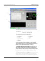
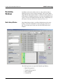
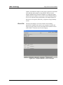
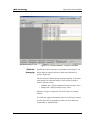
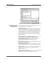
Main Window. . . . . . . . . . . . . . . . . . . . . . . . . . . . . . . . . . . . . . . . . 5-1
Menu Bar . . . . . . . . . . . . . . . . . . . . . . . . . . . . . . . . . . . . . . . . . 5-3
Toolbar. . . . . . . . . . . . . . . . . . . . . . . . . . . . . . . . . . . . . . . . . . . 5-4
Tabs . . . . . . . . . . . . . . . . . . . . . . . . . . . . . . . . . . . . . . . . . . . . . 5-4
Home tab . . . . . . . . . . . . . . . . . . . . . . . . . . . . . . . . . . . . . . 5-4
Run Batch Tab. . . . . . . . . . . . . . . . . . . . . . . . . . . . . . . . . . 5-5
Maintenance Tab . . . . . . . . . . . . . . . . . . . . . . . . . . . . . . . . 5-8
Diagnostics tab . . . . . . . . . . . . . . . . . . . . . . . . . . . . . . . . . 5-9
Acquisition Detail Tab . . . . . . . . . . . . . . . . . . . . . . . . . . 5-12
ii
PN 89-00002-00-071 Rev. C
xMAP Technology
Contents
Status Bar . . . . . . . . . . . . . . . . . . . . . . . . . . . . . . . . . . . . . . . . 5-17
Secondary Windows . . . . . . . . . . . . . . . . . . . . . . . . . . . . . . . . . . . 5-20
Batch Setup Window . . . . . . . . . . . . . . . . . . . . . . . . . . . . . . . 5-20
Analysis Window . . . . . . . . . . . . . . . . . . . . . . . . . . . . . . . . . . 5-22
Errors Tab. . . . . . . . . . . . . . . . . . . . . . . . . . . . . . . . . . . . . 5-23
Standards Tab. . . . . . . . . . . . . . . . . . . . . . . . . . . . . . . . . . 5-24
Samples Tab . . . . . . . . . . . . . . . . . . . . . . . . . . . . . . . . . . . 5-28
Replicate Averaging. . . . . . . . . . . . . . . . . . . . . . . . . . . . . 5-29
Commands. . . . . . . . . . . . . . . . . . . . . . . . . . . . . . . . . . . . . . . . . . . 5-31
Acquire Patient . . . . . . . . . . . . . . . . . . . . . . . . . . . . . . . . . . . . 5-31
Add Batch . . . . . . . . . . . . . . . . . . . . . . . . . . . . . . . . . . . . . . . . 5-31
Alcohol Flush . . . . . . . . . . . . . . . . . . . . . . . . . . . . . . . . . . . . . 5-31
Autoscale . . . . . . . . . . . . . . . . . . . . . . . . . . . . . . . . . . . . . . . . 5-31
Autosize . . . . . . . . . . . . . . . . . . . . . . . . . . . . . . . . . . . . . . . . . 5-31
Backflush . . . . . . . . . . . . . . . . . . . . . . . . . . . . . . . . . . . . . . . . 5-31
CAL1 . . . . . . . . . . . . . . . . . . . . . . . . . . . . . . . . . . . . . . . . . . . 5-31
CAL2 . . . . . . . . . . . . . . . . . . . . . . . . . . . . . . . . . . . . . . . . . . . 5-31
Cancel (Command) . . . . . . . . . . . . . . . . . . . . . . . . . . . . . . . . . 5-31
Cancel All . . . . . . . . . . . . . . . . . . . . . . . . . . . . . . . . . . . . . . . . 5-31
Change Lot . . . . . . . . . . . . . . . . . . . . . . . . . . . . . . . . . . . . . . . 5-31
CON1 . . . . . . . . . . . . . . . . . . . . . . . . . . . . . . . . . . . . . . . . . . . 5-31
CON2 . . . . . . . . . . . . . . . . . . . . . . . . . . . . . . . . . . . . . . . . . . . 5-31
Connect to Instrument. . . . . . . . . . . . . . . . . . . . . . . . . . . . . . . 5-32
Create New Multi-Batch. . . . . . . . . . . . . . . . . . . . . . . . . . . . . 5-32
Delete Batch . . . . . . . . . . . . . . . . . . . . . . . . . . . . . . . . . . . . . . 5-32
Density/Decaying . . . . . . . . . . . . . . . . . . . . . . . . . . . . . . . . . . 5-32
Display Confirmation Screens . . . . . . . . . . . . . . . . . . . . . . . . 5-32
Disconnect from the Instrument . . . . . . . . . . . . . . . . . . . . . . . 5-32
Drain . . . . . . . . . . . . . . . . . . . . . . . . . . . . . . . . . . . . . . . . . . . . 5-32
Eject/Retract . . . . . . . . . . . . . . . . . . . . . . . . . . . . . . . . . . . . . . 5-32
Enable Raw Data Storage . . . . . . . . . . . . . . . . . . . . . . . . . . . . 5-32
Export Batch Data. . . . . . . . . . . . . . . . . . . . . . . . . . . . . . . . . . 5-32
Export CAL. . . . . . . . . . . . . . . . . . . . . . . . . . . . . . . . . . . . . . . 5-32
Export CON . . . . . . . . . . . . . . . . . . . . . . . . . . . . . . . . . . . . . . 5-32
Export Data . . . . . . . . . . . . . . . . . . . . . . . . . . . . . . . . . . . . . . . 5-33
Help. . . . . . . . . . . . . . . . . . . . . . . . . . . . . . . . . . . . . . . . . . . . . 5-33
Import Calibration. . . . . . . . . . . . . . . . . . . . . . . . . . . . . . . . . . 5-33
Import Control . . . . . . . . . . . . . . . . . . . . . . . . . . . . . . . . . . . . 5-33
Import Template . . . . . . . . . . . . . . . . . . . . . . . . . . . . . . . . . . . 5-33
Insert . . . . . . . . . . . . . . . . . . . . . . . . . . . . . . . . . . . . . . . . . . . . 5-33
Invalidate Control . . . . . . . . . . . . . . . . . . . . . . . . . . . . . . . . . . 5-33
Invalidate Standard . . . . . . . . . . . . . . . . . . . . . . . . . . . . . . . . . 5-33
Load Patient List. . . . . . . . . . . . . . . . . . . . . . . . . . . . . . . . . . . 5-33
Log/Linear . . . . . . . . . . . . . . . . . . . . . . . . . . . . . . . . . . . . . . . 5-33
PN 89-00002-00-071 Rev. C
iii
xMAP Technology
Luminex 100 IS User Manual Version 2.3
Maximize/Minimize. . . . . . . . . . . . . . . . . . . . . . . . . . . . . . . .
Next Test . . . . . . . . . . . . . . . . . . . . . . . . . . . . . . . . . . . . . . . .
New Advanced Batch . . . . . . . . . . . . . . . . . . . . . . . . . . . . . .
New Batch . . . . . . . . . . . . . . . . . . . . . . . . . . . . . . . . . . . . . . .
New CAL Targ. . . . . . . . . . . . . . . . . . . . . . . . . . . . . . . . . . . .
New CON Targ. . . . . . . . . . . . . . . . . . . . . . . . . . . . . . . . . . . .
New Lot . . . . . . . . . . . . . . . . . . . . . . . . . . . . . . . . . . . . . . . . .
Open Batch. . . . . . . . . . . . . . . . . . . . . . . . . . . . . . . . . . . . . . .
Open Help . . . . . . . . . . . . . . . . . . . . . . . . . . . . . . . . . . . . . . .
Open Incomplete Batch . . . . . . . . . . . . . . . . . . . . . . . . . . . . .
Open Multi-Batch . . . . . . . . . . . . . . . . . . . . . . . . . . . . . . . . .
Pause . . . . . . . . . . . . . . . . . . . . . . . . . . . . . . . . . . . . . . . . . . .
Previous Test . . . . . . . . . . . . . . . . . . . . . . . . . . . . . . . . . . . . .
Prime . . . . . . . . . . . . . . . . . . . . . . . . . . . . . . . . . . . . . . . . . . .
Print Batch Worklist . . . . . . . . . . . . . . . . . . . . . . . . . . . . . . .
Print Report . . . . . . . . . . . . . . . . . . . . . . . . . . . . . . . . . . . . . .
Recalc. . . . . . . . . . . . . . . . . . . . . . . . . . . . . . . . . . . . . . . . . . .
Replay Batch . . . . . . . . . . . . . . . . . . . . . . . . . . . . . . . . . . . . .
Report Raw Fluorescence . . . . . . . . . . . . . . . . . . . . . . . . . . .
Resume. . . . . . . . . . . . . . . . . . . . . . . . . . . . . . . . . . . . . . . . . .
Sample Probe Down . . . . . . . . . . . . . . . . . . . . . . . . . . . . . . .
Sanitize. . . . . . . . . . . . . . . . . . . . . . . . . . . . . . . . . . . . . . . . . .
Save and Load . . . . . . . . . . . . . . . . . . . . . . . . . . . . . . . . . . . .
Save Only. . . . . . . . . . . . . . . . . . . . . . . . . . . . . . . . . . . . . . . .
Self Diagnostics . . . . . . . . . . . . . . . . . . . . . . . . . . . . . . . . . . .
Show Bead . . . . . . . . . . . . . . . . . . . . . . . . . . . . . . . . . . . . . . .
Single Step . . . . . . . . . . . . . . . . . . . . . . . . . . . . . . . . . . . . . . .
Skip [wells] . . . . . . . . . . . . . . . . . . . . . . . . . . . . . . . . . . . . . .
Soak . . . . . . . . . . . . . . . . . . . . . . . . . . . . . . . . . . . . . . . . . . . .
Start Analysis . . . . . . . . . . . . . . . . . . . . . . . . . . . . . . . . . . . . .
Start (Plate) . . . . . . . . . . . . . . . . . . . . . . . . . . . . . . . . . . . . . .
Statistics . . . . . . . . . . . . . . . . . . . . . . . . . . . . . . . . . . . . . . . . .
Test Sort Orders . . . . . . . . . . . . . . . . . . . . . . . . . . . . . . . . . . .
Validate Control. . . . . . . . . . . . . . . . . . . . . . . . . . . . . . . . . . .
Validate Standard. . . . . . . . . . . . . . . . . . . . . . . . . . . . . . . . . .
View Batch Data . . . . . . . . . . . . . . . . . . . . . . . . . . . . . . . . . .
Warmup . . . . . . . . . . . . . . . . . . . . . . . . . . . . . . . . . . . . . . . . .
Wash . . . . . . . . . . . . . . . . . . . . . . . . . . . . . . . . . . . . . . . . . . .
Zoom . . . . . . . . . . . . . . . . . . . . . . . . . . . . . . . . . . . . . . . . . . .
Procedures . . . . . . . . . . . . . . . . . . . . . . . . . . . . . . . . . . . . . . . . . .
Using the Online Help . . . . . . . . . . . . . . . . . . . . . . . . . . . . . .
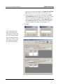
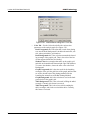
Setting Software Options . . . . . . . . . . . . . . . . . . . . . . . . . . . .
Define General Tab Information . . . . . . . . . . . . . . . . . . .
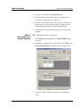
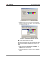
Define Company Information Tab . . . . . . . . . . . . . . . . .
iv
5-33
5-33
5-34
5-34
5-34
5-34
5-34
5-34
5-34
5-34
5-34
5-34
5-35
5-35
5-35
5-35
5-35
5-35
5-35
5-35
5-35
5-35
5-36
5-36
5-36
5-36
5-36
5-36
5-36
5-37
5-37
5-37
5-37
5-37
5-37
5-37
5-37
5-37
5-37
5-38
5-38
5-39
5-39
5-40
PN 89-00002-00-071 Rev. C
xMAP Technology
Contents
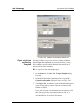
Define Data Export Tab Information . . . . . . . . . . . . . . . . 5-41
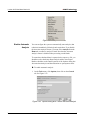
Setting up the Favorites List . . . . . . . . . . . . . . . . . . . . . . . . . . 5-42
Startup Procedures . . . . . . . . . . . . . . . . . . . . . . . . . . . . . . . . . 5-43
Warm Up the System . . . . . . . . . . . . . . . . . . . . . . . . . . . . 5-43
Prime the System . . . . . . . . . . . . . . . . . . . . . . . . . . . . . . . 5-43
Backflush the System . . . . . . . . . . . . . . . . . . . . . . . . . . . . 5-44
Run an Alcohol Flush. . . . . . . . . . . . . . . . . . . . . . . . . . . . 5-44
Run a Wash Cycle . . . . . . . . . . . . . . . . . . . . . . . . . . . . . . 5-44
Set Luminex XYP Instrument Heater Temperature. . . . . 5-45
Calibration Procedures . . . . . . . . . . . . . . . . . . . . . . . . . . . . . . 5-46
Run System xMAP Calibrators . . . . . . . . . . . . . . . . . . . . 5-47
Run System xMAP Controls . . . . . . . . . . . . . . . . . . . . . . 5-49
Selecting Existing CAL or CON Lots . . . . . . . . . . . . . . . 5-50
Importing CAL or CON Lots . . . . . . . . . . . . . . . . . . . . . . 5-50
Exporting CAL or CON lots . . . . . . . . . . . . . . . . . . . . . . 5-51
Batch Setup Procedures . . . . . . . . . . . . . . . . . . . . . . . . . . . . . 5-51
Importing Templates . . . . . . . . . . . . . . . . . . . . . . . . . . . . 5-52
Create a New Batch . . . . . . . . . . . . . . . . . . . . . . . . . . . . . 5-53
Open a Batch . . . . . . . . . . . . . . . . . . . . . . . . . . . . . . . . . . 5-55
Copying and Exporting Batch Data . . . . . . . . . . . . . . . . . 5-55
Clear a Batch from the System. . . . . . . . . . . . . . . . . . . . . 5-55
Replay a Batch . . . . . . . . . . . . . . . . . . . . . . . . . . . . . . . . . 5-56
Delete a Batch . . . . . . . . . . . . . . . . . . . . . . . . . . . . . . . . . 5-57
Create a Multi-Batch . . . . . . . . . . . . . . . . . . . . . . . . . . . . 5-58
Open a Multi-Batch . . . . . . . . . . . . . . . . . . . . . . . . . . . . . 5-59
Process Multiple Plates . . . . . . . . . . . . . . . . . . . . . . . . . . 5-60
Re-Run or Recover Incomplete Batch . . . . . . . . . . . . . . . 5-61
Scan in Samples With a Barcode Reader . . . . . . . . . . . . . 5-61
Add a Patient List. . . . . . . . . . . . . . . . . . . . . . . . . . . . . . . 5-62
Edit a Patient List . . . . . . . . . . . . . . . . . . . . . . . . . . . . . . . 5-63
Assign Sample Dilution Factors. . . . . . . . . . . . . . . . . . . . 5-64
Create a New Advanced Batch. . . . . . . . . . . . . . . . . . . . . 5-65
Managing Assay Lots . . . . . . . . . . . . . . . . . . . . . . . . . . . . . . . 5-71
Create a New Lot . . . . . . . . . . . . . . . . . . . . . . . . . . . . . . . 5-71
Edit Lot Information on an Unused Template . . . . . . . . . 5-73
Edit Lot Information on a Used Template . . . . . . . . . . . . 5-74
Import Lot to an Existing Template . . . . . . . . . . . . . . . . . 5-74
Export a Lot from an Existing Template . . . . . . . . . . . . . 5-75
Analyzing Batches and Multi-Batches . . . . . . . . . . . . . . . . . . 5-76
Customize Data Analysis Settings . . . . . . . . . . . . . . . . . . 5-77
Enable Automatic Analysis . . . . . . . . . . . . . . . . . . . . . . . 5-82
Analyze Processed Batch Data. . . . . . . . . . . . . . . . . . . . . 5-83
View Detailed Test Analysis . . . . . . . . . . . . . . . . . . . . . . 5-83
Validating or Invalidating Standards and Controls . . . . . 5-83
Change Lot . . . . . . . . . . . . . . . . . . . . . . . . . . . . . . . . . . . . 5-85
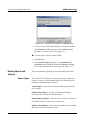
Running Reports and Analyses. . . . . . . . . . . . . . . . . . . . . . . . 5-86
Report Types . . . . . . . . . . . . . . . . . . . . . . . . . . . . . . . . . . 5-86
Export Batch Data . . . . . . . . . . . . . . . . . . . . . . . . . . . . . . 5-89
Print Data Analysis Report. . . . . . . . . . . . . . . . . . . . . . . . 5-89
PN 89-00002-00-071 Rev. C
v
xMAP Technology
Luminex 100 IS User Manual Version 2.3
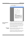
Database Management Procedures . . . . . . . . . . . . . . . . . . . .
Back Up the Database . . . . . . . . . . . . . . . . . . . . . . . . . . .
Delete Database Entries . . . . . . . . . . . . . . . . . . . . . . . . .
Restore Database Data. . . . . . . . . . . . . . . . . . . . . . . . . . .
Maintenance Procedures . . . . . . . . . . . . . . . . . . . . . . . . . . . .
Drain the Analyzer . . . . . . . . . . . . . . . . . . . . . . . . . . . . .
Run Self-Diagnostics. . . . . . . . . . . . . . . . . . . . . . . . . . . .
Using the Cleanup Utility . . . . . . . . . . . . . . . . . . . . . . . .
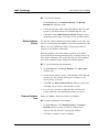
Daily Shutdown Procedures. . . . . . . . . . . . . . . . . . . . . . . . . .
Sanitize the System . . . . . . . . . . . . . . . . . . . . . . . . . . . . .
Run a Wash Command . . . . . . . . . . . . . . . . . . . . . . . . . .
Perform a Soak Command . . . . . . . . . . . . . . . . . . . . . . .
Exit Luminex IS 2.3 Software. . . . . . . . . . . . . . . . . . . . .
Maintenance and Cleaning
5-90
5-90
5-91
5-91
5-92
5-93
5-94
5-94
5-96
5-96
5-96
5-97
5-97
6-1
Daily Maintenance . . . . . . . . . . . . . . . . . . . . . . . . . . . . . . . . . . . . . 6-1
Before Running Samples . . . . . . . . . . . . . . . . . . . . . . . . . . . . . 6-1
After Running Samples . . . . . . . . . . . . . . . . . . . . . . . . . . . . . . 6-2
Routine Tasks . . . . . . . . . . . . . . . . . . . . . . . . . . . . . . . . . . . . . . . . . 6-2
Sheath and Waste Fluids . . . . . . . . . . . . . . . . . . . . . . . . . . . . . 6-2
Refill the Sheath Fluid Container . . . . . . . . . . . . . . . . . . . 6-3
Empty the Waste Container. . . . . . . . . . . . . . . . . . . . . . . . 6-3
Weekly . . . . . . . . . . . . . . . . . . . . . . . . . . . . . . . . . . . . . . . . . . . . . . 6-3
Visual Inspection . . . . . . . . . . . . . . . . . . . . . . . . . . . . . . . . . . . 6-3
Run Self-Diagnostics . . . . . . . . . . . . . . . . . . . . . . . . . . . . . . . . 6-3
Clean Sample Probe. . . . . . . . . . . . . . . . . . . . . . . . . . . . . . . . . 6-3
Flush the System . . . . . . . . . . . . . . . . . . . . . . . . . . . . . . . . . . . 6-4
Monthly . . . . . . . . . . . . . . . . . . . . . . . . . . . . . . . . . . . . . . . . . . . . . 6-4
Clean the Sample Probe . . . . . . . . . . . . . . . . . . . . . . . . . . . . . . 6-4
Clean Exterior Surfaces . . . . . . . . . . . . . . . . . . . . . . . . . . . . . . 6-4
Calibration and System Controls . . . . . . . . . . . . . . . . . . . . . . . 6-5
Every Six Months . . . . . . . . . . . . . . . . . . . . . . . . . . . . . . . . . . . . . . 6-5
Luminex 100 Analyzer Air Intake Filter . . . . . . . . . . . . . . . . . 6-5
Luminex XYP Instrument Air Intake Filter. . . . . . . . . . . . . . . 6-6
Syringe Seal . . . . . . . . . . . . . . . . . . . . . . . . . . . . . . . . . . . . . . . 6-8
Luminex 100 Analyzer Ventilation Filter . . . . . . . . . . . . . . . . 6-9
Annually . . . . . . . . . . . . . . . . . . . . . . . . . . . . . . . . . . . . . . . . . . . . 6-10
Sheath Filter . . . . . . . . . . . . . . . . . . . . . . . . . . . . . . . . . . . . . . 6-10
As required . . . . . . . . . . . . . . . . . . . . . . . . . . . . . . . . . . . . . . . . . . 6-11
Fuses . . . . . . . . . . . . . . . . . . . . . . . . . . . . . . . . . . . . . . . . . . . 6-11
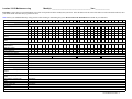
Maintenance Log . . . . . . . . . . . . . . . . . . . . . . . . . . . . . . . . . . . . . 6-13
Troubleshooting
7-1
Troubleshooting the Luminex 100 IS System . . . . . . . . . . . . . . . . 7-1
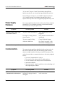
Power Supply Problems . . . . . . . . . . . . . . . . . . . . . . . . . . . . . . . . . 7-2
Communication . . . . . . . . . . . . . . . . . . . . . . . . . . . . . . . . . . . . . . . 7-2
vi
PN 89-00002-00-071 Rev. C
xMAP Technology
Contents
Pressurization . . . . . . . . . . . . . . . . . . . . . . . . . . . . . . . . . . . . . . . . . 7-3
Fluid Leaks . . . . . . . . . . . . . . . . . . . . . . . . . . . . . . . . . . . . . . . . . . . 7-4
Sample Probe. . . . . . . . . . . . . . . . . . . . . . . . . . . . . . . . . . . . . . . . . . 7-5
Calibration and Control Problems. . . . . . . . . . . . . . . . . . . . . . . . . . 7-7
Acquisition Problems . . . . . . . . . . . . . . . . . . . . . . . . . . . . . . . . . . . 7-9
Bead Detail Irregularities . . . . . . . . . . . . . . . . . . . . . . . . . . . . . . . 7-10
Error States . . . . . . . . . . . . . . . . . . . . . . . . . . . . . . . . . . . . . . . . . . 7-13
System Error Messages . . . . . . . . . . . . . . . . . . . . . . . . . . . . . . . . . 7-13
Sample Error Messages . . . . . . . . . . . . . . . . . . . . . . . . . . . . . . . . . 7-15
Luminex SD Problems . . . . . . . . . . . . . . . . . . . . . . . . . . . . . . . . . 7-18
Filter . . . . . . . . . . . . . . . . . . . . . . . . . . . . . . . . . . . . . . . . . . . . 7-18
Malfunction. . . . . . . . . . . . . . . . . . . . . . . . . . . . . . . . . . . . . . . 7-18
Draining the Reservoir . . . . . . . . . . . . . . . . . . . . . . . . . . . . . . 7-18
Verification . . . . . . . . . . . . . . . . . . . . . . . . . . . . . . . . . . . . . . . . . . 7-19
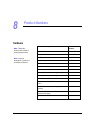
Product Numbers
8-1
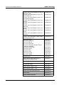
Hardware . . . . . . . . . . . . . . . . . . . . . . . . . . . . . . . . . . . . . . . . . . . . . 8-1
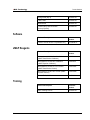
Software. . . . . . . . . . . . . . . . . . . . . . . . . . . . . . . . . . . . . . . . . . . . . . 8-3
xMAP Reagents. . . . . . . . . . . . . . . . . . . . . . . . . . . . . . . . . . . . . . . . 8-3
Training . . . . . . . . . . . . . . . . . . . . . . . . . . . . . . . . . . . . . . . . . . . . . . 8-3
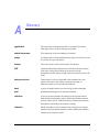
Glossary
A-1
Luminex 100 IS System Installation
B-1
Overview . . . . . . . . . . . . . . . . . . . . . . . . . . . . . . . . . . . . . . . . . . . . B-1
Luminex 100 IS System Setup . . . . . . . . . . . . . . . . . . . . . . . . . . . B-1
Connect the Luminex 100 analyzer and
Luminex XYP to the PC . . . . . . . . . . . . . . . . . . . . . . . . . . . . . B-3
Install the Luminex XYP Instrument Sample Probe . . . . . . . B-6
Power On System Components . . . . . . . . . . . . . . . . . . . . . . . B-8
Accept the Luminex 100 IS 2.3 Software
License Agreement . . . . . . . . . . . . . . . . . . . . . . . . . . . . . . . . . B-8
Adjust the Sample Probe Vertical Height. . . . . . . . . . . . . . . . B-8
Install the Luminex XYP Instrument Reservoir . . . . . . . . . . . B-9
Calibrate and Verify the System. . . . . . . . . . . . . . . . . . . . . . B-10
Install the SD System . . . . . . . . . . . . . . . . . . . . . . . . . . . . . . B-10
Install the Luminex XYP Instrument Heater Block . . . . . . . B-13
Luminex 100 IS 2.3 Software Installation. . . . . . . . . . . . . . . . . . B-14
Luminex 100 Version 1.7 with Windows 98 to
Luminex 100 IS Version 2.3. . . . . . . . . . . . . . . . . . . . . . . . . B-15
Install New PC . . . . . . . . . . . . . . . . . . . . . . . . . . . . . . . . B-15
Install Luminex 100 IS 2.3 Software . . . . . . . . . . . . . . . B-15
Verify Successful Upgrade. . . . . . . . . . . . . . . . . . . . . . . B-16
Luminex 100 Version 1.7 with Windows 2000 to
Luminex 100 IS Version 2.3. . . . . . . . . . . . . . . . . . . . . . . . . B-17
PN 89-00002-00-071 Rev. C
vii
Luminex 100 IS User Manual Version 2.3
xMAP Technology
Archive “My Sessions” folder. . . . . . . . . . . . . . . . . . . . . B-17
Remove Luminex LMAT Software . . . . . . . . . . . . . . . . B-17
Remove Luminex 100 Version 1.7 Software . . . . . . . . . B-18
Install Luminex 100 IS 2.3 Software. . . . . . . . . . . . . . . . B-19
Luminex 100 IS Version 2.1/2.2 to Luminex 100 IS
Version 2.3. . . . . . . . . . . . . . . . . . . . . . . . . . . . . . . . . . . . . . . B-19
Backup Luminex 100 IS 2.1 or 2.2 Database . . . . . . . . . B-19
Remove Luminex 100 IS 2.1 or 2.2 . . . . . . . . . . . . . . . . B-20
Install Luminex 100 IS 2.3 Software. . . . . . . . . . . . . . . . B-20
Luminex 100 IS 2.3 Firmware Installation. . . . . . . . . . . . . . . . . . B-21
Firmware Upgrade Cable Configurations . . . . . . . . . . . . . . . B-21
Luminex 100 Analyzer Firmware Upgrade . . . . . . . . . . . . . . B-22
Connect Cable . . . . . . . . . . . . . . . . . . . . . . . . . . . . . . . . . B-22
Upgrade Firmware. . . . . . . . . . . . . . . . . . . . . . . . . . . . . . B-22
Verify Successful Firmware Upgrade . . . . . . . . . . . . . . B-23
Update Interface Cable . . . . . . . . . . . . . . . . . . . . . . . . . . B-23
Luminex XYP Instrument Firmware Update. . . . . . . . . . . . . B-24
Update Firmware. . . . . . . . . . . . . . . . . . . . . . . . . . . . . . . B-24
Verify Successful Firmware Upgrade . . . . . . . . . . . . . . . B-24
Luminex SD System Firmware Update . . . . . . . . . . . . . . . . . B-25
Update Firmware . . . . . . . . . . . . . . . . . . . . . . . . . . . . . . . . . . B-25
Verify Successful Firmware Upgrade . . . . . . . . . . . . . . . B-25
Network Installation Advisory . . . . . . . . . . . . . . . . . . . . . . . . . . . B-26
Prepare System for First Use . . . . . . . . . . . . . . . . . . . . . . . . . . . . B-26
Installation Drawing . . . . . . . . . . . . . . . . . . . . . . . . . . . . . . . . . . . B-27
Output.CSV
C-1
Overview . . . . . . . . . . . . . . . . . . . . . . . . . . . . . . . . . . . . . . . . . . . . C-1
Overall Design . . . . . . . . . . . . . . . . . . . . . . . . . . . . . . . . . . . . . . . . C-1
Blank Lines . . . . . . . . . . . . . . . . . . . . . . . . . . . . . . . . . . . . . . . C-2
Field Definitions . . . . . . . . . . . . . . . . . . . . . . . . . . . . . . . . . . . C-2
Statistics Definitions . . . . . . . . . . . . . . . . . . . . . . . . . . . . . . . . C-4
Statistics Column Definitions . . . . . . . . . . . . . . . . . . . . . . . . . C-5
Luminex 100 IS OUTPUT.CSV file with no
additional features enabled . . . . . . . . . . . . . . . . . . . . . . . . . . . . . . C-7
Luminex 100 IS OUTPUT.CSV file with all
additional features enabled . . . . . . . . . . . . . . . . . . . . . . . . . . . . . . . C-8
Index
viii
Index-1
PN 89-00002-00-071 Rev. C
1
Introduction
About This Manual
This manual provides you with information to understand and use the
Luminex® 100™ IS system. It consists of multiple chapters and
appendices that take you from this introduction to complete system
operation.
The manual’s text and figures offer examples when necessary.
Procedures are presented as step-by-step instructions. Glossary and
index sections assist as references.
The conventions in this manual assume that the reader has a basic
familiarity with computers, xMAP® technology, and a knowledge of
Microsoft® Windows® software. We typically document the
common methods of accessing a command, such as from the main
menu bar, from the toolbar, and from menus that appear when you
right-click an area of the screen. Refer to the Glossary appendix for
unfamiliar terminology.
The Luminex 100 IS
2.3 System
Intended Use
PN 89-00002-00-071 Rev. C
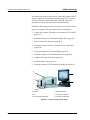
The Luminex 100 IS 2.3 system is a benchtop system consisting of
the Luminex 100 analyzer, computer, monitor, keyboard, mouse,
Luminex XY Platform instrument (Luminex XYP™), Luminex
Sheath Delivery System (Luminex SD™), software, barcode reader,
sheath and waste containers, and xMAP technology reagents.
The Luminex software is designed to use xMAP technology with
assay kits available through kit manufacturers.The Luminex 100 IS
2.3 system performs a wide range of xMAP technology-based
laboratory tests, measuring biomolecular reactions on the surface of
xMAP microspheres. This system is intended for general
laboratory use.
1-1
xMAP Technology
Luminex 100 IS User Manual Version 2.3
Technical Support
Luminex Technical Support representatives are ready to help you,
particularly when the system or software cause any questions or
problems. If the question or problem relates to materials from the
assay kit, you should contact the kit provider directly.
Luminex Technical Support is available to users in the U.S. and
Canada by calling 1-877-785-BEAD (-2323) between the hours of
7:00 a.m. and 7:00 p.m. Central Time, Monday through Friday. Users
outside of the U.S., Canada, Europe can contact us at +1 512-3814397 between the hours of 7:00 a.m. to 7:00 p.m. Central Time,
Monday through Friday. Inquiries may also be sent by email to
[email protected].
Luminex Technical Support is also available to users in Europe by
calling +31-162408333 between the hours of 8:30 and 5:30, Central
European Time, Monday through Friday. Email inquiries in Europe
can be sent to [email protected].
Luminex Website
Additional information is available on the Luminex website. Search
on the desired topic or navigate through menus. Also, review the
website’s FAQ section.
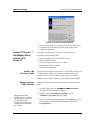
To access Luminex website FAQ section:
In your browser’s address field, enter:
http://luminexcorp.custhelp.com. This address takes you
directly to the FAQ section.
1-2
PN 89-00002-00-071 Rev. C
2
Safety
Symbols
Please become familiar with the information in this chapter before
using the equipment. Do not perform procedures on your Luminex
100 IS 2.3 system that are not specifically contained in this manual,
unless you are directed to do so by Luminex Technical Support.
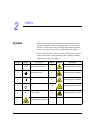
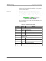
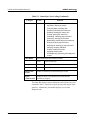
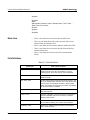
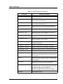
These symbols describe warnings, cautions, and general information
used in the operation of this instrument. These symbols are further
defined under “Safety Precautions.”
Number
Symbol
Description
Number
Symbol
Description
1
Alternating current (ac)
7
Warning (refer to manual)
2
Protective ground
8
Warning (refer to manual)
3
On
9
Warning (refer to manual)
4
Off
10
Warning (refer to manual)
Serial number
11
Warning (refer to manual)
5
SN
6
PN 89-00002-00-071 Rev. C
Warning (refer to manual)
2-1
xMAP Technology
Luminex 100 IS User Manual Version 2.3
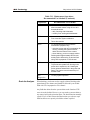
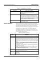
Warnings and Notes
Informational notes and warnings appear in this manual.
Note: A note provides general helpful information. No safety or
performance issues are involved.
Caution: This message is used in cases where the hazard is minor or
only potential hazard is present. Failure to comply with the caution
may result in potentially hazardous conditions.
Warning: This message is used in cases where danger to the
operator or to the performance of the instrument is present. Failure to
comply with the warning may result in incorrect performance,
instrument failure, invalid results, or hazard to the operator.
Danger: This message is used in cases where significant risk of
serious injury or death is present.
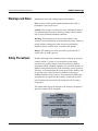
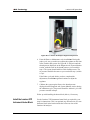
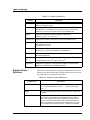
Safety Precautions
Read the following safety information before setting up or using the
Luminex 100 IS 2.3 system. A user should be present during
operation. This system contains electrical, mechanical, and laser
components which, if handled improperly, are potentially harmful. In
addition, biological hazards may be present during system operation.
Therefore, we recommend that all system users become familiar with
the specific safety advisories below, in addition to adhering to
standard laboratory safety practices. The protection provided by the
equipment may be impaired or the warranty voided if the system is
used in a manner not specified by the instructions or by Luminex
Corporation.
This caution label appears on the back of the Luminex 100 analyzer
and on the Luminex XYP instrument.
.
Figure 2-1 Fuse Caution Label
2-2
PN 89-00002-00-071 Rev. C
xMAP Technology
Safety
Do not perform any maintenance or cleaning of the system’s
electrical components, with the exception of replacing fuses.
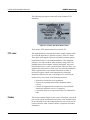
This label appears on the back panel of the Luminex 100 analyzer
and on the back panel of the Luminex XYP instrument.
Figure 2-2 CE Label
The Luminex 100 analyzer and the Luminex XYP instrument
comply with European Union (EU) safety requirements and,
therefore, may be marketed in the Europe Single Market.
This voltage label appears on the back of the Luminex 100 analyzer:
Figure 2-3 Luminex 100 Serial Number Label
The Luminex 100 analyzer has been tested by Underwriter
Laboratories, Inc.® (UL).
PN 89-00002-00-071 Rev. C
2-3
Luminex 100 IS User Manual Version 2.3
xMAP Technology
The following label appears on the back of the Luminex XYP
instrument.
Figure 2-4 Luminex XYP Serial Number Label
The Luminex XYP instrument has been tested by UL.
FCC Label
This equipment has been tested and found to comply with the limits
for a Class B digital device, pursuant to part 15 of the FCC Rules.
These limits are designed to provide reasonable protection against
harmful interference in a residential installation. This equipment
generates, uses and can radiate radio frequency energy and, if not
installed and used in accordance with the instructions, may cause
harmful interference to radio communications. However, there is no
guarantee that interference will not occur in a particular installation.
If this equipment does cause harmful interference to radio or
television reception, which can be determined by turning the
equipment off and on, the user is encouraged to try to correct the
interference by one or more of the following measures:
• Reorient or relocate the receiving antenna.
• Increase the separation between the equipment and the
receiver.
• Connect the equipment into an outlet on a circuit different
from that to which the receiver is connected.
• Consult the dealer or an experienced radio/TV technician for
help.
Fluidics
2-4
This system contains fluidics. In the event of a fluid leak, turn off all
power to the system and disconnect all power cords. Remember that
the on/off switch is not a disconnect means; the power cord must be
removed from the outlet. Contact Luminex Corporation for further
information.
PN 89-00002-00-071 Rev. C
xMAP Technology
Safety
You must monitor waste levels manually. Do not allow the waste
container to overflow! Empty the waste container each time the
sheath fluid container is filled. Do not place the waste container on
top of the instrument.
Warning: If biological samples have been tested with the system,
use your standard laboratory safety practices when handling
system waste.
Luminex 100 Analyzer
Laser
The Luminex 100 IS system classifies per FDA 21 CFR 1040.10 and
1040.11 as a Class II laser product consisting of a Class I laser
product (Luminex 100 analyzer) and a Class II laser product
(barcode reader).
Figure 2-5 Laser Product Class Label
United States and international regulations require the following
warnings to appear on the instrument during operation and
maintenance.
This label appears on the back panel of the Luminex 100 analyzer.
Figure 2-6 Laser Radiation Caution Label
Under NO circumstances should you remove the Luminex 100
analyzer cover! When performing routine maintenance, turn power
to the Luminex 100 analyzer OFF and the disconnect the power cord.
PN 89-00002-00-071 Rev. C
2-5
Luminex 100 IS User Manual Version 2.3
xMAP Technology
All laser apertures are located within the Luminex 100 analyzer and
are contained within a protective housing. This label appears on the
optics cover within the Luminex 100 analyzer.
Figure 2-7 Laser Class Label
Warning — Use of controls or adjustments or performance of
procedures other than those specified herein may result in
hazardous radiation exposure.
Attention — L’utilisation des commandes ou réglages ou
l’exécution des procédures autres que celles spécifiées dans les
présentes prescriptions peuvent entraîner d’une exposition à un
rayonnement dangereux.
This label appears above the laser apertures located inside the optics
enclosure inside the Luminex 100 analyzer.
Figure 2-8 Avoid Exposure Label
2-6
PN 89-00002-00-071 Rev. C
xMAP Technology
Barcode Reader Laser
Safety
This label is attached to the barcode reader.
Figure 2-9 Barcode Reader Laser Label
Do not stare into the beam or shine it into other people’s eyes.
Mechanical
Warning: During operation, this system contains exposed,
moving parts. Risk of personal injury is present. Observe all
warnings and cautions.
Warning: During operation, this system contains exposed,
moving parts which could result in puncture hazard. Risk of
personal injury is present. Keep hands and fingers away from the
Luminex XYP instrument slot during operation.
Warning: During operation, this system contains exposed,
moving parts which could result in pinch point hazard. Risk of
personal injury is present. Keep hands and fingers away from the
Luminex XYP instrument slot during operation.
Note: Access doors must be
closed while operating the
Luminex 100 analyzer; the
operator must be present during
operation.
Biological
Warning: Human and animal samples may contain biohazardous
infectious agents.
Where exposure (including aerosol) to potentially biohazardous
material exists, follow appropriate biosafety procedures and use
personal protective equipment, such as gloves, gowns, laboratory
coats, face shields, or mask and eye protection, and ventilation
devices.
Observe all local, state, and federal biohazard handling
regulations when disposing of biohazardous waste material.
PN 89-00002-00-071 Rev. C
2-7
Luminex 100 IS User Manual Version 2.3
xMAP Technology
Heat
Warning: The heater plate of the Luminex XYP instrument may
be hot and could cause personal injury if touched. Do not touch
the heater plate.
Blue Indicator Light
2-8
The blue light above the Luminex 100 analyzer sample arm indicates
the on/off status of the Luminex 100 analyzer, and is harmless. The
blue light-emitting diode (LED) does not emit light in the UV
spectrum.
PN 89-00002-00-071 Rev. C
xMAP Technology
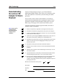
Decontaminating
the Luminex 100
Analyzer for Return
Shipment
Safety
Luminex Technical Support will give you a Return Material
Authorization (RMA) number if they direct you to return the system.
They will explain how to return the system according to Luminex
procedures.
The accessible surfaces and the internal fluidics system must be
sanitized and decontaminated before returning the analyzer. This is
particularly important when biohazardous samples have been run.
Make a copy of this page to fill out and return with the system.
Complete the following checklist, signed and dated, and return it
with the Luminex 100 analyzer.
Note: It is the user’s
responsibility to
decontaminate the
analyzer before
shipment.
1.
Remove all specimens, disposables, and reagents from the system.
2.
Disconnect the sheath line going from the SD system to the analyzer.
3.
Connect a sheath bottle filled with a solution of 10% to 20% household
bleach and water to the analyzer.
4.
Sanitize the system using the Sanitize command on the main screen of
the system. Follow this by washing twice with distilled water.
5.
Disconnect the system from AC power by turning off the power switch
on the rear of the system, then unplugging the analyzer power cord
from the wall source.
6.
Disconnect the SD system and waste and sheath containers.
7.
Rinse the waste container with 10% to 20% household bleach solution
and drain.
8.
Wash all exterior surfaces with a mild detergent, followed by a 10% to
20% bleach solution.
9.
Open both front doors of the analyzer and clean all accessible surfaces
with mild detergent followed by a 10% to 20% bleach solution.
10. Pack the system within a biohazard bag, place it in the corrugated box,
then insert it in its original packaging or an approved shipping
container. Attach this checklist to the top of the corrugated box prior to
packaging in the crate.
Was there an internal leak in the system?
Yes
No
Print Name:
Signature:
Date:
PN 89-00002-00-071 Rev. C
Instrument Serial No.
2-9
Luminex 100 IS User Manual Version 2.3
2 - 10
xMAP Technology
PN 89-00002-00-071 Rev. C
3
The System
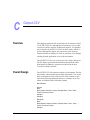
Theory of Operation
Luminex 100 IS technology is based on flow cell fluorometry with
Luminex-developed innovations. The fluidics, optics, robotics,
temperature control, software, and xMAP microspheres work
together to enable simultaneous analysis of up to 100 analytes in a
single test sample. Assay analysis requiring temperature control is
provided through the Luminex XYP instrument heater block.
There are two fluidics paths in the Luminex 100 analyzer. The first
path involves a syringe-driven mechanism that controls the sample
uptake. This mechanism permits small sample uptake volumes from
small reaction volumes. The syringe-driven system transports a
specified volume of sample from a sample container to the cuvette.
The sample is injected into the cuvette at a steady rate for analysis.
Following analysis, the sample path is automatically purged with
sheath buffer by the second fluidics path. This process removes
residual sample within the tubing, valves, and probe. The second
fluidics path is driven by positive air pressure and supplies sheath
fluid to the cuvette and sample path.
Sheath fluid is the delivery medium of the sample to the optics
component. The analysis sample is acquired using a sample probe
from a 96-well microtiter plate via the Luminex XYP instrument and
injected into the base of the cuvette. The sample then passes through
with sheath fluid at a reduced rate resulting in a narrow sample core
to ensure that each microsphere is illuminated individually. The
sample injection rate is such that the xMAP microspheres are
introduced to the optics path as a series of single events. The
Luminex SD system lets you run samples continuously without
refilling sheath bottles. It automatically draws sheath from a non
pressurized bulk sheath container to constantly maintain a reservoir
PN 89-00002-00-071 Rev. C
3-1
xMAP Technology
Luminex 100 IS User Manual Version 2.3
of pressurized sheath fluid. A single 20 liter sheath container
provides enough fluid for 48 hours or more of normal operation.
The optics assembly consists of two lasers. One laser excites the dye
mixture inside the xMAP microspheres and the second laser excites
the fluorosphere bound to the surface of the xMAP microspheres.
Avalanche photo diode detectors measure the excitation emission
intensities of the color coding classification dye mixtures inside the
xMAP microspheres and a photomultiplier tube detects the excitation
emission intensity of the reporter molecule bound to the surface of
the xMAP microspheres. High speed digital signal processors and
advanced computer algorithms provide analysis of the xMAP
microspheres as they are processed through the Luminex 100
analyzer. Results of the analyses are processed and provided in a
report format.
Hardware
The Luminex 100 IS system includes the following hardware:
•
•
•
•
•
•
•
•
•
•
•
•
•
•
•
•
•
•
•
•
•
•
3-2
Luminex 100 analyzer
Computer (PC), monitor, and accessories
Luminex XYP instrument
Luminex Sheath Delivery System (Luminex SD™)
Power cables
Alignment guide
Two long sample probes
Luminex XYP instrument sample probe
Reservoir
Shield
Heater block
Sheath fluid container
Waste container
Sheath fluid line
Air line
Sheath fluid intake line
Communications: 1 serial communication cable
Communications: 1 USB communication cable
Communications: 1 CANBUS communication cable (short
cable)
Barcode reader
Sample probe height alignment kit
3/32 Hexdrive, Balldriver wrench
PN 89-00002-00-071 Rev. C
xMAP Technology
xMAP Technology
Reagents
Required
Laboratory
Reagents
Luminex 100 IS 2.3
Software
The System
•
•
•
•
•
Classification calibration microspheres (CAL1)
Reporter calibration microspheres (CAL2)
Classification control microspheres (CON1)
Reporter control microspheres (CON2)
Sheath fluid
•
•
•
Household bleach
70% isopropanol or 70% ethanol
Mild detergent
Luminex 100 IS 2.3 software provides complete control of the
system and performs data analysis. Your Luminex 100 IS 2.3 system
is preloaded with the Luminex software. However, we supply a
software CD should you need to reinstall the software.
This software requires a dedicated system. Unauthorized additional
software is prohibited and may result in improper operation of the
system.
Luminex 100 IS
Performance
Specification
Speed
•
•
•
•
•
•
•
•
•
•
•
•
PN 89-00002-00-071 Rev. C
USB communications link for fast data transfer
Automatic transfer of assay templates and new reagent
information into the system via a large capacity read/write CD
Installation: < 4 hours
System calibration: < 10 minutes
System controls: < 10 minutes
Barcode reader entry of sample IDs
Automatic post-analysis
Analyze one 96-well plate/hour depending on manufacturer’s kit
Up to 100 xMAP microsphere sets per sample
Sheath flowrate: 90 µL/sec ± 5 µL
Sample injection rate into detector area: 1 µL/sec ± 0.05 µL
System warmup: 30 minutes. Systems that remain inactive for at
least four hours will require a warm-up to restart the lasers. After
3-3
xMAP Technology
Luminex 100 IS User Manual Version 2.3
acquiring sample, running system calibrators, running system
controls, and warming up the instrument, the system resets the
four-hour internal clock.
Accuracy and Precision
•
•
•
•
•
•
Sensitivity
•
•
Capacity
Detect 1000 fluorochromes phycoerythrin (PE) per xMAP
microsphere
Reporter channel dynamic range: 3.5 decades of detection
The specifications below reflect minimum capacity values:
•
•
•
•
•
•
•
•
•
•
•
•
•
3-4
Sample uptake volume: ± 5%
Classification of xMAP microspheres: > 80%
Misclassification of xMAP microspheres: ≤ 2% - may vary by
xMAP microsphere product lines. Refer to the specific product
information sheet for further details.
Temperature control: 0°C to + 2°C of target
Internal sample carry over: < 0.9%
Soluble background fluorescence emission at 575 nm
automatically subtracted from fluorescence intensity values
10 GB hard drive
100 MB read/write CD ROM
Analyze multiple 96-well plates per batch
Analyze multiple assay templates per plate
Distinguish a minimum of 1 to a maximum of 100 unique xMAP
microsphere sets in a single sample
Detect and distinguish surface reporter fluorescence emissions at
575 nm on the surface of 1-100 unique xMAP microspheres sets
in a single sample
Sample core: 15-20 µm core at 1 µL/sec. sample inject rate
Maintain samples at a constant temperature from 35°C to 55°C
(95°F to 131°F)
Automatic sampling from a 96-well plate
Start sampling from any well position
Sheath container and waste container hold enough volume to run
up to two 96-well plates between refills
Microtiter plates with 96 wells must be compatible with the
Luminex XYP instrument plate holder. The following microtiter
plate types are compatible with the Luminex XYP instrument
plate holder: flatbottom, conical, round, filter bottom, half plates
[overall height no more than 0.75” (19 mm)], any color
Microtiter plates with 96 wells must be compatible with
Luminex XYP instrument heater block temperature from 35°C to
PN 89-00002-00-071 Rev. C
xMAP Technology
The System
55°C (95°F to 131°F) when performing heated assays and using
the heater block
Luminex 100
Analyzer General
•
•
•
•
•
•
•
•
•
•
•
Optics
•
•
•
•
•
Fluidics
Electronics
PN 89-00002-00-071 Rev. C
Indoor use only
Operating temperature: 15°C to 30°C (59°F to 86°F)
Humidity: 20% to 80%, noncondensing
Altitude: Operation up to 2400 m (7874 ft.) above mean sea level
Physical dimensions: 43 cm (17 inches) W x 50.5 cm (20 inches)
D x 24.5 cm (9.5 inches) H
Weight: maximum of 25 kg (60 lbs.)
UL installation category: UL Installation Category II, as defined
in Annex J of UL 61010A-1
Pollution degree: UL Pollution Degree 2, as defined in Section
3.7.3.2 of UL 61010A-1
Shipping and storage: The allowable shipping and storage
temperature and humidity ranges are 0°C to + 50°C and 20-80%
noncondensing, respectively
Input voltage range: 100 - 120 V~ ± 10%, 1.4 Amp, and 200-240
V~ ± 10%, 0.8 Amp, 47-63 Hz.
AC inlet fuse: 3 Amp, 250 V~, fast acting
Reporter laser: 532 nm, nominal output 10-15 mW, maximum
500 mW, frequency-doubled diode; mode of operation,
continuous wave (CW)
Classification laser: 635 nm, 9.1 mW ± 6%, maximum output 25
mW, diode; mode of operation, continuous wave (CW)
Reporter detector: Photomultiplier tube, detection bandwidth of
565-585 nm
Classification detector: Avalanche photo diodes with temperature
compensation
Doublet discrimination detector: Avalanche photo diodes with
temperature compensation
•
•
•
•
Sheath flow rate 90 µL ± 5 µL/second
Cuvette: 200 micron square flow channel
Sample injection rate: 1 µL/second
Sample uptake volume: 20-200 µL
•
•
•
Reporter channel detection: A/D resolution 14 bits
Communications interface: USB
Luminex XYP instrument, communications interface: RS 232
3-5
xMAP Technology
Luminex 100 IS User Manual Version 2.3
Luminex XYP
Instrument General
•
•
•
•
•
•
•
•
•
•
Luminex SD System
General
•
•
•
•
•
•
•
•
•
PC Specifications
Ambient temperature: 15°C to 30°C (59°F to 86°F)
Humidity: 20% to 80%, noncondensing
Altitude: operation up to 2400 m (7874 ft) above mean sea level
Physical dimensions: 44 cm (17.25 inches) W x 60 cm (23.5
inches) D x 8 cm (3 inches) H
Weight: 15 kg (33 lbs.)
UL installation category: UL Installation Category II, as defined
in Annex J of UL 61010A-1
Pollution degree: UL Pollution Degree 2, as defined in Section
3.7.3.2 of UL 61010A-1
Heater operating range: 35°C to 55°C (95°F to 131°F) with
tolerance 0°C to +2°C
Input voltage range: 100-240 V~ ± 10%, 1.8 Amps, 47-63 Hz
AC inlet fuse: 3 A, 250 V~, fast acting
Ambient temperature: 15°C to 30°C (59° to 86°F)
Humidity: 20% to 80%, noncondensing
Altitude: designed to operate at up to 2400m (7874 feet) above
mean sea level
Physical dimensions: 20 cm (8 inches) W x 30 cm (11.75 inches)
D x 24.75 cm (9.75 inches) H
Weight: 9 kg (20 lbs)
UL installation category: UL Installation Category II, as defined
in Annex J of UL 61010A-1
Pollution degree: UL Pollution Degree 2, as defined in Section
3.7.3.2 of UL 61010A-1
Input voltage range: 100-240 V~ ± 10%, 0.4 Amps, 47-63 Hz
AC inlet fuse: 2 Amp, 250 V~, time lag
For systems using a PC, A Dell OptiPlex GX280 or Dell Optiplex
GX520 (or newer PC) is shipped with the Luminex 200 system. For
systems using a laptop, a Dell D610 Notebook is shipped with the
system. Microsoft® Windows® XP is pre-installed on the computers.
The power requirements are 115-230 V~, 6 Amps, 50-60 Hz
For updated information regarding the PC, notebook, or operating
system, go to http://www.luminexcorp.com, then click on the
Support link to open the FAQ list.
3-6
PN 89-00002-00-071 Rev. C
xMAP Technology
The System
Recommended Additional
Equipment
Uninterruptible
Power Supply
(UPS)
Luminex highly recommends using an uninterruptible power supply
(UPS) to protect your system from power outages. Choose one that
can provide 1050 Watts for at least 45 minutes. The UPS should be
UL listed, CSA certified, and CE marked when used internationally.
Surge Protector
If you do not use a UPS, use a surge protector. Choose a protector
that meets your needs. Factors to consider include electrical
environment, endurance, suppressed voltage rating, and method of
protection. It should have six outlets, rated at least 1500 Watts, and
be UL listed, CSA certified, CE marked for nondomestic use when
used internationally.
Printer
Barcode Labels
Vortex
Bath Sonicator
System Overview
Printer, HP LaserJet 2300 or available equivalent
Use the Code 128 barcode label type when scanning barcode labels
into the system as patient identities.
VWR product number 58816-121: Speed range 0-3200 rpm or
equivalent
Cole-Parmer® product number 08849-00: Operating frequency 55
kHz or equivalent
The system consists of three subsystems: electronic, fluidic, and
optical. The following section describes the user-accessible
components of each subsystem.
Electronics
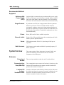
Power Input
Module
The power input modules contain the on/off switch and fuses.
Communications
Ports(SB9-PIN)
The communications port connects the Luminex 100 analyzer or the
Luminex XYP instrument to the computer, and the Luminex SD
system to the Luminex 100 analyzer.
Luminex 100
Analyzer
Ventilation Filter
Located on the bottom of the Luminex 100 analyzer, the filter must
be checked and cleaned as necessary. For proper ventilation, do not
obstruct the area below and allow at least two inches (5 cm) of
clearance around the Luminex 100 analyzer.
PN 89-00002-00-071 Rev. C
3-7
xMAP Technology
Luminex 100 IS User Manual Version 2.3
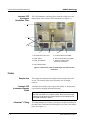
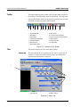
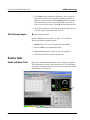
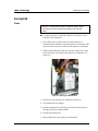
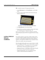
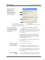
Luminex XYP
Instrument
Ventilation Filter
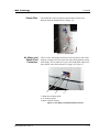
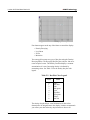
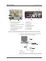
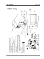
The XYP instrument ventilation filter cleans the air that cools the
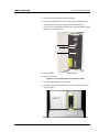
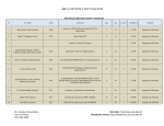
internal parts of the Luminex XYP instrument. See Figure 3-1.
1
2
3
4
5
6
7
1
1. Air intake filter access door
5. Communication Ports (DB9)
2. Power Switch
6. XYP Communication Port (DB9)
3. Power Input Module
7. Analyzer ventilation filter
(on bottom of analyzer)
4. XYP Ventilation Filter
Figure 3-1 Back of the Luminex 100 Analyzer and Luminex XYP
Instrument
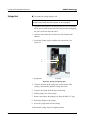
Fluidics
Sample Arm
Luminex XYP
Instrument Sample
Probe
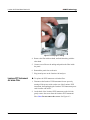
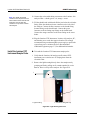
The sample arm transports the sample from the sample tube to the
cuvette. The carriage drops to the microtiter well for sample
retrieval.
A stainless steel sample probe acquires the sample. A shorter probe
is provided for shipping and troubleshooting.
Warning: During operation, this system contains exposed moving
parts that can result in a puncture hazard. Risk of personal injury
is present. Keep hands and fingers away from the sample probe.
The shield should be in place.
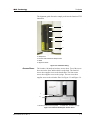
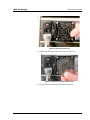
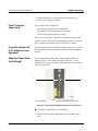
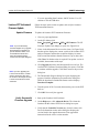
Cheminert® Fitting
3-8
This fitting attaches the Luminex 100 analyzer sample arm tubing to
the sample arm. Disconnect this fitting when you remove the sample
probe. See Figure 3-2.
PN 89-00002-00-071 Rev. C
xMAP Technology
The System
The alignment guide directs the sample probe into the Luminex XYP
instrument.
1
2
3
4
5
1. Cheminert Fitting
2. Sample Arm
3. Luminex XYP Instrument Sample Probe
4. Shield
5. Alignment Guide
Figure 3-2 Cheminert Fitting
Access Doors
The Luminex 100 analyzer has three access doors. Two of the access
doors are on the front, and the third is on the back. The front left
access door supplies access to the sheath filter. The front center
access door supplies access to the syringe. The rear access door
supplies access to the air intake filter. See Figure 3-3 and Figure 3-4.
1
2
1. Left door, access to service panel 2. Center door, access to syringe
Figure 3-3 Luminex 100 Analyzer Access Doors
PN 89-00002-00-071 Rev. C
3-9
xMAP Technology
Luminex 100 IS User Manual Version 2.3
Air Intake Filter
A replaceable air intake filter cleans the air used to pressurize sheath
fluid. This filter is enclosed behind an access door located on the
back of the Luminex 100 analyzer. See Figure 3-4.
Figure 3-4 Air Intake Filter
Syringe
The syringe delivers a sample from the 96-well microtiter plate to the
cuvette. See Figure 3-5.
1
2
1. Syringe Seal
2. Syringe
Figure 3-5 Syringe and Syringe Seal
3 - 10
PN 89-00002-00-071 Rev. C
xMAP Technology
Sheath Filter
The System
The sheath filter removes particles greater than ten microns in
diameter from the sheath fluid. See Figure 3-6.
Figure 3-6 Sheath Filter
Air, Waste, and
Sheath Fluid
Connectors
The air, waste, and sheath connectors, located on the left side of the
analyzer, connect to the SD system and waste fluid containers using
clear tubing. The air connector is green, the sheath fluid connector is
blue, and the waste fluid connector is orange. See Figure 3-7.
.
1
2
3
1. Sheath fluid connector (blue)
2. Air connector (green)
3. Waste connector (orange)
Figure 3-7 Air, Waste, and Sheath Fluid Connectors
PN 89-00002-00-071 Rev. C
3 - 11
Luminex 100 IS User Manual Version 2.3
Luminex Sheath
Delivery System
Note: If you are not using the SD
system, sheath fluid levels must
be monitored manually. Check the
sheath fluid level before starting a
run or procedure.
Waste Fluid
Container
xMAP Technology
For proper operation, place the Luminex SD system at the same level
as the base of the Luminex XYP instrument. Do not put it on top of
the Luminex 100 analyzer.
Warning: If biological samples have been tested with the
system, use your standard laboratory safety practices.
The waste fluid container receives waste from the system. The waste
container should not be placed on top of the instrument.
Caution: Waste levels must be manually monitored. Do not
allow the waste container to overflow!.
Optical
xMAP Technology
Reagents
3 - 12
The optical system consists of the optical assembly and the excitation
lasers. The optical assemblies do not require manual adjustment by
the user.
The xMAP technology reagent system consists of classification
calibration microspheres, reporter calibration microspheres,
classification control microspheres, and reporter control
microspheres.
PN 89-00002-00-071 Rev. C
4
Basic Concepts
Background
Information
Fluidics
Excitation
PN 89-00002-00-071 Rev. C
xMAP technology is a versatile system that measures soluble
analytes. The Luminex 100 IS system performs simultaneous,
discrete measurements of multiple microsphere-based reactions from
a single specimen aliquot. For more conceptual information, refer to
Practical Flow Cytometry, 3rd edition, by Howard M. Shapiro, M.D.
(New York: Wiley-Liss Inc., 1995).
There are two fluidic paths in the Luminex 100 analyzer. The first
path involves a syringe-driven mechanism that controls the sample
uptake. This mechanism permits small sample uptake volumes from
small reaction volumes. The syringe-driven system transports a
specified volume of sample from a sample container to the cuvette.
The sample is injected into the cuvette at a steady rate for analysis.
Following analysis, the sample path is automatically purged with
sheath fluid by the second fluidics path. This process effectively
removes residual sample within the tubing, valves, and probe.
Approximately 160 µL of sheath fluid is dispelled into each well
following sample acquisition. The second fluidics path is driven
under positive air pressure and supplies sheath fluid to the cuvette
and sample path.
The excitation system in the Luminex 100 analyzer involves two
solid-state lasers. A reporter laser excites fluorescent molecules
bound to biological reactants at the xMAP microsphere surface, and
a classification laser excites fluorochromes embedded in the xMAP
microsphere. The lasers illuminate the xMAP microspheres as they
flow single-file through the cuvette. RP1 refers to the excitation
wavelength. CL1 and CL2 refer to the dyes embedded in the
microsphere. DD refers to the channel that discriminates against
doublets based on size.
4-1
Luminex 100 IS User Manual Version 2.3
xMAP Technology
Photodiodes and a photomultiplier tube receive fluorescent signals
from xMAP microspheres. The Luminex 100 analyzer digitizes the
waveforms and delivers the signals to a digital signal processor
(DSP). Proprietary algorithms function with the DSP to greatly
increase sensitivity.
xMAP Microspheres
The xMAP microspheres are highly uniform, polystyrene particles
that have been crosslinked during polymerization for physical and
thermal stability. Varying amounts of fluorochromes embedded
within each xMAP microsphere give each xMAP microsphere set an
unique fluorescent signal. To ensure the stability of this signal, it is
essential to protect the microspheres from light. Follow the product
information sheet instructions for storage procedures for xMAP
microspheres and assay kits.
Calibrator xMAP microspheres are used to normalize the settings for
the reporter channel, both classification channels and the doublet
discriminator channel for the Luminex 100 analyzer.
The control xMAP microspheres are used to verify the calibration
and optical integrity of the system.
Software Overview
This section provides a brief overview for using the Luminex 100 IS
2.3 software.
With the Luminex 100 IS 2.3 software, you work with assay kits
provided by a kit manufacturer. A template may be included with
each kit that is imported into the software. The template includes a
sequence of commands required for the assay.
Once you select the template, you enter sample data into a “batch.”
Sample input can be done quickly with either the keyboard or a
barcode scanner. A batch can include as many samples as you have
for the assay and can include multiple microtiter plates. You can even
group multiple batches together into a multi-batch for efficient
processing. You can process a batch immediately or choose to
archive the batch for testing later.
As testing proceeds through the plate, you will see the display update
to show the wells that have been processed. Progress is shown in
both graphic and tabular form.
4-2
PN 89-00002-00-071 Rev. C
xMAP Technology
Basic Concepts
System calibrators and controls are provided as part of the system.
Calibrate at least once monthly, when the delta calibration (dCAL)
temperature changes by ±3 degrees, or if the system is powered off
or moved. You must run system controls following calibration and as
often as you like to ensure that your system continues to operate
optimally.
The software provides you with a variety of reports.
•
•
•
•
•
•
•
•
Analyte Reports provide batch results grouped by the test in a
batch.
Patient Summary reports provide batch results grouped by each
patient or unknown in a batch.
Clinical Patient reports provide a breakdown of samples
according to the test analysis with that sample.
Maintenance Reports provide a history of all maintenance
operations performed during a specified period of time.
Calibration Trend reports provide results of calibration
commands performed over a specified time period.
System Control Trend Reports provide results of system controls
performed over a specified time period.
Batch Summary Reports provide batch information in a sample
versus test grid format.
Quality Control Reports track the trends of assay controls over a
period of time
These reports let you look at specific details regarding the samples
you process through the Luminex 100 IS 2.3 software and system
operation.
System tools help you monitor the system including a display
showing real-time system property values and a message log. Errors
are shown in the message log and also on your reports. You can even
add comments to specific results in some of these reports.
To keep track of your reagents, the Luminex 100 IS 2.3 software
stores lot numbers, expected values, and expiration information.
A comprehensive set of self-diagnostic tests ensure that your system
is working correctly. These tests are performed at startup and can be
performed at any time. If any problem is detected, an error message
appears in the message log to inform you.
PN 89-00002-00-071 Rev. C
4-3
Luminex 100 IS User Manual Version 2.3
4-4
xMAP Technology
PN 89-00002-00-071 Rev. C
5
Using Luminex 100 IS 2.3 Software
This manual describes how to use the Luminex IS 2.3 software. It
includes a glossary and information regarding the CSV file setup.
The software user should have a basic familiarity with computers and
Microsoft® Windows®. Commands are often available through
more than one method, such as from the main menu bar, the toolbar,
or on different windows. However, each procedure in this manual
will describe only one method of accessing commands.
This chapter has the following sections:
•
•
•
•
Main Window - This section describes the main window of the
Luminex IS 2.3 software, including tabs and commands. Use this
section to become familiar with the main functions of the
software.
Secondary Windows - This section describes the secondary
windows in the Luminex IS 2.3 software, including the Analysis
Window and Batch Setup Window.
Commands - This section describes the functions of the
commands in the Luminex IS 2.3 software.
Procedures - This section describes how to perform tasks using
the Luminex IS 2.3 software.
When using microtiter plates, use plates with wells that will hold at
least 185 µL (the extra 25 µL from the sample, plus an extra 160 µL
that is dispensed back into the well following acquisition).
Main Window
The Luminex IS 2.3 software starts automatically when you log into
Windows.
When the first software User window opens, the Main window is
open, with the Home tab displayed, as shown in Figure 5-1
PN 89-00002-00-071 Rev. C
5-1
xMAP Technology
Luminex 100 IS User Manual Version 2.3
.
1
2
3
4
5
1. Title bar
2. Menu bar
3. Tool bar
4. Tabs
5. Status bar
Figure 5-1. Luminex IS 2.3 Main Window
There are five major parts in the Main window: Title bar, Menu bar,
Tool bar, Tabs, and Status bar. A brief description of each of these
components is shown below.
The Title Bar displays the name of the software.
The Menu Bar contains three menus, File, Tools, and Help menu. A
more thorough description of the Menu is shown on page 5-3.
The Toolbar - has shortcut buttons for frequently-used commands. A
more thorough description of the Toolbar is shown on page 5-4.
There are five Tabs, organized by function. The tab that displays
when the software starts up is the Home tab. A more thorough
description of each of these tabs begins on page 5-4.
The Status bar displays the system status at the bottom of the main
window. A more thorough description of the Status bar is shown on
page 5-17.
5-2
PN 89-00002-00-071 Rev. C
xMAP Technology
Menu Bar
Using Luminex 100 IS 2.3 Software
The menu bar contains the following menus: File Menu, Tools Menu,
and Help Menu.
File menu - contains the following commands:
•
•
•
•
•
•
•
•
•
•
•
•
•
Import Template
New Batch
Open Batch
Delete Batch
Edit Patient List
Open Incomplete Batch
Batch Comment
New Multi-Batch
Open Multi-Batch
Data Analysis
Export Batch Data
Print Report
Exit
Tools menu - contains the following commands:
•
•
•
•
•
•
•
•
•
•
Connect
Disconnect
Database Backup
Database Restore
Erase Database
Update CAL Targets
Update CON Targets
New Assay Lot
Options
Cleanup
For information on each of these commands, see the Commands
section, beginning on page 5-31.
Help menu - this contains menu selections that open the online help
and describe the software and hardware.
• Contents opens the online help
• About the Device opens a dialog box that shows the version
and serial numbers of the Luminex instruments you are using.
• About the Software opens a dialog box that shows the
version of the Luminex Software you are using.
PN 89-00002-00-071 Rev. C
5-3
xMAP Technology
Luminex 100 IS User Manual Version 2.3
Toolbar
The shortcut buttons on the toolbar can be found in other locations in
the software. The Help button opens the online help. The Single Step
option on the toolbar allows you to pause the system in between each
command or sample acquisition within a batch.
1
2
3
4
5
6
7
8
9
10 11
12
13
1. Import Template
8. Print Report
2. New Batch
9. Connect to the Instrument
3. Open Batch
10. Disconnect from the Instrument
4. Create New Multi-Batch
11. Eject/Retract
5. Open Multi-Batch
12. Open Help File
6. Start Analysis
13. Single Step
7. Export Batch Data
Figure 5-2. Luminex IS 2.3 Toolbar
Tabs
This section describes the tabs in the Main window.
Home tab
This is the default tab. It is organized by the order of system use. It
contains a Favorites list and five button groups representing data
acquisition and maintenance categories.
1
2
1. Favorites List
2. Button Groups
Figure 5-3. Home Tab
5-4
PN 89-00002-00-071 Rev. C
xMAP Technology
Using Luminex 100 IS 2.3 Software
Favorites. You can use the Favorites list to create a customized list
of often-used commands and templates. Items appear in alphabetical
order for easy locating. For more information on setting up the
Favorites list, see page 5-42.
Button Groups. Button groups are grouped according to function.
• The Daily Startup group contains the Warmup, Prime,
Alcohol Flush, and Wash Commands. For more information
on daily startup, see page 5-43. For more information on the
commands, see the Commands section on page 5-31.
• The Instrument Calibration group contains the CAL1,
CAL2, CON1, and CON2 buttons. For more information on
calibrating the system, see page 5-46. For more information
about these commands, see the Commands section on page 531.
• The Batch Setup group contains the New Batch, New
Multibatch, and New Lot buttons. For more information on
creating and running batches and multibatches, see page 5-51.
For more information about these commands, see the
Commands section on page 5-31.
• The Reports and Analysis group contains the Analysis and
Print buttons. For more information on running reports and
analyses, see page 5-86. For more information about the
Analyses and Print commands, see the Commands section on
page 5-31.
• The Daily Shutdown group contains command buttons that
you can use when shutting down the system. For more
information on performing a daily shutdown, see page 5-96.
For more information on the Sanitize and Soak commands, see
the Commands section starting on page 5-31.
Run Batch Tab
PN 89-00002-00-071 Rev. C
The Run Batch tab contains a microtiter plate and reservoir image,
XYP and DD temperature readbacks, a sheath pressure gauge, print
button, command list displaying batch commands and their status,
and plate and XYP command buttons. See Figure 5-4.
5-5
xMAP Technology
Luminex 100 IS User Manual Version 2.3
1
2
3
1. Microtiter plate/reservoir image 2. Temperature and Pressure Gauges
3. Command List
Figure 5-4. Run Batch Tab
The command buttons on the Run Batch tab are:
•
Print Worklist
•
Eject/Retract
•
Start Plate
•
Resume
•
Cancel Command
•
Pause
•
Cancel all
For more information on these commands, see the Commands
section, starting on page 5-31. For more information on setting up
batches, see See “Batch Setup Procedures” on page 51.
The microtiter plate and reservoir image represents where you
place samples or other fluids used in running or maintaining the
system. Samples are analyzed vertically, from top to bottom within
the column, and then from left to right for subsequent columns.
The Temperature and Pressure Gauges show information about the
analyzer and the XYP instrument. The XYP heater temperature
measures the internal Luminex XYP instrument plate temperature.
5-6
PN 89-00002-00-071 Rev. C
xMAP Technology
Using Luminex 100 IS 2.3 Software
The DD temperature measures the doublet discriminator temperature.
DD temperature shifting indicates a need for system recalibration. If
you have not calibrated, the arrows showing the temperature range
for the DD temperature both appear at the bottom of the
thermometer, and the thermometer appears in red. An out-of-range
temperature logs an error, but does not halt the acquisition.
For information on setting the XYP instrument heater temperature,
see page 5-45.
The Command List displays commands associated with batches,
new advanced batches or multi-batches loaded for processing on the
system. The Command List shows the status of each command as the
system processes it, and whether the command completes
successfully or fails. Figure 5-5 shows that the first two commands
were successful, the third command is running, and the rest of the
commands are pending. Figure 5-6 shows that the third command
failed.
Figure 5-5. Command List Section of the Run Batch Tab
Figure 5-6. Command Failure Notation in the Command List
Errors are recorded in the Message Log on the Diagnostics tab. See
page 5-9 for more information about the Diagnostics tab. Doubleclick on failed commands in the Message Log for additional
information. You can right-click a highlighted row to copy data to the
clipboard or clear the batch from the screen.
PN 89-00002-00-071 Rev. C
5-7
xMAP Technology
Luminex 100 IS User Manual Version 2.3
Maintenance Tab
Use the Maintenance tab to perform maintenance, XYP, daily startup,
calibration, and verification commands to maintain your system and
keep it in optimal working order.
Figure 5-7. Maintenance Tab
See the Commands section starting on page 5-31 for detailed
information about these commands:
•
•
•
•
•
•
•
•
•
•
Warmup
Prime
Backflush
Alcohol Flush
Sanitize
Wash
Drain
Soak
Self Diagnostics
Calibration Commands: CAL 1, CAL2, CON 1, CON2, New
CAL target and New CON target
• Sample Probe Down
• Eject/Retract
5-8
PN 89-00002-00-071 Rev. C
xMAP Technology
Using Luminex 100 IS 2.3 Software
Instructions for maintenance procedures begin on page 5-92. Table 511 on page 5-92 shows a recommended use schedule for maintenance
operations.
Diagnostics tab
Use the Diagnostics tab to monitor the progress of commands you
initiate in the system. Features on this tab monitor the state of system
components. This tab displays the System Monitor, Detailed Sample
Progress chart, and Message Log. The Text on the Diagnostics tab
turns red if the system encounters an error. The Message Log on the
Diagnostics tab indicates where the error occurred.
Figure 5-8. Diagnostics Tab
Use these tools to find information about the system and what occurs
during sample acquisition and other functions. For example, you may
look on the Message Log to see the last completed command or the
one currently in progress.
The System Monitor provides information about the physical state
of the Luminex analyzer including lasers and system calibration
status. The values displayed are reported directly from the Luminex
analyzer and the Luminex XYP instrument. It shows whether the
calibration or control results completed successfully by displaying
green text for successful events and red text for failed events.
PN 89-00002-00-071 Rev. C
5-9
xMAP Technology
Luminex 100 IS User Manual Version 2.3
The system diagnoses real-time system problems related to fluidics
and optics. The system also detects and reports if the Luminex XYP
heater block temperature is out of range or experiencing
unacceptable temperature conditions, including these items:
•
•
•
•
Luminex XYP heater block temperature time-out
heat circuit failure
temperature out-of-range sensing
temperature change since calibration, or a change in channel
temperature
Table 5-1 defines the values listed in the System Monitor. These
values are useful for diagnostic purposes when communicating with
Luminex Technical Support.
Table 5-1. System Monitor Values
Property
5 - 10
Value Units of Measure
Air Pressure
PSI, air pressure to the sheath
container from the air pump
Sheath Pressure
PSI, sheath pressure from the
sheath container through the
system
Delta Cal Temperature
°C, temperature deviation from
the last calibration
Board Temperature
°C, temperature of the analog
board
DD Temperature
°C, DD temperature at the U
block inside the optics platform
CL1 Temperature
°C, CL1 temperature at the U
block inside the optics platform
CL2 Temperature
°C, CL2 temperature at the U
block inside the optics platform
XYP Board Temperature
°C, temperature of the XYP
board inside the Luminex XYP
instrument
XYP Heater Temperature
°C, temperature of the XYP
heaters inside the Luminex
XYP instrument
PN 89-00002-00-071 Rev. C
xMAP Technology
Using Luminex 100 IS 2.3 Software
Table 5-1. System Monitor Values (Continued)
Property
XYP Heater Temperature In
Range
Value Units of Measure
Indicates if the XYP heater is in
the set range
The Detailed Sample Progress section displays the percentage of
completion for each bead ID or test. The graph shows real-time
progress, so that as each sample is analyzed, the graph adjusts to
show progress. Use the zoom button to view up to 20 tests at a time.
Use the toggle button to view the bead ID or test name. Use the
Expand Margin (up/down and left/right) arrows to expand the chart
margins and view longer test names. See Figure 5-9.
.
1
2
3
1. Zoom button
2. Toggle button
3. Expand Margin arrows
Figure 5-9. Detailed Sample Progress
The Message Log is the lower pane on the Diagnostic tab. It displays
a list of completed commands, errors, and warnings. It also displays
command progress, time and date, and results. See Figure 5-10.
PN 89-00002-00-071 Rev. C
5 - 11
xMAP Technology
Luminex 100 IS User Manual Version 2.3
Figure 5-10. Message Log
The log displays actions in color-coded text and shading. Items in the
Message Log appear in the following color codes:
•
•
•
•
Green text represents a successful system calibration,
verification command, acquisition, or maintenance functions.
Red text represents failed commands, errors, or warnings.
Black text represents normal processes and actions.
Yellow shading indicates that a detailed description about the
processes or actions is available. This color may vary depending
on your tool tip color system settings.
To view details of a message, double-click the shaded row. A
dialog box opens providing details. To clear the Message log,
right-click in the Message Log area, and click Clear on the menu.
Acquisition Detail
Tab
The Acquisition Detail tab offers advanced batch sample monitoring
and “on the fly” data acquisition without templates. The primary
function is real-time monitoring of batch sampling during acquisition
through a display of sample bead statistics, histogram, and dot plot
data.
During batch acquisition, bead statistics can be useful if batch errors
occur. For example, if samples are constantly failing due to
insufficient bead count, you can monitor whether the failure is due to
low bead concentration or if other assay problems are present.
The Acquisition Detail tab provides access to the Developer
Workbench (DWB) software features. Details about these features
are provided in the Luminex Developer Workbench Guide Version 2.3
documentation. You must have the DWB software installed to enable
these features.
Caution: Do not alter kit manufacturer’s predefined templates or
create alternative templates for off the shelf kits unless instructed
by the kit manufacturer.
5 - 12
PN 89-00002-00-071 Rev. C
xMAP Technology
Using Luminex 100 IS 2.3 Software
Acquisition Detail tab features:
•
•
•
•
•
Batch Name and Description
Batch Data Area
Acquisition Detail Toolbar
Histogram
Dot Plot
Figure 5-11 identifies the major features of the Acquisition Detail
tab.
2
1
5
4
3
7
6
1. Luminex IS 2.3 Toolbar
5. Status Bar
2. Batch Name and Description
6. Histogram
3. Batch Data Area
7. Dot Plot
4. Acquisition Detail Toolbar
Figure 5-11. Acquisition Detail Tab
PN 89-00002-00-071 Rev. C
5 - 13
xMAP Technology
Luminex 100 IS User Manual Version 2.3
The Batch Name and Description section displays the name of the
batch as well as its description.
The Batch Data area displays sample results. The left column shows
plate location and Sample ID description. The remaining columns
display selected bead sets for the assay. Each row represents the data
for each bead set from one well.
The Acquisition Detail Toolbar shown in Figure 5-12 provides
functions to acquire raw data without using templates. The toolbar
has additional buttons if you have Developer’s Workbench installed.
For more information about the commands on the Acquisition Detail
Toolbar, see the Command section, beginning on page 5-31.
1
2
3
4
5
6
7
8
1. Replay Batch
6. Cancel All
2. New Advanced Batch
7. Eject/Retract
3. View Batch Data
8. Pause
4. Start Plate
9. Resume
9
5. Cancel Command
Figure 5-12. Acquisition Detail Toolbar
The Histogram, in the lower left section of the Acquisition Detail
tab, defaults to display the Doublet Discriminator (DD) on the X axis
and Events on the Y axis. Doublets appear when two microspheres
stick together, creating undesired results. When you enable the gate,
two vertical red, dashed lines appear to represent gate positions
determined by the template or settings established within the New
Advanced Batch. After setting the gate, everything outside the gate is
ignored. You cannot change the gate position during batch
acquisition. You can change the gate positions before data
acquisition, after the system finishes acquiring data, or after pausing
the system. The change is visual. The data is still collected according
to the gate positions set in the assay template or New Advanced
Batch setup. The gate in effect when the system collects data
determines which values to use to obtain the result. Applying a gate
or changing a gate for existing data does not change your calculated
values. The gate positions, also located in the lower corner of the
histogram, are used while collecting data are the numerical values
selected in the template or the New Advanced Batch.
5 - 14
PN 89-00002-00-071 Rev. C
xMAP Technology
Using Luminex 100 IS 2.3 Software
1
2
3
1. Gate Boundaries 2. Aggregate Beads 3. Numerical Gate Position
Figure 5-13. Set DD Gate Example
The Histogram contains the Show Bead menu and four buttons:
•
•
•
•
Autoscale
Zoom
Log/Linear
Maximize
For more information on these commands, see the Commands
section beginning on page 5-31.
The Dot Plot (or bead map) appears in the lower-right section of the
Acquisition Detail tab. See Figure 5-14. The dot plot shows a
graphical display of real-time data collection.
Luminex recommends using the default settings to collect data. The
default axes are Classification 1 on the X axis and Classification 2 on
the Y axis. To see the dot plot, you must use the default axis. To
display the bead set information, hover the mouse pointer over the
desired region. You can change the X axis and Y axis of the dot plot
for troubleshooting purposes, although you should use the default
settings in all other scenarios.
PN 89-00002-00-071 Rev. C
5 - 15
xMAP Technology
Luminex 100 IS User Manual Version 2.3
Figure 5-14. Dot Plot Display Example
Four buttons appear at the top of the frame to control the display:
•
•
•
•
Density/Decaying
Log/Linear
Zoom
Maximize
You can toggle between two types of dot plots using the Density/
Decaying button. The Decaying Dot Plot plots only the 100 mostrecent acquired events. The Density Dot Plot displays a constant
accumulation of events. Increasing density is indicated by
contrasting colors. See Table 5-2 for the density dot plot color
legend.
Table 5-2. Dot Plot Color Legend
Layer
0
1
2
3
4
5
6
7
8
Color
none
dark blue
pink
dark green
cyan
light blue
light green
orange
dark red
The density dot plot allows visual elimination of data values
determined to be insignificant to the display. Luminex recommends
you collect your data in density dot plot mode to observe all
5 - 16
PN 89-00002-00-071 Rev. C
xMAP Technology
Using Luminex 100 IS 2.3 Software
collected events. Post acquisition does not display decaying dot plot;
it’s only a real-time function.
Status Bar
The Status Bar displays information about the Command State,
Device Status, Device Activity, Laser Status, Total Events per
Second, and Region Events per Second. Color coding indicates the
urgency of each item’s status. Device Activity uses no color coding.
Figure 5-15. System Status Bar
Table 5-3 describes the types of status bar messages in relation to the
message color coding.
Table 5-3. Status Bar Color Coding
Category
Command
State
Device Status
Device
Activity
PN 89-00002-00-071 Rev. C
Color
Indicates
Indicates communication status of the Luminex analyzer or
operations being processed
Green
Idle or processing
Yellow
Connecting, pausing, or paused
Red
Disconnected or locked out
Indicates the current process of or warning about the
Luminex analyzer
Green
Running or standby
Yellow
Busy, pressurizing, sheath is empty, or warming
up
Red
Not ready or disconnected
Indicates the activity that the Luminex analyzer is
performing. Note: The device activity has no color code.
5 - 17
xMAP Technology
Luminex 100 IS User Manual Version 2.3
Table 5-3. Status Bar Color Coding (Continued)
Category
Color
Indicates
•
•
•
•
•
•
•
•
•
•
•
•
•
•
•
Laser Status
Idling: waiting for a command
Aspirating: drawing in sample
Collecting Data: collecting data
Sanitizing: sanitizing the instrument
Washing: washing the sample line
Priming: priming the instrument
Calibrating: calibrating the instrument
Canceling: canceling a command
Backflushing: backflushing the instrument
Draining: draining the instrument
Warming Up: warming up the instrument
Verifying: verifying calibration
Soaking: soaking the probe
Adjusting sample probe
Self Diagnosing: performing self-diagnostic
routine
Laser temperature and readiness status
Green
Lasers warmed up
Yellow
Warmup timer countdown in seconds from 1800
Red
Lasers off
Total Events/
Second
Number of total bead events detected per second
Region
Events/Second
Number of bead events detected per second that are
classified in a region
The Status Bar displays status information as the software processes
commands. Table 5-4 shows the typical messages that appear in the
status bar. Additionally, information displays as text on the
Diagnostics tab.
5 - 18
PN 89-00002-00-071 Rev. C
xMAP Technology
Using Luminex 100 IS 2.3 Software
Table 5-4. Status Bar
Communication Message Details
Status Bar
Color
Green
Yellow
Red
PN 89-00002-00-071 Rev. C
Message
Indicates
Idle
Waiting to process the next
command.
Standby
The Luminex analyzer is ready
and waiting to perform a
command.
Connecting
The software is attempting to
connect to the instrument.
Processing
The instrument is communicating
with the software as it processes
commands.
Pausing
The instrument has stopped
processing the list of commands,
but finishing the active command.
Paused
The software stopped processing
the list of commands. A “resume”
function becomes available to
change the state back to
“processing.”
Busy
The instrument is processing a
maintenance command.
Disconnected
The software has not yet
attempted to connect or fails to
connect to the instrument.
Locked Out
Another application currently has
control of the instrument. The
software locks out as long as the
other application runs. To remove
the locked out status, close the
other application or wait until the
application completes.
5 - 19
xMAP Technology
Luminex 100 IS User Manual Version 2.3
Secondary
Windows
Batch Setup Window
In addition to the main window, there are other windows that are
displayed when you select certain commands. These are the Batch
Setup Window and Analysis Window. Additional windows display in
the Developer’s Workbench software, if you have it installed on your
system. For more information about the Developer’s Workbench, see
the Luminex Developer Workbench Guide for Version 2.3.
In the Batch Setup window, you define information used to create
batches. All of the commands are on the same page; there are no
tabs. The window opens when you click New Batch and select a
template.
The following features are part of the Batch Setup Window:
•
•
•
•
5 - 20
Batch Info group box
Template Info group box
Insert command
Command list
PN 89-00002-00-071 Rev. C
xMAP Technology
Using Luminex 100 IS 2.3 Software
•
•
•
•
•
•
Microtiter Plate image
Command button group box
Save group box
Standard Info group box
Control Info group box
New Lot button
The Batch Info group box has text boxes in which you can input the
name, description, and creator name of a new batch.
The Template Info group box shows the name, description, version
number, and developing company for the template that you are using
in a batch.
The Insert command lets you insert a patient into a batch or skip a
well.
The Command list displays the commands that were imported from
the template, plus commands added using the Insert command or
manually entered. The lock in the far left column indicates that the
command was imported from the template and cannot be changed in
the Batch Setup window.
The Microtiter Plate image reflects the command information for
each well, as defined in the template.
The Command button group contains the Finish, Cancel, Load Pa
List, and Help command buttons. For more information on these
commands, see the Commands section, beginning on page 5-31.
The Save group box contains the Save and Load and Save only
option buttons. For more information on these commands, see the
Commands section, beginning on page 5-31.
The Standard Info group box is visible only if the template you are
using requires the use of standards. If standards are used in the
template, the Standard Info group box reflects the Standard
information as defined in the template product.
The Control Info group box is visible only if the template you are
using requires the use of controls. If controls are used in the
template, the Control Info group box reflects the Control information
as defined in the template products.
PN 89-00002-00-071 Rev. C
5 - 21
xMAP Technology
Luminex 100 IS User Manual Version 2.3
The New Lot button is visible only if the template you are using
requires the use of standards or controls. The button opens the
Update Lot Information dialog box, in which you can manage lot
information.
Analysis Window
When the system analyzes batches, it displays the data in a three-tab
format within the Analysis window. The following three tabs present
the batch information in greater detail:
•
•
•
Errors tab—lists errors that occur during batch acquisition, such
as controls that failed.
Standards tab—lists all tests in the batch, a regression chart for
each test, and the standards or controls associated with the batch.
Samples tab—lists background samples and all samples or
unknowns acquired in the batch with either a qualitative or
quantitative result.
Nine function buttons are available on the lower portion of the
Analysis window. These buttons perform tasks or functions that are
relevant to the Standards tab although they appear on all three tabs of
the Analysis window. The buttons are:
•
•
•
•
•
•
•
•
•
Next Test (F2)
Previous Test (F3)
Invalidate Standard (F4)
Validate Standard (F5)
Invalidate Control (F6)
Validate Control (F7)
Change Standard - only if Developer’s Workbench is installed.
Change Lot (Alt + F8)
Recalc (Standards tab only) - only available on the Standards tab,
and only if the Auto checkbox is not selected.
For a description of these commands, see “Commands” on page 531. For information on procedures using these commands, see
“Validating or Invalidating Standards and Controls” on page 5-83
and “Change Lot” on page 5-85.
In addition to the function buttons, you can choose to sort data
sequentially by order acquired, or alphabetically by Sample ID.
These options are available in the Sort group box next to the function
buttons. These sorting functions are helpful in viewing batches
containing replicate samples. Replicate samples are defined as
samples with identical sample identifications. Replicate standards,
5 - 22
PN 89-00002-00-071 Rev. C
xMAP Technology
Using Luminex 100 IS 2.3 Software
controls, and unknown samples are not always acquired in sequential
wells and thus make sample viewing difficult. When viewing
samples alphabetically all replicate samples are displayed together
with the replicate sample’s average (AVG), then individual samples.
If you view replicate batches sequentially, each sample displays in
the order it was acquired, followed by a replicate average summary
section.
Errors Tab
The Errors tab displays a list of errors that occurred during
acquisition. It organizes the errors in two categories: System and
assay errors (top section of tab), and Sample errors (bottom section
of tab) Table 5-5 lists the errors in each category
Figure 5-16. Analysis Window - Errors Tab Open
PN 89-00002-00-071 Rev. C
5 - 23
xMAP Technology
Luminex 100 IS User Manual Version 2.3
Table 5-5. Error Categories
System and Assay Errors
•
•
•
•
•
•
•
•
•
•
•
•
•
•
•
Standards Tab
Instrument Not Calibrated
Failed Verification (system lists
each failed control)
Failed Control (verifier failed)
Temperature Divergence from
Calibration Temperature
Failed Curve Fit
Analysis Error
APD Temp Range Exceeded
XYP Temp Unstable
Low Voltage
High Sheath Pressure
Low Sheath Pressure
Command Timeout
Low Laser Power
Cannot Calculate Inverse
Function
Failed Std in Batch
Sample Errors
•
•
•
•
•
•
•
•
•
Insufficient Bead Count
Sample High/Low
Analyzer Error
High Sheath Pressure
Low Sheath Pressure
Sample Timeout
Sample Empty
Cannot Calculate Inverse
Function
Different Qualitative Results
The Standards tab lists all the batch tests with system comments
specific to each test. The detailed test information that is displayed
on the three tabs of the Analysis window is determined by the test
selected under the Standards tab.
The Standards tab displays the quantitative batch’s standard curve. It
displays qualitative batches as a graph plotting the assay standard.
Above the graphical information, the tab displays the formula that it
used to calculate batch data. Below the graphical information, the tab
displays the Standards and Controls values for the selected test.
5 - 24
PN 89-00002-00-071 Rev. C
xMAP Technology
Using Luminex 100 IS 2.3 Software
Figure 5-17. Analysis Window - Standards Tab Open
When a median fluorescence intensity (MFI) value for an unknown
sample or control lies outside the standard curve MFI range, the
concentration is not calculated. The unknown sample or control
result is reported as less than (<) or greater than (>) next to the
corresponding standard expected concentration. The out-of-range
samples and controls will also have a “Sample High/Low” statement
in the comment column. If a sample lies within the standard curve
MFI range, but the sample’s MFI value does not intersect the curve,
the result will be reported as “Error”. A “cannot calculate inverse
function” statement displays in the comments column. This error
condition usually occurs when a standard curve “flattens out” at the
high or low end. Examples of out-of-range sample labeling for noncompetitive assays are shown in Table 5-6. Figure 5-18 shows what
a standard curve for a non-competitive assay should look like.
PN 89-00002-00-071 Rev. C
5 - 25
xMAP Technology
Luminex 100 IS User Manual Version 2.3
Table 5-6. Non-Competitive Out-Of-Range Labeling
Condition
Concentration Label
MFI of Standard Referenced
Left of Curve
< min concentration standard
Lowest
Right of Curve
> max concentration standard
Highest
Figure 5-18. Non-Competitive Assay
Examples of out-of-range sample labeling for competitive assays are
shown in Table 5-7. Figure 5-19 shows what a standard curve for a
competitive assay should look like.
Table 5-7. Competitive Out-Of-Range Labeling
5 - 26
Condition
Concentration Label
MFI of Standard Referenced
Left of Curve
< min concentration standard
Highest
Right of Curve
> max concentration standard
Lowest
PN 89-00002-00-071 Rev. C
xMAP Technology
Using Luminex 100 IS 2.3 Software
Figure 5-19. Competitive Assay
The standards tab displays an Expected Concentration column for
standard and control samples. The Standards Expected Concentration
column allows users to edit the standard concentrations. You can edit
controls; however, you must select the control name or Expected
Concentration box for that control, then click Change Lot.
When editing standard and control lot values the system may prompt
you for a new number. If this is the first batch you analyze using this
lot number, the system allows editing without requiring a new lot
name. However, if you have analyzed a previous batch using this lot,
the system will require that you rename the lot if edited or modified.
Background samples are commonly used in the assay process.
Although recommended, the discretion on whether to use or not is
left to the assay or kit developer. If background samples are included
they are defined in the assay template.
Background samples are samples with no active test substance. The
system uses background samples to remove assay background noise
from the sample results. Typical background samples contain
coupled beads, assay buffer, detection reagents, and reporter
fluorophore. Background samples do not contain target analytes.
If the background sample is designated accordingly, the system
subtracts the background sample’s reported fluorescence from all
other samples in a batch to report net MFI. If a batch contains more
PN 89-00002-00-071 Rev. C
5 - 27
Luminex 100 IS User Manual Version 2.3
xMAP Technology
than one background sample, the fluorescence values of the two
background samples are averaged together and subtracted from the
other samples to obtain a net fluorescence intensity.
Samples Tab
The Samples tab lists tests from your batch and displays the results
for each sample.
Figure 5-20 shows a Sample tab example listing three tests. Notice
that the left pane displays Test IL-4, IL-6 and IL-8 with Test IL-4
selected. The right pane shows the IL-4 sample results. Notice that
the well G3 location test result is “<10” and the associated
Comments column for the third sample indicates a sample out of
range error “Sample High/Low” because this sample has an MFI less
than the lowest standard in the standard curve for this noncompetitive batch.
The first sample is within the standard curve range and thus displays
an unflagged test result.
The system does not flag results as normal or abnormal according to
a defined range. Error flags only note samples that fall below or
above the standard curve.
The Comments column cells are editable and the information is
displayed in reports.
5 - 28
PN 89-00002-00-071 Rev. C
xMAP Technology
Using Luminex 100 IS 2.3 Software
Figure 5-20. Analysis Window - Samples Tab Open
Replicate
Averaging
Standard and control replicates are predefined in the template. You
define unknown sample replicates in batch setup indicated by
replicate Sample ID.
The data analysis function supports replicate sampling. It calculates
each sample as an individual sample, which is then averaged to
obtain a replicate average.
• Standards tab—displays standard and control average values.
• Samples tab—displays sample average values.
Replicate averages are displayed with AVG in the Loc (location)
column.
The AVG entry appears immediately after the wells being averaged
or at the end of the list depending on what you select under Sort
(Sequentially or Alphabetically).
PN 89-00002-00-071 Rev. C
5 - 29
Luminex 100 IS User Manual Version 2.3
xMAP Technology
If the system fails to determine the results for a replicate due to an
excessive skew of one of the samples, you can invalidate the out of
tolerance value. Use the Invalidate Standard (F4) or Invalidate
Control (F6) buttons at the bottom of the Analysis window. Be
aware that this fixes standards and controls, not patient sample. If
any of the replicate standards and/or controls are invalidated, the
“Avg” results reflects the average of the remaining standard and/or
control replicates.
The system flags the failed sample so you may calculate the replicate
set’s average without including the failed result in the equation.
You can sort the batch samples Sequentially (by the order in which
they are acquired), or Alphabetically (by sample ID). Select the
sorting method in the Sort group box.
5 - 30
PN 89-00002-00-071 Rev. C
xMAP Technology
Commands
Acquire Patient
Add Batch
Alcohol Flush
Autoscale
Autosize
Backflush
Using Luminex 100 IS 2.3 Software
This section describes the different commands used in the Luminex
IS 2.3 software. They are grouped Alphabetically
This command, which is part of the Insert command/menu, adds
patients to the command list. After adding the patients you define the
Sample ID and Dilution Factor for each new patient. The Dilution
Factor defaults to 1.
When creating a multibatch, adds an existing batch to a multi-batch.
Removes air bubbles from the sample tubing and the cuvette using
70% isopropanol or 70% ethanol. The alcohol flush takes about five
minutes. Uses the Luminex XYP reservoir due to volume
requirement.
Automatically adjusts the maximum number of events shown on the
Y axis on the histogram. Click during acquisition to readjust the Y
axis scale.
Automatically adjusts column widths to fit the data and header sizes.
Removes obstructions from the fluidics pathways by drawing sheath
fluid from the sheath fluid container. You do not need to supply
solution in a plate. A backflush command takes about seven seconds.
CAL1
Runs the Classification portion of the Luminex System calibration.
CAL2
Runs the Reporter portion of the Luminex System calibration.
Cancel (Command)
Cancels the process for the last command initiated.
Cancel All
Cancels all the commands in progress.
Change Lot
Opens the Change Lot dialog box from which you select a lot to
apply to a batch.
CON1
Runs the verification for the Classification calibration.
CON2
Runs the verification for the Reporter calibration.
PN 89-00002-00-071 Rev. C
5 - 31
xMAP Technology
Luminex 100 IS User Manual Version 2.3
Connect to Instrument
Create New Multi-Batch
Delete Batch
Density/Decaying
Display Confirmation
Screens
Disconnect from
the Instrument
Drain
Eject/Retract
Enable Raw Data Storage
Export Batch Data
Export CAL
Export CON
5 - 32
Establishes a connection between the PC and the analyzer.
This command opens the Luminex Multi-Batch dialog box, in which
you add or create new batches to add to a multi-batch.
Opens the Delete Batch dialog box, which shows a listing of the
unprocessed batches in the database. When you highlight a batch and
click Select in this dialog box, the system deletes the selected batch.
Toggles between the default density dot plot and the decaying dot
plot views.
Enables confirmation dialog boxes to display when you initiate many
of the maintenance commands.
Disconnects communication between the PC and the analyzer
Used during troubleshooting to help remove debris from the bottom
of the cuvette. When draining, you do not need to supply solution.
Draining takes approximately two minutes and should be followed
by an alcohol flush with 70% isopropanol or 70% ethanol. Any fluid
that drains from the system drains to the Luminex XYP reservoir as
the default. However, you can set the system to drain to any unused
well on the microtiter plate. The drain function normally expels 125
µL of fluid.
If the XYP plate is retracted, this command ejects the microtiter
plate. If the XYP plate is already ejected, this command retracts the
plate.
Saves bead event data to the database.
Opens the Open Batch dialog box, from which you choose a batch to
export to an output.csv file.
Opens a dialog box in which you choose the calibration file to export
to an output file.
Opens a dialog box in which you choose a control (validation) file to
export to an output file.
PN 89-00002-00-071 Rev. C
xMAP Technology
Export Data
Help
Import Calibration
Import Control
Import Template
Insert
Invalidate Control
Invalidate Standard
Load Patient List
Log/Linear
Maximize/Minimize
Next Test
PN 89-00002-00-071 Rev. C
Using Luminex 100 IS 2.3 Software
Exports data to a .csv file in the batch folder. There is no dialog box
to confirm that the data was exported.
Opens the help file. Use this command if you need instructions on
using a feature in the Luminex IS 2.3 software.
Opens a dialog box in which you select a calibration file that
contains calibration lot information to import to use for calibrating
the analyzer.
Opens a dialog box in which you select a control file that contains
control lot information to import for use when verifying calibration.
Opens up the Import Template dialog box, from which you select a
template to import for use in a batch.
This combination menu/command on the Batch Setup window
allows you to add a user-defined number of patients to the command
list, or skip a defined number of wells on the microtiter plate. The
two options on the menu are Acquire Patient and Skip.
Invalidates or removes a control from the data analysis. Luminex
does not recommend invalidating controls.
Removes a standard from the data curve. Use this command if doing
so improves the curve fit. Use caution when doing so because
invalidating a standard will greatly affect the curve fit and
subsequently the sample results.
Opens the Open Patient List File dialog box, from which you select a
patient list text file to append to a batch.
Toggles the x axis scale on the histogram or dot plot between
logarithmic and linear modes.
Toggles between maximum and minimum histogram and dot plot
views.
This command is found in the Analysis window. Use this command
to view the next test in the batch.
5 - 33
xMAP Technology
Luminex 100 IS User Manual Version 2.3
New Advanced Batch
New Batch
New CAL Targ.
New CON Targ.
New Lot
Open Batch
Assay developers use New Advanced Batch to acquire data without
having to build templates. This provides the developer with a faster
and more convenient tool to develop assays. It does not store the
results in the Luminex IS 2.3 database. It writes raw data to the
output.csv file if Auto Export is selected, and writes run files if
Enable Raw Storage is selected. This feature is the primary use of the
Acquisition Detail tab. When you click on the New Advanced Batch
button, the Options dialog box opens, where you enter information
about the batch, define bead events for the session, and define
commands for plate layout.
Opens a dialog box in which you select a template to create a new
batch in the Luminex Batch Setup window.
Opens the Update CAL Targets dialog box, in which you enter
information about the calibration microspheres you are using to
calibrate the system.
Opens the Update CON Targets dialog box, in which you enter
information about the control microspheres you are using to verify
system calibration.
Opens the Open Template dialog box, from which you select a
template to which you want to add a lot or edit lot information.
1. The Open Batch command selected from the file menu or toolbar
opens the Open Batch Dialog box, from which you choose an
existing batch to use for acquisition.
2. The Open Batch command on the Analysis window allows you
to view data from a different batch.
Open Help
Open Incomplete Batch
Open Multi-Batch
Pause
5 - 34
Opens the online help file.
Opens the Open Run dialog box, in which you select a batch to
recover.
Opens the Open Multi-Batch dialog box, in which you select a multibatch to use for acquisition.
Pauses the command that the system is currently processing.
PN 89-00002-00-071 Rev. C
xMAP Technology
Previous Test
Prime
Print Batch Worklist
Print Report
Recalc
Replay Batch
Report Raw Fluorescence
Resume
Sample Probe Down
Sanitize
PN 89-00002-00-071 Rev. C
Using Luminex 100 IS 2.3 Software
This command is found in the Analysis window. Use this command
to view the previously run test in the batch.
Removes air from the system’s fluidic pathways by drawing
Luminex xMAP Sheath Fluid from the sheath fluid container. You do
not need to supply solution in a plate. Priming takes approximately
one minute. This command should also be used as part of the daily
startup routine.
Prints the status of each of the commands in the command list, as
well as the microtiter plate graphic.
Prints the data interpretation report including the standards, controls,
graph of standards, and Samples data.
Recalculates an affected test after a change is made to lot
information. There are two options: Manual recalculate and auto. If
the auto checkbox is selected, the Recalc button (manually
recalculate) is grayed out. In the auto selection mode, changes
automatically trigger the system to reanalyze the affected test. If you
are not using the auto mode, the ReCalc button is available after you
make a change such as changing a formula or lot, or invalidating or
validating a standard or control.
Replays batch sample acquisition. All batch commands are replayed
allowing for batch acquisition viewing exactly as in real-time. You
cannot replay New Advanced Batches. When running a Replay
Batch command, the original acquisition data is not altered. A new
file is created. The most common use is for system demonstration
and training.
Enables the median fluorescence intensity (MFI) to appear on the
Analyte Report.
Resumes the process that was paused.
Raises and lowers the sample probe to adjust the probe height. This
adjustment is recommended when using different microtiter plates or
when changing sample probes.
Uses the Luminex XYP reservoir due to volume requirement. The
sanitize command performs a similar function as the alcohol flush
5 - 35
xMAP Technology
Luminex 100 IS User Manual Version 2.3
command. However, the sanitize command uses 10% to 20%
household bleach to decontaminate sample lines and the cuvette after
biohazard contact.
Save and Load
Save Only
Self Diagnostics
If selected, displays the run batch tab immediately after you set up
batch information and click Finish.
Allows you to save the batch information. User can open the batch
later to acquire data.
Performs a self-diagnostics to see if the Luminex analyzer and all
system operations are functioning correctly. Self-Diagnostics tests
these functions:
•
•
•
•
•
•
•
•
•
•
•
•
Show Bead
Single Step
Skip [wells]
Soak
5 - 36
Flash memory test
Microcontroller RAM test
Nonvolatile memory test
DSP program CRC test
DSP capture test
High voltage module
Channel backgrounds test
Pressurization test
Actuator test
Syringe pump test
Backflush valve test
Debubbler valve test
After selecting an entry from the drop-down list, sets the histogram
to show events for only one beadset [bead set number], <all gated>
events within the gate, or <all> events inside and outside the gate.
Select <all> (default) before setting the gate.
Selecting this option on the toolbar pauses the system in between
each command or sample acquisition within a batch.
Enables you to deliberately bypass specific wells during batch
acquisition.
Prevents salt crystals from forming in the probe due to air exposure.
Soaking the probe replaces sheath fluid in the probe with water. You
should perform the soak function at the end of each day. The system
uses at least 250 µL of distilled water.
PN 89-00002-00-071 Rev. C
xMAP Technology
Start Analysis
Start (Plate)
Statistics
Test Sort Orders
Using Luminex 100 IS 2.3 Software
Opens the Open Batch dialog box, from which you select a batch to
analyze. Once you select the batch, the Analysis window opens.
This command initiates data acquisition on New Advanced Batches
and New Batches using system templates. During acquisition, the
system draws sample from the microtiter plate for processing.
This command enables you to display selected statistics for sample
data. There are eleven different statistics: %CV, Trimmed %CV,
Count, Trimmed Count, Mean, Trimmed Mean, Median, Trimmed
Peak, Peak, Trimmed Std Dev, and StdDev.
This command is in the Data Export Tab of the Options tab. You can
select Alphabetical by test name, Sequential by Region ID, or by
Template Setup Order
• Alphabetical by Test Name - the tests are sorted by
alphabetical order
• Sequential by Region ID - the tests are sorted numerically by
bead ID#.
• Template Setup Order - the tests are sorted n the order set up
in template, regardless of name or ID.
Validate Control
Validate Standard
View Batch Data
Warmup
Wash
Zoom
PN 89-00002-00-071 Rev. C
Opens the Validate Control dialog box. In this box, you choose to
validate all control tests (click Yes), or only a single test (click No).
Opens the Validate Standard dialog box. In this box, you choose to
validate all control tests (click Yes), or only a single test (click No).
Click to open a previously acquired batch that is stored in the
database. You cannot view New Advanced Batches.
Warms up the system to prepare the optics prior to sample
acquisition. The system automatically begins warming up when you
turn power on; however, you will need to use the Warmup command
if the system is idle for four hours or longer.
Washes fluidics line. Sends fluid (distilled water) through the fluidic
lines in the system. Pulls the fluid from a well or the reservoir and
runs it completely through the system to the waste receptacle.
Zooms or enlarges a specific area on the histogram or dot plot
display. Click and drag right to left to adjust the graph’s range.
5 - 37
xMAP Technology
Luminex 100 IS User Manual Version 2.3
Procedures
Using the Online Help
This section explains how to perform functions in the software.
Help files describe Luminex System features and capabilities. You
may find these topics by searching the contents of books and topics
or by searching an alphabetic listing of the topics and books.
Topics provide information and details regarding software features,
system capabilities, and any number of related material.
Books usually contain a group of topics. These topics are grouped
together because they discuss similar or related topics.
Hyperlinks provide instant access to another topic or subtopic with
related information to the linked subject or term.
To open the system’s online help:
1. On the Help menu, click Contents.
2. In the Help dialog box, scroll through the contents and select the
desired topic. Also, consider the index to locate information.
3. Double-click the help topic that you want to view. A topical
dialog box opens with information on that topic.
To display device information about the Luminex analyzer,
Luminex XYP instrument, and the Luminex LXR SDK:
On the Help menu, click About the Device. The resulting dialog
box shows information that may be helpful when contacting
Luminex Technical Support. Click OK to close the dialog box.
To display information about the system software:
On the Help menu, click About the Software. The resulting dialog box shows information about the system software. This
includes software version, build number, and the system copyright information. Click OK to close the dialog box.
To display system information:
1. On the Help menu, click About the Software. The resulting
dialog box opens that displays software information.
2. Click System Info. The System Information dialog box opens.
Click X in the top-right corner to close the dialog box.
3. Click OK to close the dialog box.
5 - 38
PN 89-00002-00-071 Rev. C
xMAP Technology
Setting Software Options
Using Luminex 100 IS 2.3 Software
Set up and customize the system software and enter your company
information in the Options dialog box. The Software Options dialog
box has three tabs: the General tab, the Company Information tab,
and the Data Export tab.
To configure software options:
1. On the Tools menu, click Options.
2. Click on the tab in which you want to set options. A full
description of each tab and its options is listed below.
3. After you have entered and selected all of your preferences, click
OK.
Define General
Tab Information
You define the following options on the General tab.
Default Batch Directory. Names the default directory to store
batch information. Click the browse button and navigate to the
desired folder (directory).
Current User. Enter the name of the current user or operator. The
name appears on reports.
Analysis Display Digits. Use this feature to customize the
number of digits shown on the Data Analysis dialog box and printed
reports. The data is stored with its full precision (that is, including all
digits), but the data appears as requested. The default analysis digit
display is for two digits to show in the analysis.
Display Confirmation Screens. Enables confirmation dialog
boxes to display when you initiate many maintenance commands. If
you disable the confirmation screen display option, the confirmation
screens remain for commands initiated from the Home tab.
Enable Raw Data Storage. Select this feature to save bead event
data that is acquired while processing batches in the database. The
system defaults to Enable Raw Data Storage. Raw data storage is
necessary particularly when you use file mode (Replay Batch).
Report Raw Fluorescence. Select this feature to enable the
median fluorescence intensity (MFI) display to appear on the
Analyte Report. This feature was previously used to display MFI
values on all reports. In the Luminex IS 2.3 software, the only report
affected by this selection is the Analyte Report. All others are hard
coded by the system.
PN 89-00002-00-071 Rev. C
5 - 39
xMAP Technology
Luminex 100 IS User Manual Version 2.3
Auto-Start Analysis. Select this feature to enable the software to
begin analyzing data immediately after processing batches. The
automatic analysis feature takes place after the system finishes
acquiring data while processing batches.
Figure 5-21. Options Dialog Box—General Tab
Define Company
Information Tab
You can enter information about your company and a company logo
into the Company Information tab. This information is stored in the
Registry for reference. The logo will not alter any Luminex IS 2.3
report or screen.
Company Information (name, address, phone and fax numbers, and
location of company logo).
Use the browse button
logo is stored.
5 - 40
to navigate to the location where the
PN 89-00002-00-071 Rev. C
xMAP Technology
Using Luminex 100 IS 2.3 Software
Figure 5-22. Options Dialog Box—Company Information Tab
Define Data Export
Tab Information
Use the Data Export tab to configure your export data. See Figure 523. The following options are available:
Auto Export Batches. Select this feature to automatically export
the .csv file formats when the system finishes analyzing the batch.
This allows you to run your own programs on exported data without
having to manually start the export. This feature also takes place
after acquisition completes. If this is not selected while running a
New Advanced Batch, you must right-click on the data grid to get
your output.csv file.
Copy Output.csv file to Common Output Dir. Select to send a
copy of the Output.csv file to the My Batches/Output folder.
Prompt for Batch Comment. Check this button to initiate a
prompt for batch commenting when a batch is finished.
Write Sample Comments. Select to add sample comments to the
Notes column in the output.csv file.
Additional Export Stats. Select to define which sample statistics
to export outside the Luminex IS 2.3 software to the Output.csv file.
Test Sort Order. Choose an option to define the sorting order. For
more information on the options, see the Command section,
beginning on page 5-31.
Additional Batch Information. Select one or more options to add
additional information to the exported batch file (output.csv).
PN 89-00002-00-071 Rev. C
5 - 41
xMAP Technology
Luminex 100 IS User Manual Version 2.3
Export Location Label Style. Choose one of these options to
define the label data style exported to the Output.csv file. You can
select sequential numbering, by plate location, or both (default).
Figure 5-23. Options Dialog Box—Data Export Tab
Setting up the Favorites
List
To add templates to the Favorites list:
1. On the Favorites list, click Add Template.
2. In the Open Template dialog box, double-click the template to
add to your Favorites list.
To add commands to the Favorites list:
1. Click Add Commands from the Favorites list. The Command
List dialog box opens.
Figure 5-24. Command List Dialog Box
5 - 42
PN 89-00002-00-071 Rev. C
xMAP Technology
Using Luminex 100 IS 2.3 Software
2. Select the command that you want to add to your Favorites list.
For certain commands, you will need to select the location where
you want to draw or expel fluid. Use the Location drop-down
menu to open the microtiter plate image. Click on the microtiter
plate location on the image. Ensure that the location you select is
compatible with the volume intended for that location.
3. Click OK to add the command. The command displays in the
Favorites list.
To remove items from the Favorites list:
Select the item you want to remove from the Favorites list, then
click Remove. The item disappears from the list.
Startup Procedures
Warm Up the
System
Warm up the system to prepare the optics prior to sample acquisition.
The system automatically begins warming up when you turn power
on. This procedure takes approximately thirty minutes.
Caution: Failure to properly warm up the system will effect assay
results and system performance.
After four hours of inactivity, the status bar appears red and indicates
that the lasers are off. You need to warm up the system again by
manually initiating warmup.
To warm up the system:
Click Warmup, then click OK. The command list on the Run
Batch tab indicates that the system lasers are running. The
Device Activity box on the Status Bar indicates that the system is
warming. The Laser Status section on the Status Bar is yellow as
it counts down from 1800 seconds. Upon completion, the Laser
Status bar turns green and displays Warmed Up.
Prime the System
Prime your system as part of the daily startup routine and as
necessary to remove air from the system’s fluidic pathways after:
•
•
•
•
•
PN 89-00002-00-071 Rev. C
refilling the sheath container
removing and replacing the sheath container
observing air in the tubing
changing the sheath fluid filter
changing the syringe seal
5 - 43
xMAP Technology
Luminex 100 IS User Manual Version 2.3
When priming, the system draws Luminex xMAP sheath fluid from
the sheath fluid container and sends it directly out to waste, and takes
approximately one minute. You do not supply solution in a plate.
To prime the system:
Click Prime, then click OK to confirm that you want to prime
the system. The status bar indicates that the prime command is
processing.
Backflush the
System
Backflush the system:
•
•
•
to remove obstructions from the cuvette
if fluid does not flow through the waste tubing during prime
cycles or during sample acquisition
if fluid drips from the sample probe during priming and forms
puddles of fluid on the plate
During a backflush, the system draws sheath fluid from the sheath
fluid container and sends it directly to waste. You do not need to
supply solution in a plate. A backflush takes between 10 and 30
seconds.
To clear obstructions from the cuvette:
Click Backflush, then click OK to verify that you want to backflush the system.
The status bar shows that the backflush command is processing.
Run an Alcohol
Flush
Alcohol flush the system to remove air bubbles from the sample
tubing and the cuvette using 70% isopropanol or 70% ethanol. The
cuvette is the principal fluid pathway within the optics component of
the system where the system reads the sample.
To remove air bubbles from the sample tubing and cuvette:
1. On the Maintenance tab, click Eject/Retract
2. A confirmation dialog box opens telling you to place solution in
the reservoir.
3. Put 70% isopropanol or 70% ethanol in the reservoir.
4. Click OK. The plate holder retracts, and the system performs the
Wash command.
Run a Wash Cycle
5 - 44
Use the wash cycle after an alcohol flush or as needed. For example,
wash four times with distilled water after calibration and twice with
PN 89-00002-00-071 Rev. C
xMAP Technology
Using Luminex 100 IS 2.3 Software
distilled water after Sanitize. Place at least 200 µL in a microtiter
well or fill the Luminex XYP reservoir with distilled water. Washing
takes about 30 seconds.
You should wash after calibration and verification, between batches
and multi-batches, after sanitize, and before daily shutdown.
To perform a Wash command:
1. On the Maintenance tab, click Eject/Retract.
2. Select Reservoir from the dropdown menu next to the Wash
button, then click Wash. A confirmation dialog box opens telling
you to place solution in the reservoir.
3. Put distilled water in the reservoir.
4. Click OK. The plate holder retracts, and the system performs the
Wash command.
Set Luminex XYP
Instrument Heater
Temperature
Refer to your assay kit instructions to see if the assay needs to be
analyzed at a particular temperature. If the instructions indicate that
the Luminex XYP instrument heater is needed, set the heater to the
specified heat setting. The user definable heater range is 35°C to
60°C. Use the heater only with the heater block in place.
Luminex recommends using a Costar® Thermowell® thin-wall
polycarbonate 96-well plate (nonskirted), model P over the heater
block sent with the Luminex System. Do not use standard 96-well
microtiter plates if you are using the heater block.
Any temperature that you set remains in effect until you set another
temperature or turn off the Luminex XYP instrument plate heater or
exit the software.
The system displays the target temperature in the box below the Turn
ON button. Before the heater block temperature reaches the new
temperature setting, the XYP Heater Temperature thermometer is
red. Upon reaching the target temperature, the thermometer turns
green. See page 5-9 for more information about the system monitor.
Warning: The heater plate of the Luminex XYP instrument is hot
when in use and may cause burns. Do not touch the heater plate.
PN 89-00002-00-071 Rev. C
5 - 45
xMAP Technology
Luminex 100 IS User Manual Version 2.3
To set the Luminex XYP instrument heater temperature:
1. Click Eject/Retract to eject the plate holder.
2. Set the Luminex XYP heater block on the plate holder.
3. Click Eject/Retract to retract the plate holder.
4. In the Temperature and Gauges area of the Run Batch tab,
click Turn ON. The light on the button turns green and the
thermometer fluid turns red as it raises to reach the target
temperature.
5. Use the up and down arrows beneath the target temperature box
to set the temperature you want the Luminex XYP instrument
heater block to maintain. The user definable heater range is 35°C
to 60°C.
6. Wait for the heater to reach your selected temperature and
stabilize before processing samples. The thermometer turns
green when the temperature is stabilized.
Calibration Procedures
Calibrator xMAP microspheres are used to normalize the settings for
the reporter channel, both classification channels, and the doublet
discriminator channel. Control xMAP microspheres are used to
verify calibration and optical integrity for the system.
Calibrate the system at least once a month and:
•
•
•
•
Following installation
if the system is moved.
if a part is replaced.
if the delta calibration temperature shown on the system
monitor (on the Diagnostics tab) is more than ±3 degrees.
• if sample acquisition is problematic.
Each step in the calibration procedure usually takes less than one
minute. You must run xMAP controls after each calibration. Once
calibrated, the calibration values remain until you calibrate again.
You can track system calibration and verification results through the
Calibration Trend Report and the System Control Trend report. If
you need target value information for Calibration or Control
microspheres, you can find the information on the Luminex website
at http://www.luminexcorp.com. Click on the Support link then
navigate to the FAQ page on the Support page.
5 - 46
PN 89-00002-00-071 Rev. C
xMAP Technology
Using Luminex 100 IS 2.3 Software
Ensure that the Luminex analyzer lasers are warmed up and the
probe height is set correctly before calibrating the system. Do not
move the system waste line while calibrating.
You can run calibration and verification commands from the
Maintenance tab. You can import and export calibration and control
lots and reuse existing lot information for calibration and controls.
Run System xMAP
Calibrators
To calibrate your system with xMAP calibrators:
1. Vortex the xMAP calibrator and control containers to ensure
homogeneity. Do not dilute xMAP calibrator or control reagents.
Note: When dispensing calibration and control microspheres,
hold the bottle upside down at
a 90-degree angle to the microtiter plate to ensure that you are
getting accurate drop volume.
2. Load a microtiter plate with at least five drops of each: CAL1 in
well A1, CAL2 in well B1, CON1 in well C1, CON2 in well D1
and distilled water in well E1 through H1 to wash a total of four
times. Use different wells as necessary. To select different well
locations in the software, click on the drop-down arrow next to
the entry cell for the calibrator or control, then click in the well
location on the microtiter plate image.
3. Click Eject/Retract, then place the plate on the plate holder.
4. Fill the Luminex XYP reservoir with a solution of 70%
isopropanol or 70% ethanol.
5. Click Eject/Retract.
6. On the Maintenance tab, click Prime. Click OK and wait for
the Prime to finish (about 1½ minutes).
7. Click Alcohol Flush. Click OK and wait until the alcohol flush
completes. The Device Status section in the status bar changes
from yellow to green and displays “Standby”.
8. Click New CAL Targ. to enter or confirm calibration lot
numbers in the Update CAL Targets dialog box. See Figure 525.
9. Enter the CAL1 lot number and expiration date as printed on the
bottle. Enter the values listed on the Certificates of Quality
(COQ) included with your calibrators into the CAL1 boxes. If
you are using a previously entered lot, select it from the dropdown menu in the Current CAL1 group box or click Import to
import the information. See page 5-50 for more details on
importing a Calibration lot.
PN 89-00002-00-071 Rev. C
5 - 47
xMAP Technology
Luminex 100 IS User Manual Version 2.3
Figure 5-25. Update CAL Targets Dialog Box
10. Repeat step 9 for the CAL2 lot.
11. In the Maintenance tab, click CAL1, then click OK. The device
status section in the status bar changes from “Running” to
“Standby”.
12. Click CAL2, then click OK. Wait until CAL2 completes.
The Device Status section in the status bar changes from “Running”
to “Standby” and the Diagnostics tab turns red. The System Monitor
on the Diagnostics tab displays the date and time in green if CAL1
and CAL2 are successful.
The Diagnostics tab turns red if all substances (CAL or CON) have
not been run and under the following conditions:
•
•
•
•
•
5 - 48
the first time the software is opened
the first time a system is calibrated
a new database is installed
an old database is restored
a CAL or CON fails.
PN 89-00002-00-071 Rev. C
xMAP Technology
Using Luminex 100 IS 2.3 Software
You must run system controls following calibration. Continue with
the following “Run System xMAP Controls” section.
Run System xMAP
Controls
Run System xMAP controls to verify calibration. Dispense the
Control microspheres into the microtiter plate at the same time that
you dispense the Calibration microspheres. See “Run System xMAP
Calibrators” on page 5-47.
To verify system calibration with controls:
1. In the Maintenance tab, click New CON Targ. The Update
CON Target Information dialog box opens. See Figure 5-26.
2. Enter the CON1 lot number, expiration date, and the values listed
from the COQ included with your system controls into the
CON1 entry boxes. If you are using a previously entered lot,
select it from the drop-down menu in the Current CON 1 group
box or click Import to import the information. See page 5-50 for
more details on importing a lot.
3. Repeat step 2 for the CON2 lot information.
Figure 5-26. Update CON Targets Dialog Box
PN 89-00002-00-071 Rev. C
5 - 49
xMAP Technology
Luminex 100 IS User Manual Version 2.3
4. Ensure that the analyzer is set to draw CON1 and CON2 beads
from the wells you loaded in step 2 of “Run System xMAP
Calibrators” on page 5-47.
5. In the Maintenance tab, click CON1 then click OK. Wait until
CON1 completes. The Device Status section in the status bar
changes from “Running” to “Standby”.
6. Click CON2, then click OK. Wait until CON2 completes. The
Device Status section in the status bar changes from “Running”
to “Standby”. The System Monitor on the Diagnostics tab
displays date and time in green if both CON1 and CON2 are
successful.
7. Ensure the analyzer is set to the draw distilled water from the
well you loaded it in step 2 of “Run System xMAP Calibrators”
on page 5-47.
8. Click Wash to wash the system after running the system
calibrators. Wash a total of four times. You will need to change
the well location. Click on the dropdown menu located to the
right of the Wash button.
9. Click OK and wait until the wash completes. The device status
section in the status bar changes from “Running” to “Standby”.
If an error occurs during system calibration or verification, an X
appears in front of the Diagnostics tab title, and the title text turns
red.
Selecting Existing
CAL or CON Lots
To select an existing lot:
1. On the Maintenance tab, click New CAL Targ or New CON
Targ.
2. Select a lot using the arrows located to the right of the Import
and Export buttons in the Update CAL Targets and Update CON
Targets dialog boxes.
Review the lot information and press OK to select the calibration lot.
Importing CAL or
CON Lots
To import system CAL or CON lots:
1. On the Maintenance tab, click New CAL Targets or New CON
Targets as appropriate. An Update CAL Targets or Update
CON Targets dialog box opens.
5 - 50
PN 89-00002-00-071 Rev. C
xMAP Technology
Using Luminex 100 IS 2.3 Software
2. Click Import CAL or Import CON as appropriate. The Open
dialog box opens.
3. To select the calibration lot or control lot to import, click the
drop-down arrow for the Look in box. Browse for the
appropriate folder, diskette, or CD location. The file type is a .lif
file.
After you select the location, the available lots display in the
selection list. Click the name of the lot to import and click Open.
The lot name appears in the product information box. The lot and
target information is displayed on the Update dialog box.
4. Click OK to complete the operation.
Exporting CAL or
CON lots
To export system CAL or CON lots:
1. On the Maintenance tab, click New CAL Targets or New CON
Targets. An Update CAL Targets or Update CON Targets
dialog box opens. Ensure you have the desired lot to export
displayed or selected.
2. Click Export CAL or Export CON as appropriate.
3. In the Save As dialog box, select the folder (directory) where
you want to export the lot as the Save-in location. The default is
the Backup folder (directory) found in C:\Program
Files\Luminex\Luminex 100 IS\Backup.
4. Enter the lot name for the exported lot into the File Name box.
5. Click Save, then click OK. The dialog box closes. After you
click OK, you can use the lot target values with the next
calibration or verification.
The system saves the lot to the existing software as a lot accessible
for the next calibration and/or verification. Once you export the
desired calibration or control lot you can save it to disk to import to
another computer.
Batch Setup Procedures
PN 89-00002-00-071 Rev. C
A batch consists of a group of samples processed under control of a
template. Batches are set up using templates defined by assay kit
manufacturers. Batches consist of templates and samples for
acquisition, and can span more than one plate. Templates contain
predefined commands that must be included in every batch
acquisition.
5 - 51
xMAP Technology
Luminex 100 IS User Manual Version 2.3
You can group batches together as a multi-batch. Multi-batches can
consist of any number of batches that have been setup from different
assay templates and are processed consecutively.
The assay kit manufacturer may provide templates in the kits, which
they distribute on diskette or CD. Templates typically include assay
standards, controls, and maintenance commands (such as washes or
primes to acquire along with samples). OEM manufacturers may
provide templates pre-installed with your system.
The kit manufacturer includes assay reagents in the assay kit. You
must provide information about these reagents, such as lot numbers
and concentration values for the standards and assay controls.
A batch can include samples across more than one plate. When
setting up a batch, if the number of samples exceeds the wells in one
microtiter plate, another plate appears for additional samples. The
new plate appears to the immediate right of the existing plate image
on the screen with a dark line between the adjacent columns of the
two plates.
During acquisition, the Run Batch tab displays the wells containing
the samples in the microtiter plate. Colors indicate the progress in
analyzing the samples. The following well colors indicate wellacquisition states:
•
•
•
•
Green well:
with command number—sample not
acquired.
Yellow well:
sample currently in acquisition
Red well:
sample failed. Check the system monitor for
more information
Green background: with check mark—successfully completed
Common sample errors are due to lower number of events acquired
than established in the template.
Importing
Templates
You need to import new templates to the system only once. You must
enter lot information for the standard and control reagents as
specified in the template. This lot information is used for every batch
setup using the template until it is changed.
Templates include standards, controls, both standards and controls,
maintenance commands, and acquisition commands.
5 - 52
PN 89-00002-00-071 Rev. C
xMAP Technology
Using Luminex 100 IS 2.3 Software
To import a template from a diskette or CD:
1. Insert the kit’s diskette or CD into the appropriate drive.
2. On the File menu, click Import Template. The Import
Template dialog box opens.
3. Click the Look in drop-down arrow and navigate to the diskette
or CD drive containing the template. The diskette drive is
typically drive A and the CD drive is typically drive D.
4. The kit manufacturer’s template appears on the selection list.
Click the name of the template.
5. Click Open to load the template.
Create a New
Batch
To create a new batch:
1. Read the instructions provided with the assay kit you are using.
Follow the kit instructions for any preparations.
2. Click New Batch. The Open Template dialog box opens.
3. Double-click the template you want to apply to the new batch.
The template loads, and the Luminex Batch Setup window
opens. See Figure 5-27.
Figure 5-27. Luminex Batch Setup Window
4. Enter the batch name (if different from the default name), a
description (optional), and the creator’s name (optional).
PN 89-00002-00-071 Rev. C
5 - 53
Luminex 100 IS User Manual Version 2.3
xMAP Technology
5. If you want to insert an Acquire Patient or Skip command, select
the command from the Insert menu. In the multiplier box, enter
the number of patients that you want to add to the list or the
number of wells that you want to skip and click Apply. Skipped
wells and patient wells added to the batch are shown as green
wells on the microtiter plate image.
6. If you are running a maintenance template, add any samples (for
processing). Then click Save and Load (default) or Save Only.
Otherwise, continue with step 7.
7. If you want to change the well location where you begin
acquiring samples, drag the highlighted starting well (default is
A1) to the desired location on the microtiter plate.
8. Click the field in the Sample ID row that represents the last
empty well on the microtiter plate.
9. Enter the sample ID for the sample to add. Repeat this step to
add all of the additional samples to the batch. You can enter the
sample manually, through a patient list, or using the system
barcode reader. Batches may span more than one plate. When the
first plate is full, a blue line separates the columns of the first
plate with those of a second plate. To add a sample ID to the end
of the list, press the Enter key or double-click in the last line.
10. To add a patient file to the batch, click Load Pa List. An Open
Patient List File dialog box opens. See Figure 5-28. If you do
not want to add a patient list to the batch, skip to step 11.
Note: If any of the acquire sample commands within the template of the batch has an
unassigned Sample ID, the system applies the first patient ID in
the list to the unassigned sample
acquisition command. The system appends any remaining
patient IDs to the end of the
Figure 5-28. Open Patient List File Dialog Box
command list in the order as they
11. Select a patient file to append to the batch and click Open. The
appear in the patient list.
system appends the patients to the batch.
5 - 54
PN 89-00002-00-071 Rev. C
xMAP Technology
Using Luminex 100 IS 2.3 Software
If all patient IDs in the batch are identified, the system appends
the patient list items to the first empty location following the
batch’s last command list activity. See “Add a Patient List” on
page 5-62 for information regarding the patient file format.
12. Verify the dilution factor settings, and adjust as necessary. See
page 5-64 for more information.
13. Select Save and Load (default) or Save Only.
14. Click Finish. If you selected Save and Load, the Run Batch tab
opens displaying the batch, including the samples you added. If
you selected Save Only, the system becomes idle as it waits for
you to initiate a command.
15. If you selected Save and Load, load the plate using the Eject/
Retract button, then click Start Plate.
Open a Batch
Use this procedure to open an existing batch. The batch name and
description appear on the Run Batch tab when you load the batch.
You can open “Saved Only” batches with this procedure.
To open a saved batch for an acquisition:
1. Click Open Batch. The Open Batch dialog box opens.
2. Double-click on the desired batch. The system loads the batch as
you created it in the Run Batch tab.
3. Click Start Plate to initiate batch acquisition.
Copying and
Exporting Batch
Data
Clear a Batch from
the System
To export Batch Data:
Right-click in the Batch Data area of the Acquisition Detail tab.
In the right-click menu, click Copy to copy the currently
displayed data to the clipboard. Click Export to manually export
the currently loaded batch to the appropriate Output.csv file.
The Clear Batch command clears the entire batch from the Run
Batch tab or the Message Log on the Diagnostic tab. Once you
choose to clear the batch and verify that you want to continue with
the command, you can recover the cleared batch if it has not been run
by clicking Open Batch.
To clear a batch from the system:
1. Right-click on the area to clear.
PN 89-00002-00-071 Rev. C
5 - 55
xMAP Technology
Luminex 100 IS User Manual Version 2.3
2. Click Clear in the dialog box.
3. Click Yes to confirm that you want to clear the batch.
Replay a Batch
You can reprocess batches through the system multiple times using
Replay Batch. Replay Batch uses the data stored in the run files from
the initial acquisition to reprocess a batch, creating a new batch
output file.
Each time you reprocess a batch using Replay Batch, the system
handles it as if it is a new batch; thus, creating a separate processed
batch entry and output file. The initial batch data and output file
always remain intact and unchanged.
You reprocess a batch using Replay Batch to:
•
•
Run as demonstrations to see how the system processes samples
and analyzes the results.
Test a batch using different parameters, such as setting a different
number of events to be collected or using a different bead map or
new formula for analysis, also using a different template.The
number of beads for collection must be less than or equal to the
number of previously collected in the original sample.
If you reprocess a batch with the same template parameters in a
different template, the system obtains results identical to the original
batch. If you reprocess a batch using changed parameters, the system
may obtain different results. When you replay a batch it labels
unknown samples as Pa1, Pa2, Pa3, and so on. If you replay a batch
containing replicates, replicate averaging will not be calculated in
data analysis.
A number of variables can affect the final test results. You may also
change the standards or controls processed with the batch or multibatch. These variables may effect your test results:
•
•
•
•
minimum number of events for acquisition
formula used to analyze the MFI values
standards or controls validation or invalidation
type of analysis (qualitative, quantitative, acquisition only, or
maintenance)
To reprocess samples using Replay Batch:
1. On the Acq. Detail tab, click Replay Batch. The Browse for
Folder dialog box opens displaying the My Batches folder.
5 - 56
PN 89-00002-00-071 Rev. C
xMAP Technology
Using Luminex 100 IS 2.3 Software
2. Select the desired batch under the My Batches folder and click
OK.
3. The Open Template dialog box opens. Click on the desired
template and click Select.
4. The Run Batch tab becomes the active tab. You can monitor the
commands as they process. Click on the Acq. Detail tab and
monitor the data, histogram, and dot plot.
After replaying a batch, you can analyze the data.
To analyze Replay Batch data:
1. Click Start Analysis.
Note: The Open Batch
dialog box does not list or
show the templates associated to the batches.
2. In the Open Batch dialog box, select the batch you want to
analyze, then click Select. The most recent Replay Batch is the
last or has the highest ID number. See Figure 5-29.
.
Figure 5-29. Analyze Open Batch
The Analysis window opens, showing the Batch info in the
Standards tab. To close the Analysis window click Close. See
“Analyzing Batches and Multi-Batches” on page 76..
Delete a Batch
You can only delete unprocessed batches. Batches are deleted from
the Open Batch list and moved to the Open Incomplete Batch list.
To delete an unprocessed batch:
1. On the File menu, click Delete Batch. A dialog box opens listing
the unprocessed batches in the database.
PN 89-00002-00-071 Rev. C
5 - 57
xMAP Technology
Luminex 100 IS User Manual Version 2.3
2. Select the unprocessed batch that you want to delete.
3. Click Select to delete the batch.
If you need to recover a deleted batch, select Open Incomplete
Batch from the File menu.
Create a MultiBatch
A multi-batch is a set of batches that you want to process
consecutively. You can add batches to the multi-batch from existing
batches in your database, or you can create new batches to add to the
multi-batch. You can include as many batches as you need. The
software does not limit you to a certain number of batches per multibatch. Different batches within the multibatch are separated by thick
red lines above the first well and below the last well of each batch.
Multi-batches may span more than one plate. A blue line separates
the graphical representation of the plates. A scroll bar appears along
the bottom of the microtiter plate image so you can view additional
plates.
To create a multi-batch with new batches:
1. Click New Multi-Batch. The Luminex Multi-Batch Setup dialog
box opens, shown in Figure 5-30.
Figure 5-30. Luminex Multi-Batch Setup Dialog Box
2. In the Luminex Multi-Batch dialog box, click New Batch.
5 - 58
PN 89-00002-00-071 Rev. C
xMAP Technology
Using Luminex 100 IS 2.3 Software
3. Create a New Batch. The procedure is shown on page 5-53.
Click Save and Load instead of Save Only when you are
finished setting up the New Batch.
4. To reassign the positions of the batches within the multi-batch,
use the mouse to drag the highlighted well to the location on the
microtiter plate where you want to begin acquiring data. Make
sure that each additional batch is in its desired location.
5. Enter the Multi-Batch name and Created By, then click Finish.
The Run Batch tab opens, representing the batches you selected
or created on the microtiter plate.
6. Click Eject and load the first plate of the multi-batch.
7. Click Start Plate to being acquiring data from the multiple
batches in the sequence that you set up.
To create a multi-batch with existing batches:
1. Click New Multi-Batch.
2. In the Luminex Multi-Batch dialog box, click Add Batch to
add an existing batch to the multi-batch. See Figure 5-30.
3. Select the first batch to add and click Select. The batch appears
beginning in well A1 of the microtiter plate on the Luminex
Multi-Batch Setup dialog box. Red lines separate this batch
from subsequent batches.
4. Repeat steps 2 and 3 to add additional batches.
5. Enter the Multi-Batch name and Created By, then click Finish.
The Run Batch tab opens, representing the batches you selected
or created on the microtiter plate.
6. Click Eject and load the first plate of the multi-batch.
7. Click Start Plate to being acquiring data from the multiple
batches in the sequence that you set up.
Open a MultiBatch
PN 89-00002-00-071 Rev. C
Use this procedure to open an existing multi-batch. Each batch in a
multi-batch appears on the list of available multi-batches. The
software differentiates them according to batch ID, name, and
description. The software gives all batches comprising a multi-batch
the same multi-batch ID number and name.
5 - 59
xMAP Technology
Luminex 100 IS User Manual Version 2.3
To open a multi-batch:
1. Click Open Multi-Batch. The Open Multi-Batch dialog box
opens, listing the available multi-batches.
2. Double-click on the multi-batch you want to open.
3. Click Eject/Retract to eject the plate holder.
4. Load the first microtiter plate onto the plate holder.
5. Click Start Plate to retract the plate holder and begin acquiring
the multi-batch data.
Process Multiple
Plates
You can process multiple plates per batch or multi-batch. After
loading a batch or multi-batch that spans more than one plate, a new
plate appears to the immediate right of the existing plate image on
the screen. A dark blue line separates the adjacent columns of the
two plates. You can use the scroll bar to see additional plates. See
Figure 5-31.
Figure 5-31. Processing Multiple Plates
After the first microtiter plate in a multiple plate batch has been
acquired, the system pauses and prompts you to insert the next plate.
To process multiple plates during a batch or multi-batch:
1. Create the batch or multi-batch. See “Create a New Batch” on
page 5-53 or “Create a Multi-Batch” on page 5-58.
5 - 60
PN 89-00002-00-071 Rev. C
xMAP Technology
Using Luminex 100 IS 2.3 Software
2. Insert the first plate.
3. On the Run Batch tab, click Start Plate to begin processing the
batch. When the initial plate is through, the system pauses and
displays the Insert Next Plate message in red underneath the
sheath pressure gauge.
4. Click Eject, then remove the acquired plate and load the next
plate for processing.
5. Click Resume. The system resumes the acquisition process.
Re-Run or
Recover
Incomplete Batch
An incomplete batch can be caused by situations such as a power
failure, software failure, marking a batch for deletion, or clicking
Cancel All. Use this procedure to re-run or recover an incomplete
batch.
To open an incomplete batch:
1. On the File Menu, click Open Incomplete Batch. The Open
Run dialog box opens. Select the batch you wish to recover from
the list.
2. Click Start to continue where the batch left off. Note that a
comment is added to the batch to indicate that the batch is being
rerun.
Scan in Samples
With a Barcode
Reader
The barcode reader lets you quickly enter sample identification
numbers or accession numbers. Use the Code 128 barcode label type
when scanning barcode labels into the system as patient identities.
Warning: Laser light. Do not stare into the beam. Class II laser
product.
To scan samples into the system using the barcode reader:
1. Aim the barcode reader’s beam to read the middle of the barcode
series, horizontally. The beam must encompass the entire set of
bars. See the shaded area in Figure 5-32.
Figure 5-32. Barcode Reader Beam Aimed Across Code
PN 89-00002-00-071 Rev. C
5 - 61
xMAP Technology
Luminex 100 IS User Manual Version 2.3
2. Squeeze the barcode reader’s trigger. The beam activates and
reads the barcode. The barcode information appears in the
appropriate row.
3. Visually verify that the barcode data scanned correctly. It is
critical that you scan (or enter) the correct identification number.
Add a Patient List
You can apply a Patient List to any batch or multi-batch only during
batch setup in the Luminex Batch Setup dialog box.
You can create a Patient List text file using Windows Notepad or a
text editor. The text file must meet the following requirements:
•
•
•
•
•
•
The first line of text in the file must be “LX100IS Patient List”.
The second line of text in the file must be “[Accession#, Dilution
Factor]”.
Any following lines of text should be only in the format, “x, y”.
Where x = accession ID number for the patient (patient identifier
string) and y = dilution factor.
The dilution factor is optional, but if entered, must be a numeric
value.
If the dilution factor is omitted, the system defaults to one.
Patient list entries are case sensitive. This applies to entries made
through the graphical user interface or in a file.
The format must be like the following example or it will not load
properly. Double-check all Sample IDs before you save the newly
created batch.
An example of a typical patient list file:
LX100IS Patient List
[Accession#, Dilution Factor]
a001,1
a002,2
a003,1
b001,4
b002,0.6
c917,4
cee4gf,1
5 - 62
PN 89-00002-00-071 Rev. C
xMAP Technology
Using Luminex 100 IS 2.3 Software
To add a Patient List file while creating a batch or multi-batch:
1. On the toolbar, click Create New Batch or Create New MultiBatch. The Open Template dialog box opens.
2. Select a template to create a new batch and click Select. The
Luminex Batch Setup dialog box opens showing the template
commands and the microtiter plate representation. For multibatches the Luminex Multi-Batch Setup dialog box opens.
3. Click Load Patient List. The Open Patient List File dialog box
opens.
4. Double-click on a patient list text file to append to the batch. The
patients from that list append to the first unassigned available
well. If all patient IDs in the batch or multi-batch are identified,
the system appends the patient list to the first empty location
after the batch’s or multi-batch’s last command list activity. If
any of the acquire sample commands within the template of the
batch has an unassigned value, the system applies the first patient
ID in the list to the unassigned sample acquisition command. The
system appends any remaining patient IDs to the end of the
command list in order as they appear in the patient list.
5. Choose whether to save the batch or multi-batch for later use.
Click Save only to save the batch or multi-batch. To run it after
you finish creating it click Save and Load.
6. Click Finish. The system saves the batch or multi-batch for later
use or it loads it for immediate use according to the decision you
made when creating it.
Edit a Patient List
Use this procedure to open a previously processed batch and correct
the batch’s sample names and dilution factors. You can delete a
sample from a batch. If you change the patient information in a batch
including those imported from a patient list, the system automatically
notes the change in the comments box of the sample table within the
database.
While editing the database, the system marks the changes you make
in red text. This distinguishes the change from the patient
information entered into the original batch. Patient list entries are
case-sensitive. Figure 5-33 shows an edited patient list.
PN 89-00002-00-071 Rev. C
5 - 63
xMAP Technology
Luminex 100 IS User Manual Version 2.3
To edit a patient list:
1. On the File menu, select Edit Patient List. The Open Batch
dialog box opens.
2. Select the desired batch containing the patient list that you want
to edit and click Select. The Edit Patient List dialog box opens
similar to Figure 5-33.
3. Edit the desired patient and associated dilution factor
information. Click Finish to accept your edits and close the
dialog box.
Figure 5-33. Edit Patient List Dialog Box
Assign Sample
Dilution Factors
Indicate the sample dilution factor so the sample analysis in
quantitative tests is accurate. The system multiplies the result by the
dilution factor for reporting.
Do not use dilution factors for qualitative testing.
You define the dilution factors on a sample-by-sample, or patient-bypatient basis. The list displays each sample’s accession number and
dilution factor in relation to its well position.
To assign sample dilution factors:
1. On the File menu, click New Batch. The Open Template dialog
box opens.
2. Select the desired template and click Select. The Luminex
Batch Setup dialog box opens. See Figure 5-34.
5 - 64
PN 89-00002-00-071 Rev. C
xMAP Technology
Using Luminex 100 IS 2.3 Software
3. Select the item that uses the dilution factor that you are setting.
You cannot change any item that is grayed out or locked into the
command list.
Figure 5-34. Luminex Batch Setup for Dilution
4. To change the dilution factor, click the Dil. Factor field. The
white background indicates that you can enter text. Enter each
dilution factor as a decimal, not as a ratio.
5. Click Finish. The system saves the information you entered.
Create a New
Advanced Batch
Use New Advanced Batch to acquire data without creating a
template. It writes raw data results to a simple csv file format. You
can define parameters for samples, gates, regions, events, on-plate
and off-plate commands. This feature does not store the results in the
Luminex System database or allow you to perform data analysis on
acquired batches. The Luminex analyzer uses only the 100 region
bead map. However, in the Acquisition Detail tab, you can view the
data for 25, 50, 64, and 100 regions and save the data to a csv file.
Use plates with wells that will hold at least 185 µL (the extra 25 µL
from the sample, plus an extra 160 µL that is dispensed back into the
well following acquisition).
PN 89-00002-00-071 Rev. C
5 - 65
xMAP Technology
Luminex 100 IS User Manual Version 2.3
To create a New Advanced Batch:
1. Open the Acq. Detail tab.
2. On the Acquisition Detail toolbar, click New Advanced Batch.
The Options Dialog Box opens with the General tab displayed.
See Figure 5-35.
.
Figure 5-35. Options Dialog Box—General Tab
3. Enter the Name, Description, and Operator information.
4. Edit the following information as desired:
• Sample Size - use values from 20 to 200 µL. To avoid air
uptake, we recommend that your sample well contains at least
25 µL in addition to the sample size.
• DD Gate - use values within the range of 0 to 32767.
• Timeout - use values of 0 to 400, where 0 = no timeout.
5. Click the arrow down next to 100 regions to select the desired
bead map you want to view. The available bead maps are 25, 50,
64, and 100 (default) regions. Select whether you want the Bead
Events results to be displayed as Per Bead or Total Beads. If
you select Total Beads, enter the number of total beads in the text
box.
• Select Per Bead to continue analyzing until each bead set has
met at least the minimum events as determined on the Bead
Set tab.
• Select Total Beads to continue analyzing until the selected
beads meet total beads value. Use Total Beads when you are
not using all of your selected bead sets in each well. Set the
total to desired high value.
5 - 66
PN 89-00002-00-071 Rev. C
xMAP Technology
Using Luminex 100 IS 2.3 Software
6. Click the Bead Set tab. Select the checkboxes next to each
desired bead set for this batch. Click Select All to select all the
listed bead sets, or Deselect All to deselect all selected bead sets.
Figure 5-36. Options Dialog Box—Bead Set Tab
7. Edit the Events and Caption information for each bead set. Edit
the Default Events box to change the default value. Click Apply
to All to apply the default value to all bead sets. Table 5-8 lists
selection shortcuts.
Note: The legend at the left
side of the tab (No, Cmd
Name, and Symbol columns)
shows available commands
and their colored-coded symbols. Symbol appears in the
Table 5-9. Symbol
Color Codes
Symbol
A
C1
C2
N1
N2
W
D
S
Color
Blue
Red
Green
Teal
Purple
Olive
Black
Fuchsia
PN 89-00002-00-071 Rev. C
Table 5-8. Bead Set Tab - Selection Shortcuts
Selected Column
Select by clicking in the box.
Events Column
Select desired field and right-click.
The value displayed in the “Default
Events” box updates the selected field
when you click “Apply Default”.
Caption Column
If names are defined under this
column, you can right-click selected
rows and “Reset” back to normal
defaults.
Entire Column
Select an entire column by clicking
the column heading (Selected,
Events, or Caption).
8. Click the Plate Layout tab. See Figure 5-37. On this tab you
define commands for the desired wells on the plate. You can
5 - 67
Luminex 100 IS User Manual Version 2.3
xMAP Technology
define commands that apply to one or more wells, one or more
rows of wells, or one or more columns of wells. You can define
on-plate or off-plate commands.
Figure 5-37. Plate Layout Tab
Note: Wells are always read in
rows (letters A to H) and columns (numbers 1 to 12) starting with A1. If partial
columns are selected they are
still read in the same order.
9. Select wells. To select a single well, click the well. To select
multiple wells in a group, click and hold the mouse button with
the cursor over the first well, then drag the cursor around the
desired wells. To select a row or column click the letter or
number of the row or column.
10. Select plate commands. Right-click over the selected wells to
display the Command menu. See Figure 5-38. Select the desired
command. The associated command symbol appears in the
designated plate well. To make a correction, select the wells
(selected wells are outlined in blue), right-click over the selected
wells to display the Command menu, and then click Clear
Selection from the list. Table 5-10 (following) lists Plate Layout
selection shortcuts.
5 - 68
PN 89-00002-00-071 Rev. C
xMAP Technology
Using Luminex 100 IS 2.3 Software
Figure 5-38. Plate Layout Tab Command Menu
11. Establish preliminary off-plate commands. The system performs
preliminary off-plate commands before the first well command.
To establish a preliminary off-plate command, right-click
anywhere over the plate layout and select Preliminary Off-Plate
Cmd(s) from the menu.The command list dialog box appears
similar to Figure 5-40.
Click the OK button next to the Command List after you select
the desired commands. The white corner marker in the top left
corner of the plate (above the letter A) turns green to indicate an
off-plate command is established. The selected commands run
before the plate begins.
Figure 5-39. Preliminary Off-Plate Command (Corner) Marker
To clear preliminary off-plate commands, right-click on the corner
marker or plate layout and select Clear Off-Plate Cmd(s). See
Figure 5-39.
PN 89-00002-00-071 Rev. C
5 - 69
xMAP Technology
Luminex 100 IS User Manual Version 2.3
Figure 5-40. Plate Layout Tab, Off-Plate Commands
12. Insert off-plate commands. You can insert off-plate commands
that run after a single well, after a range of wells, or after rows or
columns of wells. The prompt sentence displayed should be
appropriate for your selection. For example, if you select row B,
the prompt “Establish the off-plate commands to run after wells
B1 through B12” appears.
To establish insert off-plate commands, select the desired wells,
then right-click over the plate layout. Select Insert Off-Plate
Cmd(s) from the menu. Select the desired commands and click
OK. The background of the established wells turn green.
To clear insert off-plate commands, select the wells to clear,
right-click on the plate layout and select Clear Selection from
the menu.
13. After you define the information on the General, Bead Set, and
Plate Layout tabs, click OK. Click Cancel to abort.
Table 5-10. Plate Layout Tab - Selection Shortcuts
Click column heading to select entire column.
Click row heading to select entire row.
Click the top left corner of the plate to select entire plate.
Each well can have a series of off-plate commands that run before
the next well is read. You can insert preliminary off-plate commands
that run before the first well.
5 - 70
PN 89-00002-00-071 Rev. C
xMAP Technology
Managing Assay Lots
Using Luminex 100 IS 2.3 Software
You can edit standard and control lot information. Once a lot is used,
changing or modifying it will prompt you for a new lot name. This
includes batches that have been set up, but not yet acquired.
You can modify known lot concentration values. If you change the
known concentration for a used lot, the system prompts you to enter
a new lot name. If you change the concentration values in an unused
lot, the system updates the lot with the new concentration values.
For assay reagents specified in templates, you can create new lots,
edit lot information, select pre-existing lots for reuse, import lots,
and export lots.
When editing lot numbers, follow these lot handling rules:
• If you have entered lot information for a template, but you
have not used the template to set up a batch, you can edit the
lot value.
• If you have entered lot information and have used the template
to set up a batch (even if it has not been acquired), you must
rename the lot.
Create a New Lot
To create a new lot:
1. On the Home tab, click New Lot. The Open Template dialog
box opens. See Figure 5-41.
Figure 5-41. Open Template Dialog Box
2. Highlight the template that will use the new lot information and
click Select. Then, continue with substep “a” or” b”.
a.) If this is a new template with no associated lot information, a
New Standard Lot or New Control Lot dialog box opens as
appropriate. Enter the standard and control numbers to con-
PN 89-00002-00-071 Rev. C
5 - 71
xMAP Technology
Luminex 100 IS User Manual Version 2.3
tinue. Once you enter the numbers, the Update Lot Information dialog box opens. See Figure 5-42 and Figure 5-43.
b.) If the template has associated lot information, the Update
Lot Information dialog box opens. To create a new lot when
there is an existing lot, click New Lot on the Standard or
Control section of the dialog box. A New Standard Lot or
New Control Lot dialog box opens. Enter the standard or
control lot number. See Figure 5-42 and Figure 5-43.
3. Click OK.
Note: Depending on the
types of products associated with the template that
you select, the screen may
vary from the example in
Figure 5-43. That is, if you
are creating only standard
lots, then only the upper
Figure 5-42. Add Lot Standard and Control Dialog Boxes
Figure 5-43. Update Lot Information Dialog Box
5 - 72
PN 89-00002-00-071 Rev. C
xMAP Technology
Using Luminex 100 IS 2.3 Software
4. Enter the expiration date in the Exp. Date field.
5. Enter the standard concentration values provided in the kit
manufacturer’s instructions. See Figure 5-43.
6. Enter the control reagent values. The controls are divided into 3
separate tabs: Low Limit, Expected Value, or High Limit. All
information must be defined to enable the Save button.
7. Click Save. The system applies the lot you just created to the
template.
Edit Lot
Information on an
Unused Template
To edit information for an existing lot:
1. On the Home tab, click New Lot. The Open Template dialog
box opens.
2. Highlight the template that you want to edit and click Select. The
Update Lot Information dialog box opens. See Figure 5-44.
Figure 5-44. Update Lot Information Dialog Box
3. Change or edit the expiration date and the lot concentration
values.
PN 89-00002-00-071 Rev. C
5 - 73
xMAP Technology
Luminex 100 IS User Manual Version 2.3
4. Click Save. The system updates the lot changes and applies them
to the template.
Edit Lot
Information on a
Used Template
To edit lots on a used template (may have new lot number of
reagents, but are using same template):
1. On the Home tab, click New Lot. The Open Template dialog
box opens.
2. Double-click the template that you want to edit. An Update Lot
Information dialog box opens. See Figure 5-44.
3. Change or edit the lot concentration values.
4. Click Save. A dialog box opens alerting you that this lot has
been used to set up a batch and that you must create a new lot to
continue.
5. Respond to the Create New Standard Lot or Create New Control
Lot with Yes. Rename it in the New Lot Number dialog box.
Import Lot to an
Existing Template
Use this procedure to import a lot to an existing template from
another computer, from a diskette, or from a CD ROM.
To import a lot to an existing template:
1. On the Home tab, click New Lot. The Open Template dialog
box opens.
2. Select the template to receive the imported lot and click Select.
The Update Lot Information dialog box opens. See Figure 545.
3. Click Import Lot. The Open dialog box opens.
4. Navigate to the desired drive’s folder and select the lot that you
want to import and click Open. The lot imports into your
template.
5 - 74
PN 89-00002-00-071 Rev. C
xMAP Technology
Using Luminex 100 IS 2.3 Software
Figure 5-45. Update Lot Information Dialog Box
Export a Lot from
an Existing
Template
Use this procedure to export a lot for use on another instrument.
Depending on the template and its associated products, you may
have standards, controls, or both. Standards and controls can be
grouped into the same lot number.
To export a lot from an existing template:
1. On the Home tab, click New Lot. The Open Template dialog
box opens.
2. Double-click the template containing the lot to export. The
Update Lot Information dialog box opens. See Figure 5-45.
3. Click Export Lot. A standard or control confirmation dialog box
opens verifying that you want to export the current lot for the
standard or control.
If you want to export the lot information for the standards, click
Yes. If you only want to export the lot controls, click No. A
second dialog box opens to verify if you want to export the
current control lot, or current lot for a control.
PN 89-00002-00-071 Rev. C
5 - 75
xMAP Technology
Luminex 100 IS User Manual Version 2.3
After responding to the confirmation dialog boxes, regarding
standards or controls, a Save As dialog box opens.
4. Click the drop-down arrow to select the Save in: location where
you want to save the lot information.
5. Enter the lot file name into the File Name: box.
6. Click Save. The system saves the lot.
Analyzing Batches and
Multi-Batches
You can analyze an acquired batch using the analysis features of
Qualitative and Quantitative algorithms. The algorithm is determined
by the kit manufacturer during template creation.
A Qualitative analysis determines results as either positive or
negative, reactive or non-reactive, and so on. The system is flexible
in defining custom result ranges, such as negative, low positive, high
positive, and so on. Refer to the Luminex Developer Workbench
Guide Version 2.3 for additional information. All determinations are
based on a single standard.
A Quantitative analysis determines the sample concentrations from
standard curves using regression methods, such as 4P or 5P logistic
curve fitting.
There are two main assay types: non-competitive (such as a “capture
sandwich”) and competitive. In a non-competitive assay, the slope of
a concentration versus Mean Fluorescent Intensity (MFI) standard
curve is a positive number. That is, low concentrations result in low
MFIs and high concentrations result in high MFIs. Conversely,
competitive assays generate a standard curve with a negative slope,
the endpoints of which are high MFI/low concentration on the left,
and low MFI/high concentrations on the right.
You may direct the system to acquire samples in replicate regardless
of batch type. For qualitative batches, replicate values are averaged
and the reported interpretation is determined from this replicate
average.
Replicates in quantitative batches are based on a standard curve that
is generated by either the “Fit of all standards” or “Mean of
replicates”. The chosen curve fit is defined by the assay developer
when defining an assay template. The default is “Fit of all
standards”. Unknown samples are calculated from the standard
5 - 76
PN 89-00002-00-071 Rev. C
xMAP Technology
Note: Luminex does not recommend performing Data
Analysis while the Luminex
System is performing data
acquisition on another batch.
Using Luminex 100 IS 2.3 Software
curve. Replicate samples are averaged to determine the reported
quantitative result denoted as “AVG”.
The system can analyze only batches that it acquires using qualitative
or quantitative templates. It does not analyze acquisitions using Data
Collection Only or Maintenance templates.
For an overview of the Analysis window, see page 5-22.
Customize Data
Analysis Settings
You can customize how the sample data results are displayed in the
analysis graph on the Standards tab. There are two options that allow
you to customize the display. Use the Customization dialog box and
the Graph Menu (right-click menu); some items are available on
both. You can define the general features of the graph, axis settings
and increments, fonts, colors, and styles presented in the graph
representing the sample data results. You also can export the analysis
to a graphic, file, clipboard, and so on.
To modify the general features of the Standards tab graph:
1. Click Data Analysis.
2. Double-click the desired batch. The Analysis window opens
displaying the Standards tab.
3. Double-click anywhere within the graph to display the
Customization dialog box. See Figure 5-46. Notice across the
dialog box are five tabs: General, Axis, Font, Color, and Style.
Also notice that there are six buttons along the bottom of the
dialog box. They are the OK, Cancel, Apply, Original, Export,
and Maximize buttons.
Figure 5-46. Customization Dialog Box—General Tab
PN 89-00002-00-071 Rev. C
5 - 77
xMAP Technology
Luminex 100 IS User Manual Version 2.3
Customization Dialog Box Buttons:
OK: click to update the graph’s parameters with the new information and exit the Customization dialog box.
Cancel: click to abort selections and exit.
Apply: Apply is similar to the OK button, but does not close the
Customization dialog box. It updates graph parameter with new
information.
Original: click this button to restore the edited information to
the previous or original values.
Export: click this button to export data from a Metafile or BMP
graphic to a .csv output file in the batch folder file, or to the clipboard. You can also export to a printer and specify the object
size. Select the desired features and click Export. See Figure 547.
Figure 5-47. Exporting Dialog Box
Maximize: Click to maximize the graph to full screen. Restore
to original size by pressing Escape on the keyboard or by clicking in the title bar.
Customization dialog box tabs:
•
5 - 78
General Tab—Use this tab to define general parameters. See
Figure 5-46.
Main and Sub Titles: These edit-boxes allow you to add, edit,
or delete these titles. If no title is present, you can enter one.
Delete all characters from a title to remove it.
Viewing Style: The Graph supports three viewing styles:
Color
Monochrome
Monochrome with Symbols
This customization allows you to quickly adjust the image to
best suit printing on a monochrome printer. If you include
fewer than four subsets in a graph, then the Monochrome setting will probably be the best choice. If four or more subsets
PN 89-00002-00-071 Rev. C
xMAP Technology
Using Luminex 100 IS 2.3 Software
•
•
PN 89-00002-00-071 Rev. C
are included in the graph, then Monochrome with Symbols will
help distinguish the different subsets.
Font Size: The Graph supports three font sizes, Large,
Medium, and Small. When printing the graph, a font size of
Medium or Small is suggested. On occasion the graph may
automatically reduce the size of the font to produce a higher
quality image.
Show Annotations: Currently, this feature is not used. This
check box allows you to remove or add the annotations from
the image.
Numeric Precision: When exporting text and data from the
Export Dialog, you can define the number of decimal positions at 0, 1, 2, or 3.
Grid Lines: The Graph can contain vertical grid lines, horizontal grid lines, both vertical and horizontal grid lines, or no grid
lines. Select the appropriate radio button.
Grid in front of data: Check this option to place the grid in
front of the data graphics. Otherwise, the data graphics are
drawn on top of the grid.
Axis Tab—Use the Axis tab to change your X axis and Y axis
values and specify whether to display them as linear or log. If
you select Log, use “Auto” or ensure that the “Min” value is
greater than zero. See Figure 5-48.
Figure 5-48. Customization Dialog Box—Axis Tab
Font Tab—Use the Font tab to change the appearance of the
fonts that appear in the Main Title, Sub Title, and Subset/ Point/
Axis Label boxes. The bottom of the dialog box displays a
sample of the font as you select it. See Figure 5-49.
5 - 79
xMAP Technology
Luminex 100 IS User Manual Version 2.3
Figure 5-49. Customization Dialog Box—Font Tab
•
5 - 80
Color Tab—Use the Color tab to define the various color
parameters on the analysis graph. See Figure 5-50.
Desk Foreground: this is the color that is used when placing
text onto the Desk Background. It includes the main title, sub
title, subset/point labels, grid numbers.
Desk Background: this is the color that surrounds the bounding rectangle of the graph's grid. That is, the color of the border that appears behind the text labeling.
Shadow Color: the rectangles that make up the graph's grid
and table are bounded at the bottom/right edges with shadows.
To remove the shadows, choose the same color as the Desk
Background.
Graph Foreground: this is the color used for the bounding
rectangles of the grid, the grid-lines of the graph, and lines that
are used to bound some of the plotting methods (like the
bounding line around bars of the Bar Plotting Method).
Graph Background: this is the color that is used as the background color of the graph's grid.
Table Background: This is the color used in filling the table's
rectangle. Currently, this feature is not used.
Table Foreground: This is the color used in bounding the
table's rectangle, and for the text inside the table. Currently,
this feature is not used.
PN 89-00002-00-071 Rev. C
xMAP Technology
Using Luminex 100 IS 2.3 Software
Figure 5-50. Customization Dialog Box—Color Tab
•
Style Tab—use the Style tab for control of subset color, subset
line type, and subset point type. Subset 1 = line type, and Subset
2 = data point. See Figure 5-51.
Figure 5-51. Customization Dialog Box—Style Tab
To modify features using the Graph Menu:
Most of these menu items provide a shortcut for many of the features
provided in the Customization dialog box. Refer to page 5-77 for
details.
1. Right-click anywhere in the graph on the Standards tab. The
graph menu opens. See Figure 5-52.
2. Select the desired menu item from the list and it is immediately
applied.
PN 89-00002-00-071 Rev. C
5 - 81
xMAP Technology
Luminex 100 IS User Manual Version 2.3
Figure 5-52. Graph Menu Items
Enable Automatic
Analysis
You can configure the system to automatically start analysis (data
reduction) immediately following batch acquisition. If you disable
the Auto-start Analysis feature, you must select Analysis from the
Home tab or toolbar to analyze a batch. Note that the Auto-start
Analysis feature is disabled when processing a multi-batch.
To ensure that calculated data is exported to the output.csv file, you
should not select both Auto-Start Analysis and the Auto Export
Batches checkbox on the Data Export tab of the Options dialog box.
Also note that Analysis and data reduction are synonymous terms.
To enable automatic analysis:
1. On the Tools menu, click Options, then click on the General
tab. See Figure 5-53.
Figure 5-53. Options Dialog Box—Select Auto-start Analysis
5 - 82
PN 89-00002-00-071 Rev. C
xMAP Technology
Using Luminex 100 IS 2.3 Software
2. Click the Auto-Start Analysis checkbox, then click OK. When
the system completes the batch acquisition, it will automatically
begin analyzing data.
Analyze
Processed Batch
Data
You can analyze only processed batches. If you acquire or process
batches as a multi-batch, the system lists them separately and they
must be analyzed separately.
All batches within a multi-batch have the multi-batch name listed
under the multi-batch ID name column. This allows you to see the
batches that have been processed as a multi-batch.
To analyze data from processed batches and multi-batches:
1. On the Home tab, click Analysis. The Open Batch dialog box
opens showing only processed batches.
2. Select a batch to analyze and click Select. The system loads the
batch and the Analysis window displays the Standards tab.
View Detailed Test
Analysis
To view detailed test analysis:
1. On the Home tab, click Analysis. The Open Batch dialog box
opens.
2. Click on the desired batch to analyze and click Select. The
Analysis window opens showing the progress as the system
opens the batch and analyzes the data. Each test displays
“Analyzing” as the system calculates.
3. On the Standards tab, select the test or analyte you want to
view. The system displays this analyte in detail. Switch between
tabs to observe the tests errors under the Errors tab and unknown
results under the Samples tab.
To view the next test in the batch click Next Test (F2). To view
the previous test, click Previous Test (F3). You may also click
on the test name in the left grid control.
Validating or
Invalidating
Standards and
Controls
You can invalidate or validate a standard or control in either of two
ways. In the Analysis window, use the associated buttons on the
bottom of the window, or right-click in the row containing the
standard or control you want to validate or invalidate.
Invalidating standards—You can invalidate or remove a standard if
doing so improves the curve fit. Observe caution when doing so.
PN 89-00002-00-071 Rev. C
5 - 83
xMAP Technology
Luminex 100 IS User Manual Version 2.3
Invalidating standards greatly affects the curve fit and subsequently
the sample results. For further instruction on assay standard curves
and the appropriateness of invalidating or removing standards,
contact the assay kit manufacturer.
Invalidating controls—You can invalidate or remove a control in data
analysis. However, Luminex does not recommend invalidating
controls. For further instruction on assay controls and guidelines
regarding accepting or rejecting control values, contact the assay kit
manufacturer.
To validate or invalidate a standard or control entry using the
right mouse-click procedure:
1. Right-click in the row containing the standard or control you
want to validate or invalidate. See Figure 5-54. Select the desired
menu item to apply. When invalidating, the Name box turns red
with an asterisk proceeding it. When validating, the Name box
reverts to black text.
1
2
1. Menu for multiple tests
2. Menu for single test
Figure 5-54. Invalidate and Validate Shortcut Menus
2. Click Recalc to recalculate the results if the Auto option was not
selected.
To validate or invalidate a standard or control entry using the
Invalidate and Validate Buttons:
1. Select the desired standard or control name in the Standards or
Controls grid.
2. Click the appropriate buttons at the bottom of the Analysis
window: Invalidate Standard (F4), Validate Standard (F5),
Invalidate Control (F6), or Validate Control (F7).
5 - 84
PN 89-00002-00-071 Rev. C
xMAP Technology
Using Luminex 100 IS 2.3 Software
3. The appropriate Standard or Control dialog box opens. To
invalidate or validate all tests click Yes. For only the single test
click No. When invalidating, the Name box turns red with an
asterisk proceeding it. When validating, the Name box reverts to
black text.
4. Click Recalc to recalculate the results if the Auto option was not
selected.
Change Lot
Use the Change Lot command to edit the lot that is applied to the
batch currently opened in data analysis.
To change the lot to another available lot:
1. Click Change Lot (Alt + F8), located at the bottom of Analysis
window, to display the Choose Lot dialog box. See Figure 5-55.
2. The dialog box displays a list of available standard and control
lots that you can apply to a batch. Highlight the desired lot and
click OK to apply the selected lot to the batch opened in data
analysis. Figure 5-55 shows standard and control. Figure 5-56
shows standard only.
Figure 5-55. Choose Lot Dialog Box—Standard and Control
PN 89-00002-00-071 Rev. C
5 - 85
xMAP Technology
Luminex 100 IS User Manual Version 2.3
Figure 5-56. Choose Lot Dialog Box—Standard Only
3. To create a new lot from this dialog box as an alternate method,
click New Lot and follow the steps in the Create New Lot
procedure on “Create a New Lot” on page 5-71.
To create a new lot for use within a batch:
1. Click New Lot.
2. In the Update Lot Info dialog box, select Standard lot or
Control lot, then click Save to display the Choose Lot dialog
box. An asterisk identifies the selected lot. See Figure 5-55.
Running Reports and
Analyses
Report Types
You can output data by printing reports and exporting batch data.
The Luminex IS 2.3 software can format your batch or multibatch
results in a variety of export formats and provide different types of
information in different types of reports.
Analyte Report - prints some or all of the samples grouped by the
test in a batch.
Clinical Patient Report - provides a breakdown of samples
according to the test analysis with that sample.
Patient Summary Report - prints all of the test results for a patient;
may include all tests or selected tests on the report.
Quality Control Report - used to track the trends of assay standards
and assay controls over a period of time.
5 - 86
PN 89-00002-00-071 Rev. C
xMAP Technology
Using Luminex 100 IS 2.3 Software
Maintenance Report - provides a history of all maintenance
operations performed during the date range entered by the operator.
Batch Summary Report - prints batch information in a sample
versus test grid format; useful for an assay developer to quickly
reference a test result for a particular sample.
Calibration Trend Report - provides information about all
instrument calibration operations that occurred during the date range
entered by the operator.
System Control Trend Report - provides information about all
verification operations that were performed during the date range
entered by the operator.
Data Analysis Report - displays all the information available in the
Data Analysis window. You access this report through the Analysis
Window. For more information on printing this report, see page 5-89.
To print a report from a batch or a specific time frame:
Install the printer before initiating the print command.
1. Click Print Report. The Report Selection dialog box opens.
Figure 5-57. Report Selection Dialog Box
2. Select the type of report that you want to print and click Next.
For the Analyte, Clinical Patient, and Batch Summary Reports,
the Batch Selection dialog box opens. Select the batch to print.
See Figure 5-58. For the Quality Control, Maintenance,
Calibration Trend, and System Control Trend Reports, a dialog
box related to the specific report opens. The system information
may vary depending on the type of report you select.
PN 89-00002-00-071 Rev. C
5 - 87
xMAP Technology
Luminex 100 IS User Manual Version 2.3
Figure 5-58. Batch Selection Dialog Box
3. Enter the information (in this example, a patient report) and click
Next. Another information dialog box opens. Enter specific
information for the type of report the system is compiling.
Figure 5-59 shows a Patient Selection example.
Figure 5-59. Patient Selection Dialog Box
4. Select the desired entry or click the double arrow (>>) to select
all the entries.
5. Click Finish. A report print preview appears using the
information you entered. You may have more than one dialog
box in which to enter information.
6. Click Print Report to print the report.
7. The Print dialog box opens. Select the desired parameters and
click Print.
5 - 88
PN 89-00002-00-071 Rev. C
xMAP Technology
Export Batch Data
Using Luminex 100 IS 2.3 Software
To export batch data:
1. On the File menu, , click Export Batch Data. The Open Batch
dialog box opens. See Figure 5-60.
Figure 5-60. Open Batch Dialog Box—Select Batch
2. Select the desired batch to export.
3. Click Select. The system exports the information. The Export
Batch dialog box opens showing the name and location of the
exported data file. Click OK.
Print Data
Analysis Report
A printed batch report includes the following criteria that is applied
to the batch during analysis:
•
•
•
•
•
•
•
batch name and test name
formula used
curve fit
standards
controls
samples
graph (this is the only way to print a graph of standards)
To print data analysis reports:
1. On the Home tab, click Analysis.
2. In the Open Batch dialog box, select the desired batch to
analyze.
3. In the Analysis window, click Print Report. The Data
Interpretation Report displays a print preview. See Figure 5-61.
4. Select any print options along the title bar and then click the
print button (printer icon).
PN 89-00002-00-071 Rev. C
5 - 89
Luminex 100 IS User Manual Version 2.3
xMAP Technology
5. At the Microsoft Windows Print window, select your printer,
options, and click Print.
Figure 5-61. Data Interpretation Report (Print Preview)
Database Management
Procedures
Back Up the
Database
To manage the system database, back up and delete saved data and
files. The system stores data results for instrument calibrators,
instrument controls, assay calibrators, and assay controls. It records
acquisition and maintenance data in real-time to minimize data loss
in case of system failure. Each batch file records the date and time,
command cancellation (if applicable), and voltages used for the
commands performed during the batch.
Back up the system database following the schedule set by your
laboratory. Your laboratory may require you to back the system up
weekly, daily, or after you complete each batch.
If your laboratory has no schedule for database backups, the system
does inform you when your database approaches its size limit. You
should back up the database according to a periodic schedule.
5 - 90
PN 89-00002-00-071 Rev. C
xMAP Technology
Using Luminex 100 IS 2.3 Software
To back up the database:
1. On the Tools menu, click Database Backup. The Backup
Database To dialog box opens.
2. Choose the file name and location of the database that you want
to back up. The default name is LX100IS(month-date-year).
3. Click Save. The LX100 IS Database Backup dialog box opens
informing you the backup is in progress to the specified location.
Delete Database
Entries
You can erase sample information from the database at any time. You
will see a warning when the database is 80% full (approximately 200
MB free of a two GB hard drive limit). This provides advanced
warning to erase database information.
When the database is 98% full, sample acquisition is prevented.
System calibration and control information is not affected when you
erase sample information. The system also does not affect standard
and control information while erasing data from the database.
To erase information from the database:
1. On the Tools menu, click Erase Database. The Choose Date
calendar opens.
2. Choose the day after the last day of the database entries that you
want to erase. For example, all data prior to January 16 are
erased. January 16 is kept.
3. Click OK. The Delete Database Entries dialog box opens and
warns that you are about to delete database records.
4. If you are sure you want to delete this data, click Yes. The
system deletes all events stored before the day you select.
Restore Database
Data
Restore the database from a previously saved database.
To restore information to the database:
1. On the Tools menu, click Database Restore. The Restore
Database dialog box warns you that the Luminex IS 2.3
software will shut down after restoring the database.
2. Click Yes to continue to restore a database.
PN 89-00002-00-071 Rev. C
5 - 91
xMAP Technology
Luminex 100 IS User Manual Version 2.3
3. From the Restore Database From dialog box, select a database
backup file to restore and click Open. The system restores the
previously saved database. Notice that the files are organized by
date (month-day-year).
4. A Database Restored dialog box opens the next time you start
up the system. The dialog box prompts you to verify that the lot
information for CAL 1, CAL2, CON1, and CON2 reagents are
correct.
5. Click OK to verify that the lot information is accurate.
Maintenance Procedures
Table 5-11 shows a recommended schedule for maintenance
operations.
Table 5-11. Maintenance Operations:
Recommended Use Schedule
Operation
5 - 92
Recommended Use Schedule
Warmup
•
•
Daily
After four hours of system inactivity
Prime
•
•
•
Daily
To remove air from sheath fluid tubing
After performing these actions:
– refilling the sheath container
– removing and replacing sheath container
– changing the sheath fluid filter
– changing the syringe seal
Backflush
•
Troubleshooting and preventative
maintenance purposes only:
– to remove obstructions from the cuvette
– if fluid does not flow through the waste tubing during prime cycles or during sample
acquisition
– if fluid drips from the sample probe during
priming and forms puddles of fluid on the
plate
Alcohol Flush
•
•
•
•
Daily
Before system calibration
After changing the sample probe
To remove air bubbles from the cuvette using
70% isopropanol or 70% ethanol
PN 89-00002-00-071 Rev. C
xMAP Technology
Using Luminex 100 IS 2.3 Software
Table 5-11. Maintenance Operations:
Recommended Use Schedule (Continued)
Operation
Sanitize
Recommended Use Schedule
•
To decontaminate sample lines and cuvette
after biohazard contact using 10% to 20%
household bleach
– daily if working with biohazards
– monthly if not working with biohazards
Drain the Analyzer
Wash
•
•
•
As needed using distilled water
Four times after system calibration
Twice after sanitize
Drain
•
For troubleshooting and preventative
maintenance purposes only:
– drain the cuvette and refill in preparation for
running. Draining the system removes
debris from the bottom of the cuvette.
– when draining, you do not supply solution.
Draining takes approximately two minutes
and should be followed by an alcohol flush
using 70% isopropanol or 70% ethanol.
Soak
•
•
Daily, at the end of the day for shutdown
To prevent salt crystals from forming in the
probe due to exposure to air. Soaking the
probe replaces sheath fluid in the probe with
water. The system uses at least 250 µL of
distilled water.
Self
Diagnostics
•
To verify system operation.
When draining, you do not need to supply solution. Draining takes
approximately two minutes and should be followed by an alcohol
flush with 70% isopropanol or 70% ethanol.
Any fluid that drains from the system drains to the Luminex XYP
reservoir as the default. However, you can set the system to drain to
any unused well on the microtiter plate. The drain function normally
expels 125 µL of fluid. Ensure that the location you select to expel
fluid has the reserve capacity to hold the volume expelled.
PN 89-00002-00-071 Rev. C
5 - 93
xMAP Technology
Luminex 100 IS User Manual Version 2.3
To drain the system:
1. On the Maintenance tab, click Eject/Retract. Ensure that the
reservoir is empty, or insert a plate onto the plate holder.
2. Make sure that the correct location is selected next to the Drain
button. Click Drain. A confirmation dialog box opens.
3. Click OK. The Device Activity box on the Status Bar indicates
that the system is draining.
Run SelfDiagnostics
To run self diagnostics:
1. On the Maintenance tab, click Self-Diag.
2. Click OK. The system processes the various self- diagnostic
tests. When tests are complete, the Status Bar changes from a
“Processing” command state to an “Idle” command state. The
self-diagnostic tests should take less than one minute to
complete.
If the self diagnosis fails, you can obtain detailed information
regarding the results of the self-diagnostic test. See the following
“View Self-Diagnostic Details” section.
To view details of the self-diagnostics test that passed or failed:
1. Click on the Diagnostics tab and view the Message log. If a
diagnostics test failed, an error message displays with a yellow
background.
2. Double-click the yellow row to see a detailed description. An
Errors dialog box opens showing a list of passed and failed selfdiagnostic tests. Click OK to close this dialog box.
Using the Cleanup
Utility
Use the Cleanup Utility to:
•
•
•
Perform a disk cleanup
Delete the Message Log Directory
Delete the Batch Directory
To display the Cleanup Utility dialog box:
On the Tools menu, click Cleanup. The Cleanup Utility dialog
box opens. See Figure 5-62.
5 - 94
PN 89-00002-00-071 Rev. C
xMAP Technology
Using Luminex 100 IS 2.3 Software
Figure 5-62. Cleanup Utility Dialog Box
To perform a disk cleanup:
1. In the Cleanup Utility dialog box, click Disk Cleanup.
2. In the Select Drive dialog box, select the desired drive and click
OK. The Disk Cleanup dialog box opens showing it is
calculating progress. This can take several minutes.
3. When Windows finishes calculating the cleanup it displays the
Disk Cleanup for dialog box. See Figure 5-63. Check or
uncheck the desired files to delete and click OK. Windows
deletes the files and closes the dialog box.
Figure 5-63. Disk Cleanup for (Selected Drive)
To delete the Message Log directory:
1. In the Cleanup Utility dialog box, click Delete MsgLog
Directory.
2. In the Cleanup Utility confirmation dialog box, click Yes.
PN 89-00002-00-071 Rev. C
5 - 95
xMAP Technology
Luminex 100 IS User Manual Version 2.3
To delete the batch folders:
1. In the Cleanup Utility dialog box, click Delete Batch
Directory.
2. In the Cleanup Utility confirmation box click Yes to delete all
the batch folders. All the folders under C:\My Batches are
deleted. The C:\My Batches folder remains.
Daily Shutdown
Procedures
Sanitize the
System
Sanitize the system with 10% to 20% household bleach to
decontaminate the sample lines and the cuvette after biohazard
contact. You should sanitize as part of your daily shutdown routine
after biohazard contact. Sanitizing uses the Luminex XYP reservoir
location because only the reservoir can accommodate the amount of
fluid necessary to sanitize the instrument.
To sanitize the fluidics in the analyzer:
1. On the Maintenance tab, click Eject/Retract.
2. Put the bleach solution in the reservoir.
3. Click OK. The plate holder retracts, and the system performs the
Sanitize command.
4. Run two Wash commands.
Run a Wash
Command
Use the wash command as part of shutdown procedure, and as
needed, especially after calibration and after sanitizing. Place at least
200 mL in a microtiter well or fill the Luminex XYP reservoir with
distilled water.
To perform a Wash command:
1. On the Maintenance tab, click Eject/Retract.
2. Click Wash. A confirmation dialog box opens telling you to
place solution in the reservoir.
3. Put distilled water in the reservoir.
4. Click OK. The plate holder retracts, and the system performs the
Wash command.
5 - 96
PN 89-00002-00-071 Rev. C
xMAP Technology
Perform a Soak
Command
Using Luminex 100 IS 2.3 Software
Soak the sample probe to prevent the sheath fluid crystals from
forming in the sample probe.
To perform a soak command:
1. On the Maintenance tab, click Eject/Retract.
2. Select Reservoir from the dropdown menu next to the Soak
button, then click Soak. A confirmation dialog box opens telling
you to place solution in the reservoir.
3. Put distilled water in the reservoir.
4. Click OK. The plate holder retracts, and the system performs the
Soak command.
Exit Luminex IS
2.3 Software
When you exit the system a confirmation dialog box prompts you to
verify that you really want to exit the system.
To exit the system:
On the File menu, click Exit, then click Yes.
PN 89-00002-00-071 Rev. C
5 - 97
Luminex 100 IS User Manual Version 2.3
5 - 98
xMAP Technology
PN 89-00002-00-071 Rev. C
6
Maintenance and Cleaning
To ensure accurate test results, properly clean and maintain the
Luminex 100 IS system. Read and follow all instructions in this
section. For your convenience, a maintenance log form is included at
the end of this chapter.
Warning: When analyzing potentially infectious biological
samples on the Luminex 100 analyzer, follow standard
laboratory safety practices. These safety precautions should also
be taken when cleaning or maintaining the analyzer.
Do not remove the analyzer cover under any circumstances!
Daily Maintenance
Before Running Samples
If the system is powered on, but idle for more than four hours, click
the Maintenance tab. Click Warmup. Wait 30 minutes for the
Luminex 100 analyzer and the optics system to warm up.
Before you run samples:
1. Turn the Luminex 100 analyzer on. The system begins warming
automatically.
2. Verify the levels of sheath fluid and waste fluid.
3. When the system is warmed up, click Prime to prime the
analyzer, then click OK.
4. Click Alcohol Flush. A confirmation dialog box opens. Click
Eject/Retract to eject the Luminex XYP instrument tray. Place
at least 1.2 mL of 70% isopropanol or 70% ethanol in the
reservoir. Click OK.
PN 89-00002-00-071 Rev. C
6-1
xMAP Technology
Luminex 100 IS User Manual Version 2.3
5. Click Wash. In the confirmation dialog box, click on the dropdown arrow located to the right of the Eject/Retract button to
choose the desired location. Click Eject/Retract. The Luminex
XYP instrument tray ejects. Place sheath fluid in the selected
well or reservoir on the plate. Click OK. Perform this step twice.
6. Check that the Luminex XYP instrument sample probe has been
vertically aligned for the plate used in the kit.
After Running Samples
After running samples:
Refer to “Maintenance Procedures” on page 5-92 for detailed
Sanitize and Soak command operation.
1. Sanitize with a 10% to 20% household bleach solution.
2. Run two Wash cycles with distilled water.
3. Soak with distilled water. Wait until the soak completes.
4. If desired, turn off the Luminex 100 analyzer.
Routine Tasks
Sheath and Waste Fluids
Replace the sheath fluid and empty the waste container as required.
You must manually monitor waste container levels. The Run Batch
tab displays a warning when you need to refill (or replace) the sheath
fluid container. See Figure 6-1.
Figure 6-1 Refill Sheath Fluid Warning (Circled in Photo)
6-2
PN 89-00002-00-071 Rev. C
xMAP Technology
Refill the Sheath
Fluid Container
Maintenance and Cleaning
To refill the sheath fluid container:
1. Release system pressure by removing the lid from the sheath
fluid container.
2. Replace the sheath fluid box with a new box or refill the sheath
fluid container.
Empty the Waste
Container
To empty the waste container:
1. Disconnect the waste container from the Luminex 100 analyzer.
Note: There is NO warning of
a high waste volume. Empty
the waste container each time
you fill the sheath container.
2. Discard the waste from the waste container by appropriate
means.
3. Reconnect the waste container to the Luminex 100 analyzer and
replace the cap.
Any time the sheath container is disconnected from the Luminex
100 analyzer, you must remove air from the sample lines by
priming.
If the sheath container ever runs dry, prime the system at least
twice until the air is removed from the system.
Weekly
Visual Inspection
Run Self-Diagnostics
Clean Sample Probe
PN 89-00002-00-071 Rev. C
Open all of the Luminex 100 analyzer doors and visually inspect for
leaks, corrosion, and other signs of improper function. Check all
visible tubing connections. Check the Luminex XYP instrument air
intake filter for buildup of dust. Check the SD system and its
connection for leaks. If you see a leak, turn off the power to the
Luminex SD system and contact Luminex Corporation.
Run Self-Diagnostics on a weekly basis to check system integrity. On
the Maintenance tab, click Self Diag. The system performs selfdiagnostic tests. The results display on the Diagnostics tab.
Clean the sample probe. Remove the sample probe and sonicate the
narrow end for 2-3 minutes.Use a syringe to flush the sample probe
with distilled water from the narrow end out through the larger end.
Replace the sample probe and readjust the sample probe height for
the plates you are using with the Luminex XYP instrument.
6-3
xMAP Technology
Luminex 100 IS User Manual Version 2.3
Flush the System
Run 3 backflushes, 3 drains, 2 alcohol flushes and 3 washes with
distilled water.
Monthly
Clean the Sample Probe
Danger: Be sure that the system is not performing an operation
when you remove the sample probe.
Caution: The Luminex XYP instrument sample probe should slide
up easily while removing it from the sample arm. If you feel
resistance, do not force the probe up. Contact Luminex Technical
Support.
To clean the sample probe:
1. Remove the sample probe as follows. First, unsnap the light
housing located above the probe. Then, unscrew the Cheminert
fitting on top of the probe completely. Next, gently grasp the
probe and push up. Remove the probe out of the top of the
sample arm.
2. Clean the sample probe using a bath sonicator or using a 10 mL
syringe. If you are using a bath sonicator, place the smaller end
of the sample probe in the bath sonicator for 2 to 5 minutes. If
you are using a syringe, force 10% to 20% bleach through the
larger end of the sample probe.
3. Replace the sample probe and adjust the vertical height. You
should adjust the vertical height anytime the probe is removed.
4. Alcohol Flush the system with 70% isopropanol or 70% ethanol.
Clean Exterior Surfaces
To clean exterior surfaces, follow these steps:
1. Disconnect the system from ac power by turning off the power
switches and unplugging the Luminex 100 analyzer, the Luminex
XYP instrument, and the Luminex SD system.
2. Wipe all exterior surfaces with mild detergent, then a 10% to
20% bleach solution, and finally with plain distilled water.
6-4
PN 89-00002-00-071 Rev. C
xMAP Technology
Maintenance and Cleaning
3. Open both doors of the analyzer and clean all accessible surfaces
with detergent followed by a 10% to 20% bleach solution and
then plain distilled water.
4. Dry the sheet metal surfaces to prevent corrosion.
5. Plug in and power on the Luminex 100 analyzer, the Luminex
XYP instrument, and the Luminex SD system.
6. Calibrate the system as outlined in “Calibration Procedures” on
page 5-46.
Calibration and System
Controls
Run calibration and system controls at least once a month during
routine use and:
•
•
•
•
following installation
if the system is moved
if a part is replaced
if the delta calibration temperature shown on the system monitor
(located on the Diagnostics tab) is more than ±3 degrees.
Each step usually takes less than one minute. You must run xMAP
controls after each calibration. See “Run System xMAP Controls”
on page 5-49.
Every Six Months
Luminex 100 Analyzer Air
Intake Filter
Note: Hold on to the tubing!
Do not allow the tubing to fall
inside the the analyzer.
To replace the analyzer air intake filter:
1. Disconnect the Luminex 100 analyzer from ac power by turning
off the power switch on the rear of the analyzer, then unplugging
the power cord from the wall source.
2. On the back of the Luminex 100 analyzer, in the upper left
corner, remove the screw at the top of the panel and open the
panel door.
3. Grasp the tubing and pull the filter 3 to 4 inches from the unit.
See Figure 6-2.
PN 89-00002-00-071 Rev. C
6-5
xMAP Technology
Luminex 100 IS User Manual Version 2.3
Figure 6-2 Grasping the Tubing
4. Remove the filter with one hand, and hold the tubing with the
other hand.
5. Connect a new filter to the tubing and position the filter inside
the panel.
6. Reattach the panel door to the unit.
7. Plug in and power on the Luminex 100 analyzer.
Luminex XYP Instrument
Air Intake Filter
To replace the XYP instrument air intake filter:
1. Disconnect the Luminex XYP instrument from ac power by
turning off the power switch on the rear of the Luminex XYP
instrument, then unplugging the Luminex XYP instrument power
cord from the wall source.
2. On the back of the Luminex XYP instrument, to the left side,
gently remove the screen from the Luminex XYP instrument
filter. Note: Do not remove the screws. See Figure 6-3.
6-6
PN 89-00002-00-071 Rev. C
xMAP Technology
Maintenance and Cleaning
Figure 6-3 Removing the Screen
3. Replace the filter and replace the screen. See Figure 6-4.
Figure 6-4 Removing and Replacing the Filter
4. Plug in and turn on Luminex XYP instrument power.
PN 89-00002-00-071 Rev. C
6-7
xMAP Technology
Luminex 100 IS User Manual Version 2.3
Syringe Seal
To replace the syringe plunger seal:
Danger: The syringe arm does not deactivate when changing the
plunger; injury could result if the system is not unplugged.
1. Disconnect the Luminex 100 analyzer from ac power by turning
off the power switch on the rear of the analyzer, then unplugging
the power cord from the wall source.
2. Open the center-most door on the front of the Luminex 100
analyzer.
3. Locate the syringe (a glass cylinder with a metal rod). See
Figure 6-5.
1
2
1. Syringe Seal
2. Syringe
Figure 6-5 Syringe and Syringe Seal
4. Unscrew the knob on the syringe arm (at the bottom of the
syringe), and forcefully push the syringe arm down.
5. Unscrew the syringe from the top of its housing.
6. Pull the plunger out of the syringe.
7. Remove and replace the plunger seal. Keep the black “O” ring.
8. Return the plunger to the syringe.
9. Screw the syringe back into its housing.
10. Return the syringe arm to its original position.
6-8
PN 89-00002-00-071 Rev. C
xMAP Technology
Maintenance and Cleaning
11. Hand-tighten the screw on the syringe arm.
12. Plug in the power cord and turn the Luminex 100 analyzer power
on.
13. Prime the system twice, watching for any leaks in the syringe
area.
14. When the prime finishes, close the center door.
Luminex 100 Analyzer
Ventilation Filter
To clean the Luminex 100 analyzer ventilation filter:
1. Disconnect the Luminex 100 analyzer from ac power by turning
off the power switch on the rear of the analyzer, then unplug the
analyzer power cord from the wall source.
2. While facing the Luminex 100 analyzer, push your index finger
up under the right side of the analyzer (in the space between the
Luminex 100 analyzer and the Luminex XYP instrument). When
you feel the filter, push the filter toward the left of the analyzer.
See Figure 6-6.
3. Remove the filter from the left side of the Luminex 100 analyzer.
Figure 6-6 Luminex 100 Analyzer Ventilation Filter
4. Clean the filter with a vacuum or with distilled water. Stand the
filter upright to air dry.
5. Re-install it with the arrows facing up. The filter should click
into place.
6. Plug in and turn on the Luminex 100 analyzer power.
PN 89-00002-00-071 Rev. C
6-9
xMAP Technology
Luminex 100 IS User Manual Version 2.3
Annually
Sheath Filter
To change the Luminex 100 analyzer sheath filter:
1. Disconnect the Luminex 100 analyzer from ac power by turning
off the power switch on the rear of the analyzer, then unplugging
the analyzer power cord from the wall source.
2. Disconnect the sheath fluid tubing before changing the filter.
3. Open the left door on the Luminex 100 analyzer. Disconnect the
filter by pushing down on the metal clamps on each connection.
See Figure 6-7.
Figure 6-7 Sheath Filter
4. Connect the new sheath filter, matching up the color-coded
fittings. The arrow on the sheath filter should be pointing up.
5. Reconnect the sheath fluid tubing.
6. Plug in and power on the Luminex 100 analyzer.
7. Close the left analyzer door.
8. Prime twice.
6 - 10
PN 89-00002-00-071 Rev. C
xMAP Technology
Maintenance and Cleaning
As required
Fuses
Danger: To avoid serious injury or death by electric shock,
you must turn off the system and unplug it from the wall
outlet.
To replace the fuses in either the Luminex 100 analyzer or the
Luminex XYP instrument:
1. Turn off the power switch on the rear of the analyzer or
instrument, then unplug the instrument power cord from the wall
source. Remove the power cord from the analyzer or instrument.
2. With a small, flathead screwdriver, open the module door on the
lower left corner of the back of the analyzer or instrument. See
Figure 6-8.
Figure 6-8 Opening the Module Door
3. Remove the red cartridge (use a flathead screwdriver).
4. Check both fuses for damage.
5. Replace damaged fuses with the type specified on the sticker to
the right of the power input module.
6. Replace the module door.
7. Plug in and power on the analyzer or instrument.
PN 89-00002-00-071 Rev. C
6 - 11
Luminex 100 IS User Manual Version 2.3
6 - 12
xMAP Technology
PN 89-00002-00-071 Rev. C
Luminex 100 IS Maintenance Log
Month(s): ________________________________________Year:_______________
Maintenance Log
Procedure: Use this form to record information over a four-week period. Fill in the month(s) and year above. Fill in the dates in the first line of the table. For each item listed at the left, enter
your initials under each date that you perform the item.
Note: Follow your standard laboratory safety practices when cleaning or maintaining the system. Do not remove the instrument cover under any circumstances.
Dates
Daily maintenance
Startup
Initials: (for each item listed at the left, fill in your initials under each date that you perform the item)
Laser warmup
Check sheath fluid
Check waste level
Tighten sheath cap
Alcohol Flush (70% isopropanol or 70%
ethanol)
Wash twice (sheath fluid or distilled
water)
Shut down
Initials: (for each item listed at the left, fill in your initials under each date that you perform the item)
Sanitize (10% to 20% household
bleach solution)
Wash twice (water)
Loosen sheath cap
Turn system off (optional)
Weekly
Visual inspection
Date/Initials:
Date/Initials:
Date/Initials:
Date/Initials:
Monthly
Clean sample probe
Date/Initials:
Wipe exterior surfaces
Date/Initials:
Calibrate and verify
Date/Initials:
Every six months
Replace air intake filter,
analyzer
Date/Initials:
Replace air intake filter, XYP
Date/Initials:
Replace syringe plunger seal, or
syringe
Date/Initials:
Check analyzer ventilation filter
Date/Initials:
Yearly
Replace sheath filter
Date/Initials:
As required
Replace fuses
Date/Initials:
Comments:
PN 89-00002-00-071 Rev. C
7
Troubleshooting
Troubleshooting the
Luminex 100 IS
System
Troubleshooting procedures help users isolate, identify, and remedy
problems with the Luminex 100 analyzer and Luminex XYP. This
chapter does not troubleshoot problems with the PC. For help with
PC problems, please call Dell Technical Support at 800-624-9896.
To troubleshoot a problem, select a general symptom. Next, identify
the possible problem and remedy it with one of the solutions listed.
This troubleshooting chapter supplies information for the following
topics:
•
•
•
•
•
•
•
•
•
•
•
Power Supply Problems
Communication
Pressurization
Fluid Leaks
Sample Probe
Calibration Problems
Acquisition Problems
Bead Detail Irregularities
Error Messages
Printing Errors
Verification
You can find answers to frequently asked questions (FAQs) on our
website: http://luminexcorp.custhelp.com.
Luminex Technical Support is available to users in the U.S. and
Canada by calling 1-877-785-BEAD (-2323) between 7:00 a.m. and
7:00 p.m. Central Time, Monday through Friday. Users outside of the
U.S., Canada and Europe can call us at +1-512-381-4397 between
PN 89-00002-00-071 Rev. C
7-1
xMAP Technology
Luminex 100 IS User Manual Version 2.3
7:00 a.m. and 7:00 p.m. Central Time, Monday through Friday.
Inquiries may also be sent by email to [email protected].
Users in Europe can call us at +31-162408333 between 8:30 and
5:30, Central European Time, Monday through Friday. Email
inquiries in Europe can be sent to [email protected]
Power Supply
Problems
Power supply problems often involve a blown fuse, faulty electronic
component, or even something as simple as a disconnected cable.
Use extreme care when you replace a fuse.
Symptom
Analyzer will not turn on, or
XYP will not turn on.
Fuses continue to open (blow).
Communication
Possible problem
The power cord is disconnected.
Verify that the power cord is
Plugged in.
No voltage is coming from the
electrical outlet.
Verify that the electrical outlet is
operational.
The power supply is faulty.
Contact Technical Support.
A fuse has burned out.
See “Fuses” on page 6-11 for
instructions on changing fuses.
A component has a short circuit.
Contact Technical Support.
The communication problems described in this section involve the
links between the data system (PC and Luminex Data Collector
software) and the Luminex 100 analyzer and XYP instrument. This
section does not address communication issues with other peripheral
devices.
•
•
•
•
•
Symptom
PC cannot initialize
communication with analyzer.
7-2
Solution
The term “Communication” refers to:
The transfer of data between the PC and the analyzer.
The current status of the analyzer and XYP instrument.
Instrument readbacks.
Instrument control, sample acquisition, session uploading, and
start, stop and pause features.
Possible problem
The communication cable is
unplugged, or plugged into the
wrong port.
Solution
Check the communications
cable connections.
PN 89-00002-00-071 Rev. C
xMAP Technology
Troubleshooting
The XYP or the LX 100 power
is not turned on.
Pressurization
Symptom
Pressurization fails or
pressure is too low.
PN 89-00002-00-071 Rev. C
Turn off the PC and then turn on
the LX100, XYP, and then the
PC.
Normal air and sheath pressure readings vary between 6-9 psi
while the compressor runs. If the system pressure is out of
range, your sample acquisition will fail or return poor results.
Possible problem
Solution
The sheath and waste lines are
not fully connected.
Make sure the lines between the
sheath and waste bottles and the
analyzer are fully connected.
An air leak is present in the
sheath bottle.
Remove and retighten the
sheath bottle cap.
The sheath or waste bottle
fittings are cracked.
Inspect the fittings to be sure
they form a tight seal.
There is a leak in the system.
Check for system leaks.
The compressor does not
engage.
Run a Prime command. If you
do not hear the compressor turn
on, call Technical Support.
The Cheminert Fitting is loose.
Ensure that the fitting connects
tightly above the sample probe,
below the blue light.
Fluid leaks in the system.
See “Fluid Leaks” on page 7-4.
The sheath bottle has an air
leak.
Disconnect the sheath and waste
bottle connections from the
analyzer. Run a Prime
Command. If pressure builds,
remove and retighten the sheath
fluid bottle cap, then reconnect
fluid lines to the analyzer. If
pressurization fails again,
replace the sheath bottle.
7-3
xMAP Technology
Luminex 100 IS User Manual Version 2.3
Pressure too High
Fluid Leaks
Symptom
Pressure too low
Problem internal to the
instrument.
Determine if the problem is with
the analyzer or the SD or bottles
by disconnecting the sheath line
from the analyzer and running a
prime. Check the air pressure on
the Diagnostic tab. If air
pressure builds, the problem is
with the SD or sheath fluid
bottle.
The sheath bottle is overfilled.
Ensure that the sheath bottle is
not filled above the fill line.
Regulator not adjusted properly.
If using bottles, open the center
door on the Luminex analyzer.
Use a screwdriver to adjust the
regulator to fit in the center of
the green region on the Run
Batch tab. If you are using an
SD, see Appendix D of this
manual.
Fluid leaks can result in poor pressurization and failed sample
acquisition.
Possible problem
Solution
The sample probe is clogged.
Clean the sample probe. See
page 6-4.
The syringe seal leaks.
Replace the syringe seal. See
page 6-8
The syringe valve leaks
Hand-tighten the syringe
connection (silver knob) on the
syringe valve. Run a Prime
command. If leaks continue, call
Technical Support.
Large amount of fluid pooled
around instrument.
Fittings or fluid lines are
damaged.
Call Technical Support.
Fluid dripping from the
sample probe.
The sample probe is clogged.
Clean the sample probe. See
page 6-4.
The sample three-way valve is
faulty.
Contact Technical Support.
7-4
PN 89-00002-00-071 Rev. C
xMAP Technology
Fluid is leaking from the front
of the analyzer.
Sample Probe
Symptom
Troubleshooting
The syringe seal leaks.
Replace the syringe seal. See
page 6-8.
The syringe valve leaks.
Hand-tighten the syringe
connection. (silver knob) to the
white syringe valve. Run a
Prime. If leaks continue, contact
Technical Support.
Problems with the sample probe can lead to fluid leaks and
pressurization problems, as well as inhibit sample acquisition.
Possible problem
Solution
Sample probe leak
The sample probe is clogged.
Clean the sample probe. See
page 6-4.
Sample arm is stuck in the up
position.
The system isn’t properly
pressurized.
Ensure that the sample probe is
not clogged and there are no
leaks in the syringe seal or
syringe valve.
PN 89-00002-00-071 Rev. C
7-5
xMAP Technology
Luminex 100 IS User Manual Version 2.3
Sample arm stuck in the down
position.
The sample probe height is too
low, or the path to the well is
blocked.
DO NOT turn off the Luminex
XYP instrument.
1. Remove the blue light
housing from the Luminex
100.
2. Unscrew the tubing
connector that connects the
sample tube to the top of the
sample arm. The system
monitor changes from
“Busy” to “Running” and
sample acquisition
continues. Click Cancel to
make adjustments before
continuing with the rest of
the samples.
3. If the sample arm still does
not raise, save all the data
that has been collected to
this point. Turn off the
analyzer, but keep the XYP
instrument on.
4. Exit the Luminex IS
Software.
5. Turn the analyzer back on
and restart the software.
6. Replace the sample tubing
and blue light. Adjust the
sample arm.
7. Run a calibration with DI
water to reset the sample
probe optical switch.
Sample arm does not go down
smoothly.
7-6
The 96-well plate is incorrectly
seated in the XYP instrument.
Adjust the 96-well plate.
The 96-well plate is warped.
Inspect the 96-well plate.
Replace it if it is warped.
The sample arm is misaligned.
Readjust the sample arm
horizontal alignment.
PN 89-00002-00-071 Rev. C
xMAP Technology
Troubleshooting
The analyzer is misaligned with
the XYP instrument.
Reposition the Luminex 100
analyzer on top of the Luminex
XYP instrument so that the
holes match up correctly. The
alignment guide should tighten
and loosen fairly easily if the
instruments are aligned
correctly. Continue to square the
instruments until the guide
loosens and tightens easily.
The sample probe is bent.
Remove the sample probe from
the Luminex 100 analyzer. Roll
it on a flat surface. If it does not
roll smoothly, replace it with a
new sample probe.
Calibration and
Control Problems
Symptom
Calibration is slow or fails.
PN 89-00002-00-071 Rev. C
Possible problem
Solution
The calibration microspheres
are not fully suspended.
Vortex the calibration vials to
resuspend the microspheres.
Wrong calibration lot number or
target values are entered in
Update CAL Targets dialog
box.
Verify that the correct lot
number and target values are
used. See page 5-46 for further
information.
The system calibrators are in the
wrong well on the plate.
Verify that you placed the
calibrator into the correct well.
See page 5-46.
Not enough calibrator
microspheres added to the well.
Make sure that you use four or
five drops of calibrator
microspheres to the well.
Calibrator lot is expired.
Use a new bottle of calibrator
beads.
The sample probe height is
incorrect.
Adjust the sample probe height.
See page B-8.
The sample probe is clogged.
Clean the sample probe. See
page 6-4.
7-7
xMAP Technology
Luminex 100 IS User Manual Version 2.3
Zero events collected during
calibration.
Analyzer fails Controls.
7-8
There is a partial clog in the
system.
Clean the sample probe. See
page 6-4. Run 3 backflushes, 3
drains, 2 alcohol flushes, and 3
washes with distilled water.
There is air in the system.
Run a prime and alcohol flush.
Possible problem with the laser.
View the calibration trend
report. Check for dramatic
changes in temperature, sheath
pressure, or voltages. If any of
these situations are evident on
the report, Contact Technical
Support.
There is a problem with fluid
levels.
Check the fluid levels in the
sheath and waste containers.
Verify that both bottles are
tightly connected to the
instrument. Check that the waste
bottle cap is vented.
Laser-related issue.
Verify fluid is moving through
the system by performing a
wash. A wash function will
cause fluid to go out to waste in
five distinctive spurts. If there s
not fluid going to waste, clean
the sample probe (see page 6-4).
Run 3 backflushes, 3 drains, 2
alcohol flushes, and 3 washes
with distilled water. If the issue
does not resolve, contact
Technical Support.
The control microspheres are
not fully suspended.
Vortex the control vials to
resuspend the microspheres.
Wrong control lot number or
target values are entered in
Update CON Targets dialog
box.
Verify that the correct lot
number and target values are
used. See page 5-46 for further
information.
The system calibrators are in the
wrong well on the plate.
Verify that you placed the
control microspheres into the
correct well. See page 5-46.
PN 89-00002-00-071 Rev. C
xMAP Technology
Troubleshooting
Not enough control
microspheres added to the well.
Make sure that you use at least
four or five drops of control
microspheres to the well.
Control lot is expired.
Use a new bottle of control
microspheres.
The sample probe height is
incorrect.
Adjust the sample probe height.
See page B-8.
The sample probe is clogged.
Clean the sample probe. See
page 6-4.
There is air in the system.
Run a prime and alcohol flush.
Possible problem with the
lasers.
View the system control trend
report. Check for dramatic
changes in temperature, sheath
pressure, or voltages. If any of
these situations are evident on
the report, Contact Technical
Support.
Acquisition
Problems
Symptom
Acquisition fails or slows.
PN 89-00002-00-071 Rev. C
Possible problem
Solution
The air pressure is out of range.
See Pressurization on page 7-3.
The sample probe is not
vertically aligned
Adjust the sample probe height.
See page B-8.
The sample probe is clogged.
Clean the sample probe. See
page 6-4.
The sheath bottle has a leaky
seal.
Make sure that the sheath bottle
lid is tightened. Remove and
replace the sheath bottle lid.
The sheath or waste lines are
not fully connected.
Check to make sure all tubes are
tightly connected.
The Calibration microspheres
have expired.
Replace old microspheres with a
fresh lot.
7-9
xMAP Technology
Luminex 100 IS User Manual Version 2.3
Slow or unsuccessful sample
acquisition
Bead Detail
Irregularities
The calibration lot number
selected in setup is incorrect.
Enter the correct calibration lot
number in the Update CAL
Targets dialog box.
Target values for chosen
calibration lot number are
incorrect.
Enter the correct target values in
the Update CAL Targets
dialog box.
The wrong wells are selected in
the Setup XY tab.
Ensure that the correct wells are
selected in the Run Batch tab.
The air pressure is out of range.
See Pressurization on page 7-3.
The sample probe is clogged.
Clean the sample probe. See
page 6-4.
The sample probe is not
vertically aligned.
Adjust the sample probe height.
See page B-8.
Air is present in the system.
Run three Prime commands,
then resume sample acquisition.
The acquisition volume is set
too high.
Set the acquisition volume to at
least 25 µL less than the actual
volume in your wells. This
setting lets the analyzer acquire
sample more efficiently with
less chance of acquiring air.
The xMAP microspheres are not
fully suspended.
Vortex or pipette your samples
up and down to ensure that the
beads are present in the
solution.
You are using photobleached
microspheres.
Replace photobleached
microspheres with a fresh lot of
microspheres.
There is an insufficient number
of beads in the sample.
Ensure that there are 2000-5000
beads per set per well.
Use these tools to assist in diagnosing system and kit-related
problems:
•
•
•
•
7 - 10
system calibrators
system controls
assay standards
assay controls
PN 89-00002-00-071 Rev. C
xMAP Technology
Troubleshooting
• error messages
Review reports routinely to detect trends.
Use system xMAP control microspheres to check the success of the
system calibration and for troubleshooting purposes. If there is a
problem with your kit results, xMAP controls can help determine if
the problem is analyzer related. If Calibration and Controls are
successful, contact the kit manufacturer.
A normal bead detail display is shown below. It depicts a tight bead
population within a white region.
Figure 7-1 Normal Bead Detail
The histogram for the bead detail above looks like this:
Figure 7-2 Normal Histogram
PN 89-00002-00-071 Rev. C
7 - 11
xMAP Technology
Luminex 100 IS User Manual Version 2.3
Symptom
Possible problem
Solution
Calibration microspheres
classify too high.
You may be using
photobleached calibration
microspheres.
Replace the microspheres with a
fresh batch. To avoid
photobleaching, protect your
microspheres from light.
xMAP microspheres hit the
lower right of the region.
You may be using
photobleached xMAP
microspheres.
Replace microspheres with a
fresh batch. To avoid
photobleaching, protect your
microspheres from light.
Beads appear scattered.
There is air in the system.
Verify sample probe height. Run
2-3 Alcohol Flush commands.
The sheath fluid is empty.
Make sure there is sheath fluid
in the sheath container. Prime
the system until all air is out of
the system.
The xMAP microspheres have
agglutinated.
Add additional detergent to the
assay buffer. For example, add
.02% to 0.1% Tween-20,
Triton® X100, or SDS.
The solvent is incompatible.
View a list of incompatible
solvents at the Luminex
Technical Support website http://luminexcorp.custhelp.com.
If the solvent you are using is
listed, switch solvents.
Microspheres appear as a long
diagonal line.
7 - 12
PN 89-00002-00-071 Rev. C
xMAP Technology
Troubleshooting
You are using incompatible
sheath fluid.
Error States
Error Message
Disconnected
Use only Luminex sheath fluid
in the Luminex 100 analyzer.
Other fluids may damage your
analyzer.
The following error states display on the Status Bar on the Run Batch
tab when an error occurs during system operation.
Possible problem
Solution
The software hasn’t made initial
connection.
On the toolbar, click Connect;
wait for the status to change.
The communication cables are
not connected.
Remove and reconnect the cable
connections.
Close the software application
and reopen it.
Close the software application,
then turn off the Luminex
system. Power on the system
and check the status.
Refill Sheath
Sheath fluid is low.
Refill the sheath container, then
click Resume.
Running: Sheath Empty
Sheath fluid is empty.
Replace or fill the sheath fluid
container with sheath fluid. Run
two Prime commands.
System Error
Messages
There are two types of error messages: system error messages, and
sample error messages.
System error messages are displayed in three places:
• the Message Log on the Diagnostics Tab
• the message log located in the Windows message log folder
• the Errors tab
PN 89-00002-00-071 Rev. C
7 - 13
xMAP Technology
Luminex 100 IS User Manual Version 2.3
Error Message
Possible problem
Solution
Unknown Diagnostic Error
Unknown/varied
XYP Instrument Heater
Stability Range Exceeded
The heater block temperature is
not hitting the target value.
Low Voltage Detected
Possible laser failure.
Turn off the analyzer, XYP, and
PC, then turn them back on.
Calibrate and verify the system.
If the error message occurs
again, contact Luminex
Technical Support.
Runtime Sheath Pressure out
of Limits (Too High)
The sheath fluid pressure is too
high.
Ensure that the sheath fluid
container is at the same level as
the analyzer. On systems with a
Luminex Sheath Delivery
system, ensure that the sheath
fluid pressure reading is equal to
the original ready by adjusting
the regulator as outlined in
“Install the SD System” on
page B-10. Calibrate and verify
the system.
Runtime Sheath Pressure Out
of Limits (Too Low)
There is a pressurization
problem with the sheath fluid.
See Pressurization on page 7-3.
Low Laser Power Detected
The system isn’t sufficiently
warmed up.
Warm up the system. This takes
approximately 30 minutes.
Calibrate and verify the system.
Possible Laser Failure
Open the calibration trend
report for L100CAL2 and
record the last three reporter
voltages. Contact Luminex
Technical Support with this
information.
7 - 14
Record the error code number
and message. Contact Luminex
Technical Support.
PN 89-00002-00-071 Rev. C
xMAP Technology
Troubleshooting
Command Encountered Time
Out Error
The current command failed.
Check the system to verify that
it is warmed up and that there
are no pressurization problems.
Repeat the command. If the
command continues to time out,
contact Technical Support.
Instrument Not Calibrated
The instrument is out of
calibration.
Calibrate the instrument.
Sample Error
Messages
Message
Sample error messages occur when there is a problem with sample
acquisition. These errors can display on the Diagnostics tab in the
Message Log, in Reports, or on the Errors tab in a batch analysis.
Possible problem
Solution
Insufficient Bead Count
There are not enough beads seen
to meet the minimum requested.
Ensure there are 2000-5000
beads per set per well.
Ensure proper beads are
selected.
Adjust sample probe height.
Resuspend beads in the wells.
Check for clogs.
Temperature Divergence from
Calibration Temperature
You are running the system at
an ambient temperature that is
out of range of the temperature
at which the system was initially
calibrated.
Calibrate and verify the system.
If this message still appears
after calibration, contact
Technical Support.
Failed Control in Batch.
One or more of the assay
controls are not within the
expected range.
Verify that you selected the
correct template.
Verify that the correct assay lot
number and concentration
values were selected and entered
correctly.
PN 89-00002-00-071 Rev. C
7 - 15
xMAP Technology
Luminex 100 IS User Manual Version 2.3
Verify that the system is
functioning properly by running
the system controls. If the
system controls pass, contact the
kit manufacturer.
Failed Curve Fit
The calculation could not occur
for the assay standards for data
interpretation.
Verify that you selected the
correct template.
Verify that the correct control
lot number and target values
were selected and entered
correctly.
Verify that the system is
functioning properly by running
the system controls. If the
system controls pass, contact the
kit manufacturer.
Sample High or Low
The results do not fall within the
highest and lowest standards.
Verify that you selected the
correct template.
The wrong control lot number
or target values are selected.
Verify that the correct control
lot number and target values
were selected and entered
correctly.
Verify that the system is
functioning properly by running
the system controls. If the
sample is noted as High, dilute
the sample following the kit
manufacturer’s suggestions. If
the sample is noted as Low,
vortex the sample to ensure
homogeneity.
Sample Timed Out
7 - 16
The samples are concentrated.
Verify that the samples are
properly mixed.
Not enough sample loaded into
the well.
Verify that you loaded the
correct sample volume to the
well.
Sample probe is clogged.
Remove and sonicate or flush
the sample probe to remove any
clogs.
PN 89-00002-00-071 Rev. C
xMAP Technology
Troubleshooting
Sample probe height is set
incorrectly.
Adjust the sample probe height.
There is a clog in the sample
line.
Run the following commands:
Backflush, Drain, Alcohol
Flush, and Wash.
Verify that the delta cal
temperature is within ± 3.0. If
the system is not within these
limits, recalibrate, then retry
Sample Empty Detected
The system completely acquired
the entire sample volume.
Verify that you properly mixed
the samples before dispensing
into the wells.
There is no sample in the
designated well.
Verify that you loaded the
sample to the correct well on the
plate.
Verify that the sample volume
added to the well is correct.
PN 89-00002-00-071 Rev. C
The probe is clogged.
Clean the sample probe. See
“Clean the Sample Probe” on
page 6-4.
The sample probe is not
properly aligned.
Align the sample probe. See
page B-8.
There is a clog in the fluid line.
Run the following commands:
Backflush, Drain, Alcohol
Flush, Wash.
Delta Cal temp out of range.
Verify that the delta cal
temperature is within ± 3.0
degrees. Recalibrate if outside
these limits and retry.
There is a problem with the kit.
Verify that the system is
functioning properly by running
the system controls. Run system
controls. If they pass, contact
the kit manufacturer.
7 - 17
xMAP Technology
Luminex 100 IS User Manual Version 2.3
Cannot calculate inverse
function
Luminex SD
Problems
Filter
Malfunction
Draining the Reservoir
7 - 18
This error message encompasses a range of mathematical errors
often indicating that the sample result was negative or invalid. This
is according to the parameters defined by the formula used to
analyze the sample results. Standards, assay controls, and
unknowns may all be flagged with Unknown Formula Failure. A
standard curve is plotted using the MFI and expected concentration
value. An Unknown Formula Failure message may occur when the
system is unable to calculate a standard concentration from the
standard curve.
You are using the wrong
template.
Verify that you are using the
correct template. See Importing
Templates on page 5-52.
You are using incorrect lot
information.
Verify that you have entered the
correct lot information. See
page 5-46.
There is a problem with the kit.
Run system controls. If they
pass, contact the kit
manufacturer.
If the empty sheath fluid container is not replaced and the system
continues to operate, the Luminex SD system eventually vents
pressure to prevent air from being introduced into the Luminex 100
analyzer. This may interrupt a sample and prevent further samples
from being collected.
If the filter attached to the sheath intake line becomes clogged from
extended use, an alarm will sound even though the bulk sheath
container is not empty. If this happens, contact Luminex Technical
Support for a replacement filter.
If the alarm sounds even though the bulk sheath container has fluid
and the sheath filter is in good condition, the system is reporting a
malfunction. If this happens, contact Luminex Technical Support.
If you need to ship the Luminex SD system back to Luminex
Corporation, drain the reservoir before you pack the system. Call
Technical Support for additional information.
PN 89-00002-00-071 Rev. C
xMAP Technology
Verification
Troubleshooting
To verify your system from the Maintenance tab:
1. Vortex xMAP reagent containers to ensure homogeneity.
2. Load a microtiter plate with CON1, CON2, and four wells with
sheath fluid in the six desired wells.
3. Click Eject/Retract. The plate holder ejects.
4. Place the plate on the plate holder.
5. Fill the Luminex XYP reservoir with a solution of 70%
isopropanol or 70% ethanol.
6. Click Eject/Retract. The plate holder retracts.
7. If you are using a new lot, click New Control Targets from the
Maintenance tab, fill in the required information, and click OK.
8. Click Prime. The Confirmation dialog box opens. Click OK to
begin priming. Wait until the Prime is completed.
9. Click Eject/Retract to eject the Luminex XYP instrument tray.
Place 70% isopropanol or 70% ethanol in the reservoir. Click
Alcohol Flush. The Confirmation dialog box opens. Click OK
to begin the Alcohol Flush.
10. Click OK and wait until the alcohol flush completes. The Device
Status section on the Status Bar changes from yellow to green
and indicates Standby. This takes about five minutes.
11. Select the well where CON1 is located from Step 2 using the
drop-down arrow located to the right of the CON1 button. Verify
the location. Click CON1. The Confirmation Screen dialog box
opens. Click OK. Wait until CON1 completes.
12. Select the well where CON2 is located from Step 2 using the
drop-down arrow located to the right of the CON2 button. Verify
the location. Click CON2. The Confirmation Screen dialog box
opens. Click OK. Wait until CON2 completes.
13. Verify that the system controls completed successfully from the
Diagnostics tab System Monitor. If controls are successful, the
date and time appear as green text. If controls fail, the date and
time are appear as red text.
14. On the Maintenance tab, click the well where you placed the
sheath fluid. Click Wash. A confirmation dialog box opens.
PN 89-00002-00-071 Rev. C
7 - 19
xMAP Technology
Luminex 100 IS User Manual Version 2.3
15. Click OK and wait until the Wash completes. The Device Status
section on the Status Bar changes to standby when the Wash
cycle is complete. The Run Batch tab indicates if the command
succeeded or failed upon completion.
16. Run four WASH commands.
7 - 20
PN 89-00002-00-071 Rev. C
8
Product Numbers
Hardware
Note: These part
numbers are subject to
change without notice.
Note: Common
description of product is
enclosed in brackets.
PN 89-00002-00-071 Rev. C
Product Description
Customer
Number
Rear Air Filter
CN-0001-01
Bottom Air Filter
CN-0002-01
Air Filter, Intake
CN-0027-01
Alignment guide, XYP instrument
CN-0016-01
Bar Code Scanner
CN-PC03-01
Serial Cable, 5 feet
CN-0005-01
PC, Luminex 100 IS
CN-PC04-01
2 Amp, 250 Volts, Fast Acting Fuse (Qty 10)
CN-0019-01
3 Amp, 250 Volts, Fast Acting Fuse
CN-0051-01
Heater Block, XYP
CN-0017-01
Wrench, Hexdrive, Ball Driver
3/32”
CN-0025-01
Luminex 100 IS, Version 2.3 [complete
system]
CN-L005-01
Luminex 100 IS, Version 2.3 [complete
system] with laptop
CN-L007-01
8-1
xMAP Technology
Luminex 100 IS User Manual Version 2.3
8-2
Luminex 100 IS Documentation Version 2.3
(Manuals on CD)
Luminex 100 IS User Manual, Version 2.3
(North American)
Luminex 100 IS User Manual, Version 2.3
(International English)
Luminex 100 IS User Manual, Version 2.3
(Danish)
Luminex 100 IS User Manual, Version 2.3
(French)
Luminex 100 IS User Manual, Version 2.3
(German)
Luminex 100 IS User Manual, Version 2.3
(Greek)
Luminex 100 IS User Manual, Version 2.3
(Italian)
Luminex 100 IS User Manual, Version 2.3
(Spanish)
CN-M032-01
Luminex 100 IS Developer Guide to xMAP
Technology Version 2.3
CN-M029-01
Power Cord, USA
Power Cord, Australia
Power Cord, Brazil
Power Cord, Denmark
Power Cord, Germany, Sweden, France,
Belgium, and Spain
Power Cord, Switzerland
Power Cord, Israel
Power Cord, UK
Power Cord, Italy
Power Cord, Japan
Power Cord, China
CN-P001-01
CN-P002-01
CN-P003-01
CN-P004-01
CN-P005-01
Reservoir, XYP
CN-0022-01
Sample Needle Height Alignment Kit
[Sample Probe Alignment Kit]
CN-0015-01
Short Sample Needle
CN-0006-01
Long Sample Needle
CN-0007-01
Sample Holder, Large, 1.5 mL
CN-0008-01
Sample Holder, Small, 1.2 mL
CN-0009-01
Sheath Filter with Quick Disconnect
CN-0010-01
Sheath Bottle
CN-0011-01
Syringe Cylinder with Seal
CN-0013-01
CN-M017-01
CN-M018-01
CN-M031-01
CN-M019-01
CN-M020-01
CN-M030-01
CN-M022-01
CN-M021-01
CN-P006-01
CN-P007-01
CN-P008-01
CN-P009-01
CN-P010-01
CN-P012-01
PN 89-00002-00-071 Rev. C
xMAP Technology
Product Numbers
Syringe Seal (Qty 4)
CN-0014-01
Cable, USB
CN-0018-01
Waste Bottle
CN-0012-01
Luminex SD [Luminex Sheath
Delivery System]
CN-S001-01
Product Description
Customer
Number
Luminex 100 IS Version 2.3 [Software CD]
CN-SW08-01
Product Description
Customer
Number
Microspheres, LX100, CL1 CL2 Calibration
(xMAP Classification Calibrator)
L100-CAL1
Microspheres, LX100, RP1 Calibration
(xMAP Reporter Calibrator)
L100-CAL2
Microspheres, LX100, CL1 CL2 Control
(xMAP Classification Control)
L100-CON1
Microspheres, LX100, RP1 Control (xMAP
Reporter Control)
L100-CON2
Sheath Fluid, LX100
40-50000
Product Description
Customer
Number
Basic Training Course
CN-0070-01
Software
xMAP Reagents
Training
PN 89-00002-00-071 Rev. C
8-3
Luminex 100 IS User Manual Version 2.3
8-4
xMAP Technology
PN 89-00002-00-071 Rev. C
A
Glossary
agglutination
The coalescing of small particles that are suspended in solution;
these larger masses are then (usually) precipitated.
ambient temperature
The temperature of the surrounding environment.
analyte
A substance that is detected through assay analysis. Each test or bead
set will test for a specific analyte.
analyzer
This term is used to refer to the Luminex 100 analyzer.
APD
Avalanche Photo Diode; Measures the excitation emission intensity
of the color coding classification dye mixtures inside the
microsphere and the amount of light scattered as particles pass by the
lasers.
background (noise)
That portion of a bead set result that can be attributed to excess
reporter molecules in the solution, nonspecific binding, or
fluorescent spillover from another fluorochrome.
batch
A group of samples that are processed using a selected template.
bead
Shorthand terminology for an xMAP microsphere.
calibration
A process used to normalize the settings for the reporter channel,
both classification channels, and the doublet discriminator channel
for the Luminex 100 IS. Calibration ensures optimal and consistent
microsphere classifications and reporter readings.
calibrators
xMAP microspheres used to normalize the settings for the reporter
channel, both classification channels, and the doublet discriminator
channel for the Luminex 100 IS.
PN 89-00002-00-071 Rev. C
A-1
xMAP Technology
Luminex 100 IS User Manual Version 2.3
CL1
Refers to dyes embedded in the microsphere. Also see classification
channel.
CL2
Refers to dyes embedded in the microsphere. Also see classification
channel.
classification channel
A specific range of wavelengths in which light intensity is measured.
Includes the emission of a given classification dye. Classification
channels are abbreviated as CL1 and CL2.
control microspheres, assay
Used to verify standards within the kit. Tells you that the curve or
thresholds are correct.
control microspheres, system
xMAP microspheres used to verify the calibration and optical
integrity for the Luminex 100 analyzer.
cuvette
Principal fluid pathway within the optics component of the system
through which the sample is read.
data reduction
The analysis of acquired batch data.
delta cal temperature
The difference between the current temperature of the Doublet
Discriminator APD and its temperature at your last calibration. The
system displays this value on the Diagnostics tab within the software.
DD temperature
The current temperature of the doublet discriminator avalanche photo
diode.
emission spectrum
Wavelength range that an excited fluorochrome emits when its
electrons fall from a higher to a lower energy state. Expressed in
nanometers (nm).
event
Occurs when the signal processor determines that a particle is being
observed. Referred to as one bead as it passes through the laser.
excitation spectrum
Wavelength range that excites a molecule’s electrons to a higher
energy state. Expressed in nanometers (nm).
fluorescence
Light emission that occurs when the electrons of a fluorochrome
drop to a lower energy state.
fluorochrome
A fluorescent molecule.
fluorophore
See fluorochrome.
immunofluorescence
A technique which uses a covalently linked fluorochrome-antibody
complex to detect or quantify a particular antigen.
A-2
PN 89-00002-00-071 Rev. C
xMAP Technology
Luminex xMAP microsphere set
Luminex xMAP
microsphere set
Luminex multi-analyte microspheres containing a unique mixture of
two distinctly colored fluorochromes to distinguish them from other
multi-analyte microspheres.
laser
Light Amplification by Stimulated Emission of Radiation (laser).
This highly purified source of light is an efficient way to excite
fluorochrome electrons.
microparticle
A solid substance with a diameter in the micrometer range. Often
used as a synonym for a microsphere.
microspheres
Polystyrene spheres with a diameter in the micrometer range. Also
called beads.
multi-analyte
Several assays or tests performed simultaneously in the same
reaction container.
multi-batch
A set of batches to be processed consecutively.
photobleaching
The process in which light absorption converts the fluorochromes
inside the beads into different fluorescent or nonfluorescent
compounds. Photobleaching prevents beads from being properly
classified.
PMT
Photomultiplier tube, measures the excitation emission intensity of
the reporter dye bound to the surface of the xMAP microspheres.
qualitative
Pertaining to calculations that determine the absence or presence of
an analyte.
quantitative
Pertaining to calculations that determine the precise numerical
measurement of an analyte.
reporter
A molecule (or combination of molecules) with a specific range of
excitation and emission wavelengths that is used to identify or
quantify an analyte. Examples of acceptable reporters for the
Luminex 100 IS are Phycoerythrin and Alexa 532.
reporter channel (RP or RP1)
A specific range of wavelengths that includes the emission
wavelength of a designated reporter molecule.
RP1
Refers to the dyes bound to the surface of the xMAP microsphere.
Also see reporter channel.
RP
See reporter channel.
PN 89-00002-00-071 Rev. C
A-3
xMAP Technology
Luminex 100 IS User Manual Version 2.3
sample
The mixture of assay components (microspheres, reporter, patient
diluent) that are analyzed.
sample reaction
The reaction that occurs between your reagents and the beads.
signal
Detectable measurement unit of the reporter molecule.
standards microspheres,
assay
Assay standards are substances of know concentrations used to
derive a standard curve with which unknown samples and controls
are compared to determine their concentration or quantity. See
control microspheres, assay.
suspension
Solution consisting of homogeneously dispersed microspheres in an
aqueous medium.
system controls
Include the xMAP reporter and classification control microspheres.
They are used to verify the calibration of the Luminex 100 analyzer.
template
A sequence of commands and predetermined settings defined by the
kit manufacturer.
verification
The process using system controls to ensure the analyzer is
functioning properly with current calibration settings.
xMAP
See Luminex xMAP microsphere set.
A-4
PN 89-00002-00-071 Rev. C
B
Luminex 100 IS System Installation
Overview
This appendix provides hardware, firmware, and software
installation procedures as required for new or system updates. On
new systems, the factory preinstalls the latest versions of the
firmware and software; you perform only the hardware installation.
Upgrades become available for enhancements or to repair a corrupted
file. Upgrade instructions or Luminex Technical Support may direct
you to sections in this appendix to perform a software or firmware
procedure.
If this is a new Luminex 100 IS 2.3 system installation, then only
perform the procedure in the following "Luminex 100 IS System
Setup" section. Otherwise, perform any of the following procedures
as required:
Luminex 100 IS System Hardware Setup—If you are installing the Luminex 100 IS 2.3 system hardware continue with
Luminex 100 IS System Setup (page B-1).
Luminex 100 IS Software Installation—If you need to upgrade
or reinstall your Luminex 100 IS 2.3 system software, refer to
Luminex 100 IS 2.3 Software Installation (page B-14).
Luminex Firmware Installation—If you need to perform a
firmware upgrade in your Luminex 100 analyzer, Luminex XYP
instrument, or Luminex SD system, refer to Luminex 100 IS 2.3
Firmware Installation (page B-21).
Luminex 100 IS
System Setup
PN 89-00002-00-071 Rev. C
Before connecting the system components, ensure that the facility
complies with all system and safety requirements. Read the safety
information that begins in Warnings and Notes (page 2-2). Position
the instrument to minimize temperature fluctuations.
B-1
xMAP Technology
Luminex 100 IS User Manual Version 2.3
The following sections describe how to connect the Luminex 100 IS
system components. An Installation Drawing (page B-27) provides
clearances and other related information. Figure B-1 shows the
components of the system and how they should be placed.
Perform the following procedures to set up the system. Each of these
steps can be found on the page number shown in parentheses:
1. Connect the Luminex 100 analyzer and Luminex XYP to the PC
(page B-3)
2. Install the Luminex XYP Instrument Sample Probe (page B-6)
3. Power On System Components (page B-8)
4. Accept the Luminex 100 IS 2.3 Software License Agreement
(page B-8)
5. Adjust the Sample Probe Vertical Height (page B-8)
6. Install the Luminex XYP Instrument Reservoir (page B-9)
7. Calibrate and Verify the System (page B-10)
8. Install the SD System (page B-10)
9. Install the Luminex XYP Instrument Heater Block (page B-13)
6
1
5
2
4
3
1. Monitor
4. Barcode Scanner
2. PC
5. Luminex SD system
3. Luminex XYP Instrument
6. Luminex 100 Analyzer
Figure B-1 Luminex 100 IS System Setup
B-2
PN 89-00002-00-071 Rev. C
xMAP Technology
Connect the Luminex 100
analyzer and Luminex
XYP to the PC
Luminex 100 IS System Setup
You must set up and calibrate the Luminex 100 analyzer and
Luminex XYP instrument before you can install the Luminex SD
system.
To connect and power on the system:
Caution: Due to the weight of
the analyzer, use two people for
lifting.
Note: Do not place the PC or
monitor on top of the
Luminex 100 analyzer or
XYP instrument.
1. Install the PC and monitor according to the instructions provided
by the PC manufacturer. Place the monitor on top of the PC.
2. Unpack the Luminex 100 analyzer and the Luminex XYP
instrument. Review Hardware (page 3-2) to verify that each
system component came with the system.
3. Place the Luminex XYP instrument on a clean, flat surface to the
left of the PC.
Figure B-2 Red Shipping Pin
4. Remove the red shipping pin from the XYP. Leave the silver
knob in the Luminex XYP instrument. See Figure B-2.
5. Place the Luminex 100 analyzer onto the Luminex XYP
instrument. See Figure B-1 and Figure B-3 for positioning.
6. Thread the alignment guide (translucent plastic tube) through the
opening on the Luminex analyzer into the Luminex XYP
instrument. See Figure B-3. Adjust the position of the Luminex
100 analyzer with the Luminex XYP instrument until the
alignment guide threads screw in completely.
PN 89-00002-00-071 Rev. C
B-3
xMAP Technology
Luminex 100 IS User Manual Version 2.3
Note: The cable that connects the
analyzer to the PC is 5 feet long; the
cable that connects the SD to the
analyzer is 2.5 feet long.
(
Figure B-3 Install Alignment Guide
7. Ensure that the power switches on the analyzer and XYP
instrument are in the off position.
8. Attach the power cord to the power input module of the Luminex
XYP instrument and attach the serial cable to the Luminex XYP
instrument. Do not plug the Luminex XYP instrument into the
power outlet.
9. Attach the power cord to the input module of the Luminex 100
analyzer, then attach the USB cable (PN 85-10011-00-046) to P1
on the analyzer. Do not plug the power cord into the power
outlet. See Figure B-4.
10. Connect the Luminex 100 analyzer USB cable and the Luminex
XYP instrument serial cable to the PC. See items 12 and 14 in
Figure B-4.
B-4
PN 89-00002-00-071 Rev. C
xMAP Technology
8
Luminex 100 IS System Setup
1
9
10
7
6
2
5
15
4
14
13
11
12
3
1. USB Communication Cable (P1)
9. Y-Cable Port
2. Luminex XYP Instrument
10. Mouse Cable port
3. Luminex XYP Instrument to PC Serial Cable
11.PC Power Cable
4. Power Cords
12. Luminex 100 port (USB)
5. Luminex XYP Instrument Power Switch
13. Monitor cable port
6. Luminex 100 Analyzer Power Switch
14. Luminex XYP port
7. Luminex 100 analyzer
15. Printer cable port
8. SD Cable (P2)
Figure B-4 Luminex 100 IS Connections (Luminex 100 analyzer, Luminex XYP Instrument, and PC)
11. Connect the Y-cable to the barcode reader and keyboard, then
connect the Y-cable to the PC. See Figure B-5.
4
1
3
2
1. Keyboard
3. Y-Cable
2. Barcode Reader
4. Mouse
Figure B-5 Connecting the PC, Mouse, Barcode Reader, and Keyboard
PN 89-00002-00-071 Rev. C
B-5
xMAP Technology
Luminex 100 IS User Manual Version 2.3
Note: The sheath and waste
containers must be placed on the
same surface as the Luminex XYP
instrument. Do not place the
containers on top of the Luminex
100 analyzer.
12. Connect the color-coded tubing connectors to the Luminex 100
analyzer. Blue = sheath, green = air, orange = waste.
13. Fill the sheath bottle with sheath fluid to just below the air intake
fitting. Place the sheath and waste containers to the left side of
the analyzer. Connect the blue connector to the sheath fitting
(bottom fitting) on the sheath bottle. Connect the green
connector to the air fitting (top fitting) on the sheath bottle.
Connect the orange connector to the waste fitting on the waste
bottle.
14. Plug the Luminex XYP instrument, Luminex 100 analyzer, PC,
and monitor power cords into approved outlets. We strongly
recommend using an uninterruptible power supply to protect the
system from power variations. Refer to Recommended
Additional Equipment (page 3-7) for additional information.
Install the Luminex XYP
Instrument Sample Probe
To install the Luminex XYP instrument sample probe :
1. Verify that the Luminex 100 analyzer and Luminex XYP
instrument power switches are off. Unplug them from the
electrical outlet.
2. Remove the light housing directly above the sample arm by
grasping and firmly pulling out. It remains attached by a wire
harness. Place it on top of the analyzer. See Figure B-6.
1
2
1. Light Housing
2. Cheminert fitting with cap
Figure B-6 Light Housing Removed
B-6
PN 89-00002-00-071 Rev. C
xMAP Technology
Luminex 100 IS System Setup
3. Unscrew the cap from the Cheminert fitting.
4. Insert the sample probe into the sample probe holder. Insert the
Cheminert fitting into the sample probe holder, turning it
clockwise. Be careful that the threads are correctly aligned. Hand
tighten only. See Figure B-7.
1
2
3
1. Cheminert Fitting
3. Sample Probe
2. Sample Probe Holder
Figure B-7 Insert Sample Probe and Cheminert Fitting
5. Push the light housing back into place.
6. Install the clear plastic shield that covers the sample probe area.
See Figure B-8.
Figure B-8 Sample Probe Area with Clear Plastic Shield in Place
PN 89-00002-00-071 Rev. C
B-7
xMAP Technology
Luminex 100 IS User Manual Version 2.3
7. Plug the Luminex XYP instrument and the Luminex 100
analyzer into an approved outlet.
Power On System
Components
Power on the system components:
•
•
•
The Luminex 100 analyzer (switch on back)
The Luminex XYP instrument (switch on back)
The PC and monitor (switches on front)
After you power on the PC, Windows automatically starts up and
then the Luminex 100 IS software automatically starts up. Continue
with “Configure the Luminex 100 IS 2.3 Software” section.
Accept the Luminex 100
IS 2.3 Software License
Agreement
The first time the Luminex 100 IS 2.3 software starts up, you have to
acknowledge the License. Read the agreement and click Accept to
continue.
Adjust the Sample Probe
Vertical Height
You must adjust the sample probe vertical height each time you
change the type or style of microtiter plate. Since this is a new
installation, you need to adjust the sample probe for your microtiter
plates. See Figure B-9.
1
2
1. Thumb Wheel
2. Height Adjustment Locking Screw
Figure B-9 Thumb Wheel and Height Adjustment Locking Screw
To adjust the sample probe vertical height:
1. Remove the clear plastic shield that covers the sample probe
area.
B-8
PN 89-00002-00-071 Rev. C
xMAP Technology
Luminex 100 IS System Setup
2. In a 96-well microtiter plate where overall height is no more than
0.75 inches (19 mm), place the appropriate alignment tool in the
plate:
For a standard plate with flat-bottom wells—stack two of the
larger (5.08 mm diameter) alignment discs together and place
them into the selected well.
Note: Alignment discs can be
placed in any well as long as
the well is designated in the
software.
For a filter bottom plate—stack three of the larger (5.08 mm
diameter) alignment discs together and place them into the
selected well.
For a half-volume plate with flat-bottom wells—stack two of
the smaller (3.35 mm diameter) alignment discs together and
place them into the selected well.
For a round-bottom (U-bottom) plate—stack two of the
smaller (3.35 mm diameter) alignment discs and place them into
well A1.
For a plate with conical wells—place one alignment sphere into
the selected well.
3. Select the Maintenance tab, then click Eject/Retract to eject
the plate holder. Place the 96-well microtiter plate on the
Luminex XYP instrument plate holder with position A1 in the
top left corner. Click Eject/Retract to retract the plate.
4. Use the 3/32 inch hex wrench to loosen the height adjustment
locking screw. See Figure B-9.
5. Verify that the correct location is selected with the appropriate
number of discs. The location must be the same as indicated in
the software or the location you choose. Click Sample Probe
Down to lower the sample probe.
6. Using the thumb wheel, lower the probe until it just touches the
top of the alignment discs or sphere.
7. Use a 3/32 inch hex wrench to tighten the height adjustment
locking screw.
8. Click Sample Probe Up to raise the sample probe.
9. Replace the plastic shield that covers the sample probe area.
Install the Luminex XYP
Instrument Reservoir
PN 89-00002-00-071 Rev. C
Use the Luminex XYP instrument reservoir for the Luminex 100
analyzer maintenance functions.
B-9
xMAP Technology
Luminex 100 IS User Manual Version 2.3
To install the Luminex XYP instrument reservoir:
1. On the Maintenance tab, click Eject/Retract to eject the plate
holder.
2. Insert the reservoir in the upper-right corner of the plate holder.
See Figure B-10.
Figure B-10 The XYP Instrument Reservoir
3. Click Eject/Retract to retract the plate holder.
Calibrate and Verify the
System
Install the SD System
Run system calibration. See Calibration Procedures (page 5-46) to
complete the installation process by running the system calibrators
and controls.
To install the Luminex SD system:
1. After performing system calibration and the pressure has
stabilized, select Prime from the Home or Maintenance tab.
Then, at the Diagnostic tab, System Monitor section, record the
air and sheath pressure.
Air pressure:
_______ psi.
Sheath Pressure: _______ psi.
Save this information. You will need it later in the installation
procedure and also if you return to the original sheath fluid and
waster bottle configuration.
2. At the end of the Prime cycle, disconnect the sheath fluid bottle.
Store it in a safe place. If you plan to use the Luminex SD
system waste line, disconnect the waste bottle. Connect the
system waste line to the instrument and insert the end into a large
waste container.
B - 10
PN 89-00002-00-071 Rev. C
xMAP Technology
Note: Do not place the Luminex
SD on top of the Luminex 100
Analyzer.
Luminex 100 IS System Setup
3. Place the Luminex SD system near the sheath fluid connection
on the left side of the Luminex 100 analyzer. Make the following
connections; refer to Figure B-11 as needed.
•
Connect the sheath fluid line (blue fitting) to the Sheath Out
connector on the front of the Luminex SD system.
•
Connect the air line (green fitting) to the Air In connector on
the front of the Luminex SD system.
•
If you are using the Luminex SD system waste line, connect
the waste line tubing to the waste connector on the left side
of the Luminex 100 analyzer (orange fitting). Place the other
end of the waste line into a large waste receptacle. Cut off
excess tubing. Ensure the waste receptacle is level with the
Luminex 100 analyzer or no more than three feet below it.
•
Connect the sheath fluid intake line (white fitting) to the
Sheath In connector on the front of the Luminex SD system.
1.
2.
3.
4.
5.
6.
7.
1. Power and Fault indicators
5. Sheath Out connector (blue)
2. Prime button
6. Sheath In connector (white)
3. Regulator adjust
7. Reservoir window
4. Air In connector (green)
Figure B-11 Luminex Sheath Delivery Device
PN 89-00002-00-071 Rev. C
B - 11
xMAP Technology
Luminex 100 IS User Manual Version 2.3
Note: Ensure that the sheath fluid
box is at least three feet below the
system, otherwise the Luminex SD
system will overfill.
•
Lower the stainless steel filter end of the sheath fluid line to
the bottom of a full 20 liter box of sheath fluid. Secure the
cap on the sheath fluid box. Place the sheath fluid container
so that the cap is on the top.
•
Attach the power cord to the input module on the back of the
Luminex SD system. Connect the P1 cable (PN 85-1001100-068) to the back of the SD and to P2 on the back of the
analyzer. Plug the power cord into the power outlet. See
Figure B-12.
Figure B-12 Back of SD System, P1 Port
4. Turn on the power to the Luminex SD system; the Luminex SD
system automatically primes itself. You hear the Luminex SD
system pump turn on. When the Luminex SD reservoir is about
2/3 full, it automatically stops priming.
Note: The regulator must be fully
opened to work properly. It is
important to make sure that you
turn it as far as it will go.
B - 12
5. Open the center access door on the Luminex 100 analyzer. Use a
screwdriver to turn the regulator fully clockwise. This typically
takes three to six full turns. Regulator is under arrow as Figure
B-13 shows.
PN 89-00002-00-071 Rev. C
xMAP Technology
Luminex 100 IS System Setup
Figure B-13 Luminex 100 Analyzer Regulator Adjustment
6. From the Home or Maintenance tab, select Prime. During this
prime cycle, use a screwdriver to adjust the regulator on the front
of the Luminex SD system. See Figure B-13. Adjust it until the
sheath pressure displayed on the Diagnostic tab, System Monitor
section, reads the same as the sheath pressure you recorded in
step 4. The system should stabilize at this sheath pressure. The
air pressure should be the same as you recorded in step 4, within
0.1 psi.
If the Prime cycle ends before you have completed the
adjustment, select Prime again and continue to adjust the
regulator.
7. Calibrate the system again. Observe the sheath pressure
displayed on the Diagnostic tab, System Monitor section, during
the calibration cycle. The pressure should be within 0.1 psi of the
pressure recorded in Step 4.
Follow up with installing the heater block (below), if necessary.
Install the Luminex XYP
Instrument Heater Block
PN 89-00002-00-071 Rev. C
Use the Luminex XYP instrument heater block as required by your
assay kit instructions. This is an optional step. When not in use, store
the heater block in the bracket inside the left access door of the
Luminex 100 analyzer.
B - 13
xMAP Technology
Luminex 100 IS User Manual Version 2.3
To install the Luminex XYP instrument heater block:
1. On the Maintenance tab, click Eject/Retract to eject the plate
holder.
2. Insert the Luminex XYP instrument heater block on the plate
holder. See Figure B-14.
Figure B-14 The Luminex XYP Instrument Heater Block
3. Click Eject/Retract to retract the plate holder.
4. Turn the heater on and set the temperature. Refer to Set Luminex
XYP Instrument Heater Temperature (page 5-45).
For new system installations, perform the preliminary commands
listed in the Prepare System for First Use (page B-26) before running
samples.
Luminex 100 IS 2.3
Software
Installation
New Luminex 100 IS 2.3 systems arrive with the Luminex 100 IS
2.3 software installed. Upgrading existing systems to Luminex 100
IS Version 2.3 requires that you upgrade your software through an
upgrade kit. The upgrade kits include necessary components, such as
software CDs, manuals, cables, and instructions.
Select the upgrade kit that applies to your current version or is called
out in your upgrade kit procedure. If your current software version is:
B - 14
•
Luminex 100 Version 1.7 with Windows 98 you need Upgrade
Kit CN-U010-01. Follow the procedure on page B-15.
•
Luminex 100 Version 1.7 with Windows 2000 you need Upgrade
Kit CN-U010-06. Follow the procedure on page B-17.
•
Luminex 100 IS Version 2.1 or 2.2 you need Upgrade Kit
U010-07. Follow the instructions on page B-19.
PN 89-00002-00-071 Rev. C
xMAP Technology
Luminex 100 Version 1.7
with Windows 98 to
Luminex 100 IS
Version 2.3
Install New PC
Luminex 100 IS 2.3 Software Installation
Overview of upgrade to Luminex IS 2.3 software procedure:
•
•
•
Install new PC
Install Luminex IS 2.3 software
Verify successful upgrade.
To install the new PC:
1. Close all applications. Perform a complete system shutdown.
Turn the power off and unplug the Luminex 100 analyzer,
Luminex XYP, and PC.
2. Remove all connections from the old PC. Remove the old PC
and set aside. Place the new PC in place.
3. Connect the monitor, power, and Com cables to the new PC.
4. Install the keyboard into a USB port.
5. Connect the barcode reader to the back of the PC. Connect the
mouse to the mouse port. Continue with the Install Luminex 100
IS 2.3 Software section.
Install Luminex
100 IS 2.3
Software
To install the Luminex 100 IS 2.3 software:
1. Turn on power to only the PC and monitor (switches are on the
front). The system starts up Windows.
2. Log into Windows as local Administrator:
a.) In the Welcome to Windows dialog box, press Ctrl+AltDelete.
b.) In the Log On to Windows dialog box, enter Administrator
in the User Name box. In the Password box, enter the
Administrator password. If you do not know it, see your IT
representative or contact Luminex Technical Support. In the
Log on to box, select the name of your local machine from
the scroll list.
c.) Click OK to complete the log on procedure.
d.) Verify that all applications are closed.
3. Insert the Luminex 100 IS 2.3 software CD into the drive. The
CD autoplays and in a few moments displays the Luminex 100
IS 2.3 splash screen. See Figure B-15.
PN 89-00002-00-071 Rev. C
B - 15
Luminex 100 IS User Manual Version 2.3
xMAP Technology
Figure B-15 Luminex 100 IS 2.3 Startup Splash Screen
4. At the Luminex 100 IS Setup—Welcome dialog box, click
Next to continue.
5. At the Luminex 100 IS Setup—License Agreement dialog box,
read the End-User License Agreement (EULA). Use the scroll
bar to display all the text. Click Yes to continue.
Note: If the system displays a blank
screen after it has rebooted, press
Alt+Tab on the keyboard to display
the software on the monitor.
6. At the Luminex 100 IS Setup—InstallShield Complete dialog
box, remove any floppy disks from their drives and click Finish.
The system restarts Windows and auto starts the Luminex 100 IS
software.
The first time Luminex 100 IS starts up it displays the End-User
License. To continue click Accept. Uncheck the Show Next
Time checkbox to bypass this dialog box on the next startup. If
you click Decline the application closes.
Verify Successful
Upgrade
B - 16
1. Start up software. The main screen of the IS software appears.
2. Verify software upgrade information. From the Help menu, click
About the Software. The About Luminex 100 IS Software
dialog box opens. Verify that the version number on your screen
begins with 2.3, as shown in Figure B-16. The numbers after the
2.3 do not need to match those in Figure B-16.
PN 89-00002-00-071 Rev. C
xMAP Technology
Luminex 100 IS 2.3 Software Installation
Figure B-16 Software Information Window
3. Run system calibration. See Calibration Procedures (page 5-46)
to complete the verification process by running the system
calibrators and controls.
Luminex 100 Version 1.7
with Windows 2000 to
Luminex 100 IS
Version 2.3
Archive “My
Sessions” folder
Remove Luminex
LMAT Software
To upgrade to Luminex IS 2.3 software you perform these
procedures in the following order:
•
•
•
•
•
Optionally, archive your “My Sessions” folder
Remove LMAT software
Remove Luminex 100 Version 1.7 software
Install Luminex IS 2.3 software
Verify successful upgrade
To preserve your Luminex 100 Version 1.7 session data, archive your
“C:\My Sessions” folder. Copy the files to another folder or save
them to a diskette or CD. Luminex 100 IS Version 2.3 software
maintains session data in a database, not in the My Sessions folder.
Remove the Luminex LMAT software using the Windows Control
Panel.
1. On the PC desktop select: StartÖSettingsÖControl Panel.
The Control Panel opens on the desktop.
Note: During the LMAT
software removal, error dialog
boxes may open. They are of
no consequence to the
uninstall. Just click OK or Yes
in response and continue with
the uninstall.
PN 89-00002-00-071 Rev. C
2. Double-click the Add/Remove Programs icon. The
Add/Remove Programs dialog box opens.
3. In the Currently installed programs list, select LMAT entry. The
entry expands to include the Change/Remove button. Click
Change/Remove.
B - 17
Luminex 100 IS User Manual Version 2.3
xMAP Technology
4. The InstallShield Wizard—Welcome dialog box opens. See
Figure B-17.
Figure B-17 InstallShield Wizard Dialog Box—Remove
Select Remove and click Next. The Confirmation File Deletion
dialog box opens. Click OK.
5. If the Shared File Detected dialog box opens, select Don’t
display this message again, then click Yes.
6. If the Registry Editor dialog box opens, click OK.
7. When the InstallShield Wizard—Maintenance Complete dialog
box opens, click Finish. Do not close the Add/Remove Programs
dialog box. Continue with the following “Remove Luminex 100
Version 1.7 Software” section.
Remove Luminex
100 Version 1.7
Software
You remove the Luminex 100 Version 1.7 software through the
Windows Control Panel.
If you are continuing from the previous section, then skip to step 3.
Note: During the Luminex
100 Version 1.7 software
removal, error dialog boxes
may open. They are of no
consequence to the uninstall.
Just click OK or Yes in
response and continue with
the uninstall.
1. On the PC desktop select: StartÖSettingsÖControl Panel.
The Control Panel dialog box opens on the desktop.
2. Double-click the Add/Remove Programs icon. The
Add/Remove Programs dialog box opens.
3. Under the Currently installed programs list, select the Luminex
Data Collector entry. The entry expands to include the Change/
Remove button. Click Change/Remove.
4. The InstallShield Wizard dialog box opens. Select Remove and
click Next.
B - 18
PN 89-00002-00-071 Rev. C
xMAP Technology
Luminex 100 IS 2.3 Software Installation
5. Click OK in the Confirmation File Deletion dialog box.
If a Shared File Detected dialog box opens, select the Don’t
display this message again checkbox, then click Yes.
If a Self-registration error dialog box opens, Click OK.
6. When the InstallShield Wizard—Maintenance Complete dialog
box opens, click Finish.
7. Click Close on the Add/Remove Programs dialog box. Click the
X on the Control Panel to close.
8. If the LMAT and the Luminex Data Collector icons are still
present on the desktop, drag the icons to the Recycle Bin.
Install Luminex
100 IS 2.3
Software
Luminex 100 IS Version
2.1/2.2 to Luminex 100 IS
Version 2.3
Backup Luminex
100 IS 2.1 or 2.2
Database
To install the Luminex 100 IS 2.3 software, continue with Install
Luminex 100 IS 2.3 Software (page B-15).
Overview of upgrade to Luminex IS 2.3 procedure:
•
•
•
•
Backup your Luminex 100 IS 2.1 or 2.2 database
Remove Luminex 100 IS Version 2.1 or 2.2
Install Luminex IS 2.3 software
Verify successful upgrade.
Important—Backup your database before you uninstall
Version 2.1 or 2.2 software.
To back up your Luminex 100 IS 2.1 or 2.2 database:
1. On the Tools menu, click Database Backup. The Backup
Database To... dialog box opens. See Figure B-18.
Figure B-18 Backup Database To... Dialog Box
PN 89-00002-00-071 Rev. C
B - 19
Luminex 100 IS User Manual Version 2.3
xMAP Technology
2. Choose the file name and location of the database that you want
to back up and click Save. The database is backed up and the
Backup Database To... dialog box closes. Close the IS Software.
Remove Luminex
100 IS 2.1 or 2.2
You remove the Luminex 100 IS Version 2.1 or 2.2 software through
the Windows Control Panel.
1. On the PC desktop select: StartÖSettingsÖControl Panel.
The Control Panel dialog box opens on the desktop.
Note: During the Luminex
100 IS Version 2.1 or 2.2
software removal, error dialog
boxes may appear. They are
of no consequence to the
uninstall. Just click OK or Yes
in response and continue with
the uninstall.
2. Double-click the Add/Remove Programs icon. The
Add/Remove Programs dialog box opens.
3. Under the Currently installed programs list, select the Luminex
100 IS entry. The entry expands to include the Change/Remove
button. Click Change/Remove.
4. The InstallShield Wizard dialog box opens similar to Figure B17. Select Remove and click Next.
5. The Confirmation File Deletion dialog box opens. Click OK.
If a Shared File Detected dialog box opens, select the Don’t
display this message again checkbox, then click Yes.
If a Self-registration error dialog box opens, Click OK.
6. When the InstallShield Wizard—Maintenance Complete dialog
box opens, click Finish.
7. In the Add/Remove Programs dialog box, click Close. Click the
X on the Control Panel to close it.
8. If the Luminex 100 IS icon is still present on the desktop, select
the icon and drag it to the Recycle Bin.
Install Luminex
100 IS 2.3
Software
B - 20
To install the Luminex 100 IS 2.3 software, continue with Install
Luminex 100 IS 2.3 Software (page B-15).
PN 89-00002-00-071 Rev. C
xMAP Technology
Luminex 100 IS 2.3
Firmware
Installation
Firmware Upgrade Cable
Configurations
PN 89-00002-00-071 Rev. C
Luminex 100 IS 2.3 Firmware Installation
The Luminex 100 analyzer, the Luminex XYP instrument, and the
Luminex SD system use firmware to perform internal control
functions. Although seldom required, firmware updates may become
available to enhance functionality. If you are directed to update the
firmware due to an upgrade kit or other enhancement, follow the
appropriate procedure in this section. There is a separate section for
the Luminex 100 analyzer, Luminex XYP instrument, and the
Luminex SD system. Review the following “Firmware Upgrade
Cable Configurations” section, then continue with the desired
firmware upgrade section.
•
Upgrading a Luminex 100 Version 1.7 system—If you are
upgrading your firmware from a system previously using the
Luminex 100 Version 1.7 software (with Windows 98 or 2000):
• Luminex SD system—If you have the optional Luminex SD
system, remove the serial interface cable between the Luminex
XYP and the Luminex 100 analyzer, then attach it to the
Luminex SD system to perform the firmware upgrade. After
completing the SD firmware upgrade, reattach the serial cable
to the back of the XYP.Then, replace the serial interface cable
with the SD interface cable supplied in the upgrade kit. If you
are upgrading the firmware for more than one component (for
instance, the SD and the XYP), you must upgrade the SD
system first.
• Luminex 100 analyzer cable—Use the existing serial interface
cable between the PC and Luminex 100 analyzer to perform
the firmware upgrade. Then, replace the serial interface cable
with the USB interface cable supplied in the upgrade kit.
• Luminex XYP instrument—Continue to use the serial
interface cable between the PC and Luminex XYP.
•
Upgrading a Luminex 100 IS Version 2.1/2.2 system—If you
are upgrading a Luminex 100 IS Version 2.1 or 2.2 system:
• Luminex SD system—Remove the serial interface cable
between the Luminex XYP and the Luminex 100 analyzer,
then attach it to the Luminex SD system to perform the
firmware upgrade. After completing the SD firmware upgrade,
reattach the serial cable to the back of the XYP.Then, replace
the serial interface cable with the SD interface cable (the
shorter cable) supplied in the upgrade kit. If you are upgrading
the firmware for more than one component (for instance, the
SD and the XYP), you must upgrade the SD system first.
• Luminex 100 analyzer cable—Continue to use the existing
USB interface cable between the PC and Luminex 100
analyzer.
B - 21
xMAP Technology
Luminex 100 IS User Manual Version 2.3
• Luminex XYP instrument—Continue to use the serial
interface cable between the PC and Luminex XYP.
Luminex 100 Analyzer
Firmware Upgrade
Follow the steps in this section to update and verify the Luminex 100
analyzer firmware.
Perform the Luminex 100 IS Version 2.3 software update before
installing firmware upgrade tools and firmware files. See Luminex
100 IS 2.3 Software Installation (page B-14) for the procedure.
Connect Cable
Note: If you are not familiar
with connecting the cables
refer to Luminex 100 IS
System Setup (page B-1).
There are two types of interface cable that connect between the
Luminex 100 analyzer and the PC; one is a serial cable and the other
is a USB cable.
•
•
Upgrade Firmware
To upgrade from Luminex 100 Version 1.7, use the existing
serial interface cable. Then, replace with USB cable after the
upgrade.
To upgrade from Luminex 100 IS Version 2.1 or 2.2, use the
existing USB cable.
To upgrade the Luminex 100 analyzer firmware:
1. Close any open applications.
2. On the PC desktop click
StartÖProgramsÖLuminexÖLXRÖLX Firmware. The LX
Firmware Update Tool dialog box opens. See Figure B-19.
3. Notice in the Detector Device text box (item 2 in Figure B-19)
that the top line displays the current firmware version and the
second line displays the firmware status. That is, either an update
is available or the firmware is up-to-date. See note.
If the second line indicates that the firmware is up-to-date, then
click Close. No further action is required. If an update version is
available, then continue with step 4.
B - 22
PN 89-00002-00-071 Rev. C
xMAP Technology
Note: If you are directed by
Technical Support or by
upgrade kit instructions to
upgrade to a specific
firmware version, then click
the Browse button and select
the desired firmware version
from the Open dialog box.
Luminex 100 IS 2.3 Firmware Installation
1
2
5
3
4
1. LXR Runtime Version
4. Status of Upgrade
2. Luminex 100 analyzer firmware version
5. Movement Device/SD Device selection button
3. Luminex XYP / SD instrument firmware version
Note: If you are upgrading the
Luminex XYP instrument firmware
consider doing it at this time, then
verify the Luminex 100 analyzer
and the Luminex XYP instrument
at the same time.
Figure B-19 LXFirmware Update Tool Dialog Box
4. Click Upgrade adjacent to the Detector Device text box. The
Confirm LX100 Firmware Download dialog box opens. Click
Yes to continue with the upgrade. Click No to return to the
previous dialog box.
5. The Download In Progress dialog box opens displaying the
progress. Read the information presented on the dialog box.
When the download is finished the Status text box displays
Download Complete. Click OK.
6. Turn off the power for 5 seconds, then turn the power to the
Luminex 100 back on.
7. Next verify the upgrade. See note.
Verify Successful
Firmware Upgrade
1. Start up the Luminex 100 IS software.
2. On the Help menu, click About the Device. The About the
Luminex 100 & Luminex XYP Devices dialog box opens.
3. Verify that the Controller Version entry for the Luminex 100
Device Information section on the dialog box displays the
upgrade version.
Update Interface
Cable
PN 89-00002-00-071 Rev. C
•
If you are upgrading from Luminex 100 Version 1.7 replace the
serial interface cable with USB cable supplied in the upgrade.
B - 23
xMAP Technology
Luminex 100 IS User Manual Version 2.3
•
Luminex XYP Instrument
Firmware Update
Update Firmware
If you are upgrading from Luminex 100 IS Version 2.1 or 2.2
continue to use the USB cable.
Follow the steps in this section to update and verify the Luminex
XYP instrument firmware.
To update the Luminex XYP instrument firmware:
1. Close any open applications.
Note: If you are directed by
Technical Support or by upgrade
kit instructions to upgrade to a
specific firmware version, then
click the Browse button and
select the desired firmware
version from the Open dialog box.
Note: If you are upgrading the
Luminex 100 firmware, consider
doing it at this time, then verify
the Luminex 100 analyzer and the
Luminex XYP instrument at the
same time.
2. On the PC desktop click
StartÖProgramsÖLuminexÖLXRÖLX Firmware. The LX
Firmware Update Tool dialog box opens. See Figure B-19.
3. Notice in the Movement Device text box (item 3 in Figure B-19)
that the top line displays the current version of the Luminex XYP
analyzer firmware and that the second line displays its status.
If the second line indicates that the firmware is up-to-date, then
click Close. No further action is required. If an update version is
available, then continue with step 4.
4. Click Upgrade adjacent to the Movement Device text box. The
Confirm XYP Firmware Download dialog box opens. Click Yes
to continue with the upgrade. Click No to return to the previous
dialog box.
5. The Download In Progress dialog box opens displaying the
progress. Read the information presented on the dialog box.
When the download is finished the Status text box displays
Download Complete.
6. Turn the power off for 5 seconds, then turn the power to the XYP
back on.
7. Click OK. Next verify the upgrade.
Verify Successful
Firmware Upgrade
1. Start up the Luminex 100 IS software.
2. On the Help menu, click About the Device. The About the
Luminex100 & Luminex XYP Devices dialog box opens.
3. Verify that the Controller Version entry for the Luminex 100
Device Information section on the dialog box displays the
version listed in the upgrade document. Your upgrade kit
instructions list the correct version number.
B - 24
PN 89-00002-00-071 Rev. C
xMAP Technology
Luminex SD System
Firmware Update
Update Firmware
Luminex 100 IS 2.3 Firmware Installation
If you are upgrading the firmware for more than one component (for
instance, the SD and the XYP), you must upgrade the SD system
first. Follow the steps in this section to update and verify the
Luminex SD system firmware.
To update the Luminex SD system firmware:
1. Close any open applications.
2. Turn off the power to the SD, XYP, and LX100.
3. Remove the serial cable from the Luminex XYP instrument and
plug it into P2 on the back of the SD system.
4. Turn power back on to the SD system.
5. On the PC desktop click
StartÖProgramsÖLuminexÖLXRÖLX Firmware. The LX
Firmware Update Tool dialog box opens. See Figure B-19.
Note: If you are directed by
Technical Support or by upgrade
kit instructions to upgrade to a
specific firmware version, then
click the Browse button and
select the desired firmware
version from the Open dialog box.
Note: If you are upgrading the
Luminex XYP instrument firmware
consider doing it at this time, then
verify the Luminex 100 analyzer
and the Luminex XYP instrument
at the same time.
6. Select the SD Device option button. Notice in the Movement
Device text box (item 3 in Figure B-19) that the top line displays
the current version of the Luminex SD system firmware and that
the second line displays its status.
7. If the second line indicates that the firmware is up-to-date, then
click Close. No further action is required. If an update version is
available, then continue with step 8
8. Click Upgrade adjacent to the Movement Device text box. The
Confirm SD Firmware Download dialog box opens. Click Yes to
continue with the upgrade. Click No to return to the previous
dialog box.
9. The Download In Progress dialog box opens displaying the
progress. Read the information presented on the dialog box.
When the download is finished the Status text box displays
Download Complete. Click OK.
10. Turn off the power for 5 seconds, then turn it back on.
Verify Successful
Firmware Upgrade
1. On the PC desktop click
StartÖProgramsÖLuminexÖLXRÖLX Firmware. The LX
Firmware Update Tool dialog box opens. See Figure B-19.
2. An entry in the Movement Device text box should read:
Firmware up-to-date.
PN 89-00002-00-071 Rev. C
B - 25
xMAP Technology
Luminex 100 IS User Manual Version 2.3
3. Turn the power off to the SD, XYP, and LX100.
4. Reconnect the serial cable to the XYP.
5. Connect the SD interface cable to the SD and LX100.
6. Turn on the power to the SD, The XYP, and the LX100.
Network Installation
Advisory
Note: The Windows XP security
settings “Virus Protection” and
“Automatic Updates” alerts have
been turned off by default. Please
refer to your IT department when
connecting to the network. If you
have questions, please call
Luminex Technical Support.
This section is intended for your network IT representative regarding
computer name changes. Luminex does not support network
installations. However, if your installation requires that you change
the computer name, perform these steps:
To change the computer name on Luminex 100 IS 2.3 systems:
1. Change the computer name following the Windows process.
2. When you reboot the system an error message appears warning
about database errors.
3. Reinstall Luminex 100 IS 2.3 software using the Repair option.
After the reinstall the database is available; you do not need to
reboot.
Prepare System for
First Use
After you install the hardware and software, run the following
commands to prepare the system for first time use. Also, consider
running these commands when the system has been idle for extended
periods of time. Refer to Maintenance Procedures (page 5-92) for
command operation. Run the following commands in order:
•
•
•
•
B - 26
2 Backflushes
2 Drains
2 Alcohol flushes
3 Washes with water
PN 89-00002-00-071 Rev. C
Clearance for cooling and intake/exhaust, and cable clearance for
power switch access .
PN 89-00002-00-071 Rev. C
Back View
Cooling
Air
Intake
Cooling
Air
Exhaust
Possible
Aerosol
Exhaust
7.50
(190.50mm)
Cooling
Air
Intake
2.0
(50.8mm)
6
4.0
3.0
(101.6mm) 7
(76.2mm)
Cooling
Air
Exhaust
Luminex
XYP Tray
Clearance
Cooling Air Intake
8
2.0
(50.8mm)
Right Side View
Isometric View
Luminex 100
53.92 lb. (24.46 kg.)
When Using Short Probe
(For Installation and Diagnostics)
Probable Aerosol Exhaust Point
0° +.5°
-.0°
Luminex SD
19.55 lb. (8.89 kg.)
2
Clearance
(152.40mm)
6.00~
Luminex XYP
32.05 lb. (10.48 kg.)
Supporting
Surface
+.5°
0° -.0°
Installation Drawing
6
Cooling
Air
Exhaust
Possible
Aerosol
Exhaust
Supporting Surface
Cable clearance.
7
Tray extension clearance probable
8
aerosol exhaust
9. Probable aerosol exhaust from waste
bottle cap filter or waste line terminus.
Power switch, fuse maintenance access. Device disconnects for the
Luminex 100, Luminex XYP, and the Luminex SD are the power cords
Do not position these devices such that it is difficult to operate the
disconnect device.
6
5. Follow shipping and handling instructions on packaging and installation
instructions of supplied user manual (LX100 requires 2 people to lift).
4. Line cords should be plugged into outlets with protective earthing only
(reference user manual).
3. Total countertop system weight: 168.67 lb. (76.67 kg.)
(sheath fluid box on floor, not shown 46.45 lb. (21.1 kg.).
Total sytem weight 215.12 lb. (97.78 kg.).
2
Notes:
1. The Luminex 100 IS System consists of 5 major components:
Luminex 100, Luminex XYP, Luminex SD, off-the-shelf PC, off-the-shelf
barcode reader. The PC and barcode reader have been omitted
from this drawing for clarity.
xMAP Technology
Installation Drawing
B - 27
Luminex 100 IS User Manual Version 2.3
B - 28
xMAP Technology
PN 89-00002-00-071 Rev. C
C
Output.CSV
Overview
This chapter describes the file specification for the Luminex 100 IS
2.3 OUTPUT.CSV file. Although this document may refer to older
versions of Luminex software for historical purposes, it is intended
only to describe the OUTPUT.CSV file for the Luminex 100 IS 2.3
system. Although this chapter was prepared to ensure accuracy,
Luminex assumes no liability for errors or omissions or for damages
resulting from the application or use of this information.
The OUTPUT.CSV file was created to provide a simple data report.
The file displays general batch information and statistical results.
Note that the term Batch is synonymous with Session in other
versions of Luminex Software.
Overall Design
The OUTPUT.CSV file contains two blocks of information. The first
is the header, which contains general batch information. The second
block of information is the results section, which contains several
subsections displaying statistical analyses in a Sample versus Test
format, as illustrated in the following example:
Batch Header
Results
Stat1
Stat1 Header: Sample Location, Sample Name, Test1, Test2, ...,
TestN, Total Count, Notes
Sample1
Sample2
....
SampleM
Stat2
StatN Header: Sample Location, Sample Name, Test1, Test2, ...,
TestN, Total Count, Notes
Sample1
PN 89-00002-00-071 Rev. C
C-1
xMAP Technology
Luminex 100 IS User Manual Version 2.3
Sample2
....
SampleM
StatN
StatN Header: Sample Location, Sample Name, Test1, Test2, ...,
TestN, Total Count, Notes
Sample1
Sample2
....
SampleM
Blank Lines
•
•
•
•
•
There is one blank line between the Date and SN fields.
There are four blank lines between the Operator field (or last
optional field) and Samples field.
There is one blank line between the Samples and Results fields.
There is one blank line between the Results field and the first
statistical data block.
There is one blank line between each of the statistical data
blocks.
Field Definitions
Table D-1 Field Definitions
Field Name
C-2
Field Value Description
Program, "value"<,CC>
The name of the Luminex application that created the
OUTPUT.CSV file. If the file is generated by a non-US
operating system, the country code (in hex) is appended.
Build, "value”
The version of the Luminex application that created the
OUTPUT.CSV file.
Date, "date", "time”
The date & time that the OUTPUT.CSV file was created. This
field is not related to batch execution time. Note that the date
and time values are separated into distinct, adjacent fields
("Date","04/14/2003","02:46:45 PM") to maintain compatibility
with previous versions of software.
SN, "value”
The serial number of the Luminex 100 device with which the
batch was executed.
Session, "value”
The name of the batch. The term Session was used here to
maintain compatibility with previous versions of software.
Limited to 30 characters.
Operator, "value”
The name contained in the Current User field on the General
tab of the Options dialog in the Luminex 100 IS software.
TemplateID, "value”
(Optional) The database ID that is unique to the template
used to create the batch.
PN 89-00002-00-071 Rev. C
xMAP Technology
Table D-1 Field Definitions (Continued)
Field Name
Field Value Description
TemplateName, "value”
(Optional) The name of the template used to create the batch.
Limited to 30 characters.
TemplateVersion, "value”
(Optional) The version of the template used to create the
batch. Limited to 10 characters.
TemplateDescription, "value”
(Optional) The description of the template used to create the
batch. Limited to 200 characters.
TemplateDevelopingCompany,
"value”
(Optional) The name of the company that developed the
template used to create the batch. Limited to 30 characters.
TemplateAuthor, "value”
(Optional) The name of the person who created the template
used to create the batch. Limited to 30 characters.
SampleVolume, "value”
(Optional) The sample volume defined in the template for
sample acquisitions. Units = microliters.
DDGate, "value”
(Optional) The DD gate defined in the template for sample
acquisitions
SampleTimeout, "value”
(Optional) The sample timeout defined in the template for
sample acquisitions. Units = seconds.
BatchAuthor, "value”
(Optional) The name of the person who created the batch.
Limited to 30 characters.
BatchStartTime, "date time”
(Optional) The date & time that the batch was started.
BatchStopTime, "date time”
(Optional) The date & time that the batch was finished.
BatchDescription, "value”
(Optional) The batch description. Limited to 200 characters.
BatchComment, "value”
(Optional) Comment entered after the batch has run.
CALInfo:
(Optional) Indicates the start of the CAL1 & CAL2 machine
calibration information logged just prior to and anytime during
batch acquisition
CONInfo:
(Optional) Indicates the start of the CON1 & CON2 machine
verification information logged just prior to and anytime during
batch acquisition
AssayLotInfo:
(Optional) Indicates the start of the Lot information for any
standards and/or controls associated with the batch
Samples,"num", MinEvents,"0”
"Samples indicate the number of samples run in the batch.
The MinEvents field is unused and will always be zero. Note
that this field is adjacent to the Samples field
("Samples","28","Min Events","0"), rather than below it to
maintain compatibility with previous versions of software.
Min Events
See Samples field above
PN 89-00002-00-071 Rev. C
C-3
xMAP Technology
Luminex 100 IS User Manual Version 2.3
Table D-1 Field Definitions (Continued)
Field Name
Field Value Description
Results
This field has no associated value. It is used to indicate the
beginning of the statistical results section of the
OUTPUT.CSV file.
DataType:,"type”
This field is the name of the statistic represented in the
Sample (versus the Test data block immediately below this
field). Possible values for DataType include: Median, Result,
Count, Mean, %CV, Peak, Std Dev, Trimmed Count, Trimmed
Mean, Trimmed %CV, Trimmed Peak, Trimmed Std Dev, and
Avg Result. See Table 2 - Statistics Definitions
CRC Entry
(Optional) CRC indicator for the file data. Used to detect
external changes to the file.
Statistics Definitions
Statistical calculations are performed for each test in each sample.
The number of events to collect for each test in a sample is defined in
the template from which the batch was created. In any equations
listed below, N indicates the number of events that were collected for
an individual test in a single sample. The trimmed distribution
represents the events that were collected for an individual test in a
single sample with the lowest 5% and highest 5% of the data points
removed to help eliminate outliers.
Table D-2 Statistics Definitions
Statistic
C-4
Description
Median
The middle value in the distribution of data
Result
The final test result based on a qualitative or quantitative analysis. This value
could have units associated with it, as defined in the template. It may also
indicate some error condition in the analysis, such as the sample was beyond
the range of the curve fit, a divide by zero error occurred, etc. Some example
include:
- "Invalid" - the user invalidated this sample, or a single test within a sample
- "<10 pg/mL" - the result could not be calculated because it fell outside the
valid range of the curve fit
- ">10000 pg/mL" - the result could not be calculated because it fell outside
the valid range of the curve fit
- "ERROR" - some mathematical error occurred, such as an MFI value that
does not intersect the concentration curve.
N/A - a result is not applicable for this sample (i.e. a background sample)
Count
The number of data points in the distribution (N). The number of gated events
that fell within the test's specified region.
Mean
(Optional) The sum of the data points in the distribution divided by the number
of data points.
Mean = Σxi / N
PN 89-00002-00-071 Rev. C
xMAP Technology
Table D-2 Statistics Definitions
Statistic
Description
%CV
(Optional) The measure of relative dispersion within the distribution.
%CV = 100 x Std Dev / Mean
Peak
(Optional) The value that is equal to the largest number of data points within
the distribution. For example in data set {1,2,2,3,3,3,4,5}, 3 is the peak
because it occurs the most number of times in the distribution list.
Std Dev
(Optional) The measure of dispersion within the distribution.
Std Dev = ( ( NΣxi2 - Σxi)2 / N (N-1) ) 1/2
Trimmed Count
(Optional) The number of data points in the trimmed distribution (Nt).
Trimmed Mean
(Optional) The sum of the data points in the trimmed distribution divided by
the number of data points.
Trimmed Mean = Σxi / Nt
Trimmed %CV
(Optional) The measure of relative dispersion within the trimmed distribution.
Trimmed %CV = 100 x Trimmed Std Dev / Trimmed Mean
Trimmed Peak
(Optional) The value that is equal to the largest number of data points within
the trimmed distribution.
Trimmed Std
Dev
(Optional) The measure of dispersion within the trimmed distribution.
Trimmed Std Dev = ( (Nt Σxi2 - Σxi)2) / Nt (Nt -1) )1/2
Avg Result
(Optional) The average of any replicate samples' final test results
based on a qualitative or quantitative analysis.
Statistics Column
Definitions
The blocks of statistical data are displayed such that the first row of
data represents the column headers and the following rows represent
the samples that were acquired for the batch.
Table D-3 Statistic Column Definitions
Column Name
Description
Location
The location of the sample in terms of the command list sequence (1,
2, 3,...), the well placement (A1, B1, C1, ...) or both (1(A1), 2(B1),
3(C1), ...)
Sample
The name of the sample as defined in the batch setup. Limited to 30
characters.
Test1, Test2, … , TestN
The number of test columns following the Sample column will depend
on the number of tests defined in the Template used to create the
batch. Each of the test columns will contain the test name for any
given test. Therefore if the Template has 3 tests named Protein A,
Protein B and Protein C, then these names will appear in the 3 test
column headers in the OUTPUT.CSV file. Limited to 30 characters.
PN 89-00002-00-071 Rev. C
C-5
xMAP Technology
Luminex 100 IS User Manual Version 2.3
Table D-3 Statistic Column Definitions
Column Name
C-6
Description
Total Events
The number of events that fell with in the defined DD gate and into one
of the defined regions for a test in the batch. For example, if a
template had 3 tests defined and the batch had counts of 100, 102 and
105 for the tests, then the total count would be 307, even though more
events may have been detected that did not fall within the DD gate or
one of the defined regions.
Notes
Sample notes
PN 89-00002-00-071 Rev. C
xMAP Technology
Luminex 100 IS OUTPUT.CSV file with no additional features enabled
"Program","Luminex 100 IS",409
"Build","2.3 BETA"
"Date","7/28/2004","2:12:01 PM"
"SN","LX10001298011BE"
"Session","Bead 22 Quant Batch"
"Operator","Joe User"
"Samples","8","Min Events","0"
"Results"
"DataType:","Median"
"Location","Sample","Test 22","Total Events","Notes"
"1","Std s","57","75",""
"2","Std m","525","75",""
"3","Std l","4341","75",""
"4","Std xl","14316","75",""
"5","Std xxl","25694","75",""
"6","Low Control","58","75",""
"7","Patient 1","532","75",""
"8","Patient 2","14567","75",""
"DataType:","Result"
"Location","Sample","Test 22","Total Events","Notes"
"1","Std s","2.99 pg/mL","75",""
"2","Std m","15.79 pg/mL","75",""
"3","Std l","126.71 pg/mL","75",""
"4","Std xl","616.93 pg/mL","75",""
"5","Std xxl","3194.84 pg/mL","75",""
"6","Low Control","3.02 pg/mL","75",""
"7","Patient 1","15.98 pg/mL","75",""
"8","Patient 2","636.38 pg/mL","75",""
"DataType:","Count"
"Location","Sample","Test 22","Total Events","Notes"
"1","Std s","75","75",""
"2","Std m","75","75",""
"3","Std l","75","75",""
"4","Std xl","75","75",""
"5","Std xxl","75","75",""
"6","Low Control","75","75",""
"7","Patient 1","75","75",""
"8","Patient 2","75","75",""
PN 89-00002-00-071 Rev. C
C-7
xMAP Technology
Luminex 100 IS User Manual Version 2.3
Luminex 100 IS OUTPUT.CSV file with all additional features enabled
"Program","Luminex 100 IS"
"Build","2.3 BETA"
"Date","7/28/2004","2:16:30 PM"
"SN","LX10001298011BE"
"Session","Bead 22 Quant Batch"
"Operator",""
"TemplateID","4"
"TemplateName","Quant Batch"
"TemplateVersion","2.3c"
"TemplateDescription","IS 2.3.137"
"TemplateDevelopingCompany","Luminex"
"TemplateAuthor","MAC"
"SampleVolume","50 uL"
"DDGate","8000 to 15000"
"SampleTimeout","50 sec"
"BatchAuthor","<Name>"
"BatchStartTime","7/28/2004 2:06:44 PM"
"BatchStopTime","7/28/2004 2:10:50 PM"
"BatchDescription","Software Testing"
"BatchComment","Batch Comment for "Bead 22 Quant Batch". This field should be used for general batch information
entered by the end user. "
"CALInfo:"
"ProductName","ProductNo","LotName","ExpirationDate","CalibrationTime","BoardTemp","DDTemp","CL1Temp","CL2Temp"
,"Pressure","DDVolts","CL1Volts","CL2Volts","RP1Volts","DDRVal","CL1RVal","CL2RVal","Passed","MachineSerialNo"
"Classification Calibrator","L100-CAL1","A4206","06/07/2006 12:00:00 AM","07/28/2004 09:39:32
AM","26.5625","25.26","25.04","25.26","6.3","74.04","81.33","62.83","-1","556","719","450","True","LX10001298011BE",
"Reporter Calibrator","L100-CAL2","A4071","02/18/2006 12:00:00 AM","07/28/2004 09:43:01 AM","26.7795138888889","1","-1","-1","6.3","-1","-1","-1","590.5","-1","0","-1","True","LX10001298011BE",
"CONInfo:"
"ProductName","ProductNo","LotName","ExpirationDate","VerificationTime","GatedBeads","MachineSerialNo","Passed"
"Classification Control","L100-CON1","A4153","04/13/2006 12:00:00 AM","07/28/2004 09:45:39
AM","5222","LX10001298011BE","True",
"Reporter Control","L100-CON2","A4137","04/06/2006 12:00:00 AM","07/28/2004 09:52:49
AM","4345","LX10001298011BE","True",
"AssayLotInfo:"
"ManufacturerName","ProductName","ProductNo","ProductType","LotName","ExpirationDate"
"LMNX","Quant Kit","200","Assay Standard","B22std","08/01/2006 11:59:59 PM",
"LMNX","Quant Kit","200","Assay Control","B22con","08/02/2006 11:59:59 PM",
C-8
PN 89-00002-00-071 Rev. C
xMAP Technology
"Samples","8","Min Events","0"
"Results"
"DataType:","Median"
"Location","Sample","Test 22","Total Events","Notes"
"1","Std s","57","75",""
"2","Std m","525","75",""
"3","Std l","4341","75",""
"4","Std xl","14316","75",""
"5","Std xxl","25694","75",""
"6","Low Control","58","75",""
"7","Patient 1","532","75","Sample Comment for Patient 1."
"8","Patient 2","14567","75","Sample Comment for Patient 2."
"DataType:","Result"
"Location","Sample","Test 22","Total Events","Notes"
"1","Std s","2.99 pg/mL","75",""
"2","Std m","15.79 pg/mL","75",""
"3","Std l","126.71 pg/mL","75",""
"4","Std xl","616.93 pg/mL","75",""
"5","Std xxl","3194.84 pg/mL","75",""
"6","Low Control","3.02 pg/mL","75",""
"7","Patient 1","15.98 pg/mL","75","Sample Comment for Patient 1."
"8","Patient 2","636.38 pg/mL","75","Sample Comment for Patient 2."
"DataType:","Count"
"Location","Sample","Test 22","Total Events","Notes"
"1","Std s","75","75",""
"2","Std m","75","75",""
"3","Std l","75","75",""
"4","Std xl","75","75",""
"5","Std xxl","75","75",""
"6","Low Control","75","75",""
"7","Patient 1","75","75","Sample Comment for Patient 1."
"8","Patient 2","75","75","Sample Comment for Patient 2."
"DataType:","Mean"
"Location","Sample","Test 22","Total Events","Notes"
"1","Std s","240.733333333333","75",""
"2","Std m","503.213333333333","75",""
PN 89-00002-00-071 Rev. C
C-9
Luminex 100 IS User Manual Version 2.3
xMAP Technology
"3","Std l","4450.92","75",""
"4","Std xl","13478.6666666667","75",""
"5","Std xxl","24817.8933333333","75",""
"6","Low Control","60","75",""
"7","Patient 1","561.12","75","Sample Comment for Patient 1."
"8","Patient 2","14402.3466666667","75","Sample Comment for Patient 2."
"DataType:","%CV"
"Location","Sample","Test 22","Total Events","Notes"
"1","Std s","662.071761559013","75",""
"2","Std m","42.0677216044823","75",""
"3","Std l","28.540875012004","75",""
"4","Std xl","30.4524100927965","75",""
"5","Std xxl","17.3369506373774","75",""
"6","Low Control","34.9506301308939","75",""
"7","Patient 1","27.7364540209588","75","Sample Comment for Patient 1."
"8","Patient 2","28.9726898443063","75","Sample Comment for Patient 2."
"DataType:","Peak"
"Location","Sample","Test 22","Total Events","Notes"
"1","Std s","45","75",""
"2","Std m","447","75",""
"3","Std l","3985","75",""
"4","Std xl","3176","75",""
"5","Std xxl","12044","75",""
"6","Low Control","58","75",""
"7","Patient 1","430","75","Sample Comment for Patient 1."
"8","Patient 2","371","75","Sample Comment for Patient 2."
"DataType:","StdDev"
"Location","Sample","Test 22","Total Events","Notes"
"1","Std s","1593.82742065973","75",""
"2","Std m","211.690384143302","75",""
"3","Std l","1270.33151408429","75",""
"4","Std xl","4104.5788483744","75",""
"5","Std xxl","4302.66591643698","75",""
"6","Low Control","20.9703780785363","75",""
"7","Patient 1","155.634790802404","75","Sample Comment for Patient 1."
"8","Patient 2","4172.74723003512","75","Sample Comment for Patient 2."
"DataType:","Trimmed Count"
"Location","Sample","Test 22","Total Events","Notes"
C - 10
PN 89-00002-00-071 Rev. C
xMAP Technology
"1","Std s","69","75",""
"2","Std m","69","75",""
"3","Std l","69","75",""
"4","Std xl","69","75",""
"5","Std xxl","69","75",""
"6","Low Control","69","75",""
"7","Patient 1","69","75","Sample Comment for Patient 1."
"8","Patient 2","69","75","Sample Comment for Patient 2."
"DataType:","Trimmed Mean"
"Location","Sample","Test 22","Total Events","Notes"
"1","Std s","56.9855072463768","75",""
"2","Std m","494.463768115942","75",""
"3","Std l","4466.08695652174","75",""
"4","Std xl","13634.5217391304","75",""
"5","Std xxl","25095","75",""
"6","Low Control","58.8695652173913","75",""
"7","Patient 1","551.36231884058","75","Sample Comment for Patient 1."
"8","Patient 2","14594.7391304348","75","Sample Comment for Patient 2."
"DataType:","Trimmed %CV"
"Location","Sample","Test 22","Total Events","Notes"
"1","Std s","23.9771317653444","75",""
"2","Std m","26.4392256987905","75",""
"3","Std l","20.718201051022","75",""
"4","Std xl","25.4309644452528","75",""
"5","Std xxl","14.0816389192424","75",""
"6","Low Control","22.0787072692933","75",""
"7","Patient 1","21.231629005304","75","Sample Comment for Patient 1."
"8","Patient 2","20.5061473536575","75","Sample Comment for Patient 2."
"DataType:","Trimmed Peak"
"Location","Sample","Test 22","Total Events","Notes"
"1","Std s","45","75",""
"2","Std m","447","75",""
"3","Std l","3985","75",""
"4","Std xl","3715","75",""
"5","Std xxl","15788","75",""
"6","Low Control","58","75",""
"7","Patient 1","430","75","Sample Comment for Patient 1."
"8","Patient 2","8163","75","Sample Comment for Patient 2."
PN 89-00002-00-071 Rev. C
C - 11
Luminex 100 IS User Manual Version 2.3
xMAP Technology
"DataType:","Trimmed StdDev"
"Location","Sample","Test 22","Total Events","Notes"
"1","Std s","13.6634901596136","75",""
"2","Std m","130.732391650918","75",""
"3","Std l","925.292874765645","75",""
"4","Std xl","3467.39037575852","75",""
"5","Std xxl","3533.78728678387","75",""
"6","Low Control","12.9976389750536","75",""
"7","Patient 1","117.063202011273","75","Sample Comment for Patient 1."
"8","Patient 2","2992.81871196887","75","Sample Comment for Patient 2."
"DataType:","Avg Result"
"Location","Sample","Test 22","Total Events","Notes"
"1","Std s","2.99 pg/mL","75",""
"2","Std m","15.79 pg/mL","75",""
"3","Std l","126.71 pg/mL","75",""
"4","Std xl","616.93 pg/mL","75",""
"5","Std xxl","3194.84 pg/mL","75",""
"6","Low Control","3.02 pg/mL","75",""
"7","Patient 1","15.98 pg/mL","75","Sample Comment for Patient 1."
"8","Patient 2","636.38 pg/mL","75","Sample Comment for Patient 2."
-- CRC -CRC32: A398CCAD
C - 12
PN 89-00002-00-071 Rev. C
Index
A
access doors 2-7, 3-9
accessories
see accessory instructions 6-11
accuracy/precision
specifications 3-4
add sheath fluid 6-2
additional equipment
barcode labels 3-7
bath sonicator 3-7
printer 3-7
surge protector 3-7
vortex 3-7
additional software 3-3
adjust
sample probe vertical height B-8
adjust sample probe B-8
adjust sample probe height B-8
after running samples
releasing pressure 6-2
sanitize 6-2
wash twice 6-2
air connector 3-11
air intake 3-8
air intake filter 3-8, 6-5
replacing 6-6
XYP 3-8, 6-6
alignment discs B-8
analysis 5-40
view 5-83
Analysis window, function keys 5-22
analyzer 2-3, 3-7, 4-1
connections 3-7
maintenance functions B-9
ventilation filter 6-9
analyzing results 4-2
assay errors 5-24
assay kits 1-1, 1-2, 4-2
PN 89-00002-00-071 Rev. C
assembling and powering system B-1
assigning dilution factors to samples 5-64
auto-start analysis 5-40
avoid
beam exposure 2-6
shining beam into people’s eyes 2-7
staring into beam 2-7
B
back up the database 5-90
background information 4-1
analytes 4-1
flow cytometry 4-1
measure 4-1
soluble analytes 4-1
barcode label 3-7
barcode reader 4-2
batch
analyze processed batch 5-83
data, export 5-89
reprocess 5-56
Batch Summary Report 5-87
biohazard 2-2
biological 2-2
warning 2-7
blue indicator light 2-2, 2-8
C
calibration 6-4
definition A-1
schedule 4-2
trend report 4-3, 5-87
verification 5-47
capacity specifications 3-4
caution 2-1, 2-5, 2-6
CD supplied 3-3
CE mark 2-3
cheminert fitting 3-8, B-7
classification laser 3-5, 4-1
Index-1
xMAP Technology
Luminex 100 IS User Manual Version 2.3
clean
accessible surfaces 6-4
Clear Preliminary Off-plate commands 5-69
Clinical Assay Report 5-86
clinical samples 3-2
commands, off-plate 5-69
component of Luminex 100 IS 2-7
components 2-2, 3-2
xMAP reagents 1-1
conceptual information 4-1
confirmation screen 5-39
connect
barcode reader B-5
keyboard B-5
Luminex 100 IS analyzer B-3
mouse B-5
PC B-5
XYP B-3
connectors
air, waste, and sheath fluid 3-11
create
new session 5-52
D
daily
activities 6-1
database
backup 5-90
compressed patient reports 4-3
management 5-91
restore 5-91
decontamination 2-2, 2-9, 5-45, 5-96
detailed sample progress 5-11
digital signal processor 4-1
dilution factor 5-64
discard waste 6-2
disconnect from AC power 6-4
draining the system 5-94
during operation 2-2
E
efficiency 4-1
eject/retract
XYP plate holder B-10
electronics 3-5, 3-7
specifications 3-5
enable raw data storage 5-39
Index-2
entering sample data 4-2
erasing data from database 5-91
errors tab 5-22
establish
insert off-plate commands 5-70
European Union (EU) safety requirements 2-3
excitation 4-1
excitation wavelength 4-1
exit the Luminex 100 IS software 5-97
export
batch data 5-89
batches 5-41
F
filter 3-8
air intake 3-9
replacing
air intake 6-6
sheath 3-9, 3-11
flow cytometry 4-1
flow rate 3-5
fluidics 2-3, 3-5, 4-1
components 3-8
illustration 3-8
leak 2-4
path 4-1
specifications 3-5
warning 3-8
fluorescence 3-4, 4-2, 5-39
fluorescent signal 4-2
fuses
product number 8-1
replacing 6-11
G
general
Luminex 100 analyzer specifications 3-5
H
hardware
specifications 3-2
testing 3-2
heat 2-2, 2-8
heat warning labels 2-8
heater block 5-46, 8-1
height adjustment locking screw B-8
help menu 5-38
PN 89-00002-00-071 Rev. C
xMAP Technology
high waste volume 6-3
I
idle
more than 4 hours 6-1
improper system operation 3-3
insert off-plate commands, establish 5-70
installing
XYP heater block B-13
XYP reservoir B-9
XYP sample probe B-6
instrument
operation 2-1
status 2-8
instrument operation 2-7
integrity 4-2
intended use, general system 1-1
K
kit manufacturer 4-2
L
label type specifications 3-7
labels 2-3, 2-7
laboratory reagents 3-3
laboratory testing 1-1
laser 4-1
analyzer 2-6
apertures 2-6
bar code reader 2-7
information 2-5
location 2-6
radiation 2-6
warnings 2-5
leaks 2-4
light
protect from 4-2
light emission 2-8
location 2-8
Luminex 7-1
Luminex 100 analyzer
maintenance functions B-9
Luminex 100 IS 4-1
general laboratory use 1-1
specifications 3-7
Luminex 100 IS analyzer and XYP 2-3
Luminex 100 IS software 1-1
PN 89-00002-00-071 Rev. C
Index
Luminex xMAP microspheres 4-2
Luminex xMAP technology 4-1
Luminex XYP specifications 3-6
M
maintenance
reports 4-3, 5-87
tab B-9
maintenance schedule
annual 6-10
as required 6-11
daily 6-1
monthly 6-4
routine tasks 6-2
semi-annual 6-5
weekly 6-3
manual adjustment 3-12
marketing 2-3
mechanical 2-2, 2-7
message log 4-2
MFI 5-76
microsphere 4-1, 4-2
microtiter plate 4-1
monitor the system 4-2
monitor waste fluid
refill sheath container 6-2
multi-analyte 4-1
N
needle 4-1
O
off-plate commands 5-69
operation of instrument 2-1
optical 3-12
optical assembly 3-12
optical integrity 4-2
optics 3-5
specifications 3-5
options 4-2
P
paths 4-1
pathway 4-1
patient summary reports 4-3, 5-86
PC specifications 3-6
performance specifications 3-3
Index-3
xMAP Technology
Luminex 100 IS User Manual Version 2.3
photodiode 4-1
photomultiplier 4-1
plate 4-1
plate holder
ejecting, tray B-10
polystyrene 4-2
power down 6-4
Practical Flow Cytometry, 3rd edition, by
Howard M. Shapiro, M.D. (New York
Wiley-Liss Inc., 1995) 4-1
Preliminary Off-plate commands, clear 5-69
preventing corrosion 6-4
prime
remove air in waste line 6-2
printer 3-7
printing 4-3
probe 4-1, B-8
probe removal B-7
processed batches,analyze 5-83
product numbers 8-1
protect 4-2
protection provided 2-2
protective housing 2-6
Q
Quality Control Report 5-86
R
radiation exposure 2-6
rate 4-1
raw fluorescence 5-39
reaction 4-1
reagent specifications 3-3
reagents 3-3, 8-3
specifications 3-3
refill sheath warning 6-2
release system pressure 6-2
remove
controls 5-84
probe B-7
shield B-8
standards 5-83
replace fuses 6-11
replace syringe plunger 6-8
report raw fluorescnce 5-39
reporter 4-1
reporter channel 3-5
Index-4
reporter laser 4-1
specifications 3-5
reports 4-3
reprocess batches 5-56
reservoir B-9
responsibility 2-9
restoring the database
reload database previously saved 5-91
results
reports 4-2
return shipment 2-9
running samples
after 6-1
before 6-1
once a day 6-1
sheath container cap 6-1
verify 6-1
S
safety advisories 2-2
safety information B-1
safety precautions 2-1, 2-2
sample arm 3-8
adjusting vertical height 6-11
sample data
entering 4-2
sample details 4-3
Sample Errors 5-24
sample probe B-7
adjust B-8
clean 6-4
sample progress 5-11
samples tab 5-22
sanitize 5-45, 5-96, 6-1
remove air bubbles 5-44
with 70% isopropanol 5-44
sensitivity 3-4, 4-1
setting 5-46
sheath filter 3-11, 8-2
sheath flow rate 3-5
sheath fluid
connector 3-11
container 3-11
filling 6-2
filter 6-10
levels 6-1
product number 8-3
PN 89-00002-00-071 Rev. C
xMAP Technology
sheath fluid container 3-11
software 3-3, 8-3
software overview
Luminex 100 IS software 4-2
software specifications 3-3
dedicated system 3-3
soluble analytes 4-1
specifications
3-5
accuracy/precision 3-4
capacity 3-4
classification laser 3-5
electronics 3-5
fluidics 3-5
hardware 3-2
Luminex 100 analyzer 3-5
Luminex 100 IS 3-3, 3-5, 3-7
Luminex XYP 3-6
PC 3-6
reporter laser 3-5
sensitivity 3-4
speed 3-3
vortex 3-7
speed specifications 3-3
stability 4-2
standards tab 5-22
start-up procedure 6-1
status of instrument 2-8
storage
raw data 5-39
subsystems 3-7
surge protector 3-7
surge protector specifications 3-7
symbols 2-1
syringe 3-10, 4-1
syringe seal 6-8, 8-2
system
drain 5-94
errors 5-24
integrity 4-2
overview 3-7
trend report 5-87
system setup
communication cables B-4
PC B-4
XYP B-4
PN 89-00002-00-071 Rev. C
Index
T
tabs
samples 5-22
standards 5-22
technical support 1-2, 7-1
Canada 1-2
email address 1-2, 7-1
hours 1-2, 7-1
outside U.S. 1-2
phone numbers 7-1
U.S.A. 1-2
templates 4-2, 5-52
test analysis,view 5-83
test rate 4-1
testing clinical samples 3-2
tests 4-1
thumb wheel B-8
troubleshooting 7-1
types B-8
microspheres 4-2
types of microtiter plate B-8
U
UL mark 2-3
unauthorized additional software 3-3
Underwriter Laboratories, Incorporated 2-3
uptake 4-1
user manual, conventions 1-1
user-accessible components 3-7
V
ventilation filter, XYP 3-8
verification
command 5-47
setting well location 5-47
trend report 4-3
updating lots 5-47
View detailed test analysis 5-83
visual inspection 6-3
volume 4-1
vortex 3-7
W
warmup 6-1
warnings 2-1, 2-7, 2-8, 5-46, 6-8
biological 2-7
laser 2-5
Index-5
Luminex 100 IS User Manual Version 2.3
xMAP Technology
warranty 2-2
waste
connector 3-11
container 3-12, 6-2
high volume 6-3
wipe exterior surfaces 6-4
X
xMAP 3-4
reagents 3-3, 4-1
technology 1-1
XYP 2-3
air intake filter 6-6
heater block B-13
heater temperature 5-46
ventilation filter 3-8
Index-6
PN 89-00002-00-071 Rev. C