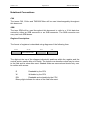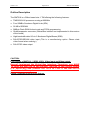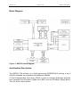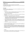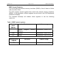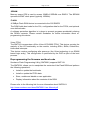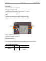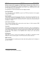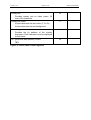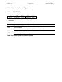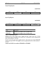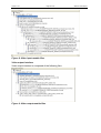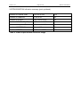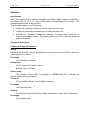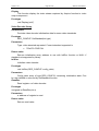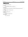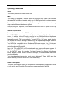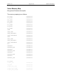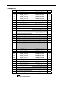
1
SMT319
User Manual
User Manual (QCF42); Version 3.0, 5/2/01; © Sundance Multiprocessor Technology Ltd. 2001
Version 1.0.7
Page 2 of 45
SMT319 User Manual
Revision History
Date
Comments
Engineer
Version
22/09/03
First rev, based on 365
JPA
1.0.0
16/06/04
Updated: output flag register @9007C000
SM
1.0.1
16/07/04
Added: Virtex memory Map
SM
1.0.2
03/09/04
Added: J1, J2, J3, J4 connectors reference
SM
1.0.3
06/09/04
Added: Video cables reference
SM
1.0.4
21/01/05
Updated: PCB layout
SM
1.0.5
18/05/05
Added: Caution Global Bus not implemented
SM
1.0.6
13/10/05
Added: Ordering information section to
distinguish between PAL and NTSC variations.
GP
1.0.7
Version 1.0.7
Page 3 of 45
SMT319 User Manual
Table of Contents
Revision History ....................................................................................................... 2
Contacting Sundance............................................................................................... 7
Contacting Sundance............................................................................................... 7
Notational Conventions ........................................................................................... 8
C60 ......................................................................................................................... 8
SDB ........................................................................................................................ 8
Register Descriptions .............................................................................................. 8
Outline Description .................................................................................................. 9
Block Diagram ........................................................................................................ 10
Architecture Description........................................................................................ 10
TMS320C6416 ......................................................................................................... 11
Boot Mode............................................................................................................. 11
Flash Boot ......................................................................................................... 11
HPI Boot ............................................................................................................ 11
EMIF Control Registers......................................................................................... 12
SDRAM ................................................................................................................. 13
FLASH .................................................................................................................. 13
Virtex FPGA ...................................................................................................... 13
Reprogramming the firmware and boot code ...................................................... 13
Interrupts................................................................................................................. 14
Sundance Digital Links .......................................................................................... 14
SDB .......................................................................................................................... 14
SDB Clock selection ............................................................................................. 14
Global bus ............................................................................................................... 15
Video interfaces...................................................................................................... 16
Video Output Mode Control Register .................................................................... 22
Video Output Status.............................................................................................. 23
Video Input Status................................................................................................. 24
Output Flag Register ............................................................................................. 25
Input Flag Register................................................................................................ 25
Interrupt Control Register...................................................................................... 26
Version 1.0.7
Page 4 of 45
SMT319 User Manual
Connectors location .............................................................................................. 27
Connectors reference ........................................................................................... 27
Video cables reference ......................................................................................... 27
Available resources............................................................................................... 28
Video input interface ............................................................................................. 28
Video output interface ........................................................................................... 29
LED Setting ............................................................................................................. 31
CONFIG & NMI ........................................................................................................ 32
Timer........................................................................................................................ 32
IIOF interrupt........................................................................................................... 32
Code Composer...................................................................................................... 33
Application Development....................................................................................... 34
Software .................................................................................................................. 35
Introduction ........................................................................................................... 35
Functions description ............................................................................................ 35
Sundance Graphical Interface ........................................................................... 35
Video Decoder library ........................................................................................ 36
Video Encoder library ........................................................................................ 37
Operating Conditions ............................................................................................. 38
Safety.................................................................................................................... 38
EMC ...................................................................................................................... 38
General Requirements .......................................................................................... 38
Power Consumption.............................................................................................. 38
PCB Layout Details ................................................................................................ 39
Component Side ................................................................................................... 39
Virtex Memory Map................................................................................................. 40
SHB pin-out............................................................................................................. 41
SMT319 Schematics/FPGA Pin-Out ...................................................................... 42
Ordering Information.............................................................................................. 43
Index ........................................................................................................................ 45
Version 1.0.7
Page 5 of 45
SMT319 User Manual
List of tables
Table 1: EMIF control registers................................................................................. 12
Table 2: SDB clock selection .................................................................................... 14
Table 3: Video output mode control register ............................................................. 22
Table 4: Video output status ..................................................................................... 23
Table 5:Video input status ........................................................................................ 24
Table 6: output flag register ...................................................................................... 25
Table 7: Interrupt control register.............................................................................. 26
Table 8: overall available FPGA resources............................................................... 28
Table 9: Video output module resources usage ....................................................... 30
Version 1.0.7
Page 6 of 45
SMT319 User Manual
List of figures
Figure 1: SMT319 block diagram.............................................................................. 10
Figure 2: SMT319 SDBs location ............................................................................. 14
Figure 3: Video interface block diagram ................................................................... 17
Figure 4: Text overlay example ................................................................................ 19
Figure 5: FPGA video control registers..................................................................... 21
Figure 6: Video connector location ........................................................................... 27
Figure 7: Video connectors....................................................................................... 27
Figure 8: Video input module files ............................................................................ 29
Figure 9: Video output module files .......................................................................... 29
Version 1.0.7
Page 7 of 45
SMT319 User Manual
Contacting Sundance
You can contact Sundance for additional information by login onto the support
system support.sundance.com or sending an email to [email protected].
Version 1.0.7
Page 8 of 45
SMT319 User Manual
Notational Conventions
C60
The terms C60, C64xx and TMS320C64xx will be used interchangeably throughout
this document.
SDB
The term SDB will be used throughout this document to refer to a 16 bit data bus
carried by either an SDB connector or an SHB connector. The SHB connector can
carry two such SDB buses.
Register Descriptions
The format of registers is described using diagrams of the following form:
31–24
23–16
15–8
7–0
R,00000000
R,10000000
OFLAGLEVEL
R,00000000
RW,10000000
The digits at the top of the diagram indicate bit positions within the register and the
central section names bits or bit fields. The bottom row describes what may be done
to the field and its value after reset. Shaded fields are reserved and should only ever
be written with zeroes.
R
Readable by the CPU
W
Writeable by the CPU
RW
Readable and writeable by the CPU
Binary digits indicate the value of the field after reset.
Version 1.0.7
Page 9 of 45
SMT319 User Manual
Outline Description
The SMT319 is a C64xx-based size 1 TIM offering the following features:
TMS320C6416 processor running at 600MHz
Four 20MB/s Sundance Digital Links (SDL)
32 MB of SDRAM
2MByte Flash ROM for boot code and FPGA programming
Global expansion connector (Global Bus interface not implemented in this version
of the board)
High bandwidth data I/O via 2 Sundance Digital Buses (SDB).
PAL/NTSC/SECAM video input (This is a manufacturing option. Please state
video format when ordering.)
PAL/NTSC video output
CAUTION:
First release of SMT319 : 2 SDB, 4 SDL, Video input and Video output.
Doesn’t implement the Global Bus interface. Therefore, you HAVE
TO plug the SMT319 in the second TIM Site of the carrier board
(i.e. SMT310Q) and connect the T1C3 to T2C3 if the SMT319 is
used alone in the system.
Doesn’t implement text overlay feature.
Version 1.0.7
Page 10 of 45
SMT319 User Manual
Block Diagram
Figure 1: SMT319 block diagram
Architecture Description
The SMT319 TIM consists of a Texas Instruments TMS320C6416 running at up to
600MHz. Modules are populated with 32Mbytes SDRAM.
A Field Programmable Gate Array (FPGA) is used to manage global bus accesses
and implement four Sundance Digital links (SDL) and two Sundance Digital Buses.
This is a Xilinx VirtexII device.
Version 1.0.7
Page 11 of 45
SMT319 User Manual
TMS320C6416
The processor will run with zero wait states from internal SRAM.
An on-board crystal oscillator provides the clock used for the C60, which then
multiplies this by 12 internally.
Boot Mode
The SMT319 can be configured to use one of two boot modes after a reset. These
are HPI (host port interface) and Flash.
Flash Boot
1. The processor copies a bootstrap program from the first part of the flash
memory into internal program RAM starting at address 0.
2. Execution starts at address 0.
The standard bootstrap supplied with the SMT319 then performs the following
operations:
1. All relevant C60 internal registers are set to default values;
2. The FPGA is configured from data held in flash memory and sets up the
communication ports, the global bus and the Sundance High-speed Buses.
This step must have been completed before data can be sent to the SDL from
external sources such as the host or other TIMs;
3. A C4x-style boot loader is executed. This will continually examine the four
SDLs until data appears on one of them. The bootstrap will then load a
program in boot format from that port; the loader will not read data arriving on
other ports.
4. Finally, control is passed to the loaded program.
The delay between the release of the board reset and the FPGA configuration is
around 1s for a SMT319 (600MHz clock).
A typical time to wait after releasing the board reset should be in excess of this
delay, but no damage will result if any of the I/Os are used before they are fully
configured. In fact, the comm. Ports will just produce a not ready signal when data
is attempted to be transferred during this time, and then continue normally after
the FPGA is configured.
HPI Boot
The C60’s HPI (16 bit data interface) is connected directly to the FPGA. This
mode is therefore only used by custom FPGA configurations.
Version 1.0.7
Page 12 of 45
SMT319 User Manual
EMIF Control Registers
The C6416 has two external memory interfaces (EMIFs). One of these is 64 bits
wide, the other 8 bits.
The C60 contains several registers that control the external memory interfaces
(EMIFs). A full description of these registers can be found in the C60 Peripherals
Reference Guide[0].
The standard bootstrap will initialise these registers to use the following
resources:
Table 1: EMIF control registers
Resource
Memory
space
Address range
(EMIFA)
Internal
program
(1Mbyte)
memory 0x00000000 - 0x000FFFFF
CE0
SDRAM
0x80000000 - 0x81FFFFFF
CE1
VirtexII
0x90000000 - 0x9FFFFFFF
Memory space
Resource
Address range
(EMIFB)
CE1
Flash
0x64000000 – 0x641FFFFF
Version 1.0.7
Page 13 of 45
SMT319 User Manual
SDRAM
Memory space CE0 is used to access 32MB of SDRAM over EMIFA. The SDRAM
operates at EMIF clock speed (typically 100MHz).
FLASH
A 2MByte Flash ROM device is connected to the C60 EMIFB.
The ROM holds boot code for the C6x, configuration data for the FPGA, and optional
user-defined code.
A software protection algorithm is in place to prevent programs accidentally altering
the ROM’s contents. Please contact Sundance for further information about reprogramming this device.
Virtex FPGA
The SMT319 incorporates a Xilinx Virtex XC2V2000 FPGA. This device controls the
majority of the I/O functionality on the module, including SDLs, SHBs, Global Bus,
timers and interrupts.
This device requires configuring after power-up (the Virtex technology is an SRAM
based logic array). This configuration is performed by the DSP as part of the boot
process.
Reprogramming the firmware and boot code
Sundance Flash Programming Utility (SMT6001) supports SMT319.
The SMT6001, allows you to manipulate the contents of the Flash ROM and perform
the following operations:
•
Install or update the bootloader
•
Install or update the FPGA data
•
Store, enable and disable a user application
•
Display information about the contents of the ROM
Please refer to the following link for more information about SMT6001:
http://www.sundance.com/docs/SMT6001 User Manual.pdf
Version 1.0.7
Page 14 of 45
SMT319 User Manual
Interrupts
See general firmware description [7]
Sundance Digital Links
The SMT319 provides 4 SDLs. They are SDL0, 1, 3, and 4.
See general firmware description [7]
SDB
The SMT319 provides two Sundance Digital Buses (SDB).
They are numbered SDB0 for SDBA and SDB2 for SDBC.
SDBC
SDBA
Figure 2: SMT319 SDBs location
See general firmware description [7]
SDB Clock selection
At any time you can change the speed of an SDB clock by altering SDBCLK.
Table 2: SDB clock selection
Module
SMT319
SDBCLK
Clock Speed
0
50MHz
1
100MHz
Version 1.0.7
Page 15 of 45
SMT319 User Manual
Global bus
This first revision of the SMT319 doesn’t provide any Global Bus interface.
See general firmware description [7]
Version 1.0.7
Page 16 of 45
SMT319 User Manual
Video interfaces
Connected to the FPGA is a BT829 composite video decoder and a BT864A
composite/RGB video encoder.
Video interfaces can sustain C64 EMIFA rate of 380Mbyte/sec.
Data from and to these devices are routed through the FPGA as shown in the
diagram below:
Version 1.0.7
Page 17 of 45
SMT319 User Manual
Not available in this release of the SMT319
Figure 3: Video interface block diagram
Version 1.0.7
Page 18 of 45
SMT319 User Manual
With the maximum PAL resolution of 768x576 with 16 bits per pixel (YCrCb 4:2:2), a
full frame will consume 884736 bytes thus allowing for 37 complete frames to be
stored. Using QCIF NTSC square pixels, each frame is only 19200 bytes and a total
of 1747 colour frames can be stored.
An explanation of each functional block of the diagram follows.
Pixel Input Register
The 16-bit data from the Bt829B is input to the FPGA and latched in this register
using the QCLK signal.
Pixel Formatter*
This creates an internal 24-bit sample with each Y value being accompanied by a Cr
and Cb value. Data from the Bt829B is in the form of YCb, YCr, YCb, YCr, etc. The
formatter will create samples in which the Cb and Cr values will be identical between
successive Y values.
Colour Space Converter*
This converter will take YCbCr pixels and convert these to 24-bit computer RGB
values, or 16-bit 565 RGB values.
Threshold*
This operation basically performs a translation on the 8-bit Y value. The translation is
accomplished by inputting the Y value into a LUT (look-up table) and the transformed
value is then output. The LUT must be programmed by the DSP, and can be altered
at any time. If this feature is not required, then a ramp (0,1,2, etc) must be
programmed.
FIFO Buffer(s)
This FIFO is used to remove the necessity for the EMIF to continually access
SDRAM to store or retrieve pixels. The FIFO can store a whole video line.
EMIF Controller
This is responsible for transferring the video data (both grabbed and for display) to
the DSP’s EMIFA.
*
not available in the first release of the SMT319
Version 1.0.7
Page 19 of 45
SMT319 User Manual
Overlay Text & Character Generator*
A 1k byte memory within the FPGA is able to store a 40x25 screen-full of characters.
Each character may take on any value between 1 and 127. A value of 0 indicates
that the character will not be displayed. A character value with bit 7 (128 to 255) set
indicates that the white character will be displayed within a black square, as opposed
to white on top of the underlying colours.
Figure 4: Text overlay example
The above picture shows white characters overlaid on top of the picture (bit 7 = 0),
and white characters overlaid with a black background (bit 7 = 1).
Mixer*
This simply superimposes the character generator output on top of the normal video
stream.
Video Output Data Control
The Bt864A produces HSYNC and VSYNC signals, which inform the output data and
HPI controllers to fetch and shift out the correct pixel data.
*
not available in the first release of the SMT319
Version 1.0.7
Page 20 of 45
SMT319 User Manual
FPGA Video Control Registers
Function
Size (bytes)
Address
1k
-
256
-
1024
0x90050000
Video input Status Register
4
0x90058000
Video input pixels per frame
4
-
4
0x90054000
1
0x900E4000
Colour space converter control
Optional
Threshold
256 byte LUT
Video input FIFO
16 bit wide YC FIFO
Readable via or EMIFA
Max pixels per frame is < 500k
Video Input Flag Register
Sets the point at which an interrupt is
generated
Interrupt enable
Video input/output interrupt enable
0x900EC000
0x900F4000
0x900FC000
I2C Control
16
-
1024
0x90070000
Video Output Status Register
4
0x90078000
Video output mode control
1
0x90078800
4
0x9007C000
Video output FIFO
16 bit wide YC FIFO
Writeable via EMIFA
This determines the number of pixels per line,
and lines per frame.
Video Output Flag Register
Sets the point at which an interrupt is
generated
Version 1.0.7
Page 21 of 45
Overlay text
SMT319 User Manual
1k
-
6
-
1k
-
1k
-
Provides overlay text on video output. 25
rows of 40 characters
Overlay text colour
3 bytes determine the text colour (Y Cr Cb)
3 bytes determine the text background
Character generator
Provides the bit patterns of the overlay
characters. Each character must be displayed
in both fields.
PDT (peripheral data transfer) control
TBD
Figure 5: FPGA video control registers
Version 1.0.7
Page 22 of 45
Video Output Mode Control Register
Address: 0x90078800
31
30..22
21..12
11..10
9..0
INTL
-
LPD
-
PPL
RW,0
RW,0x240
RW,0x2D0
- : reserved
Field
Description (flags are active when 1)
INTL
Not interlaced
LPD
Number of lines per display
PPL
Number of pixels per display
0 Interlaced mode
1 Not interlaced mode
Table 3: Video output mode control register
SMT319 User Manual
Version 1.0.7
Page 23 of 45
SMT319 User Manual
Video Output Status
Address:0x90078000
31
30
29
28
27
26
25
24
23–16
-
OER
-
OFLAG
-
-
OFF
OFE
-
0
R,0
0
R,1
0
1
R,0
R,1
00000000
15–8
7
6
5
OFL
TRANS
-
R,11111111
RW,0
0
4
3
2
1
0
DIS
-
-
CLROF
DIR
RW,0
0
0
W,0
R,0
- : reserved
Field
Description (flags are active when 1)
DIR
Transfer direction
CLROF
Clear outgoing FIFO
DIS
1 Writing
0
Pause transmission when FIFO is full
1
Continue transmission even when FIFO full
TRANS
Set to 1 after reset to make this SDB start as a transmitter
OFL
Outgoing FIFO Level: number of words that can be written
OFE
Outgoing FIFO Empty
OFF
Outgoing FIFO Full
OFLAG
Outgoing FIFO Flag. Set when OFLAGLEVEL writes can be performed.
OER
Output error. The DSP has written to a full output FIFO.
Table 4: Video output status
Version 1.0.7
Page 24 of 45
SMT319 User Manual
Video Input Status
Address:0x90058000
31
30
29
28
27
26
25
24
23–16
IER
-
IFLAG
-
IFF
IFE
-
-
IFL
R,0
0
R,0
1
R,0
R,1
0
1
R,00000000
15–8
7
6
5
-
-
-
11111111
0
0
4
3
2
1
0
DIS
-
CLRIF
-
DIR
RW,0
0
W,0
0
R,0
- : reserved
Field
Description (flags are active when 1)
DIR
Transfer direction
CLRIF
Clear incoming FIFO
DIS
0 Reading
0
Pause transmission when FIFO is full
1
Continue transmission even when FIFO full
IFL
Incoming FIFO Level: number of words that can be read
IFE
Incoming FIFO Empty
IFF
Incoming FIFO Full
IFLAG
Incoming FIFO Flag. Set when IFLAGLEVEL reads can be performed.
IER
Input error. The DSP has read from an empty input FIFO.
Table 5:Video input status
Version 1.0.7
Page 25 of 45
SMT319 User Manual
Output Flag Register
0x9007C000
31–24
23–16
15–8
7–0
R,00000000
R,10000000
OTRIGGER
R,00000000
RW,10000000
Input Flag Register
0x90054000
31–24
23–16
15–8
7–0
ITRIGGER
R,00000000
R,10000000
R,00000000
Field
Description
OTRIGGER
Outgoing FIFO trigger. Set to 128 after reset.
ITRIGGER
Incoming FIFO trigger. Set to 128 after reset.
RW,10000000
Table 6: output flag register
OFLAG in the Video Output status register will be 1 when there are at least
OTRIGGER spaces available in the output FIFO. OTRIGGER must be programmed
with a value between 1 and 255.
IFLAG in the Video Input status register will be 1 when there are at least ITRIGGER
words in the input FIFO. This register must be programmed with a value between 1
and 255.
CLRIF and CLROF do not affect OTRIGGER or ITRIGGER.
Version 1.0.7
Page 26 of 45
SMT319 User Manual
Interrupt Control Register
The Interrupt Control register is described in the general firmware description [7].
The register has been slightly modified to integrate video input and output
functionalities:
31–30
29–28
SDB0 IE VIDIN IE
27–26
25–24
SDB2 IE
23–22
21–20
19–18
17–16
VIDOUT
SDB4 IE SDB5 IE SDB6 IE SDB7 IE
IE
RW,00
RW,00
RW,00
RW,00
RW,00
RW,00
RW,00
RW,00
15–14
13–12
11–10
9–8
7–6
5–4
3–2
1–0
SDB8 IE SDB9 IE SDB10 IE SDB11 IE SDB12 IE SDB13 IE SDB14 IE SDB15 IE
RW,00
RW,00
RW,00
RW,00
RW,00
RW,00
RW,00
RW,00
Field
Description
Interrupt condition selected
SDBx IE (bit 0)
SDB IFLAG Interrupt Enable
≥ IFLAGLEVEL words available
SDBx IE (bit 1)
SDB OFLAG Interrupt Enable
≥ OFLAGLEVEL spaces available
VIDIN IE (bit 0) VIDIN IFLAG Interrupt Enable ≥ IFLAGLEVEL words available
VIDOUT IE (bit VIDOUT
1)
Enable
OFLAG
Interrupt
≥ OFLAGLEVEL spaces available
Table 7: Interrupt control register
VIDIN IE bit 1 and VIDOUT IE bit 0 are not implemented.
Version 1.0.7
Page 27 of 45
SMT319 User Manual
Connectors location
Analog Composite
Video Input
Video out: Y
Video
Cr&Cb
out:
Figure 6: Video connector location
Connectors reference
Connectors J1, J2, J3, J4 used as input/output connectors are SMB PCB straight 50
ohms connectors. Farnell provides them under the reference 310-682, and these
connectors are manufactured by TYCO/ELECTRONICS/MA-COM.
Figure 7: Video connectors
Video cables reference
Specific video cables such as SMB/Video RCA cable are suitable.
Version 1.0.7
Page 28 of 45
SMT319 User Manual
FPGA design
FPGA has been design in VHDL, following Xilinx Modular Design rules.
Following modules are available:
•
Decode: C6x interface.
•
2xSDB
•
4xSDL
•
GB (not available in this release of SMT319)
•
VideoIn
•
VideoOut
Modular design allows you to replace some of these modules by your custom
modules without having to re-place and route the whole firmware of the board.
Available resources
The following table presents the VirtexII 2000 FF896 utilisation by Sundance
firmware:
Number of External IOBs
332 out of 624
53%
Number of RAMB16s
12 out of 56
21%
Number of SLICEs
3696 out of 10752
34%
Number of BUFGMUXs
3 out of 16
18%
Number of TBUFs
1420 out of 5376
26%
Table 8: overall available FPGA resources
Video input interface
Video output interface is composed of the following files:
Version 1.0.7
Page 29 of 45
Figure 8: Video input module files
Video output interface
Video output interface is composed of the following files:
Figure 9: Video output module files
SMT319 User Manual
Version 1.0.7
Page 30 of 45
SMT319 User Manual
VIRTEXII2000FF896 utilization summary (post-synthesis):
Number of External IOBs
332 out of 624
53%
Number of RAMB16s
2 out of 56
3%
Number of SLICEs
222 out of 10752
2%
Number of SLICEs Flip-Flops
292 out of 21504
1%
Number of 4 input LUTs
299 out of 21504
1%
Number of BUFGMUXs
0 out of 16
0%
Number of TBUFs
1420 out of 5376
26%
Table 9: Video output module resources usage
Version 1.0.7
Page 31 of 45
SMT319 User Manual
LED Setting
The SMT319 has 9 LEDs.
LED D1 always displays the state of the FPGA DONE pin. This LED is off when the
FPGA is configured (DONE=1) and on when it is not configured (DONE=0).
This LED should go on when the board is first powered up and go off when the FPGA
has been successfully programmed (this is the standard operation of the boot code
resident in the flash memory device). If the LED does not light at power-on, check
that you have the mounting pillars and screws fitted properly. If it stays on, the DSP
is not booting correctly, or is set to boot in a non-standard way.
Four of the LEDs (D7-10) can be controlled with the LED register. Writing 1 will
illuminate the LED; writing 0 will turn it off.
LED Register
LED 0x900D0000
31–4
3
2
1
0
LED
D10
LED
D9
LED
D8
LED
D7
RW,0
RW,0
RW,0
RW,0
The four remaining LEDs (D2-5) are connected to the C60’s GPIO pins 12-15.
Version 1.0.7
Page 32 of 45
SMT319 User Manual
CONFIG & NMI
See general firmware description [7]
Timer
See general firmware description [7]
IIOF interrupt
The firmware can generate pulses on the external interrupt lines of the TIM.
See general firmware description [7]
Version 1.0.7
Page 33 of 45
SMT319 User Manual
Code Composer
This module is fully compatible with the Code Composer Studio (CCS) debug
environment (version 2 or later). This extends to both the software and JTAG
debugging hardware.
The name of the C64xx CCS device driver is tixds64xx_11.dvr, and should be
obtained from Texas Instruments. In case of difficulty please contact
[email protected].
FIRST TIME DOWNLOAD
When you open CCS and want to download an application, after power up, you might
get the following error message:
“Can’t set breakpoint: Cannot set/verify breakpoint at 0x8C40” (the address might be
different)
Workaround: Reset the board first with a server or you should infer a CPU Reset
from Debug\reset CPU. Then you should run the processor.
You can then stop the processor and load your application
Version 1.0.7
Page 34 of 45
SMT319 User Manual
Application Development
You can develop code for SMT319 modules in several ways. The simplest is to use
the Sundance SMT6000 Server Loader and its associated libraries (shortly to be
discontinued).
The Server Loader is an application that runs on a host PC under either Windows 98,
2000 or NT and allows you to run COFF-format applications. Modified forms of the TI
RTS library support standard C I/O.
The Server Loader will read a .out file and convert it into C4x-style boot code which
is then transmitted down a comm-port to the SMT319.
The boot code is in the following format:
6-word
header
Load Block
Word1 1
0
Words 2, 3, 4
0, 0, 0
Word 5
start address
Word 6
0
Word 1
4*N: Length of load block (in bytes)2
Word 2
Destination address (external memory only)
Next N words
N data words
Word 1
03
Reserved
0 or more
Load Blocks
Terminator
1
A word is 32 bits
2
The length of each data block will be rounded up to a multiple of 4 bytes if necessary.
3
Effectively a zero-length Load Block
Version 1.0.7
Page 35 of 45
SMT319 User Manual
Software
Introduction
SMT319 is comes with a software package, providing a basic example (loopback.c)
decoding a PAL, B, D, G, H, I input video stream and displaying it to a screen. This
example doesn’t claim to be real time.
This example makes use of 3 libraries:
•
VidEnc.lib: provides functions to set-up video encoder chip.
•
VidDec.lib: provides functions to set-up video decoder chip.
•
SndGrInt.lib: Sundance Graphical Interface. Provides basic functions to
acquire and display images. This library makes use of 3L real time operating
system, Diamond.
Functions description
Sundance Graphical Interface
InitLib
Initialises the SndGrInt library. Applications must call this function before using any
other feature of he library.
Prototype
int InitLibrary(int bufsize)
Parameters
Count: number of frames to store
Bufsize: size of a frame
Return value
This function returns OK if successful or MEMNOTALLOC if memory for
buffers could not been allocated.
CloseLib
Close SndGrInt library. Free SndGrInt memory.
Prototype
void CloseLib(void)
Acquire
This function acquires the video stream connected to video input component.
Prototype
void Acquire(void*)
Version 1.0.7
Page 36 of 45
SMT319 User Manual
Display
This function display the video stream captured by Acquire function to video
output component.
Prototype
void Display(void*)
Video Decoder library
GetStandard
Provides video decoder initialisation data for some video standards.
Prototype
REG_CONFIG* GetStandard(int type)
Parameters
Type: video standard requested. Current standard supported is:
•
720x576 CCIR PAL
Return value
Returns initialisation array address to use with InitDec function or NULL if
standard not supported by library.
InitDec
Initialises video decoder.
Prototype
void InitDec(REG_CONFIG* config_data)
Parameters
Config_data: array of type REG_CONFIG, containing initialisation data. Can
be user defined or returned by GetStandard function.
ReadDec
Read register a of video decoder.
Prototype
unsigned int ReadDec(int a)
Parameters
a: address of register to read.
Return value
Returns read value.
Version 1.0.7
Page 37 of 45
SMT319 User Manual
Video Encoder library
InitEnc
Initialises video decoder.
Prototype
void InitEnc(REG_CONFIG* config_data)
Parameters
Config_data: array of type REG_CONFIG, containing initialisation data.
ReadEnc
Read register a of video encoder.
Prototype
unsigned int ReadEnc(int a)
Parameters
a: address of register to read.
Return value
Returns read value.
Version 1.0.7
Page 38 of 45
SMT319 User Manual
Operating Conditions
Safety
The module presents no hazard to the user.
EMC
The module is designed to operate within an enclosed host system that provides
adequate EMC shielding. Operation within the EU EMC guidelines is only guaranteed
when the module is installed within an appropriate host system.
The module is protected from damage by fast voltage transients introduced along
output cables from outside the host system.
Short-circuiting any output to ground does not cause the host PC system to lock up
or reboot.
General Requirements
The module must be fixed to a TIM40-compliant carrier board.
The SMT319 TIM is in a range of modules that must be supplied with a 3.3v power
source. In addition to the 5v supply specified in the TIM specification, these new
generation modules require an additional 3.3v supply to be presented on the two
diagonally-opposite TIM mounting holes. The lack of this 3.3v power supply should
not damage the module, although it will obviously be inoperable; prolonged operation
under these circumstances is not recommended.
The SMT319 is compatible with all Sundance TIM carrier boards. It is a 5v tolerant
module, and as such, it may be used in mixed systems with older TIM modules,
carrier boards and I/O modules.
Use of the TIM on SMT327 (cPCI) motherboards may require a firmware upgrade. If
LED D6 on the SMT319 remains illuminated once the TIM is plugged in and powered
up, the SMT327 needs the upgrade. The latest firmware is supplied with all new
boards shipped. Please contact Sundance directly if you have an older board and
need the upgrade.
The external ambient temperature must remain between 0°C and 40°C, and the
relative humidity must not exceed 95% (non-condensing).
Power Consumption
The power consumption of this TIM is dependent on the operating conditions in terms
of core activity and I/O activity. The maximum power consumption is 10W.
Version 1.0.7
PCB Layout Details
Component Side
Page 39 of 45
SMT319 User Manual
Version 1.0.7
Page 40 of 45
Virtex Memory Map
See general firmware description.
The memory mapping is as follows:
CP0_FIFO
0x90000000
CP0_STAT
0x90004000
CP1_FIFO
0x90008000
CP1_STAT
0x9000C000
CP3_FIFO
0x90018000
CP3_STAT
0x9001C000
CP4_FIFO
0x90020000
CP4_STAT
0x90024000
SDBA
0x90040000
SDBA_STAT
0x90048000
SDBA_INPUTFLAG
0x90044000
SDBA_OUTPUTFLAG
0x9004C000
SDBC
0x90060000
SDBC_STAT
0x90068000
SDBC_INPUTFLAG
0x90064000
SDBC_OUTPUTFLAG
0x9006C000
LED
0x900D0000
INTCTRL4
0x900E0000
INTCTRL4_EXT
0x900E4000
INTCTRL5
0x900E8000
INTCTRL5_EXT
0x900EC000
INTCTRL6
0x900F0000
INTCTRL6_EXT
0x900F4000
INTCTRL7
0x900F8000
INTCTRL7_EXT
0x900FC000
Not Available:
GLOBAL_BUS
0x900A0000
GB_STAT
0x90034000
GLOBAL_BUS_CTRL
0x90080000
GLOBAL_BUS_START
0x90088000
GLOBAL_BUS_LENGTH
0x90090000
SMT319 User Manual
Version 1.0.7
Page 41 of 45
SMT319 User Manual
SHB pin-out
Pin
Signal
Signal
Pin
1
SDBA_CLK
SDBA_DATA0
2
3
SDBA_DATA1
SDBA_DATA2
4
5
SDBA_DATA3
SDBA_DATA4
6
7
SDBA_DATA5
SDBA_DATA6
8
9
SDBA_DATA7
SDBA_DATA8
10
11
SDBA_DATA9
SDBA_DATA10
12
13
SDBA_DATA11
SDBA_DATA12
14
15
SDBA_DATA13
SDBA_DATA14
16
17
SDBA_DATA15
SDBA_U0
18
19
SDBA_U1
-
20
21
-
SDBA_WEN
22
23
SDBA_REQ
SDBA_ACK
24
25
-
-
26
27
-
-
28
29
-
-
30
31
-
-
32
33
-
-
34
35
-
-
36
37
SDBB_CLK
SDBB_DATA0
38
39
SDBB_DATA1
SDBB_DATA2
40
41
SDBB_DATA3
SDBB_DATA4
42
43
SDBB_DATA5
SDBB_DATA6
44
45
SDBB_DATA7
SDBB_DATA8
46
47
SDBB_DATA9
SDBB_DATA10
48
49
SDBB_DATA11
SDBB_DATA12
50
51
SDBB_DATA13
SDBB_DATA14
52
53
SDBB_DATA15
SDBB_U0
54
55
SDBB_U1
-
56
57
-
SDBB_WEN
58
59
SDBB_REQ
SDBB_ACK
60
Not implemented
Version 1.0.7
Page 42 of 45
SMT319 User Manual
SMT319 Schematics/FPGA Pin-Out
Please ask Sundance Multiprocessor Technology Ltd to obtain SMT319 schematics.
Version 1.0.7
Ordering Information
SMT319-PAL
SMT319-NTSC
Page 43 of 45
SMT319 User Manual
Version 1.0.7
Page 44 of 45
SMT319 User Manual
Bibliography
1. TMS320C6201/C6701 Peripherals Reference Guide (literature number SPRU190)
http://www-s.ti.com/sc/psheets/spru190d/spru190d.pdf
Describes common peripherals available on the TMS320C6201/C6701 digital signal processors.
This book includes information on the internal data and program memories, the external memory
interface (EMIF), the host port, multichannel-buffered serial ports, direct memory access (DMA),
clocking and phase-locked loop (PLL), and the power-down modes.
2. TIM-40 MODULE SPECIFICATION Including TMS320C44 Addendum
ftp://ftp2.sundance.com/Pub/documentation/pdf-files/tim_spec_v1.01.pdf
3. SDB Technical Specification
ftp://ftp2.sundance.com/Pub/documentation/pdf-files/sdb_tech_spec.pdf
4. SHB Technical Specification
ftp://ftp2.sundance.com/Pub/documentation/pdf-files/SHB_Technical_Specification_v1_0.pdf
5. TMS320C4x User's Guide (literature number SPRU063)
http://www-s.ti.com/sc/psheets/spru063c/spru063c.pdf
Describes the C4x 32-bit floating-point processor, developed for digital signal processing as well
as parallel processing applications. Covered are its architecture, internal register structure,
instruction set, pipeline, specifications, and operation of its six DMA channels and six
communication ports. Software and hardware applications are included.
6. Xilinx Virtex-II data sheet:
http://www.xilinx.com/
7. General firmware description:
ftp://ftp2.sundance.com/Pub/documentation/pdf-files/External_Interface_User_manual.pdf
Version 1.0.7
Page 45 of 45
SMT319 User Manual
Index
Application Development...............34
server-loader.................................34
Architecture Description................10
Bibliography....................................44
Block Diagram ................................10
Board not working
LED 6 illuminated..........................31
boot code format ............................34
Boot Mode .......................................11
bootstrap program .........................11
carrier boards .................................38
Code Composer..............................33
Contacting Sundance.......................7
email address....................................7
EMIF Control Registers ..................12
field values after reset......................8
Flash ................................................13
protection algorithm ......................13
FPGA ...............................................10
configuration .................................11
Input Flag Register .........................25
LEDs ................................................31
FPGA DONE pin ...........................31
LED register ................................. 31
memory space (CE0 to CE3) ......... 12
motherboards................................. 38
NMI .................................................. 32
Notational Conventions .................. 8
Operating Conditions .................... 38
Output Flag Register ..................... 25
Power
3.3v .............................................. 38
power consumption ...................... 38
RAM ................................................ 13
register descriptions ....................... 8
Schematics/FPGA Pin-Out ............ 43
SDB ................................................. 14
clock speed .................................. 14
Timer............................................... 32
TMS320C6201................................. 11
Video Input status.......................... 24
Video output mode control register
......................................................... 22
Video output status ....................... 23
Virtex Memory Map........................ 41