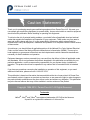
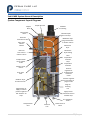
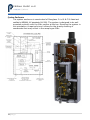
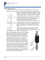
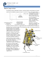
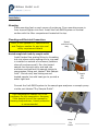
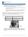
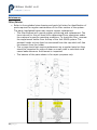
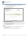
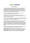
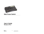
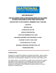
1
Indi-GASS Module™ Model GM-1024 Sample Conditioning System featuring Nafion® Membrane Drying Technology User Manual PERMA PURE LLC 8 Executive Drive ▪ Toms River, NJ 08755 (732) 244-0010 ▪ (800) 337-3762 ▪ fax (732) 244-8140 ▪ www.permapure.com ▪ [email protected] PERMA PURE LLC Table of Contents Unpacking .......................................................................5 Important safety warnings ................................................9 Indi-GASS System General Description ............................. 11 System Component Layout Diagram .................................................................................................... 11 System Enclosure .................................................................................................................................. 12 Filter/Eductor ........................................................................................................................................ 13 Nafion® Membrane dryer...................................................................................................................... 14 “Heatless” purge air dryer..................................................................................................................... 15 Installation.................................................................... 16 Mounting ............................................................................................................................................... 16 Plumbing and Electrical Connections ................................................................................................... 16 System Commissioning ................................................... 18 Start-up Check (Indi-GASS commissioning/troubleshooting kit req’d) ......................................... 18 Maintenance .................................................................. 20 Filter/Eductor ........................................................................................................................................ 20 Nafion® Membrane dryer...................................................................................................................... 21 “Heatless” purge air dryer..................................................................................................................... 22 APPENDIX A: ................................................................. 25 Specifications and Features .................................................................................................................. 25 3|Page PERMA PURE LLC Utility Requirements Summary ............................................................................................................ 27 APPENDIX B: ................................................................. 29 Drawings ............................................................................................................................................... 29 APPENDIX C: ................................................................. 31 Warranty and disclaimers ..................................................................................................................... 31 APPENDIX D: ................................................................ 33 Indi-GASS Commissioning/troubleshooting kit ................................................................................... 33 4|Page PERMA PURE LLC Unpacking Perma Pure has made every effort to ship you a high quality product that has been thoroughly inspected and tested. It has been carefully packed to ensure that it arrives at your facility in good condition. Even though every effort has been made to prevent damage during transportation, damage can occur by the carrier. This is out of Perma Pure’s control and is the responsibility of the carrier to ensure that your equipment arrives intact and undamaged. Inspect outside packaging. If there is any visible damage, inform the carrier at the time of delivery. This inspection is important! Once the package is signed for, responsibility for any visible damage then transfers to the consignee. Unpack your equipment. Visually inspect the outside of your equipment for any damage. If there is any damage, contact the carrier immediately. Generally, a carrier must be notified within 24 hours of the delivery to make a hidden damage claim. Save the packing material in the event a damage claim must be verified by the carrier. Items in the carton include: (1) Indi-GASS sampling system (1) Heated line seal fitting (1) User’s Manual If any of the above parts are missing or damaged, call the helpline at (800) 337-3762 ext-149. 5|Page PERMA PURE LLC Caution Statement Thank you for purchasing sample gas conditioning equipment from Perma Pure LLC. We want your new sample gas conditioning equipment to operate safely. Anyone who installs or uses this equipment should read this publication before installing or operating this equipment. To minimize the risk of potential safety problems, you should follow all applicable local and national codes that regulate the installation and operation of your equipment. These codes vary from area to area and usually change with time. It is your responsibility to determine which codes should be followed and to verify the equipment, installation and operation is in compliance with the latest revision of these codes. At a minimum, you should follow all applicable sections of the National Fire Code, National Electrical Code, and the codes of the National Electrical Manufacturer’s Association (NEMA). There may be local regulatory or government offices that can also help determine which codes and standards are necessary for safe installation and operation. Equipment damage or serious personal injury can result from the failure to follow all applicable codes and standards. We do not guarantee the products described in this publication are suitable for your particular application, nor do we assume any responsibility for your system design, installation or operation. This product should not be operated in any manner that is inconsistent with its intended use. If you have any questions concerning the installation or operation of this equipment, or you need additional information, please call us at 1-800-337-3762. TRADEMARKS This publication is based on information that was available at the time it was printed. At Perma Pure we constantly strive to improve our products and services, so we reserve the right to make changes to the products and/or publications at any time without notice and without any obligation. This publication may also discuss features that may not be available in certain revisions of the product. Trademarks Copyright 1996-2012, Perma Pure LLC All Rights Reserved Trademarks Nafion®, Viton® and Teflon® are registered trademarks of EI DuPont de Nemours Kynar® is a registered trademark of Arkema Inc. 7|Page PERMA PURE LLC Important safety warnings Please be sure to review the following basic safety procedures. These procedures represent the MINIMUM requirements to operate the equipment safely. It is the ultimate responsibility of the operator to ensure proper safety practices are utilized at the point of operation. This equipment is NOT designed to operate in a wet environment. Condensate is potentially dangerous. NEVER handle drain lines or any other item that may have come in contact with the gas stream or any hazardous material, without adequate personal protective equipment. ALWAYS assume that any liquid present is hazardous. Sample gas is potentially dangerous. A leak test is recommended at initial startup and as often as necessary to maintain a safe working environment around the equipment. The gas stream exhaust must exit away from all personnel to prevent dangerous exposure. NEVER operate the equipment with any part of the enclosure unsecured. All operated doors and covers must be in place and secured prior to operation. Electrical current may be present behind covers or doors, even if tools are not necessary to access these components. NEVER attempt service on this equipment without first disconnecting all energy sources. Repair of this equipment should only be done by properly trained personnel that are familiar with the potential risks involved with servicing of the equipment. NEVER replace fuses with types other then the sample specification of type and current. Do not bypass this or any other safety device. NEVER operate this equipment if it is visibly damaged or the possibility exists that it may have been damaged. The use of components that have not been purchased through an authorized Perma Pure dealer or directly from Perma Pure may compromise the safety of the operator. Additionally, use of non-authorized components may change the operating characteristics of this equipment. Any changes to the equipment that modify its operation in any way are dangerous, and are strictly prohibited. Read the entire operating manual before attempting to set up or operate the equipment. Please heed all warning labels that are on the equipment. They are there to remind you of possible hazardous conditions. Verify the integrity of any mechanical and/or electrical connections that are made to the unit. Verify that the unit is connected to the proper rated power for the system. Verify that the unit is plumbed properly 9|Page PERMA PURE LLC Indi-GASS System General Description System Component Layout Diagram Sample filter Sample gas inlet Filter heating sleeve Umbilical line sealing fitting Filtered sample gas line to dryer Drain line from filter to valve Membrane dryer purge exhaust line to eductor suction Filter drain/ Eductor exhaust Membrane dryer Membrane dryer heating sleeve Filter temperature controller Drain line from valve to eductor suction Compressed air line to eductor nozzle Dryer temperature controller Heatless” dryer control Pressure regulator for compressed air to eductor nozzle Drain valve timer Pressure regulator for instrument air purge air inlet “Heatless” dryer for Instrument air Purge air metering line High pressure air supply to eductor pressure regulator and “heatless” air dryer High pressure Instrument air from heatless dryer Dry sample gas outlet Compressed air inlet Electrical hub Power terminal block 11 | P a g e PERMA PURE LLC System Enclosure The system enclosure is constructed of fiberglass. It is UL & C UL listed and certified to NEMA 4, 4X standards (UL 508). The system is designed to be wall mounted vertically with the filter section at the top. Mounting the system in this orientation is required since it allows for the gravity draining of condensate that may collect in the sample gas filter. 12 | P a g e PERMA PURE LLC Filter/Eductor Consisting of parts machined from solid Kynar® (PVDF) fluoro-polymer, the filter body is designed to hold a standard size, coalescing filter element for the purpose of removing particulate matter and high boiling point liquids like sulfuric acid. To prevent water from condensing in the filter and causing the possible loss of water soluble analyte gases, the filter is surrounded by a heated aluminum sleeve. The temperature is controlled by a simple analog temperature controller that is factory set at 80C. The particulate matter is removed by collection on the filter element and any liquids are removed by first coalescing on the filter element and then collecting at the bottom of the filter bowl. Since the Indi-GASS system is typically located upstream of the sample pump, the sample gas in the system is under slight vacuum. In order to remove the liquid, a vacuum higher than the vacuum inside the filter is required. Integral to the filter body and below the filter bowl is an “eductor” section. By passing compressed air through an orifice, the Venturi effect generates a Filter element vacuum in the eductor. An adjustable regulator controls pressure to the eductor. Extraction Heated sleeve of the collected liquid from the filter is accomplished in a controlled manner by an adjustable cycle timer that operates a Kynar® solenoid valve. The valve connects the sump Drain/Exhaust area of the filter to the vacuum of the eductor. When open, the liquid flows through the valve and back to the eductor section where it combines with the eductor exhaust and exits the system. In addition to the drain function of Kynar®® the eductor, the membrane dryer solenoid valve exhaust also connects to the eductor for periodic suction port. More information on Eductor (internal) evacuation of this is located in the membrane coalescing filter dryer description section. 13 | P a g e PERMA PURE LLC Nafion® Membrane dryer Consisting of a PD series membrane dryer and a heated mounting block assembly. Its sole purpose is to remove water vapor from the sample gas stream. Drying is accomplished by a number of small diameter “hollow fiber” tubes extruded from a unique polymer called Nafion®. While essentially a modified Teflon material, Nafion® retains all of the chemical resistance and inertness of Teflon but has additional properties that allow it to remove water vapor without otherwise altering the gas composition. This makes Nafion® the ideal material for drying analytical sample gases. To ensure the water present in the sample gas remains in the vapor phase, the membrane dryer is mounted in a heated aluminum block. The temperature is controlled by a simple analog temperature controller that is factory set at 100C. As the sample gas flows through the hollow fiber Nafion tubes, the water vapor contained in the sample gas reacts chemically with the surface of the Nafion material. Water vapor is thereby drawn out of the sample gas, into the walls of the hollow fiber tubes and evaporates into the dry purge air that sweeps across the outside surface of the tubes. The purge gas flow rate is controlled by the pressure regulator/orifice tube combination located between the heatless dryer outlet and membrane dryer purge inlet. As mentioned above, the purge air exhaust is connected to the eductor suction port. Because the sample gas is under vacuum and the Nafion membrane tubes are very thin walled, they will eventually collapse Heating/ and block the sample flow if allowed to operate mounting under vacuum for an extended period of time. To block prevent this, the purge exhaust pressure is reduced by the eductor to a level that is slightly below sample gas pressure. The dry purge air is PD Nafion® supplied to the membrane dryer via the “heatless dryer dryer” subassembly described below. 14 | P a g e PERMA PURE LLC “Heatless” purge air dryer Consisting of twin desiccant columns, solenoid valves and electronic timing controls, the heatless purge air dryer is a point-of-use, self-regenerating, compressed air dryer. It is located in the lower part of the enclosure and provides dry purge air to the Nafion® membrane sample gas dryer. The heatless dryer operates on the pressure swing adsorption principle where one cylinder acts to dry the air under pressure while the second is regenerated with a small portion of the dry air supplied from the first cylinder. On a fixed time cycle, the valves switch the drying function to the second cylinder and the first cylinder is regenerated by a small portion Solenoid valves of the air dried in the second cylinder. A burst of air can be heard on a 30 second cycle when the valves switch. This is normal. Venting this air directly into the enclosure creates a Eductor air pressure small positive pressure which regulator will prevent the entry of ambient air into the enclosure. Depending on the system’s installation location the ambient air may be corrosive and if Purge air pressure allowed to enter could cause regulator damage. This cycle repeats indefinitely as long as the AC power and air utilities are available. Refer to Appendix A for details on compressed air Desiccant cylinders requirement. Compressed air inlet 15 | P a g e PERMA PURE LLC Installation Mounting Place mounting feet on each corner of enclosure. Drop mounting screw in from top and tighten into foot. Install the Indi-GASS system on vertical surface with the filter compartment located at the top. Plumbing and Electrical Connections Refer to the Appendix A, Specifications and Features section for port size and utility requirement details Heated umbilical line entry Heated sample inlet and dry sample outlet Install heated line sealing fitting by threading hub into sleeve while making sure o-ring seal is installed on outside of enclosure (between sleeve & enclosure wall). Run the heated sample line through entry seal and into enclosure and connect the sample tubing to compression fitting port labeled “Wet Sample Inlet”. Shrink entry seal tubing around heated sample line with heat gun to provide a water tight seal. Sample Gas Inlet Connect the Indi-GASS system to the sample gas analyzers or sample pump via the port labeled “Dry Sample Outlet”. High temperature heated line is not necessary for this connection. However, if the sample line will be exposed to freezing temperatures, freeze protection is recommended. 16 | P a g e Sample Gas Outlet PERMA PURE LLC Compressed air supply Connect a 60-100 psig, oil-free compressed line to the ¼” female NPT inlet port labeled “Compressed Air Inlet”. If the air supply contains oil, which is typical of compressed air where the source is an oil lubricated compressor, a high quality oil mist/vapor filter capable of removing oil mist and aerosols to 99.9% and particles sized down to 0.3um is required. Oil in the compressed air can cause premature failure of the compressed air dryer. Compressed Air Inlet Membrane dryer purge air exhaust / filter drain To vent the exhaust to a remote location, connect a line to the ¼” Male NPT fitting labeled “Exhaust/Drain Port”. For runs Exhaust/Drain under 10 ft, ¼” pipe is acceptable. For runs 10-40 ft, 3/8” pipe is recommended and the number of elbows should be kept to a minimum. Connect the line from the eductor outlet to designated collection/exhaust basin containing acid absorption media to prevent release of exhaust to the surrounding area. Electrical connections Indi-GASS model 1024 is intended to be hard wired via a customer supplied disconnect switch and wire capable of supplying the required current. Check local/regional electrical codes. The external disconnect switch must be installed in close proximity to the equipment, within easy reach of the operator and shall be clearly marked as the disconnecting device for the Indi-GASS. Electrical Hub 17 | P a g e PERMA PURE LLC Connect the AC power wires to the terminal block mounted on the inside bottom of the enclosure near the ½” conduit hub inlet. Adhere to all electrical code requirements in effect at the installation site. Cutting the conductors so that the ground wire is an inch or two longer that the others, ensures that the protective earth conductor is the last to take the strain if the wires are pulled. Brown – Connect Line L1 here System Commissioning Green/yellow – Connect earth ground here Blue – Connect neutral or Line L2 here Start-up Check (Indi-GASS commissioning/troubleshooting kit req’d) Check that the electrical, compressed air, sample gas inlet and outlet, and purge exhaust/filter drain connections have been made and that the proper voltage, pressures, etc. are present. It is helpful but not absolutely necessary to have the Indi-GASS commissioning/troubleshooting kit available to check some of the parameters in the following start-up sequence. All operating parameters are set and the system is fully tested at the factory. If electrical and compressed air utilities are properly provided, these checks should be unnecessary. Refer to the appendix for information about this kit and its contents. Turn on compressed air to the system. o Check for purge exhaust airflow. Air should be exiting the Exhaust/Drain port at a flow of about 45 +/-10 lpm. If the airflow is outside this range, check for proper compressed air pressure at the inlet to the system. Otherwise, consult the troubleshooting guide. Turn on power to the system. o Check the purge exhaust airflow. The purge exhaust airflow will increase by about 30 lpm. If no change in flow occurs, check the system supply voltage and the inline fuse. 18 | P a g e PERMA PURE LLC Allow the system to heat for about ½ hour. The filter and dryer will heat to the factory set point temperature. The controllers will maintain this temperature as long as power is applied. o Check the filter heater temperature (top controller). Proper operation temperature is 85°+/-10°C. o Check the dryer heater temperature by placing a thermocouple at the test location (Ø1/8” hole). Proper operation temperature is 95°+/10°C. The Automatic filter drain is controlled by a repeat cycle timer that operates a solenoid valve. Two DIP switches are located on the timing device to control drain and cycle times located on backside of control panel. Standard factory setting is to drain for 0.1 minute (six seconds) once every 1 hour. Drain Time (left DIP switch) Cycle Time (right DIP switch) 0.1 minutes (1st switch on, all others off) to 102.3 minutes (all switches on) 1 hour (1st switch on, all others off) to 1023 hours (all switches on) Filter drain cycle timer Check the “on” timer by briefly cycling the system power off then back on. This will reset the timer and cause it to restart. If the switches are set as stated above, the drain valve will energize for 0.1 minutes followed by one hour off. 19 | P a g e PERMA PURE LLC Maintenance Filter/Eductor Refer to the exploded view drawing and parts list below for identification of parts required for regular maintenance of the filter section of the system. The parts highlighted below may require regular replacement. o The filter element will require regular monitoring and replacement. The time interval for this will need to be determined from experience under the customer’s specific operating conditions. To check the filter, unscrew the cap/element holder from the top of the Indi-GASS system. The element holder nut can then be unscrewed from the cap which will free the element from the holder. o The o-rings should not require replacement on a regular basis but they should be inspected for signs of wear on small nicks or cuts that could cause leaks whenever the element is inspected. o The balance of the parts shown is for repair purposes only. 20 | P a g e PERMA PURE LLC Nafion® Membrane dryer Under normal conditions, Perma Pure dryers require no maintenance and can last for years. However, if there is no pre-filter and the tubing becomes clogged with particulate matter or saturated with water, the dryer may require repair or replacement. Refer to the appendix for PD dryer element replacement. 21 | P a g e PERMA PURE LLC “Heatless” purge air dryer Under normal conditions, the “heatless” purge air dryer requires no maintenance and can last for many years. However, if the compressed air is being generated by an oil lubricated compressor and there is no oil-mist filter upstream of the system, the desiccant in the dryer will become coated with oil. This will cause an eventual loss in drying performance that may cause the system to fail. Because of this the customer supplied oil mist filter must be maintained as per the manufacturer’s instructions. 22 | P a g e PERMA PURE LLC Fuse Replacement The standard fuse is a BUSS type AGC or equivalent. Replace with a 2A fuse if the system operates at 115VAC or a 1A fuse if the system operates at 220VAC. 23 | P a g e PERMA PURE LLC APPENDIX A: Specifications and Features Ambient Conditions -20°C to 40°C ambient temperature; 0-95% RH(non-condensing) Enclosure Rating C UL & UL listed and certified to NEMA 4, 4X standards (UL 508). Outdoor with shed protection suggested to prevent overheating due to direct sunlight. Sample Gas Conditioning and Handling Inleto Temperature range: 1 to 150C o Pressure range: 5”hg vacuum to 5 psig o Water content, max.: 20 vol. % (76°C DP) o Flow rate, max.: 5 lpm o 1/4” OD tube compression connection Outleto Water content, max.: 0.8 vol. % (4°C DP) o 1/4” tube connection Drying Performanceo Performance based on 20% inlet water content, 4°C outlet, 5 lpm. Lower flow rates or water inlet content will yield dryer samples (see performance chart in this appendix). Filter/Eductor Section Element Inspection and replacement o Located at the top of the system, the filter element can be inspected or replaced without disturbing the inlet sample line or opening the system enclosure. Automatic Drain Control o A solenoid valve mounted near the filter is controlled by a factory-set (and also user adjustable) timer. Temperature Control o Factory set digital proportional temperature controller with thermocouple temperature sensor. Purge/Drain Vacuum Eductor o Integral to the filter body and consumes 1.5 scfm of compressed air when operated at 60psig. Dryer Section Purge flow controlled by pressure regulator and metering tube. Temperature Control 25 | P a g e PERMA PURE LLC o Factory set digital proportional temperature controller with thermocouple temperature sensor. Sample Gas Drying Performance - “Heatless” Purge Air Dryer Section A “heatless” air dryer is designed into the Indi-GASS to provide a supply of dry air to purge the membrane dryer. Oil-free, compressed air is required and must be connected to the port labeled “Compressed Air Inlet”. Electrical Voltage: 115VAC ±10% or 230VAC ±10%, as specified by customer. Frequency: 50 / 60Hz. Protected from overcurrent by an inline fuse at 2A / 1A. 26 | P a g e PERMA PURE LLC Utility Requirements Summary Compressed Air 60-100psig, Oil-free, noncondensing, 3 scfm. Drain/exhaust Drain/exhaust location capable of accepting 3 scfm of air with entrained acid mist. Electrical 115VAC ±10% /230VAC ±10%, 50/60Hz, 2/1A 27 | P a g e PERMA PURE LLC APPENDIX B: Drawings GM-1024-03-01 Cutsheet/Specifications/ Flow diagram GM-1024-03-01 Assembly GM-1024-04-01 Electrical Diagram (Attach drawings here) 29 | P a g e PERMA PURE LLC APPENDIX C: Warranty and disclaimers Perma Pure LLC Perma Pure (Seller) warrants that product supplied hereunder shall, at the time of delivery to Buyer, conform to the published specifications of Seller and be free from defects in material and workmanship under normal use and service. Seller’s sole obligation and liability under this warranty is limited to the repair or replacement at its factory, at Seller’s option, of any such product which proves defective within one year after the date of original shipment from seller’s factory (or for a normal usable lifetime if the product is a disposable or expendable item) and is found to be defective in material or workmanship by Seller’s inspection. Buyer agrees that (1) any technical advice, information, suggestions, or recommendations given to Buyer by Seller or any representative of Seller with respect to the product or the suitability or desirability of the product for an particular use or application are based solely on the general knowledge of Seller, are intended for information guidance only, and do not constitute any representation or warranty by Seller that the product shall in fact be suitable or desirable for any particular use or application; (2) Buyer takes sole responsibility for the use and applications to which the product is put and Buyer shall conduct all testing and analysis necessary to validate the use and application to which Buyer puts the product for which Buyer may recommend the use or application of the product by others; and (3) the characteristics, specifications, and/or properties of the product may be affected by the processing, treatment, handling, and/or manufacturing of the product by Buyer or others and Seller takes no responsibility for he nature or consequence of such operations or as to the suitability of the product for the purposes intended to be used by Buyer or others after being subjected to such operations. SELLER MAKES NO OTHER WARRANTY, EXPRESS OR IMPLIED, OF THE PRODUCT SUPPLIED HEREUNDER, INCLUDING, WITHOUT LIMITATION, IMPLIED WARRANTIES OF MERCHANTABILITY AND FITNESS FOR PARTICULAR PURPOSE, AND ALL SUCH WARRANTIES ARE HEREBY EXPRESSLY EXCLUDED. SELLER SHALL HAVE NO LIABILITY FOR LOSS OF PROFITS, OR SPECIAL, INCIDENTAL, OR CONSEQUENTIAL DAMAGES UNDER ANY CIRCUMSTANCES OR LEGAL THEORY, WHETHER BASED ON NEGLIGENCE, BREACH OF WARRANTY, STRICT LIABILITY, TORT, CONTRACT, OR OTHERWISE. SELLER SHALL IN NO EVENT BE LIABLE IN RESPECT OF THIS ORDER AND OR PRODUCT DELIVERED ON ACCOUNT OF THIS ORDER FOR ANY AMOUNT GREATER THAN THAT PAID TO SELLER ON ACCOUNT OF THIS ORDER. 31 | P a g e PERMA PURE LLC APPENDIX D: Indi-GASS Commissioning/troubleshooting kit When commissioning the system or in a situation where troubleshooting is required, it is helpful to have this kit. It is comprised of three components. A differential pressure gauge for measuring the pressure difference between the sample gas and the membrane dryer purge air. This is important for two reasons. o The membrane tubes can collapse and fail to perform if the pressure difference is not properly adjusted. o Condensate in the filter may not drain if the pressure difference is not properly adjusted. An air flow meter for measuring the exhaust flow from the membrane dryer. o The membrane dryer requires a dry air flow to purge the moisture from the dryer after it has been extracted from the sample gas. A temperature meter to measure the filter and dryer heater temperatures. 33 | P a g e