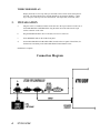
1
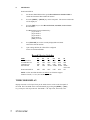
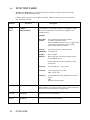
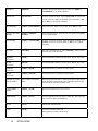
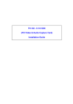
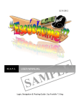
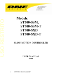
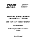
12843 Foothill Blvd., Suite D Sylmar, CA 91342 818 898 3380 voice 818 898 3360 fax www.dnfcontrols.com Model No. ST200-S/SM SLOW MOTION CONTROLLER USER MANUAL 1 ST200-S/SM Table of Contents 1. REVISION HISTORY 3 2. DESCRIPTION 3 FEATURES 3 DEFINITIONS 3 TIMECODE DISPLAY 4 3. INSTALLATION 4 4. SETUP MENU 4 4. SETUP MENU 5 5. OPERATION 6 RECORD MODE SELECTION 6 TIMECODE DISPLAY 7 6. FUNCTION TABLE 8 7. SPECIFICATIONS 11 FRONT PANEL 11 REAR PANEL 11 EXTERNAL INTERFACE CONNECTOR (GPI) DB15F 11 REAL-TIME STATUS INDICATORS - ACTIVE ON 12 RS422 SERIAL CONNECTOR 12 RECORD SELECTOR SWITCHES 12 8. TOP VIEW / REAR VIEW 13 9. DNF CONTROLS LIMITED WARRANTY 14 Manual Version................…......................... 2.11 102506 Document No.................ST200-SSM_User_Manual.doc 2 ST200-S/SM 1. 2. REVISION HISTORY 010504 Rev. 2.1 Company header information revised. Added DNF Controls Limited Warranty. 102506 Rev. 2.11 Added Timecode select function. DESCRIPTION High–quality, low-cost Slow Motion Controller. Wheel for fast and easy Slo-mo operation: 0-200% or –100% to +200% of Play speed. Quickly and easily store and recall 100 Cue Points. All Cue Points are retained when power is off. Small, space saving desktop unit, simple and easy to use. FEATURES Powerful setup menu. Configure the Slow Motion Controller for the way you work. Small footprint, fits almost anywhere - even in your lap! Quickly and easily store and recall up to 100 Cue Points. Press 1 key to mark Cue Point. Press 2 keys to recall 100 Cue Points. Fast and easy to search to a Cue Point or a manually entered Timecode number. Manually enter/edit Cue Points. Set Preroll duration from one frame to one hour. 2-Line by 16-Character Display. Freeze on last good video (Record Out point). DEFINITIONS 3 Throughout this document VTR, DDR, VDR & Video Server will be referred to collectively as “Video Server.” The ST200-S/SM as the ST200. Words surrounded by brackets, for example, [ENTER], are keys on the ST200. [XXX] + [XXX] means hold the two keys down simultaneously. ‘Q’ means Time Code Cue Point. ST200-S/SM TIMECODE DISPLAY Display timecode or CTL Tape Timer per the mode selector switch on the front panel of the VTR. The Time Mode can be selected manually by pressing the [SHIFT] + [JOG] keys, each press will step to the next Time Mode: CTL Tape Time, Timecode, VITC. 3. INSTALLATION a. Plug one end of a 9-conductor, RS422 serial cable in to the 9-pin connector on the rear of the SLOW MOTION CONTROLLER. Plug the other end of the cable into the 9-pin remote connector on the VTR. b. Plug the POWER SUPPLY into a wall outlet, 90 VAC TO 240 VAC. c. Select REMOTE mode on the VTR's front panel. d. Set the RECORD SELECTOR SWITCHES, located on the rear panel of the ST200, for the desired record mode per the "RECORD SELECTOR CHART" below. Installation is complete. Connection Diagram 4 ST200-S/SM 4. SETUP MENU Press [SHIFT] + [SETUP MENU] to enter Setup Menu. Turn WHEEL to select Mode to change. Press [DEL] to toggle between available modes of operation. Press [ESC] at any time to save changes and exist. MENU MODES RECORD MODE CLEAR MEMORY 5 (Turning Wheel Clockwise) Select the desired record mode: Lockout, Assemble, Crash/Full or Insert. Only in INSERT mode, press ‘LTC” to toggle Video record on off, [1] for Audio1, [2] for Audio2, [3] for Audio3 and [4] for Audio 4. Press [5] to clear the Cue Point memory to 00:00:00:00 SLOMO Static or Update. Static retains preset slo mo speed when exiting slo mo PRESET speed. Update retains latest slo mo speed when exiting slo mo mode. GOTO-Q Go to Q point and . . . Play or Still. SLO-MO Select speed range: 0 Æ +200 OR -100 Æ +200. MARK-Q Enable/Disable automatic ADVANCE to next Cue Point OR remain at current Q point. ST200-S/SM 5. OPERATION Select the desired transport function by pressing the appropriate switch on the front of the SLOW MOTION CONTROLLER. The Real-Time Status Indicators will light to indicate the VTR's current tape transport mode. For example - Pressing [PLAY] will put the VTR into the PLAY mode. The PLAY Status Indicator will turn on when the VTR is in PLAY mode. NOTE: The VTR will not go into Record mode if "Record Inhibit" is enabled on the VTR or tape cassette. Loss of serial communication with the VTR is indicated by ALL bottom row status LEDs turned ON. The top line of the display will show "VTR COMM ERROR." Check all cabling and connections between the VTR and ST200. Selecting LOCAL control on the VTR's from panel will turn OFF all bottom row status LEDs. RECORD MODE SELECTION Four (4) Record modes are available: Crash Record (Full Record), Assemble Record, Insert Record and Record Lockout. The ST200 offers 2 methods of selecting the desired RECORD MODE: Rear Panel DIP switches OR Front Panel SETUP. a. METHOD #1 Rear Panel DIP Switches. This method allows selection of the RECORD MODE using the Rear Panel DIP Switches. Set the DIP Switches per the following Record Selector Switches Table. NOTE- Any attempts to change the RECORD MODE from the Front Panel SETUP function will be inhibited. 6 ST200-S/SM b. METHOD #2 Front Panel SETUP 1) Set the Rear Panel DIP Switches per the Record Selector Switches Table to enable the Front Panel Record SETUP function. 2) Press the [SHIFT] + [SETUP] key on the front panel. The current record mode will be displayed. 3) Press the [DEL] key to select Record Lockout, Assemble, Crash or Insert Record modes. For Insert selection, Press Number Key: [1] for Audio 1. [2] for Audio 2. [3] for Audio 3. [4] for Audio 4. [LTC] for Video. 4) Press [ESCAPE] to save the currently displayed Record mode and exit the SETUP function. 5) Upon exiting SETUP, the VTR will be configured for the selected Record Mode. Record Selector Switches Mode Record Lockout Assemble Record Crash Record Insert Record S1 OFF ON OFF ON S2 OFF OFF ON VID S3 OFF OFF OFF AUD1 S4 OFF OFF OFF AUD2 S5 OFF OFF OFF AUD3 Front Panel SETUP OFF OFF OFF OFF OFF S6 OFF OFF OFF AUD4 Active ON ON NOTE: AUD3 & AUD4 should be ON ONLY for VTRs that support channels of audio, i.e.: D1-, D2- and D3-type VTRs. TIMECODE DISPLAY Display timecode or CTL Tape Timer per the mode selector switch on the front panel of the VTR. The Time Mode can be selected manually by pressing the [SHIFT] + [JOG] keys, each press will step to the next Time Mode: CTL Tape Time, Timecode, VITC. 7 ST200-S/SM 6. FUNCTION TABLE NOTE- Check SETUP prior to using the Slow Motion Controller to confirm proper Record mode, SLO-MO speed range and Mark-Q mode. Lettering on the top panel is color-coded as to function. White is a Function; Yellow is the Number Keys and Orange is Setup. Function SETUP MENU Key Press [SHIFT] + [SETUP MENU] Description Turn WHEEL to select Mode to change. Press [DEL] to toggle between available modes of operation. Press [ESC] to save changes and exit. MODES: RECORD MODE Select the desired record mode: Lockout, Assemble, Crash/Full or Insert. Only in INSERT mode, press ‘LTC” to toggle Video record on off, [1] for Audio1, [2] for Audio2, [3] for Audio3 and [4] for Audio 4. CLEAR MEMORY Press [5] to clear the Cue Point memory to 00:00:00:00 SLOMO PRESET Static or Update. Static retains preset slo-mo speed when exiting slo-mo PRESET Speed. Update retains latest slo-mo speed when exiting slo-mo mode. GOTO-Q Go to Q point and . . . Play or Still. SLO-MO Select speed range: 0 Æ +200 OR –100 Æ +200. MARK-Q Enable/Disable automatic ADVANCE to next Cue Point. OR Remain at current Q point. MARK-Q [MARK-Q] Save the current time in the currently displayed Cue Point. Per SETUP MENU, (see SETUP Function), the Cue Point will advance to the next Cue Point location or remain the same. NEXT-Q [NEXT-Q] Step to the next Cue Point number. LAST-Q [LAST-Q] Step to the previous Cue Point number. 8 ST200-S/SM PREROLL [PREROL] Preroll to the currently displayed Cue Point. Use [SHIFT] + [SETPREROL] to set the Preroll value. GOTO CUE [GOTO CUE] Goto the entered Cue Point. Press [GOTO CUE] to search to the current Cue Point. OR enter the 2-digit Cue Point number. OR press [ESC] to exit without searching. SET PREROLL [SHIFT] +[ SET PREROL] Set Preroll value. Enter 0 to 9 seconds. Press [ESC] to exit. PRESET SLO-MO SPEED [SHIFT] + [PRESET SLOMO] Preset SLO-MO Speed. Turn wheel to select speed. Press [ESC] to save speed and exit. GOTO TIME [SHIFT] + [GOTO TIME] Goto the entered time location. Enter desired time location. Press [GOTO] to search to the entered time or [ESC] to exit without searching. SLO-MO [SLO-MO] Vary play speed using wheel. Press [SLO-MO] to STILL frame. Press any key to exit SLO-MO. REWIND (4x PLAY) [RWD] Press and HOLD to shuttle at 4x play speed. Release key to stop. FFWD (4x PLAY) [FFWD] Press and HOLD to shuttle at 4x play speed. Release key to stop. REWIND (8x PLAY) [SHIFT] + [RWD] Press and release key to shuttle at 8x play speed. FFWD (8x PLAY) [SHIFT] + [FFWD] Press and release key to shuttle at 8x play speed. FREEZE ON LAST GOOD VIDEO Active ONLY in SLO-MO mode. When the current timecode is 6 frames before the last Record Out point (memorized automatically upon exiting Record mode), the SLO-MO mode will abort to STILL mode. TAPE TIMER RESET [SHIFT] + [STOP] Reset the control track tape timer, Timer1. TIME MODE [SHIFT] + [PLAY] Press to toggle between Tape Time or Timecode. This selects the time source for display and MARK-Q. PLAY [PLAY] Places VTR in PLAY mode. STOP [STOP] Press once to STILL frame VTR. Press again to put VTR in STOP mode. 9 ST200-S/SM JOG/SHUTTLE [JOG] Press to toggle between JOG and SHUTTLE modes. The Jog/Shuttle wheel is active when the VTR is in Stop or Still mode. The JOG status indicator will turn on when JOG mode is active. RECORD [REC] Places VTR in the Record mode selected by RECORD MODE in the SETUP MENU. (See SETUP MENU.) One-button record. 10 ST200-S/SM 7. SPECIFICATIONS FRONT PANEL 6 Status LEDs 1 Power LED 3 Direction LEDs Switches Display Jog/Shuttle Wheel Size Weight Record, Play, Stop, Rewind, FFwd, Jog, Slo Mo Indicates direction of Jog Shuttle Record, Play, Stop, Rewind, Fast Forward, Jog, Shift, Reset 2-Line LCD, back lit with adjustable contrast 8 ½” x 5 ½” x 2 ½” 4lbs. REAR PANEL DIP Switches LCD Contrast adjust Reset Ground Terminal RS422 Serial Out Power: GPI RECORD MODE: Lockout, Crash, Insert, Assemble 9-Pin D-type connector, female (DB9-F) 9-Pin D-type connector, male (DB9M) 5 volt D.C., 1 A. 90-265 VAC, 50/60 Hz converter supplied 15-pin D-type connector, female (DB15F) Switch Input: SPST contact closure, momentary Status Output: Open collector, sink 50mA. EXTERNAL INTERFACE CONNECTOR (GPI) DB15F PIN FUNCTION 1 2 3 4 5 6 7 8 9 10 11 12 14 15 +5v DC SHIFT Switch Record Tally Play Tally Stop/Still Tally Rewind/ Reverse Tally Fast Forward/ Forward Tally Jog Tally Command Common Record Command Play Command Stop Command Fast Forward Command Jog/Shuttle Select Command NOTE Active Low Active Low, Open-Collector Active Low, Open-Collector Active Low, Open-Collector Active Low, Open-Collector Active Low, Open-Collector Active Low, Open-Collector Active Low Active Low Active Low Active Low Active Low NOTE: There are no internal current limiting resistors for the open-collector Tally Outputs. Limit each Tally Output current to 40ma. 11 ST200-S/SM REAL-TIME STATUS INDICATORS - ACTIVE ON Bottom Row of Keypad LEDs #1 2 3 4 5 6 RECORD PLAY STOP/STILL REWIND/REVERSE FAST FORWARD/FORWARD JOG MODE RS422 SERIAL CONNECTOR 9-Pin D-Type, Female Pin # 1 2 3 4 5 6 7 8 9 Frame Ground Receive AÍ Transmit B Î Transmit Common Spare Receive Common Receive B Í Transmit A Î Frame Ground RECORD SELECTOR SWITCHES Mode Record Lockout OFF Assemble Record ON Crash Record Insert Record Front Panel SETUP 12 ST200-S/SM S1 OFF OFF OFF ON OFF S2 OFF OFF ON VID OFF S3 OFF OFF OFF AUD1 OFF S4 OFF OFF OFF AUD2 OFF S5 OFF OFF OFF AUD3 OFF S6 OFF AUD4 - Active ON ON 8. TOP VIEW / REAR VIEW Top View Rear View 13 ST200-S/SM 9. DNF CONTROLS LIMITED WARRANTY DNF Controls warrants its product to be free from defects in material and workmanship for a period of one (1) year from the date of sale to the original purchaser from DNF Controls. In order to enforce the rights under this warranty, the customer must first contact DNF’s Customer Support Department to afford the opportunity of identifying and fixing the problem without sending the unit in for repair. If DNF’s Customer Support Department cannot fix the problem, the customer will be issued a Returned Merchandise Authorization number (RMA). The customer will then ship the defective product prepaid to DNF Controls with the RMA number clearly indicated on the customer’s shipping document. The merchandise is to be shipped to: DNF Controls 12843 Foothill Blvd., Suite D Sylmar, CA 91342 USA Failure to obtain a proper RMA number prior to returning the product may result in the return not being accepted, or in a charge for the required repair. DNF Controls, at its option, will repair or replace the defective unit. DNF Controls will return the unit prepaid to the customer. The method of shipment is at the discretion of DNF Controls, principally UPS Ground for shipments within the United States of America. Shipments to international customers will be sent via air. Should a customer require the product to be returned in a more expeditious manner, the return shipment will be billed to their freight account. This warranty will be considered null and void if accident, misuse, abuse, improper line voltage, fire, water, lightning or other acts of God damaged the product. All repair parts are to be supplied by DNF Controls, either directly or through its authorized dealer network. Similarly, any repair work not performed by either DNF Controls or its authorized dealer may void the warranty. After the warranty period has expired, DNF Controls offers repair services at prices listed in the DNF Controls Price List. DNF Controls reserves the right to refuse repair of any unit outside the warranty period that is deemed non-repairable. DNF Controls shall not be liable for direct, indirect, incidental, consequential or other types of damage resulting from the use of the product. ### 14 ST200-S/SM