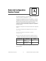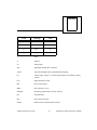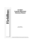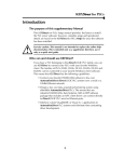
1
Intel 80188EB-Based
Fieldbus Round Card
User Manual
80188EB-Based Fieldbus Round Card User Manual
January 1998 Edition
Part Number 321019C-01
© Copyright 1996, 1998 National Instruments Corporation. All rights reserved.
Internet Support
[email protected]
E-mail: [email protected]
FTP Site: ftp.natinst.com
Web Address: http://www.natinst.com
Bulletin Board Support
BBS United States: (512) 794-5422
BBS United Kingdom: 01635 551422
BBS France: 01 48 65 15 59
Fax-on-Demand Support
(512) 418-1111
Telephone Support (U.S.)
Tel: (512) 795-8248
Fax: (512) 794-5678
International Offices
Australia 03 9879 5166, Austria 0662 45 79 90 0, Belgium 02 757 00 20, Brazil 011 288 3336,
Canada (Ontario) 905 785 0085, Canada (Québec) 514 694 8521, Denmark 45 76 26 00,
Finland 09 725 725 11, France 01 48 14 24 24, Germany 089 741 31 30,
Hong Kong 2645 3186, Israel 03 6120092, Italy 02 413091, Japan 03 5472 2970,
Korea 02 596 7456, Mexico 5 520 2635, Netherlands 0348 433466, Norway 32 84 84 00,
Singapore 2265886, Spain 91 640 0085, Sweden 08 730 49 70, Switzerland 056 200 51 51,
Taiwan 02 377 1200, United Kingdom 01635 523545
National Instruments Corporate Headquarters
6504 Bridge Point Parkway
Austin, TX 78730-5039
Tel: (512) 794-0100
Important Information
Warranty
The Fieldbus Round Card is warranted against defects in materials and workmanship for a period of one year from the
date of shipment, as evidenced by receipts or other documentation. National Instruments will, at its option, repair or
replace equipment that proves to be defective during the warranty period. This warranty includes parts and labor.
The media on which you receive National Instruments software are warranted not to fail to execute programming
instructions, due to defects in materials and workmanship, for a period of 90 days from date of shipment, as evidenced
by receipts or other documentation. National Instruments will, at its option, repair or replace software media that do
not execute programming instructions if National Instruments receives notice of such defects during the warranty
period. National Instruments does not warrant that the operation of the software shall be uninterrupted or error free.
A Return Material Authorization (RMA) number must be obtained from the factory and clearly marked on the outside
of the package before any equipment will be accepted for warranty work. National Instruments will pay the shipping
costs of returning to the owner parts which are covered by warranty.
National Instruments believes that the information in this manual is accurate. The document has been carefully
reviewed for technical accuracy. In the event that technical or typographical errors exist, National Instruments reserves
the right to make changes to subsequent editions of this document without prior notice to holders of this edition. The
reader should consult National Instruments if errors are suspected. In no event shall National Instruments be liable for
any damages arising out of or related to this document or the information contained in it.
EXCEPT AS SPECIFIED HEREIN, NATIONAL INSTRUMENTS MAKES NO WARRANTIES, EXPRESS OR IMPLIED, AND
SPECIFICALLY DISCLAIMS ANY WARRANTY OF MERCHANTABILITY OR FITNESS FOR A PARTICULAR PURPOSE .
CUSTOMER’S RIGHT TO RECOVER DAMAGES CAUSED BY FAULT OR NEGLIGENCE ON THE PART OF NATIONAL
INSTRUMENTS SHALL BE LIMITED TO THE AMOUNT THERETOFORE PAID BY THE CUSTOMER. NATIONAL INSTRUMENTS
WILL NOT BE LIABLE FOR DAMAGES RESULTING FROM LOSS OF DATA, PROFITS, USE OF PRODUCTS, OR INCIDENTAL OR
CONSEQUENTIAL DAMAGES, EVEN IF ADVISED OF THE POSSIBILITY THEREOF . This limitation of the liability of National
Instruments will apply regardless of the form of action, whether in contract or tort, including negligence. Any action
against National Instruments must be brought within one year after the cause of action accrues. National Instruments
shall not be liable for any delay in performance due to causes beyond its reasonable control. The warranty provided
herein does not cover damages, defects, malfunctions, or service failures caused by owner’s failure to follow the
National Instruments installation, operation, or maintenance instructions; owner’s modification of the product;
owner’s abuse, misuse, or negligent acts; and power failure or surges, fire, flood, accident, actions of third parties,
or other events outside reasonable control.
Copyright
Under the copyright laws, this publication may not be reproduced or transmitted in any form, electronic or mechanical,
including photocopying, recording, storing in an information retrieval system, or translating, in whole or in part,
without the prior written consent of National Instruments Corporation.
Trademarks
NI-FBUS™ is a trademark of National Instruments Corporation.
Product and company names listed are trademarks or trade names of their respective companies.
WARNING REGARDING MEDICAL AND CLINICAL USE OF NATIONAL INSTRUMENTS PRODUCTS
National Instruments products are not designed with components and testing intended to ensure a level of reliability
suitable for use in treatment and diagnosis of humans. Applications of National Instruments products involving
medical or clinical treatment can create a potential for accidental injury caused by product failure, or by errors on the
part of the user or application designer. Any use or application of National Instruments products for or involving
medical or clinical treatment must be performed by properly trained and qualified medical personnel, and all traditional
medical safeguards, equipment, and procedures that are appropriate in the particular situation to prevent serious injury
or death should always continue to be used when National Instruments products are being used. National Instruments
products are NOT intended to be a substitute for any form of established process, procedure, or equipment used to
monitor or safeguard human health and safety in medical or clinical treatment.
Contents
About This Manual
How to Use the Manual Set .......................................................................................... vii
Organization of This Manual ........................................................................................ viii
Conventions Used in This Manual................................................................................ viii
Related Documentation................................................................................................. ix
Customer Communication ............................................................................................ ix
Chapter 1
Introduction
What You Need to Get Started ..................................................................................... 1-1
Hardware Overview ...................................................................................................... 1-1
Software Overview ....................................................................................................... 1-2
Chapter 2
Hardware Installation
Install the Hardware...................................................................................................... 2-1
Chapter 3
Software Installation
Fieldbus Round Card Interface Kit Components.......................................................... 3-1
Install the Software ....................................................................................................... 3-1
Chapter 4
Interfacing to Your Round Card
Interfacing to the Hardware .......................................................................................... 4-1
Using the Software........................................................................................................ 4-2
Overview ........................................................................................................ 4-2
Developing Your Round Card Application.................................................... 4-2
Writing Device Templates ............................................................... 4-3
Converting a Device Template to C Code ....................................... 4-3
Writing Function Block Callbacks................................................... 4-4
Writing userStart and Registering Callbacks ................................... 4-4
© National Instruments Corporation
v
80188EB-Based Fieldbus Round Card User Manual
Contents
Generating Your Device Configuration........................................... 4-5
Converting Your Device Configuration to C Code ......................... 4-5
Compiling, Linking, and Locating Your Program .......................... 4-5
Burn Your Flash .............................................................................. 4-7
Appendix A
Data Link Configuration Section Format
Appendix B
System Management Configuration Section Format
Appendix C
Specifications
Appendix D
Customer Communication
Glossary
Figures
Figure 2-1.
Figure 2-2.
Top Side of 80188EB-Based Fieldbus Round Card.............................. 2-2
Bottom Side of 80188EB-Based Fieldbus Round Card ........................ 2-3
Tables
Table 4-1.
Memory Map of Round Card ................................................................ 4-7
Table A-1.
Valid Variable Names and Values for the Data Link Configuration .... A-1
Table B-1.
Table B-2.
Valid Variable Names and Values for the MIB Sections...................... B-2
Valid Variable Names and Values for the FB Schedule Sections......... B-2
Table C-1.
Table C-2.
Fieldbus Round Card Specifications ..................................................... C-1
Fieldbus Round Card Components........................................................ C-1
80188EB-Based Fieldbus Round Card User Manual
vi
© National Instruments Corporation
About
This
Manual
This manual contains instructions for installing, interfacing to, and
programming the National Instruments Fieldbus Round Card. The
Round Card software is intended for use with Windows 3.x,
Windows 95, or Windows NT.
This manual assumes that you are already familiar with the Windows
operating system you are using.
How to Use the Manual Set
Use the Getting Started with Fieldbus manual to install and configure
your Fieldbus hardware, the Fieldbus Stack Interface Library, and the
NI-FBUS Function Block Shell software.
Use this Intel 80188EB-Based Fieldbus Round Card User Manual
manual to install the Intel 80188EB-based Fieldbus Round Card.
Use the MC68331-Based Fieldbus Round Card User Manual to install
the Motorola MC68331-based Fieldbus Round Card.
Use the NI-FBUS Function Block Shell Reference Manual to learn
about writing Function Block server applications that are embedded in
the Fieldbus Round card.
Use the NI-FBUS Monitor User Manual to learn to use the interactive
NI-FBUS Monitor utility with your Fieldbus Round Card.
Use the NI-FBUS Communications Manager User Manual to learn to
use the interactive Fieldbus dialog system with your Fieldbus Round Card.
Use the NI-FBUS Configurator User Manual to learn to use the
NI-FBUS Configurator to configure your Fieldbus network.
© National Instruments Corporation
vii
80188EB-Based Fieldbus Round Card User Manual
About This Manual
Organization of This Manual
This manual is organized as follows:
•
Chapter 1, Introduction, lists what you need to get started and
includes a brief description of the Fieldbus Round Card hardware
and supplied software.
•
Chapter 2, Hardware Installation, contains instructions to help you
install your Fieldbus Round Card.
•
Chapter 3, Software Installation, contains instructions for
installing the software that came with your Fieldbus Round Card.
•
Chapter 4, Interfacing to Your Round Card, describes how to
connect the Fieldbus Round Card to any external electronics, and
how to develop your Field Device application to interface to the
NI-FBUS Function Block Shell.
•
Appendix A, Data Link Configuration Section Format, explains
how to structure the Data Link Configuration section of your
Device Configuration .ini file.
•
Appendix B, System Management Configuration Section Format,
explains how to structure the System Management Configuration
section of your Device Configuration .ini file.
•
Appendix C, Specifications, describes the characteristics of the
Fieldbus Round Card.
•
Appendix D, Customer Communication, contains forms you can
use to request help from National Instruments or to comment on our
products and manuals.
Conventions Used in This Manual
The following conventions are used in this manual:
<>
Angle brackets enclose the name of a key on the keyboard—for
example, <shift>. Angle brackets containing numbers separated by an
ellipsis represent a range of values associated with a bit or signal
name—for example, DBIO<3..0>.
This icon to the left of bold italicized text denotes a note, which alerts
you to important information.
This icon to the left of bold italicized text denotes a warning, which advises
you of precautions to take to avoid being electrically shocked.
80188EB-Based Fieldbus Round Card User Manual
viii
© National Instruments Corporation
About This Manual
bold
Bold text denotes the names of menus, menu items, parameters, dialog
box, dialog box buttons or options, icons, windows, Windows 95 tabs,
or LEDs.
bold italic
Bold italic text denotes a note, caution, or warning.
italic
Italic text denotes emphasis, a cross reference, or an introduction to a
key concept. This font also denotes text from which you supply the
appropriate word or value, as in Windows 3.x.
italic monospace
Italic text in this font denotes that you must supply the appropriate
words or values in the place of these items.
monospace
Text in this font denotes text or characters that you should literally enter
from the keyboard, sections of code, programming examples, and
syntax examples. This font is also used for the proper names of disk
drives, paths, directories, programs, subprograms, subroutines, device
names, functions, operations, variables, filenames and extensions, and
for statements and comments taken from programs.
Related Documentation
The following document contains information that you may find helpful
as you read this manual:
•
Fieldbus Foundation Specification, which includes the following
items:
–
Fieldbus Foundation System Management Services
–
Function Block Application Process, Part 1
–
Function Block Application Process, Part 2
Customer Communication
National Instruments wants to receive your comments on our products
and manuals. We are interested in the applications you develop with our
products, and we want to help if you have problems with them. To make
it easy for you to contact us, this manual contains comment and
configuration forms for you to complete. These forms are in
Appendix D, Customer Communication, at the end of this manual.
© National Instruments Corporation
ix
80188EB-Based Fieldbus Round Card User Manual
Chapter
1
Introduction
This chapter lists what you need to get started and includes a brief
description of the Fieldbus Round Card hardware and supplied
software.
What You Need to Get Started
To install your Fieldbus Round Card Interface Kit, you need the
following items:
•
Fieldbus Round Card
•
Fieldbus Round Card Interface Kit distribution disk
•
Windows 3.x, Windows 95, or Windows NT installed on your
computer
Hardware Overview
The Fieldbus Round Card is a stand-alone card that allows you to
interface to a network that complies with the Fieldbus Foundation H1
specification. The Fieldbus Round Card uses the Intel 80188EB
embedded processor and a programmable 256 KB × 8 Flash to run the
Stack Interface Library, Function Block Shell, and user applications. A
128 KB × 8 SRAM device on the card provides volatile memory.
The Intel 80188EB processor supports two serial ports. You can use one
serial port as a debug port and connect it to the COM port of the host
running the debugger software. A typical application for the other serial
port would be to interface to a device running the serial HART protocol
or other proprietary serial protocol. Both serial ports provide
3 V-compatible signals. The Fieldbus Round Card is capable of
providing a 3.9 V at 8 mA power supply to power your electronics. The
serial ports and the 3.9 V output are accessible from a 2 × 4 female
connector.
© National Instruments Corporation
1-1
80188EB-Based Fieldbus Round Card User Manual
Chapter 1
Introduction
The Fieldbus Round Card operates under one of two modes: PROG
mode and RUN mode. To select PROG mode, place jumper B on the
card. To select RUN mode, remove jumper B from the card.
When power is applied to the Fieldbus Round Card, the processor reads
the position of jumper B of W1 to check the mode. When the card is in
PROG mode, you can download your application from the COM port of
the host computer connected to the debug serial port. When the card is
in RUN mode, the processor begins executing the application that is
loaded in the Flash.
Software Overview
The software supplied with the Fieldbus Round Card Interface Kit
includes the NI-FBUS Function Block Shell, which is an Application
Programmer’s Interface (API) designed to simplify Fieldbus device
development by providing a high-level interface to the Fieldbus
communications stack. In addition, you can use the serial driver API to
make use of the Round Card’s interrupt-driven serial port. The serial
driver supports standard HART commands, as well as generic access to
the serial port to allow any other serial protocols. A linkable library
version of the Fieldbus protocol stack is also supplied. Link your
Function Block application with the Function Block Shell and the
protocol stack before downloading it to your Fieldbus Round Card.
80188EB-Based Fieldbus Round Card User Manual
1-2
© National Instruments Corporation
Chapter
Hardware Installation
2
This chapter contains instructions to help you install your Fieldbus
Round Card.
Warning: Several components on your Fieldbus Round Card can be damaged by
electrostatic discharge. To avoid such damage in handling the board, touch
the antistatic plastic package to a metal part of your computer chassis
before removing the board from the package.
Install the Hardware
Perform the following steps to install the Fieldbus Round Card.
1.
Connect the Fieldbus cable to terminal J2 (see Figure 2-1) on the
Round Card. The positive (+) end of the cable should be connected
to terminal 0A and the negative (–) end of the cable should be
connected to terminal 1A . Ensure that the Fieldbus cable is
properly terminated.
2.
Press the reset button on the Round Card, S1 (see Figure 2-1), to
reset the processor.
© National Instruments Corporation
2-1
80188EB-Based Fieldbus Round Card User Manual
Chapter 2
Hardware Installation
U1
LED
U2
S1
Reset
Button
J2
3IN GND
W
A
B
U5
1
Y1
Mode
Configuration
IA 0A
Figure 2-1. Top Side of 80188EB-Based Fieldbus Round Card
In Figure 2-2, W2 shows the pinout of the user electronics connector,
and U9 shows where your Flash should be placed after burning.
Chapter 4, Interfacing to Your Round Card, describes the signals on the
user electronics connector and explains how to burn your Flash.
80188EB-Based Fieldbus Round Card User Manual
2-2
© National Instruments Corporation
Chapter 2
Hardware Installation
U6
U7
C13
C12
Flash
U8
U9
Pin 1
U11
3O
3I
C20
W2
3VOUT
DOUT
DIN
GND
Figure 2-2. Bottom Side of 80188EB-Based Fieldbus Round Card
Your hardware is now installed. Proceed to Chapter 3, Software
Installation, for instructions on installing the software.
© National Instruments Corporation
2-3
80188EB-Based Fieldbus Round Card User Manual
Chapter
3
Software Installation
This chapter contains instructions for installing the software that came
with your Fieldbus Round Card.
Fieldbus Round Card Interface Kit Components
The Fieldbus Round Card Interface Kit contains the following software
components:
•
Function Block Shell Code Generation and Configuration
Generation utilities for Windows
•
Combined protocol stack, NI-FBUS Function Block Shell, and
Serial Driver linkable library for Borland C/C++ 4.5
•
Sample function block templates for all standard Foundation
Fieldbus function blocks
•
Sample function block configuration files
•
C language header files for interfacing to the NI-FBUS Function
Block Shell
Install the Software
Complete the following steps to run the software installation program.
1.
Insert the Fieldbus Round Card Interface Kit distribution disk into
an unused drive.
2.
Windows 95 or Windows NT 4.x: Choose Run... from the Start
menu.
Windows 3.x or Windows NT 3.5 or earlier: Choose Run... from
the File menu in the Program Manager window.
3.
Type the following command into the dialog box that appears:
x:\setup
where x is the letter of the drive containing the distribution disk
(usually a or b).
© National Instruments Corporation
3-1
80188EB-Based Fieldbus Round Card User Manual
Chapter 3
Software Installation
4.
The interactive installation program installs the software into the
directory of your choice.
Your software installation is now complete. Proceed to Chapter 4,
Interfacing to Your Round Card.
80188EB-Based Fieldbus Round Card User Manual
3-2
© National Instruments Corporation
Chapter
Interfacing to Your
Round Card
4
This chapter describes how to connect the Fieldbus Round Card to any
external electronics, and how to develop your Field Device application
to interface to the NI-FBUS Function Block Shell.
Interfacing to the Hardware
The 2 × 4 female connector on the bottom side of the Fieldbus Round
Card, W2, is a user electronics connector that contains signals you can
connect to any user-supplied electronics. There are three sets of signals:
3VOUT, Serial Port 0, and Serial Port 1.
The three sets of signals have a common ground pin. See the W2 item
in Figure 2-2, Bottom Side of 80188EB-Based Fieldbus Round Card, in
Chapter 2, Hardware Installation, for the pinout of the user electronics
connector.
The signals are described as follows:
•
3VOUT—The Fieldbus Round Card has a 3.9 V at 8 mA output
that you can use to power the user electronics.
To activate the 3.9 V output on the W2 connector of the Round
Card, place a 0 Ω resistor on R18 and replace R35 with a 0 Ω
resistor. Doing this increases the current draw from the Fieldbus to
32 mA in the quiescent state. R18 and R35 are located on the
bottom side of the Round Card.
•
Serial Port 0—The Transmit and Receive pins of the
microprocessor serial port 0 are available at the user electronics
connector. You can use this port as an asynchronous serial link to
the user electronics board. This port can perform interrupt-driven
serial communication. The 3O pin is the Transmit pin and the 3I pin
is the Receive pin. Both of these pins provide 3 V-compatible
signals.
•
Serial Port 1—The Transmit and Receive pins of the processor
serial port 1 are available at the user electronics connector. This
port cannot perform interrupt-driven serial communication. The
© National Instruments Corporation
4-1
80188EB-Based Fieldbus Round Card User Manual
Chapter 4
Interfacing to Your Round Card
DOUT pin is the Transmit pin and the DIN pin is the Receive pin
of serial port 1. Both of these pins provide 3 V compatible signals.
You can use this port as a debugger port to debug your application.
To interface to the COM ports on a host PC computer running a
debugger, you should provide means to convert these Fieldbus
signals to RS-232 format.
Using the Software
Overview
Most of the code that will be running on your Fieldbus Round Card has
already been written for you. It includes the Fieldbus protocol stack,
Function Block Shell, and Serial Driver, which are provided in the form
of a linkable library with your Fieldbus Round Card Interface Kit. This
library provides Fieldbus communications and an API (the Function
Block Shell) designed to isolate your application as much as possible
from the specifics of the Fieldbus. For more specific information about
the Function Block Shell API, consult the NI-FBUS Function Block
Shell Reference Manual.
In addition, the library contains an API to allow HART or direct serial
access to the Round Card’s serial port. This API facilitates
communications with a HART or serial transducer external to the
Round Card. This Serial Driver API is also described in Chapter 8,
Serial Functions, of the NI-FBUS Function Block Shell Reference
Manual.
Developing Your Round Card Application
Complete the following steps to develop your application, after you
have installed the hardware and software:
1.
Write a device template for your device.
2.
Convert the device template to C code using the Device Code
Generator.
3.
Write your Function Block Callbacks, algorithms, and device
interface code.
4.
Write your userStart function to register your callbacks.
5.
Write your Device Configuration.
6.
Convert your Device Configuration to C code using the
Configuration Code Generator.
80188EB-Based Fieldbus Round Card User Manual
4-2
© National Instruments Corporation
Chapter 4
Interfacing to Your Round Card
7.
Compile, link, and locate your program on EPROM for installation
on the Round Card.
8.
Burn your EPROM and place it at U9 on the Round Card. See
Figure 2-2, Bottom Side of 80188EB-Based Fieldbus Round Card,
in Chapter 2, Hardware Installation.
These steps are documented in more detail in the following sections.
Writing Device Templates
You must create a device template to describe the network-visible
structure of your device and the parameters of your function blocks
to the Function Block Shell. The device template is an ASCII file
that is divided into various sections containing numerical and string
parameters. The \samples subdirectory of your installation directory
contains sample device templates for devices containing function
blocks of the standard types.
The simplest way to create your device template is to modify a copy of
one of the sample device templates using a text editor such as MS-DOS
Edit or Windows Notepad. Choose the sample device template that most
closely matches your device. For example, if the main function of your
device is analog input, start with the AI Device Template. If you want
your device to contain multiple function blocks, you need to paste
several BLOCK sections from the sample files into your device template
file.
The templates contain information about the device identification, the
physical and function blocks in the device, and the device parameters.
The device template syntax is described in Chapter 3, Registration
Functions, of the NI-FBUS Function Block Shell Reference Manual.
Your final device templates are converted to C code using the Device
Code Generator, described in the next section.
Converting a Device Template to C Code
Before you compile your Function Block device, you must convert the
device template to C code using the Device Code Generator. The
Device Code Generator resides in the \utils subdirectory of your
installation directory. The Device Code Generator takes the following
command line arguments:
codegen deviceTemplate outputFile symbolFile
© National Instruments Corporation
4-3
80188EB-Based Fieldbus Round Card User Manual
Chapter 4
Interfacing to Your Round Card
where deviceTemplate is the name of your device template file, and
outputFile is the name that you want to call the output file. Make sure
that outputFile ends in .c.
If there are syntax errors in your device template, codegen tells you
where they are. When you have corrected all syntax errors,
outputFile is created. outputFile contains code representing the
structure of your device. outputFile is used again when you compile
and link your device application.
symbolFile contains a reference to DD information for the parameters
defined in your DD and template file. If you are using only the standard
function blocks and their parameters, symbolFile is the standard
symbols file, nifb.sym, located in the \samples subdirectory. If you
have defined your own blocks or parameters, symbolFile must be set
to the output of the DD tokenizer.
Writing Function Block Callbacks
The callback functions that you must develop are responsible for the
following main functions:
•
Handling read and write requests from the network
•
Executing your function block algorithm
•
Handling alarm confirmations and acknowledgments (if you are
using alarms)
The Function Block Shell calls your execution callback whenever your
Block is scheduled to execute. This callback performs whatever
algorithm you want your function block to perform. The other
callbacks, which are called after your device sends an alarm, allow you
to perform device-specific processing upon alarm confirmations
(notifications that the alarm was received) and alarm
acknowledgments (notifications that a user has seen the alarm).
Other optional callbacks are provided for other purposes. See
Chapter 4, Callback Functions, of the NI-FBUS Function Block Shell
Reference Manual for more details.
Writing userStart and Registering Callbacks
Your userStart function is called by the stack during startup. It is
your chance to perform your own initialization tasks. userStart also
initializes the Function Block Shell and registers your callbacks with
80188EB-Based Fieldbus Round Card User Manual
4-4
© National Instruments Corporation
Chapter 4
Interfacing to Your Round Card
the Function Block Shell. See Chapter 7, Miscellaneous Functions, of
the NI-FBUS Function Block Shell Reference Manual for more details.
Generating Your Device Configuration
The initial configuration of your device includes the configuration of
items such as the starting node address, device identification, and,
optionally, the function block schedules. You must specify the
parameters in the standard Windows .ini file format in a configuration
.ini file. Sample configuration files are included in the \samples
subdirectory of your installation directory. You might want to start with
one of these files and edit it according to your needs. The entries in the
data link configuration and system management configuration sections
of your configuration .ini file are described in are described in
Appendix A, Data Link Configuration Section Format, and
Appendix B, System Management Configuration Section Format.
After you have generated your configuration .ini file, you must run the
Configuration Generator to create a C source file that contains your
configuration. This step is described in the next section, Converting
Your Device Configuration to C Code.
Converting Your Device Configuration to C Code
To convert your Device Configuration to a compilable and linkable .c
file, you must use the Configuration Generator utility. The
Configuration Generator requires the following syntax:
cfggen iniFile cFile
where iniFile is the name of your configuration file, and cFile is the
name of the C source file for the output C code. If your .ini file
contains errors, the Configuration Generator halts and informs you
where the errors are located. Otherwise, it creates a .c source file,
which you use in the final step to create your binary file.
Compiling, Linking, and Locating Your Program
The final stage of application development on the Round Card involves
creating a binary file suitable for downloading to the EPROM of the
Round Card.
Note:
The nistack.lib library file, which your code must link to, was created
with Borland C version 4.5. Use either the same compiler or a compatible
compiler to ensure that your code works correctly with nistack.lib.
© National Instruments Corporation
4-5
80188EB-Based Fieldbus Round Card User Manual
Chapter 4
Interfacing to Your Round Card
National Instruments recommends that you use Borland C version 4.5 for
maximum compatibility with our library file.
The first step in the final stage is compilation. The following files must
be successfully compiled to .obj format:
•
The .c file generated by the Device Code Generator.
•
The .c file generated by the Configuration Generator.
•
Your own .c file that contains your userStart function and your
callbacks.
You should compile the files to .obj format, using compiler options to
meet the following conditions:
•
You must use the Medium memory model (near data, far code). For
the Borland C 4.5 compiler, this option is -mm.
•
You must use the default structure alignment, which is a 2-byte
structure alignment for Borland C 4.5.
•
You must allow single-byte enumeration where possible. For the
Borland C 4.5 compiler, this option is -b-.
After you have compiled the files, you must link them with the National
Instruments Round Card library, nistack.lib. This file contains the
communications stack and Function Block Shell. You must specify the
following linker options when linking to nistack.lib:
•
Case-sensitive public and external symbols. For the Borland C 4.5
linker, this option is -c.
•
Ignore default libraries. For the Borland C 4.5 linker, this option
is -n.
•
Set the segment alignment to 16 bytes. For the Borland C 4.5 linker,
this option is -A=16.
When you have successfully completed linking your application, you
are ready to locate it in the physical address space of the Round Card.
To complete this step, you need a locator utility such as Paradigm
Systems’ locate.
Note:
The locator file must place the Data Segment so that it covers at least the
first 32 bytes of the Frontier-1 memory space. If the Data Segment is not
placed correctly, the Round Card will be unable to communicate on the
Fieldbus.
80188EB-Based Fieldbus Round Card User Manual
4-6
© National Instruments Corporation
Chapter 4
Interfacing to Your Round Card
The various hardware components on the Round Card are mapped into
processor memory. The memory locations of the EPROM, RAM, and
Frontier-1 are shown in Table 4-1.
Table 4-1. Memory Map of Round Card
Component
Size
Memory Window (hex)
SRAM
128 KB × 8
00000–1FFFF
Flash
256 KB × 8
C0000–FFFFF
Frontier-1
1 KB × 8
20000–20400*
* The Frontier-1 needs a 32-byte window for accessing its registers, but the minimum
memory window size that can be allocated is 1 kb, so the Frontier-1 registers are aliased
within this 1 kb memory space.
Burn Your Flash
After you have run the locator, you are ready to burn your Flash, place
it in the Round Card, and test your program.
The Fieldbus Round Card provides a method for you to burn the Flash
on the Round Card without an external burner device. This method
involves the use of the niBurn utility, an RS-232 port on the host, and
serial port 1 on the Round Card. This method requires you to build an
RS-232 to TTL serial converter cable to connect to the W2 connector
on the Round Card.
Complete the following steps to burn the Flash with the niBurn utility:
1.
Power up the Round Card in PROG Mode (see the Hardware
Overview section of Chapter 1, Introduction, for more information
about PROG Mode).
2.
Make sure that the user program is located at physical address
C0000, because this is the address the niBurn utility jumps to when
the board is reset in RUN mode, or when niBurn has successfully
downloaded the user program into the Flash in PROG mode.
3.
Launch niBurn. The niBurn utility is located in the NI Fieldbus
program group on the host. When you launch the niBurn utility,
it prompts you for the name of your binary file, and the COM port
to use.
© National Instruments Corporation
4-7
80188EB-Based Fieldbus Round Card User Manual
Chapter 4
Interfacing to Your Round Card
Your RS-232 to TTL cable leading to the Round Card must be
attached to the COM port you specify. See the Interfacing to the
Hardware section, earlier in this chapter, for the connections of
serial port 1 on the user electronics connector.
The niBurn utility contacts the Round Card and downloads your
program into the Flash on the Round Card. The utility informs you
when it has completed.
4.
After the application has downloaded, remove jumper B of W1
before resetting the Round Card.
80188EB-Based Fieldbus Round Card User Manual
4-8
© National Instruments Corporation
Appendix
Data Link Configuration
Section Format
A
This appendix explains how to structure the Data Link Configuration
section of your Device Configuration .ini file.
The Data Link Configuration section of your Windows .ini Device
Configuration file must be converted to C code and linked with your
application before the Round Card can communicate on the Fieldbus
network. The code generated by running this file through the
Configuration Generator automatically configures your board. When a
parameter is changed over the Fieldbus, the parameter is updated in
nonvolatile memory.
Following is a description of the format of the Data Link Configuration
section.
The first line of the Data Link Configuration section is as follows:
[Data Link]
The general line format for all other lines is as follows:
variable=value
where the valid variable names and values are defined in Table A-1
Table A-1. Valid Variable Names and Values for the Data Link Configuration
Variable Name
Valid Values
Default
devClass
BASIC
LINKMASTER
none
nodeAddress
0x10–0xfb
none
devClass indicates whether the device functions as a basic device or a
link master device.
© National Instruments Corporation
A-1
80188EB-Based Fieldbus Round Card User Manual
Appendix A
Data Link Configuration Section Format
nodeAddress is the address of the device on the Fieldbus network.
It ranges from 0x10 to 0xff. According to the Fieldbus Foundation
Specification, addresses between 0x10 and 0xf7 are fixed addresses.
A device with a fixed address can be in operational state. You will
normally configure your device to have a fixed address. Addresses
between 0xf8 and 0xfb are temporary addresses. A device with a
temporary address on the bus is eventually assigned a fixed address to
be operational. Addresses between 0xfc and 0xff are visitor addresses.
You should not assign a visitor address to your device.
A Sample Data Link Configuration section follows:
[Data Link]
; Comments are allowed on lines starting with a
; semicolon
devClass=BASIC
nodeAddress=0x20
If you specify a node address in the range 0xf8 through 0xfb, your
device may show up on the bus at any default address. You may use a
system configurator such as NI-FBUS Configurator to assign a fixed
address to your device.
80188EB-Based Fieldbus Round Card User Manual
A-2
© National Instruments Corporation
System Management
Configuration Section
Format
Appendix
B
This appendix explains how to structure the System Management
Configuration section of your Device Configuration .ini file.
The System Management Configuration section of your Windows .ini
Device Configuration file must be converted to C code and linked with
your application before the Round Card can communicate on the
Fieldbus network. The code generated by running this file through the
Configuration Generator automatically configures your card. When a
parameter is changed over the Fieldbus, the parameter is updated in
nonvolatile memory.
Following is a description of the format of the System Management
Configuration section:
The names of the sections in System Management Configuration are as
follows:
[MIB]
...
[FB Schedule 0]
...
[FB Schedule 1]
...
...
[FB Schedule N]
...
The general line format for all other lines is as follows:
variable=value
where the valid variable names and values are defined in Table B-1.
Note:
Most of the variables in Table B-1 are optional. In fact, only the devID is
required. For other variables, default values are used if other values have
not been defined in the configuration file
© National Instruments Corporation
B-1
80188EB-Based Fieldbus Round Card User Manual
Appendix B
System Management Configuration Section Format
.
Table B-1. Valid Variable Names and Values for the MIB Sections
Variable Name
Valid Values
Implied Units
Default
clockSyncInterval
0–255
seconds
10
macrocycleDuration
32-bit
unsigned
integer
1/32 ms
0x8000
primaryTimeMaster
0-255
n/a
none
devID
(ASCII string
identifier of
this device)
n/a
none
pdTag
(ASCII string
tag for this
device)
n/a
blank tag
T1
0–0xffffffff
1/32 ms
0x40000
T2
0–0xffffffff
1/32 ms
0x40000
T3
0–0xffffffff
1/32 ms
0x8000
Each [FB Schedule] section denotes a single entry in the
FB Schedule.
Table B-2. Valid Variable Names and Values for the FB Schedule Sections
Variable Name
Valid Values
Implied Units
Default
offset
32-bit
unsigned
integer
1/32 ms
none
index
0–65535
n/a
none
vfdRef
32-bit
unsigned
integer
n/a
none
80188EB-Based Fieldbus Round Card User Manual
B-2
© National Instruments Corporation
Appendix
C
Specifications
This appendix describes the characteristics of the Fieldbus Round Card.
Table C-1. Fieldbus Round Card Specifications
Characteristic
Specification
Dimensions
6.2 × 1.52 cm (2.44 × 0.6 in.)
Processor
Intel 80188EB, 8 MHz system clock
Fieldbus Interface
Fuji Electric Frontier-1, bus-powered,
31.25 kb/s
Fieldbus Power Supply
14–32 V at 20 mA at 8 MHz,
50 Ω terminated
Power Supply to External
Electronics
3.9 V at 8 mA
Table C-2. Fieldbus Round Card Components
Component
© National Instruments Corporation
Location on Round Card
Fieldbus Connection
2-position terminal block JI
3 V Output
2-position terminal block J2
Reset Switch
Switch S1
Program Mode Jumper
Jumper B on W1
C-1
80188EB-Based Fieldbus Round Card User Manual
Appendix
Customer Communication
D
For your convenience, this appendix contains forms to help you gather the information necessary to
help us solve your technical problems and a form you can use to comment on the product
documentation. When you contact us, we need the information on the Technical Support Form and the
configuration form, if your manual contains one, about your system configuration to answer your
questions as quickly as possible.
National Instruments has technical assistance through electronic, fax, and telephone systems to
quickly provide the information you need. Our electronic services include a bulletin board service,
an FTP site, a Fax-on-Demand system, and e-mail support. If you have a hardware or software
problem, first try the electronic support systems. If the information available on these systems
does not answer your questions, we offer fax and telephone support through our technical support
centers, which are staffed by applications engineers.
Electronic Services
Bulletin Board Support
National Instruments has BBS and FTP sites dedicated for 24-hour support with a collection of files
and documents to answer most common customer questions. From these sites, you can also download
the latest instrument drivers, updates, and example programs. For recorded instructions on how to use
the bulletin board and FTP services and for BBS automated information, call (512) 795-6990. You can
access these services at:
United States: (512) 794-5422
Up to 14,400 baud, 8 data bits, 1 stop bit, no parity
United Kingdom: 01635 551422
Up to 9,600 baud, 8 data bits, 1 stop bit, no parity
France: 01 48 65 15 59
Up to 9,600 baud, 8 data bits, 1 stop bit, no parity
FTP Support
To access our FTP site, log on to our Internet host, ftp.natinst.com, as anonymous and use your
Internet address, such as [email protected], as your password. The support files and
documents are located in the /support directories.
© National Instruments Corporation
D-1
80188EB-Based Fieldbus Round Card User Manual
Fax-on-Demand Support
Fax-on-Demand is a 24-hour information retrieval system containing a library of documents on a wide
range of technical information. You can access Fax-on-Demand from a touch-tone telephone at
(512) 418-1111.
E-Mail Support (currently U.S. only)
You can submit technical support questions to the applications engineering team through e-mail at the
Internet address listed below. Remember to include your name, address, and phone number so we can
contact you with solutions and suggestions.
[email protected]
Telephone and Fax Support
National Instruments has branch offices all over the world. Use the list below to find the technical
support number for your country. If there is no National Instruments office in your country, contact the
source from which you purchased your software to obtain support.
Telephone
Australia
Austria
Belgium
Brazil
Canada (Ontario)
Canada (Quebec)
Denmark
Finland
France
Germany
Hong Kong
Israel
Italy
Japan
Korea
Mexico
Netherlands
Norway
Singapore
Spain
Sweden
Switzerland
Taiwan
United Kingdom
United States
03 9879 5166
0662 45 79 90 0
02 757 00 20
011 288 3336
905 785 0085
514 694 8521
45 76 26 00
09 725 725 11
01 48 14 24 24
089 741 31 30
2645 3186
03 6120092
02 413091
03 5472 2970
02 596 7456
5 520 2635
0348 433466
32 84 84 00
2265886
91 640 0085
08 730 49 70
056 200 51 51
02 377 1200
01635 523545
512 795 8248
Fax
03 9879 6277
0662 45 79 90 19
02 757 03 11
011 288 8528
905 785 0086
514 694 4399
45 76 26 02
09 725 725 55
01 48 14 24 14
089 714 60 35
2686 8505
03 6120095
02 41309215
03 5472 2977
02 596 7455
5 520 3282
0348 430673
32 84 86 00
2265887
91 640 0533
08 730 43 70
056 200 51 55
02 737 4644
01635 523154
512 794 5678
Technical Support Form
Photocopy this form and update it each time you make changes to your software or hardware, and use
the completed copy of this form as a reference for your current configuration. Completing this form
accurately before contacting National Instruments for technical support helps our applications
engineers answer your questions more efficiently.
If you are using any National Instruments hardware or software products related to this problem,
include the configuration forms from their user manuals. Include additional pages if necessary.
Name __________________________________________________________________________
Company _______________________________________________________________________
Address ________________________________________________________________________
_______________________________________________________________________________
Fax ( ___ )___________________ Phone ( ___ ) _______________________________________
Computer brand ________________ Model ________________ Processor___________________
Operating system (include version number) ____________________________________________
Clock speed ______MHz RAM _____MB
Mouse ___yes ___no
Display adapter __________________________
Other adapters installed _______________________________________
Hard disk capacity _____MB
Brand _____________________________________________
Instruments used _________________________________________________________________
_______________________________________________________________________________
National Instruments hardware product model __________ Revision ______________________
Configuration ___________________________________________________________________
National Instruments software product ____________________________ Version ____________
Configuration ___________________________________________________________________
The problem is: __________________________________________________________________
_______________________________________________________________________________
_______________________________________________________________________________
_______________________________________________________________________________
_______________________________________________________________________________
List any error messages: ___________________________________________________________
_______________________________________________________________________________
_______________________________________________________________________________
The following steps reproduce the problem:____________________________________________
_______________________________________________________________________________
_______________________________________________________________________________
_______________________________________________________________________________
_______________________________________________________________________________
_______________________________________________________________________________
Hardware and Software Configuration Form
Record the settings and revisions of your hardware and software on the line to the right of each item.
Complete a new copy of this form each time you revise your software or hardware configuration, and
use this form as a reference for your current configuration. Completing this form accurately before
contacting National Instruments for technical support helps our applications engineers answer your
questions more efficiently.
National Instruments Products
Interrupt level of hardware __________________________________________________________
DMA channels of hardware _________________________________________________________
Base I/O address of hardware ________________________________________________________
Other Products
Computer make and model _________________________________________________________
Microprocessor ___________________________________________________________________
Clock frequency or speed ___________________________________________________________
Type of video board installed ________________________________________________________
Operating system version ___________________________________________________________
Operating system mode ____________________________________________________________
Programming language ____________________________________________________________
Programming language version ______________________________________________________
Other boards in system _____________________________________________________________
Base I/O address of other boards _____________________________________________________
DMA channels of other boards ______________________________________________________
Interrupt level of other boards _______________________________________________________
Documentation Comment Form
National Instruments encourages you to comment on the documentation supplied with our products.
This information helps us provide quality products to meet your needs.
Title:
Intel 80188EB-Based Fieldbus Round Card User Manual
Edition Date:
January 1998
Part Number:
321019C-01
Please comment on the completeness, clarity, and organization of the manual.
_______________________________________________________________________________
_______________________________________________________________________________
_______________________________________________________________________________
_______________________________________________________________________________
_______________________________________________________________________________
_______________________________________________________________________________
_______________________________________________________________________________
If you find errors in the manual, please record the page numbers and describe the errors.
_______________________________________________________________________________
_______________________________________________________________________________
_______________________________________________________________________________
_______________________________________________________________________________
_______________________________________________________________________________
_______________________________________________________________________________
_______________________________________________________________________________
Thank you for your help.
Name _________________________________________________________________________
Title __________________________________________________________________________
Company _______________________________________________________________________
Address ________________________________________________________________________
_______________________________________________________________________________
Phone ( ___ )__________________________ Fax ( ___ ) ________________________________
Mail to: Technical Publications
National Instruments Corporation
6504 Bridge Point Parkway
Austin, TX 78730-5039
Fax to:
Technical Publications
National Instruments Corporation
(512) 794-5678
Glossary
Prefix
Meanings
Value
m-
milli-
10-3
c-
centi-
10-2
k-
kilo-
10 3
M-
mega-
106
Ω
Ohms
A
Amperes
AI
Analog input
API
Application Programmer’s Interface
ASCII
American Standard Code for Information Interchange
bit
A binary digit; a digit (1 or 0) in the representation of a number in binary
notation
byte
Eight related bits of data
DD
Device Description
DMA
Direct-memory access
EPROM
Erasable programmable read-only memory
FB
Function Block
FTP
File Transfer Protocol
HART
HART Field Communications Protocol
© National Instruments Corporation
G-1
80188EB-Based Fieldbus Round Card User Manual
Glossary
hex
Hexadecimal
Hz
Hertz
I/O
Input/Output
KB
Kilobytes of memory
MB
megabytes of memory
OD
Object Dictionary
PC
Personal computer
PROM
Programmable read-only memory
RAM
Random-access memory
s
Seconds
snap
Read from the communications stack
SRAM
Serial random-access memory
TTL
Transistor-transistor logic
V
volts
VCR
Virtual Communication Relationship
VFD
Virtual Field Device
VOUT
Volt output
80188EB-Based Fieldbus Round Card User Manual
G-2
© National Instruments Corporation