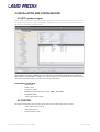
1
System manual HLS HDTV digital System Manual Rev. 1328 User manual for HDTV-D – Rev. 1328 Page 1 of 44 Table of Contents 1 Introduction ....................................................................................................................................... 5 2 HDTV-D System overview ............................................................................................................. 6 2.1 System overview................................................................................................................................................ 7 2.2 HD-TV-D Application examples ......................................................................................................................8 2.2.1 HDMI distribution - Basic system ............................................................................................................................................ 8 2.2.2 Typical HDTV-D system for retail electronic store .............................................................................................................. 9 3 System planning ............................................................................................................................ 10 3.1 General rules .................................................................................................................................................... 10 3.1.1 Limited of HDMI distribution ..................................................................................................................................................... 10 3.1.2 Power .......................................................................................................................................................................................... 10 3.1.3 HDMI Cables ............................................................................................................................................................................... 11 3.1.4 CAT-6 cables .............................................................................................................................................................................. 11 4 Installation and configuration ....................................................................................................... 12 4.1 HDTV system analyser ................................................................................................................................... 12 4.2 CONTROL ......................................................................................................................................................... 12 5 Product overview ........................................................................................................................... 13 5.1 HDMI swhitch ................................................................................................................................................... 14 5.1.1 HDTV-D-5x5 CP ......................................................................................................................................................................... 14 5.1.2 HDTV-D-4x1 ............................................................................................................................................................................... 16 5.1.3 HDTV-D-4x1-H ........................................................................................................................................................................... 18 5.1.4 HDTV-D-2x1 ............................................................................................................................................................................... 18 5.2 HDMI splitter .................................................................................................................................................... 19 5.2.1 HDTV-D-AMP-8:2 ..................................................................................................................................................................... 19 5.2.2 HDTV-D-AMP-8:2-H .............................................................................................................................................................. 20 5.2.3 HDTV-D-AMP-4 ....................................................................................................................................................................... 21 5.2.4 HDTV-D-AMP-2 ...................................................................................................................................................................... 22 5.3 LM-D-bus splitter ........................................................................................................................................... 23 5.3.1 HDTV-D-LINE-AMP-4 ............................................................................................................................................................. 23 5.4 Control panel .................................................................................................................................................. 24 5.4.1 LMTP-XX (touch panel) ........................................................................................................................................................... 24 5.4.2 Set-up examples ..................................................................................................................................................................... 29 5.5 LMTV-IF-CONTROLLER ............................................................................................................................... 30 Mode 1: HD-TV interface .................................................................................................................................................................. 30 Mode 2: ASP interface ...................................................................................................................................................................... 30 Mode 3: HD-TV fallback interface .................................................................................................................................................. 30 5.5.1 Mode 1 – HDTV-D interface ..................................................................................................................................................... 31 5.5.2 Connection diagrams.............................................................................................................................................................. 32 5.5.4 Mode 2 – ASP interface ......................................................................................................................................................... 36 5.5.5 Mode 3 – HD-TV fallback interface ..................................................................................................................................... 36 5.6 Audio matrix ................................................................................................................................................... 37 5.6.1 HDTV-D-AC .............................................................................................................................................................................. 37 5.6.2 Connection diagrams ............................................................................................................................................................. 38 User manual for HDTV-D – Rev. 1328 Page 2 of 44 6 Troubleshooting guide ................................................................................................................. 39 6.1 LED indicatiors ................................................................................................................................................ 39 6.2 No pictures in the whole system ................................................................................................................. 39 6.3 No picture in a one section (8 TVs) ............................................................................................................ 39 6.4 No picture on one TV .................................................................................................................................... 39 6.5 No picture in a whole zone .......................................................................................................................... 39 6.6 Support ............................................................................................................................................................ 40 7 Other Information .......................................................................................................................... 40 7.1 Content copyrights .......................................................................................................................................... 40 7.2 Sources ............................................................................................................................................................ 40 User manual for HDTV-D – Rev. 1328 Page 3 of 44 SUPPORT Phone: +47 40 62 31 42 E-mail: [email protected] Revision history Newest revision of this document is on top in the list below. Rev. Repl. Date Sign Description 1328 1318 2013-06-11 PH 1318 1236 2013-04-30 PH 1236 - 2012-09-10 PH Several chapters improved and IF (interface module) and other new products added. Translated to English. New products and more detailed techn. information on products and configuration. Initial version. User manual for HDTV-D – Rev. 1328 Page 4 of 44 1 INTRODUCTION This usermanual is describing how to plan an installation, install equiment and use LM-HD-TV system. The manual assumes a basic knowledge in video and audio. For normal operation by the end-user we refere to a separate user manual for the system. The manual is divided into three main sections to make it easy to navigate to the needed information. 1. Introduction and system overview (chapter 2) - describing the system 2. Planning, products, configuration and installation (chapter 3-??) - for planning a system, configure products and installation 3. Trouble-shooting (chapter ??) - for using the system on a day-to-day basis, and solve the most common troubles. User manual for HDTV-D – Rev. 1328 Page 5 of 44 2 HDTV-D SYSTEM OVERVIEW HDTV-D is a complete HDMI distribution and switching system. System performs to the latest HDMI 1.4 standards, supports 3D capability, deep colour and full HD (1080p) format support. The system is special designed for distribution of uncompress full HD video to multiple destinations over CAT6. The HDMI signal on CAT6 are distribution with power and advanced control functions. Equipment is design for easy and professional installations. The system is easy to expand, by adding more distribution amplifiers. Laud Media is a HDCP Licensee and our HDTV-D products are fully compliant with the HDCP License Agreement. NOTE: Be aware that the system will be affected by the quality of third party products used in connection with Laud Media’s HDTV-D system. The most important are playout units/media players and cables. Technical specifications and distances in this manual assumes a certain quality of the input to the system and cables (described in attachemt 1 and 2 in this document) User manual for HDTV-D – Rev. 1328 Page 6 of 44 2.1 System overview The HDTV-D solution from Laud Media is a complete distribution system with several units, such as HDMI matrixes, HDMI splitters and LM-D-BUS (on CAT-6 cables) splitters. The unique simplicity of the HDTV-D system is the LM-D-BUS, transporting HDMI signals on CAT-6 cables. It connects all the different modules into a complete system, and simplifies the nstallation. The LM-D-BUS contains a bidirectional control signals, uncompressed HDMI with HDCP and power on line. Figure 1: The building blocks in Laud Media's HDTV-D − Source The units/signals that are connected to the system. Examples: Blu-Ray players,computer, tuners and media players. − HDMI matrix Input module with HDMI input(s) and HDMI and LM-BUS-D outputs. Sources are connected to the inputs, and HDTV-D distribution units are connected to the outputs. HDMI matrix is the main unit, with control function for selecting HDMI input, power insertion and system monitoring. − HDMI splitter HDMI splitter has one HDMI or LM-BUS-D and splitting HDMI signal to several outputs. Some of the splitters also has a LM-BUS-D splitter for expanding the signal to other units in the system. − LM-D-BUS splitter Unit for spliting the HDMI BUS signal into several LM-D-BUS-D CAT6 outputs. − Control panels Control panels can be connected to the system for control of HDMI input source and selection of media clip. User manual for HDTV-D – Rev. 1328 Page 7 of 44 2.2 HD-TV-D application examples What is special about Laud Media system, compared to our competitors, is that our equipment has built-in LM-HDTV-D on the distributions units. It make it very easy to expand the system or create a system that fits the customer's application. Laud Media HDTV-D is a very flexible and robust system. 2.2.1 HDMI distribution - Basic system This exampel explains the how easy there are to expand a system to a larger system.The LM-BUS-D will give you the possibility to add many units, and will not reduce the numbers of HDMI outputs on the units when looped through to the next unit. In other words the products will operate as one unit, decentralized and connected with a bus. The need for expensive long HDMI cables is reduced, which also will reduce potential signal problems. The infrastructure will be tidy and clear. The HDTV-D solution distributes the HDMI signal, control and power on the bus over CAT-6. User manual for HDTV-D – Rev. 1328 Page 8 of 44 2.2.2 Typical HDTV-D system for retail electronic store The application shows a schematic overview of on a typical HDTV-D system for a retail electronic store. Distributes of HDMI signal to many TVs in different zones, each zone can show an independant content from other zones chosen from the input connected to the matrix (i.e. Blu-Ray, computer, settop boxes and and media players). The system can be controlled by the users (sales staff and customers) with a Laud Media touch panel placed in the store. When the HDTV-D system is combined with the Laud Media digital signage solution, with media players connected as sources, the content can be remotely controlled and updated. The Laud Media touch panel can then also be used as triggers to start pre-defined content on the media player. User manual for HDTV-D – Rev. 1328 Page 9 of 44 3 SYSTEM PLANNING Many factors Variables such as the quality of the signal is depending on many factors i.e. the quality of the cables, the input signal and the TV/monitors. Therefore this chapter must only be seen as a guideline for the planning, and the final result must take into account the actual quality and factors in the system. 3.1 General rules In the following chapters we have gathered information which should be used as guidelines when planning a system. 3.1.1 Limited of HDMI distribution HDCP specification 1.2 allows up to 127 devices to be connected on each output, with up to 7 levels, using a combination of sources, sinks and repeaters. Since many of Laud Media’s modules have the option to be powered via the LM-D-BUS, 3.1.2 Power In the HDTV-D system there a lines on LM-BUS-D with power. This power can be used as power supply for the units. But there are some ground rules: − LM-BUS-D splitter and HDMI matrix must always have external power. − A power supply must be inserted on every second unit. − If total length beetween two units are longer than 20m, the receiver unit must have external power supply. − The max length from a power supply to power supply can not be more than 20 m. User manual for HDTV-D – Rev. 1328 Page 10 of 44 3.1.3 HDMI Cables No maximum length for an HDMI cable is specified, signal attenuation (dependent on the cable's construction quality and conducting materials) limits usable lengths in practice. HDMI 1.3 defines two cable categories: Category 1-certified cables, which have been tested at 74.5 MHz (which would include resolutions such as 720p60 and 1080i60). Category 1 HDMI cables are marketed as "Standard" Category 2-certified cables, which have been tested at 340 MHz (which would include resolutions such as 1080p60 and 2160p30). Category 2 HDMI cables as "High Speed" As a general rules is HDMI cable should not exceed a length of about 5 meters. 3.1.4 CAT-6 cables Category 6 cable, commonly referred to as Cat 6, is a standardized cable for Gigabit Ethernet. We recommend to use: Category 6a cable, which is characterized to 500 MHz and has improved alien crosstalk characteristics, allowing 10GBASE-T to be run for the same distance as previous protocols User manual for HDTV-D – Rev. 1328 Page 11 of 44 4 INSTALLATION AND CONFIGURATION 4.1 HDTV system analyser HDTV digital system has an advanced control system that can be used for monitoring and control of the system. You can connect your computer through the main unit, and get a complete overview of all devices connected and system status. The software analyze the HDTV system. It monitors all improtant parameters in the whole HDTV system over RS-‐232 or TCP/IP. The software gives you a total overview of your system with the connection layout, and other operation parameters. MONITORING PARAMETERS − Module type − Power status − Connection status − HDMI port status (Connection status, HDCP , CEC, EDID) − LM-D-BUS status − Video matrix x-point status 4.2 CONTROL Through the software you can control the video matrix and CEC power control. − Video matrix x-point control − CEC power control. − Remote device restart User manual for HDTV-D – Rev. 1328 Page 12 of 44 5 PRODUCT OVERVIEW Since HDTV-D is a flexible system for many types of applications, there are many products available in the total sortiment. Please look at our main catalog for a complete list. This manual covers only the core products in the system, and is all you need to make a fully working HDMI distribution system. The installation/configuration chapter describes how the work together and are set up and configured. 5.1 HDMI swhitch ................................................................................................................................................... 14 5.1.1 HDTV-D-5x5 CP ......................................................................................................................................................................... 14 5.1.2 HDTV-D-4x1 ............................................................................................................................................................................... 16 5.1.3 HDTV-D-4x1-H ........................................................................................................................................................................... 18 5.1.4 HDTV-D-2x1 ............................................................................................................................................................................... 18 5.2 HDMI splitter .................................................................................................................................................... 19 5.2.1 HDTV-D-AMP-8:2 ..................................................................................................................................................................... 19 5.2.2 HDTV-D-AMP-8:2-H .............................................................................................................................................................. 20 5.2.3 HDTV-D-AMP-4 ....................................................................................................................................................................... 21 5.2.4 HDTV-D-AMP-2 ...................................................................................................................................................................... 22 5.3 LM-D-bus splitter ........................................................................................................................................... 23 5.3.1 HDTV-D-LINE-AMP-4 ............................................................................................................................................................. 23 5.4 Control panel .................................................................................................................................................. 24 5.4.1 LMTP-XX (touch panel) ........................................................................................................................................................... 24 5.4.2 Set-up examples ..................................................................................................................................................................... 29 5.5 LMTV-IF-CONTROLLER ............................................................................................................................... 30 Mode 1: HD-TV interface .................................................................................................................................................................. 30 Mode 2: ASP interface ...................................................................................................................................................................... 30 Mode 3: HD-TV fallback interface .................................................................................................................................................. 30 5.5.1 Mode 1 – HDTV-D interface ..................................................................................................................................................... 31 5.5.2 Connection diagrams.............................................................................................................................................................. 32 5.5.4 Mode 2 – ASP interface ......................................................................................................................................................... 36 5.5.5 Mode 3 – HD-TV fallback interface ..................................................................................................................................... 36 5.6 Audio matrix ................................................................................................................................................... 37 5.6.1 HDTV-D-AC .............................................................................................................................................................................. 37 5.6.2 Connection diagrams ............................................................................................................................................................. 38 User manual for HDTV-D – Rev. 1328 Page 13 of 44 5.1 HDMI swhitch Input module with HDMI input(s) and HDMI and LM-BUS-D outputs. Sources are connected to the inputs, and HDTV-D distribution units are connected to the outputs. HDMI matrix is the main unit, with control function for selecting HDMI input, power insertion and system monitoring. 5.1.1 HDTV-D-5x5 CP This is a 5x5 digital video router for the Laud Media HDTV-D all-digital video distribution system. The router has 5 DVI-D inputs and 4 CATx bus outputs + 1 DVI-D output. There are buttons and indicators in front, for local control of routing. The router should be equipped with HDCP decoders on inputs 1-4, whereas input 5 is for use with sources that are NOT HDCP-encoded. When a HDCP encoded signal is passed to an output bus, HDCP encoding is applied on the units connected to that output. The bus outputs do not have HDCP encoding as such, but the router will issue a message to the first unit on the bus, instructing it to use HDCP on all of its outputs. All units following this, will then also use HDCP encoding. The DVI-D output (output 5) does currently not have HDCP encoding possibilities. User manual for HDTV-D – Rev. 1328 Page 14 of 44 Inputs Serial Power Power Outputs Detailed description and configuration DIP switches There is a block of 8 dip-switches and a block of 2. The interpretation of these are described in the following switching/configuration chapter. Buttons and LED indicators There are 5 output select buttons numbered 1 to 5 from top to bottom. There are also 5 input select buttons numbered 1 to 5 from left to right. There is also an LED matrix in the middle, showing the full status of the switcher. The output buttons are used to pre-select the output that is to be changed. When an output button is pushed, it will light up. The input button of the currently active input for this output is also lit. No changes in switching occurs from pushing only output buttons. When an input button is pushed, the currently pre-selected output will change to the input number that is pushed, and the input button will be lit. The LED matrix in the middle will reflect the change. There are 4 function-buttons in the lower, right-hand side. These are used for storing/re-calling complete setups of the switcher. When a function button is pushed and held for more than 5 seconds, the current setting of the switcher is stored to that button. Storing is confirmed by a short black-out of the lights in buttons and LED matrix. If a function-button is pushed and released before 5 seconds has passed, the previously stored setting of that button is re-called, at the moment the button is released. When re-calling a full setting from a function button, the function-button will light up. The button will go dark again as soon as the state of any of the outputs are changed again. Inputs/Outputs not present - warning The router contains information of the connection-status of all the inputs and outputs. If a preselection of an output that is not connected to anything is done, then that output button will start to flash 1 second ON and 1 second OFF. Switching is still allowed, but no output signal will be available since there is no unit there to receive it. Similarly if an input that is not connected to any signalsource, is selected, then that input button will start to flash. The matrix status LEDS for that input will also flash if some outputs are switched to that input. User manual for HDTV-D – Rev. 1328 Page 15 of 44 Remote button panel functions: It is possible to connect standard button panels (same as for analog HDTV system) to specific “PANEL” connector on the HDTV-D-AMP8:2. The button panels can have 2 different functions, dependent on the selected address on the panel. Address (Level) 0: Dip-switches 1..4 all OFF; Input Source selection This is for switching the input source to the different output buses. Dip-switches 6..8 selects which output to control. All OFF is output 1, sw8 ON is output 2 etc. The buttons 1..5 selects which input source to use. Address (Level) 1: Dip-switch 4 ON; TV-control This is for turning TVs “ON” or to “Standby”. Dip-swithes 6..8 all OFF selects that the control is ONLY for the output bus that the panel is connected to. If sw8 is ON, then this will control ALL of the bus outputs from the router. Button 1 is to turn “ON” all TVs via CEC. Button 2 is to turn the TVs into “Standby” via CEC. OBS: Not all TVs will support this. Some TVs will have to be set up for allowing to be swithed to standby, and some will not at all. Switches / configuration There is an 8-pole dip-switch. The interpretation of the switch settings are as follows: SW1 : Select default EDID with 3D (ON), Select default EDID with 2D (OFF) SW2: Enable compare with default EDID during start-up (ON). SW3..8 : For future use. Set OFF During start-up, the EDID integrity (checksum) is tested on all inputs. If the checksum is in-correct, then the default EDID selected by SW1 is written to that input. If SW2 is ON, then the stored EDID on all inputs are also compared with the selected (SW1) default EDID, and if it doesn't match then the selected default EDID will be stored to that input. There is a 2-pole dip-switch. The interpretation of the switch settings are as follows: SW1 Off On Off On SW2 Off Off On On Setting Default setting - this is the normal state Test mode No function No function 5.1.2 HDTV-D-4x1 This is a 4x1 switcher for the Laud Media HDTV-D system. There are 4 HDMI inputs, and 1 HDTV-D bus output. It requires a separate power supply unit. It has a local pushbutton for input source selection, an RJ45 bus for remote panels and an RS232 connection for control from a PC or similar. User manual for HDTV-D – Rev. 1328 Page 16 of 44 Detailed description and configuration LED indicators The 4 LEDs numbered 1 to 4 indicates which input is selected at any time. The RED LED in the push-button is ON when the connection to the Bus Output is OK. If this is NOT ON, then there is something wrong on the output bus. The GREEN LED in the push-button is ON when the selected input has a valid signal source. If this is NOT ON then there is something wrong with the signal source connection. The GREEN LED in the push-button will flash rapidly if the unit is in boot-loader mode. Local push-button The input selection may be chosen by pushing the local push-button. Each push will go to the next input, and back to 1 when input 4 is reached. Forced Re-start If the local push-button is pushed and held for 5 seconds, then the switcher will go into reset, and restart again after 2 more seconds. This can be used if some sort of locked condition has happened. Switches / configuration There is an 8-pole dip-switch. The interpretation of the switch settings are as follows: SW1,2: Select Default EDID selection on all inputs. See table below SW3..5: for future use - set OFF SW6,7: TX1 mode, Mediaplayer cut selection mode. See below. SW8: Test use. Set OFF SW1 OFF ON SW2 OFF OFF OFF ON ON ON SW6 OFF ON OFF SW7 OFF OFF ON ON ON EDIDdescription 2D-TV, up to 1080P, 165MHz, no deep color, 2ch-PCM audio only 3D-TV side-side/top-bottom, up to 1080P, 165MHz, no deep color, 2ch-PCM audio only 3D-TV side-side only, up to 1080P, 165MHz, no deep color, 2chPCM audio, 5.1 PCM, DTS, Dolby AC-3 Not used currently Description Normal, default mode Media player mode without fallback TX1 mode. Only input 1 is used. Switching to other inputs is not possible Media player mode with 5min fallback to input 1. Media player mode is used with a remote button panel on level 2, where the media player trigger is connected via null-modem cable to the RS232. Any messages on level 2 is transferred to the media player trigger, but will also switch the router to input 4 automatically. The media player must therefore be placed on input 4. This is only for the Laud Media Media-players. User manual for HDTV-D – Rev. 1328 Page 17 of 44 5.1.3 HDTV-D-4x1-H This product is the same as HDTV-D-4x1, but has one HDMI output in stead of the LM-D-bus output. 5.1.4 HDTV-D-2x1 This is a digital video 2x1 matrix for the Laud Media HDTV-D system. The unit has one CAT6 bus input and one HDMI input, and one CAT6 bus output. There is a push-button for switching between the 2 input signal sources, and also a RJ11 connector for remote buttons. The unit also has a power connector and an RS232 connector for remote control. Detailed description and configuration LED indicators in the push-button The RED indicator is Input 1, and this is the CAT6 bus input. The GREEN indicator is Input 2, and this is the HDMI input. Steady light: Normal operation. HDCP is not currently used. Short flash off(0.2s), long (3s) on: Normal operation. HDCP is currently used. Switches / configuration There is an 8-pole dip-switch. The interpretation of the switch settings are as follows: SW1: Default input selection. OFF=Input 1(bus input). ON=Input 2(HDMI input) SW2: ON=Use stored (eeprom) input selection. OFF=use default input SW3: ON=Restore default input after 10min. OFF=don't restore to default input. SW4: future use SW5: future use SW6/SW7: Set HDMI input EDID, see below. SW8: future use EDID selections: SW6 OFF OFF ON ON SW7 OFF ON OFF ON EDID function Keep current EDID. Set EDID to default 2D TV setup for up to 1080P/24-60 Set EDID to default 3D TV setup for up to 1080P/24-60 Set EDID to RGB-only 3D setup for up to 1080P/49-60 Use 3D TV as standard setup. In applications with DVI screens (PC screens) it might be necessary to use the RGB-only setup. User manual for HDTV-D – Rev. 1328 Page 18 of 44 5.2 HDMI splitter HDMI splitter has one HDMI or LM-BUS-D and splitting HDMI signal to several outputs. Some of the splitters also has a LM-BUS-D splitter for expanding the signal to other units in the system. 5.2.1 HDTV-D-AMP-8:2 This is a HDMI output amplifier for 8 outputs/TVs. It is part of the Laud Media HDTV-D system. The CAT6 bus is terminated, the data re-generated and output on two CAT6 output buses. Detailed description and configuration DIP switches: Currently only one of the dip-switches are used. This is switch 8, which must be set ON for using power from the input CAT6 bus, and OFF for using external power supply. LED indicator: The LED is controlled by the microcontroller, and will therefore NOT be lit automatically when power is applied. When the microcontroller is still not programmed, the LED will remain dark even when power is connected. When programmed, the LED will indicate different things, by flashing in specific patterns: Fast flashing on(0.2s)/off(0.2s): No communication on input bus. This will usually occur for a short while during startup. If it continues, then check the cables from the unit in front. Short flash on(0.2s), long (2s) off: The +15V power is too low. Check for cabling errors or add more power supplies. In this mode, all the outputs of the unit are disabled. Steady light: Normal operation. HDCP is not currently used. Short flash off(0.2s), long (3s) on: Normal operation. Very fast flashing on(0.1s)/off(0.1s): The unit has entered Boot-loader mode, and is ready for firmware download via input bus. Either because it has received a command to do so, or because the checksum of the current firmware has failed, so the firmware is not safe to run. User manual for HDTV-D – Rev. 1328 Page 19 of 44 Switches / configuration There is an 8-pole dip-switch. The interpretation of the switch settings are as follows: SW1: ON= Force HDMI mode on all HDMI outputs, OFF= auto DVI/HDMI mode. SW2: ON=Disable hdcp authentication on HDMI after switching source. SW3..7 : for future use - set OFF SW8 : power from input bus (ON), use external power supply (OFF). SW1 was introduced from revision R2A. Use this ONLY when you are sure that no DVI-screens may be connected on any of the HDMI outputs. When DVI-screens might be used, SW1 should be OFF. The module will then read the EDID of each output and decide when to used DVI-mode. DVI-screens may not function properly when HDMI-mode is applied. SW2 was introduced from R3B. Sometimes some TVs would stay in hdcp-decode mode after switching from a hdcp-encded signal to a non-hdcp signal. This would be seen as “snow” on the screen. By introducing hdcp authentication on all hdmi outputs when a new signal arrives, the TVs are forced out of any old hdcp-decode state. If for some reason this causes problems on any TVs, this mode can be turned OFF by turning DIP-SW.2 ON. 5.2.2 HDTV-D-AMP-8:2-H Same as HDTV-D-AMP-8:2, but has an additional HDMI output. User manual for HDTV-D – Rev. 1328 Page 20 of 44 5.2.3 HDTV-D-AMP-4 This is a HDMI output amplifier for 4 TVs. It is part of the Laud Media HDTV-D system. The CAT6 bus is terminated, the data re-generated and output on 4 HDMI outputs. There are no bus outputs. Detailed description and configuration DIP switches: There is a block of 4 DIP-switches. The use of these is described later in this document. LED indicator The LED is controlled by the microcontroller, and will therefore NOT be lit automatically when power is applied. When the microcontroller is still not programmed, the LED will remain dark even when power is connected. When programmed, the LED will indicate different things, by flashing in specific patterns: Fast flashing on(0.2s)/off(0.2s): No communication on input bus. This will usually occur for a short while during startup. If it continues, then check the cables from the unit in front. Short flash on(0.2s), long (2s) off: The +15V power is too low. Check for cabling errors or add more power supplies. In this mode, all the outputs of the unit are disabled. Steady light: Normal operation. HDCP is not currently used. Short flash off(0.2s), long (3s) on: Normal operation. HDCP is currently used. Very fast flashing on(0.1s)/off(0.1s): The unit has entered Boot-loader mode, and is ready for firmware download via input bus. Either because it has received a command to do so, or because the checksum of the current firmware has failed, so the firmware is not safe to run. Switches / configuration There is a 4-pole dip-switch. The interpretation of the switch settings are as follows: SW1: ON= Force HDMI mode on all HDMI outputs, OFF= auto DVI/HDMI mode. SW2: ON=Disable hdcp authentication on HDMI after switching source. SW3..4 : for future use - set OFF Use SW1 ONLY when you are sure that no DVI-screens may be connected on any of the HDMI outputs. When DVI-screens might be used, SW1 should be OFF. The module will User manual for HDTV-D – Rev. 1328 Page 21 of 44 then read the EDID of each output and decide when to used DVI-mode. DVI-screens may not function properly when HDMI-mode is applied. SW2 was introduced from R1D. Sometimes some TVs would stay in hdcp-decode mode after switching from a hdcp-encded signal to a non-hdcp signal. This would be seen as “snow” on the screen. By introducing hdcp authentication on all hdmi outputs when a new signal arrives, the TVs are forced out of any old hdcp-decode state. If for some reason this causes problems on any TVs, this mode can be turned OFF by turning DIP-SW.2 ON. 5.2.4 HDTV-D-AMP-2 Same as HDTV-D-AMP-4 with only 2 outputs. User manual for HDTV-D – Rev. 1328 Page 22 of 44 5.3 LM-D-bus splitter Unit for spliting the HDMI BUS signal into several LM-D-BUS-D CAT6 outputs. 5.3.1 HDTV-D-LINE-AMP-4 This is an active bus-splitter with 1 bus input and 4 bus outputs. It is part of the Laud Media HDTV-D system. The CAT6 bus is terminated, the data re-generated and output on the 4x CAT6 output buses. Detailed description and configuration DIP switches Currently none of the dip-switches are used. LED indicator The LED is controlled by the microcontroller, and will therefore NOT be lit automatically when power is applied. When the microcontroller is still not programmed, the LED will remain dark even when power is connected. When programmed, the LED will indicate different things, by flashing in specific patterns: Fast flashing on(0.2s)/off(0.2s): No communication on input bus. This will usually occur for a short while during startup. If it continues, then check the cables from the unit in front. Steady light: Normal operation. HDCP is not currently used. Short flash off(0.2s), long (3s) on: Normal operation. HDCP is currently used. Very fast flashing on(0.1s)/off(0.1s): The unit has entered Boot-loader mode, and is ready for firmware download via input bus. Either because it has received a command to do so, or because the checksum of the current firmware has failed, so the firmware is not safe to run. Switches / configuration There is an 8-pole dip-switch. None of the switches are currently used. Set OFF. User manual for HDTV-D – Rev. 1328 Page 23 of 44 5.4 Control panel 5.4.1 LMTP-XX (touch panel) LMTP-XX is a module with 10 Touch-buttons and blue LEDs for each of these. The panel is communicating with external units via the CATx bus. Figure 1: Front view of the touch panel. Standard front folio. Figure 2: Bottom view of control panel with connector for CATx and hole for configuration button. Detailed description and configuration The LMTP-XX is a generic 10, 8, 5, or 4 buttons touch panel. The different button modes are decided during configuration. The panel may be configured (as described later) to work on one of levels 0-15, controlling output number 1-16, and to select either input number 1-4, 1-5, 1-8 or 1-10. This is the most basic functionality of the panel. The panel is powered through the CATx cable, and to restart the panel, you must unplug and plug-in the CATx cable. User manual for HDTV-D – Rev. 1328 Page 24 of 44 Start-up sequence 1. 2. 3. After power-up/re-start all the button LEDs will be lit one-by-one in sequence from button A to J (see figure below). Then the current configuration setting will be shown for a short while. Then ordinary operation is entered. Switches / configuration There is a small toggle-switch on the lower edge of the board (yellow circle in figure 2). When this is pushed (you must use a pen or something simular) and released after the unit has been powered up, all the 10 LEDs will flash ON and then OFF once, and then the panel will enter configuration mode. The button LEDs will then show the current configuration of the module. In configuration mode, all the 10 touch-buttons will have an alternative interpretation as shown in the following tables. Change the configuration as needed by pushing the appropriate touch-buttons to toggle them ON/OFF. Read the tables as 0=OFF/no light, 1=ON/light. When the configuration is as required, push the small toggle-switch again. The button-LEDs will flash ALL ON/OFF twice, the configuration is stored, and the controller restarts after 2 seconds. At the end of this chapter you will find examles on the most common settings. In the three following tables the letters in the headings refers to the buttons named with letters as mapped out in the figure below. Figure 3: Layout of buttons User manual for HDTV-D – Rev. 1328 Page 25 of 44 Output selection setting (buttons for setting: F, G and H) Since the panel can control only one output at a time, you have to decide which one. This can only be done during configuration. In the HDTV-D system there are maximum 5 outputs. Therefore settings for output 6 and 7 is not apllicable for the HDTV-D system. The ALL setting (Output 8) will put one input to all output simultanously. F 0 0 0 0 1 1 1 1 G 0 0 1 1 0 0 1 1 H 0 1 0 1 0 1 0 1 Output selection 1 2 3 4 5 6 7 8 / ALL outputs as one Table 1: Output selection setting Panel Mode setting (buttons for setting: I, J and E) The LMTP is control panel that can be set up in different modes according to the use. The buttons will be activated/de-activated according to the set-up, and the functions likewise. The standard modes described in the table below will be delivered with standard folie, but can be delivered with taylor made design. Settings Name IJE: 000 Panel Mode Description Buttons A-B are numbered 1-2. Buttons F-G are numbered 3-4. No other buttons are used. 4 buttons Buttons A-E are numbered 1-5. Button J is for turning ON TVs via CEC. Button F-I are not used. IJE: 001 5 buttons + TVON Table 2: Panel mode settings (continues on next page) User manual for HDTV-D – Rev. 1328 Page 26 of 44 IJE: 010 5 buttons + TVON + MP control Buttons A-E are numbered 1-5. Buttons F-I are for trigging mediaplayer cuts 1-4. Button J is for turning ON TVs via CEC. Buttons A-D are numbered 1-4, Buttons F-I are numbered 5-8. Buttons E and J are not used. IJE: 011 8 buttons Buttons A-J are numbered 1-10 in sequence. IJE: 100 10 buttons NB! This setting controls the matrix (up to 5). If you want to use the panel as a trigger for the media player, you must set the levels/address to 2 during set-up (see next chapter) IJE: 101 For future use N/A IJE: 110 For future use N/A IJE: 111 For future use Table 2 (continues from previous page): Panel mode settings User manual for HDTV-D – Rev. 1328 Page 27 of 44 Level/Address and function setting (buttons for setting: A, B, C, and D) The level/address settings are used to decide which matrix in the system the control panel will controll. The matrix will be set up with an address with DIP-switches (described in separate chapter), and this address must be the same as the level/address settings on the panel. In normal sized systems there is only one matrix, and we therefore reccomand to keep all address settings to level 0. Some of the levels/addresses settings are used for special purposes as functions settings. A B C D 0 0 0 0 0 0 0 1 Level/Address selection + functions 0 1 0 0 1 0 2 0 0 0 0 0 1 1 1 1 1 1 1 1 0 1 1 1 1 0 0 0 0 1 1 1 1 1 0 0 1 1 0 0 1 1 0 0 1 1 1 0 1 0 1 0 1 0 1 0 1 0 1 3 4 5 6 7 8 9 10 11 12 13 14 15 Description Activates MP triggering for the 10-button panel mode Table 3: Level/address and function settings User manual for HDTV-D – Rev. 1328 Page 28 of 44 5.4.2 Set-up examples Since the different matrixes have different connections for control and signal formats, the setup is different for each matrix. 1) Controlling output 2 in a TV wall (Button mode: 5 buttons + TV-ON) Output 2: Button H = ON 5 buttons + TV-ON: Button E = ON 2) Controlling output 3 in a TV wall with media player content (Button mode: 5 buttons + TV-ON + MP control) Output 2: Button G = ON 5 buttons + TV-ON: Button J = ON User manual for HDTV-D – Rev. 1328 Page 29 of 44 5.5 LMTV-IF-CONTROLLER LMTV-IF-CONTROLLER, iterface control module, used for implementation of special function into Laud Media’s systems. Module has interface connction to control panel, media player and matrixes. Depending on function/mode you need in your system, there are different firmware on the module. Mode 1: HD-TV interface − Automatic switching to pre-defined content on a given time interval. Pre-defined controlled are controlled by LM media player and Content Manager. − Control panel interface , for interactive media content triggers Mode 2: ASP interface − DVD-router simulator and protocol conversion for HDMI router control in ASP systems Mode 3: HD-TV fallback interface − Router fallback controller for HDTV-MUX8x8, HDTV-MUX4x2-CP and HDTV-DMUX5x5. Automatic fallback to default source at given time interval. User manual for HDTV-D – Rev. 1328 Page 30 of 44 5.5.1 Mode 1 – HDTV-D interface Automatic switching to pre-defined content on a given time interval. This function need an LMTV-IFCONTROLLER with a GPIO module for interface beetween media player and system matrix. On LMTV-IF-CONTROLLER there are a DIP-switch block used for setup of wanted function. The location of the DIP-switces are marked on the picture above on the drawing of the module and number from left to right( switch 1 nearest the RJ-45 connector). The settings are either ON or OFF. NOTE: When changing the settings, you must repower the unit to make the changes take effect. SW1: Communication mode SW. 1 OFF Switch HDTV-D CATx ON RS232 NOTE: When HDTV-D-5x5 or HDTV-4x1-D is selected: → HDTV-D RS232 mode (ON), HDTV-D CATx mode (OFF) When HDTV-MUX-8x8 is selected: → Stand-alone Media-player trigger (ON), MUX mode (OFF) When HDTV-MUX-4x2 is selected: → Works only on RS232 mode (ON) SW2: Matrix output mode. SW. 2 OFF ON Switch Switch to only output 1 Switch to ALL outputs SW3-4: Matrix control mode SW. 3 OFF SW 4 OFF HDTV-D-5x5-CP mode media-player input is 5 OFF ON HDTV-D-4x1 mode, media-player input is 4 ON OFF HDTV-MUX-8x8 mode, media-player input is 5 ON ON HDTV-MUX-4x2 mode, media-player input is 4 User manual for HDTV-D – Rev. 1328 Switch Page 31 of 44 5.5.2 Connection diagrams Since the different matrixes have different connections for control and signal formats, the setup is different for each matrix. HDTV-D-5x5-CP DIP-switch settings on the LMTV-IF-CONTROLLER SW. 1 OFF SW. 2 ON SW. 3 OFF SW 4 OFF User manual for HDTV-D – Rev. 1328 Switch HDTV-D-5x5-CP mode media-player input is 5 Page 32 of 44 HDTV-D-4x1 DIP-switch settings on the LMTV-IF-CONTROLLER SW. 1 OFF SW. 2 ON SW. 3 OFF User manual for HDTV-D – Rev. 1328 SW 4 ON Switch HDTV-D-4x1 mode, media-player input is 4 Page 33 of 44 HDTV-MUX-8x8 DIP-switch settings on the LMTV-IF-CONTROLLER SW. 1 OFF SW. 2 ON SW. 3 ON User manual for HDTV-D – Rev. 1328 SW 4 OFF Switch HDTV-D-8x8 mode, media-player input is 5 Page 34 of 44 HDTV-MUX-4x2 DIP-switch settings on the LMTV-IF-CONTROLLER SW. 1 ON SW. 2 ON SW. 3 ON User manual for HDTV-D – Rev. 1328 SW 4 ON Switch HDTV-MUX-4x2 mode, media-player input is 4 Page 35 of 44 5.5.4 Mode 2 – ASP interface DVD-router simulator and protocol conversion for HDMI router control in ASP systems This is a protocol conversion module to be used as an interface between the ASP hi-fi system and an HDMI video router. The module will simulate a DVD-router in the ASP system, and communicate with the HDMI router over RS232. The module can communicate either with the LM HDTV-D-MUX4x1 or with Kramer HDMI routers 8x1or 16x1. 5.5.5 Mode 3 – HD-TV fallback interface This is a controller module to be used with either the analogue component video router HDTV-MUX8x8, HDTV-MUX-4x2 or the digital video router HDTV-D-MUX5x5. The module will reset all the outputs to input 1 (fallback) on 5/10 minutes intervals. The HDTV-MUX-4x2 will fall back to input 2. On the analogue 8x8, the module is connected to the RED RJ45 bus. On the analogue 4x2, the module is connected via an RS232 null-modem cable to the RS232 port of the router. Power supply for the LBA526 module can be taken via an CATx cable from any available RED RJ45 connector on the router, or with a separate power supply. On the digital system, then module is connected to a free panel-bus connector on a HDTV-D-AMP8. SW1: Fallback timeout SW. 1 OFF Switch ON 10 min SW. 2 OFF Switch ON N/A 5 min SW2: N/A N/A SW3-4: Matrix control mode SW. 3 OFF SW 4 OFF Switch Analogue Component 8x8 control via CATx bus OFF ON HDTV-D 5x5 control via CATx Panel connection on AMP8:2 ON OFF OFF Analogue Component 4x2 control via RS232 ON ON HDTV-D 5x5 control via RS232 User manual for HDTV-D – Rev. 1328 Page 36 of 44 5.6 Audio matrix 5.6.1 HDTV-D-AC This is a HDMI-In to HDMI-out module with extra digital- and stereo analogue audio outputs. The function of the module is to select if the audio should be present on the HDMI output and/or the extra audio outputs. It is possible to have audio on neither of the outputs, HDMI only, extra audio outputs only, or both HDMI and extra audio outputs. The selection of audio outputs is done with single-button via the RJ11 connector, where: Button 1: HDMI audio only Button 2: Extra audio outputs only Button 3: Both HDMI audio and extra audio outputs A second push on the selected button will turn off all audio. Detailed description and configuration LED indicators for HDMI input and output There is a LED at the HDMI input connector. This indicates if a HDMI source is connected, and if the source is HDCP encoded. Similarly the LED at the HDMI output connector shows if a Sink (TV or similar) is connected, and if HDCP encoding is used. Steady light: Normal operation. HDCP is not currently used. Short flash off(0.2s), long (3s) on: Normal operation. HDCP is currently used. Switches / configuration There is a 4-pole dip-switch. The interpretation of the switch settings are as follows: SW1: OFF=Keep selected audio outputs. ON=Mute all audio at startup, and also after 5min of no button activity. SW2: OFF=No light in TV(HDMI) audio button if no screen connected to HDMI output. ON=analog audio switcher mode – TV(HDMI) button will be lit even if no connection to HDMI output. SW3 (only valid if SW1 is OFF): OFF=Use external audio output at startup. ON=Use stored (eeprom) audio output selection. SW4: OFF=Use default EDID setting on HDMI input. ON=Copy EDID from HDMI output to HDMI input. Default EDID setting is 2D-TV up to 165MHz (1080P/60) 8 bit video. User manual for HDTV-D – Rev. 1328 Page 37 of 44 5.6.2 Connection diagrams s)%.* XXPBVEJP CONTROL 1VTICVUUPOTGPS UPHHMJOHCFUXFFO UIFBVEJPTZTUFNT HDMI DIGITAL s41%*'DPBY s41%*'PQUJDBM s"OBMPHVFBVEJP "OBMPHVFBVEJP" "OBMPHVFBVEJP# ANALOGUE HDTV-D-AC "OBMPHVFPSEJHJUBM WJEFP User manual for HDTV-D – Rev. 1328 Page 38 of 44 6 TROUBLESHOOTING GUIDE 6.1 LED indicatiors Most products have LED indicators. Thise indicates if the products is powered up, if there is signals detected on the input and much more. Since these signals varies from products to products, please look up the information on this under each product in the system overivew chapter. 6.2 No pictures in the whole system − Check power in the whole system, and on the HDMI shwitch in special. − Check power fuses in the building − Check that the input on the TVs connected is set to HDMI − Check that the sources chosen really delivers a signal that works. To check this you can connect the source directly to a TV. − Check that all cables are connected. − All units with power indicators should indicate they are powered.). 6.3 No picture in a one section (8 TVs) − Check power on the HDTV-D-AMP-8 distributing the signal to these TVs. A LED indicator on the HDMI splitter should be lit. − Check that the DIP-switches on splitter. If the units get power through the LM-D-bus all swhitches should be OFF. If external power is connected, switch 8 should be ON, and the rest OFF − Check that the input on the TVs connected is set to HDMI − Check that all cables are connected. Also the HDMI to the TVs 6.4 No picture on one TV − Check that the TV is turned on (switches and power cables are connected) − Sjekk at TV står på − Check that the input on the TVs connected is set to HDMI − Check that all cables are connected. Also the HDMI to the TVs 6.5 No picture in a whole zone Zone means everything connected to one output on the HDMI matrix. − Check that the input switched to the output really delivers a signal that works. To check this you can connect the source directly to a TV. − Check that the units connected after the switch is powered and connected. Typically will the whole zone be without picture if the first bus splitter fails i.e. not powered. User manual for HDTV-D – Rev. 1328 Page 39 of 44 6.6 Support If you need support please contact your local supplier or our international service phone. SUPPORT Phone: +47 40 62 31 42 E-mail: [email protected] 7 OTHER INFORMATION 7.1 Content copyrights Laud Media is not responsible for the copyright or quality of content played or stored in the system. The user is responsible to make sure that the content is treated in a way that does not violate any regulation. 7.2 Sources It is important for the users to understand that quality of the sources, both content and hardware will influence the end results on the TVs, meaning that lack of quality on the input side will not be corrected in any way through Laud Medias HDTV system, and can in worst results in very poor or no picture on the TVs. User manual for HDTV-D – Rev. 1328 Page 40 of 44 NOTES User manual for HDTV-D – Rev. 1328 Page 41 of 44 NOTES User manual for HDTV-D – Rev. 1328 Page 42 of 44 NOTES User manual for HDTV-D – Rev. 1328 Page 43 of 44 Laud Media AS Elveveien 30B 3262 Larvik Norway www.laud-media.cm User manual for HDTV-D – Rev. 1328 Page 44 of 44