1
MC-133 / MC-133i Power Calibrator
Operation manual
POWERTEK
MC-133 / MC-133i Power calibrator
Content
1
Basic information .................................................................................................................. 4
2
Preparation for operation ...................................................................................................... 5
3
4
2.1
Inspecting package contens, selecting the installation location .................................... 5
2.2
Three-phase configuration............................................................................................. 6
2.3
Power-on......................................................................................................................... 6
2.4
Warm-up time................................................................................................................ 7
2.5
Replacement of fuse ....................................................................................................... 7
2.6
Safety precautions.......................................................................................................... 9
Description of controls ........................................................................................................ 10
3.1
Front panel ................................................................................................................... 10
3.2
Rear panel .................................................................................................................... 15
Control of the calibrator ...................................................................................................... 16
4.1
Selection of function..................................................................................................... 16
4.2
Setting the value of output signal ................................................................................ 16
4.3
Connection / disconnection of output terminals ......................................................... 18
4.4 Generation of electric power ....................................................................................... 18
Setting the power in modes Pdc Basic and Pac Basic............................................................ 22
Setting the power in modes Pdc High I and Pac High I ......................................................... 24
Setting the power in modes Pdc Extended and Pac Extended................................................ 24
Setting the power in P Harmonic mode (model MC-133 only).............................................. 26
Setting the power in P Interharmonic mode (model MC-133 only) ....................................... 28
Setting the power in P Dip/Swell mode (model MC-133 only).............................................. 30
4.5 Generation of electric energy....................................................................................... 31
Setting the energy in modes Edc Basic and Eac Basic........................................................... 34
Setting the power in modes Edc High I and Eac High I......................................................... 35
4.6 Generation of calibrated voltage ................................................................................. 35
Setting the voltage in modes Udc Basic and Uac Basic ......................................................... 36
4.7 Generation of calibrated current................................................................................. 37
Setting the current in modes Idc Basic and Iac Basic ............................................................ 38
Setting the current in modes Idc High I and Iac High I.......................................................... 38
5
Multimeter ........................................................................................................................... 39
5.1
6
Function selection......................................................................................................... 39
Calibrator setup menu (Main menu) ................................................................................... 40
Operation manual
2
MC-133 Power calibrator
POWERTEK
6.1
General Menu .............................................................................................................. 40
6.2
Interface Menu............................................................................................................. 41
6.3
Calibrator Menu .......................................................................................................... 42
6.4
Meter Menu ................................................................................................................. 43
6.5
Calibration Menu ........................................................................................................ 44
7
Calibration mode................................................................................................................. 45
7.1
Calibration principles.................................................................................................. 45
7.2
Access to the calibration procedure ............................................................................ 45
7.3
Selection of calibration type ........................................................................................ 47
7.4
Full calibration procedure........................................................................................... 52
8
Error messages.................................................................................................................... 56
9
Maintenance........................................................................................................................ 58
10
Verification test ................................................................................................................ 60
11
System control .................................................................................................................. 66
11.1
IEEE-488 bus properties .......................................................................................... 66
11.2
RS232 serial line setting............................................................................................ 66
11.3
Command syntax...................................................................................................... 67
11.4
Standard Status Data Structures ........................................................................... 122
12
Specification................................................................................................................... 126
13
Accessories ..................................................................................................................... 131
3
Version 19
Operation manual
POWERTEK
1
MC-133 / MC-133i Power calibrator
Basic information
MC-133/MC-133i Power calibrator is a multifunction calibrator, to be used primarily as a standard
for calibration laboratories. It can be used for calibration of any measuring instrument which
measures voltage, current, power, energy, phase and frequency. The calibrator is equipped with
a built-in multimeter, which can be used simultaneously with output functions. Transducers of
various types, regulators and sensing units can be therefore checked without the need for
additional measuring instruments.
MC-133 model is equipped with special functions for power line voltage analyzers testing. It can
generate calibrated harmonic and interharmonic distortion, fluctuation harmonics, flickers, ramp
signals and others.
MC-133i model is delivered without the option of harmonic/interharmonic functions.
Basic features of the calibrator include generation of calibrated DC and AC voltage in the range of
1 V to 280 V, DC and AC current in the range of 30 mA to 30 A. Phase shift for all outputs (3x
voltage and 3x current) can be set independent for each output. The best accuracy of the calibrator
is 0.035 % for voltage and 0.04 % for current. Internal ranges (voltage 10, 30, 70, 140 a 280 V,
current 0.3, 1, 2, 5, 10 a 30 A) are suitable for accurate testing of power transducers. Maximum
frequency range is 15 Hz to 1000 Hz.
Internal multimeter with 20 mA, 10 V and 10 kHz (0.02 % accuracy) can be used to measure
normalized signals coming from transducers.
The calibrator includes many other features which facilitate easy use. For example the possibility
to save the actual setting into the internal memory, currently displayed uncertainty of the output
signal, calibration and testing procedures etc. The concept of calibrator control and indication of
its status is based on flat luminescent display, which provides all necessary information. The
calibrator is controlled by opening menus on the display and selection from menus. Frequently
used functions are assigned direct-control keys. The calibrator comes with standard IEEE488 bus,
RS-232 serial line and Ethernet connector, which allow the calibrator to be controlled from a PC.
The calibrator can easily fit within calibration systems featuring Power software support.
Operation manual
4
MC-133 Power calibrator
2
POWERTEK
Preparation for operation
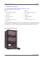
2.1 Inspecting package contens, selecting the installation location
Basic package includes the following items:
MC133
MC133f
•
Power calibrator (main unit)
•
Power calibrator (auxiliary unit)
•
Power cord
•
Power cord
•
Spare fuse
•
Spare fuse
•
Operational manual
•
Operational manual
•
Test report
•
Test report
•
Test cable 1000V/32A – 4 pcs
•
Test cable 1000V/32A – 4 pcs
•
RS232 cable
The calibrator should be powered by 230/115 V – 50/60 Hz mains. It is a laboratory instrument
whose parameters are guaranteed at 23±2 oC. Before powering on the instruments, place it on a
level surface. Do not cover the vents at the bottom side and the fan opening at the rear panel.
MC133-01 High Current Adapter
5
Operation manual
MC-133 / MC-133i Power calibrator
POWERTEK
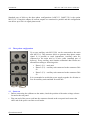
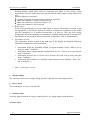
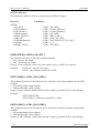
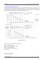
Standard part of delivery the three-phase configuration (1xMC133, 2xMC133f) is the option
MC133-01. Using this adapter all current outputs are connected in parallel and the configuration
can deliver up to 90 A in signle phase mode.
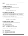
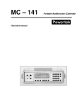
2.2
Three-phase configuration
Up to two auxiliary unit MC133f(i) can be connected to the main
unit MC133(i). This structure allows to generate three-phase output
signal. It is possible to stack instruments. Auxiliary units are
connected to the main unit by 25-wire cable (standard part of
delivery). Every auxiliary unit contains calibration data. Phases are
allocated according to following rules:
•
•
•
Phase 1 (L1) – main unit
Phase 2 (L2) – auxiliary unit connected to the connector Unit
#2
Phase 3 (L3) – auxiliary unit connected to the connector Unit
#3
It is recomended to switch the power supply together for all units or
first for auxiliary units and than for main unit.
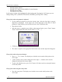
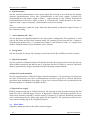
2.3 Power-on
• Before connecting the calibrator to the mains, check the position of the mains voltage selector
located at the rear panel.
•
Plug one end of the power cord into the connector located at the rear panel and connect the
other end of the power cord into a wall outlet.
Operation manual
6
MC-133 Power calibrator
POWERTEK
•
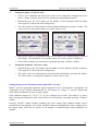
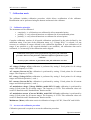
Switch on the mains switch located at the rear panel. Flat display is lit.
•
The calibrator performs internal hardware checks for 5 seconds. Configuration of the
instrument is displayed in the end of this test (connected phase channels).
N.A.
•
- unit is connected and ready
- unit is not connected
- unit is connected, but failed
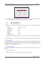
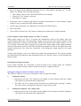
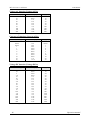
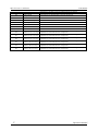
After the tests conclude, the calibrator resets to its reference state, i.e. the following parameters
are set:
Function
AC power Pac Basic
Voltage range
10 V
Set value
10 V
Current range
1A
Set value
1A
Phase
0º
Frequency
50 Hz
Output terminals
OFF
GPIB address of the calibrator is factory-preset to 2. This value is valid until the user changes
it.
Note. The calibrator resets to its reference status in case of power switching off and reconnection.
2.4 Warm-up time
The calibrator works after it is switched on and the initial checks complete. Specified parameters
are only guaranteed after the instrument warms up for 60 minutes. During this period, the
instrument cannot be calibrated. The display shows “cannot access the calibration” message if
calibration is attempted during this period.
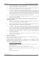
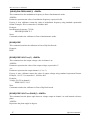
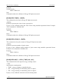
2.5 Replacement of fuse
The calibrator includes a fuse located in the mains connector at the rear panel. Replace the fuse as
follows:
•
Switch off the calibrator
•
Remove the end of power cord from the mains connector at the rear panel.
7
Operation manual
POWERTEK
MC-133 / MC-133i Power calibrator
•
Insert the blade of a flat screwdriver into the opening cut in the mains voltage selector and pull
out the fuse holder.
•
Remove the fuse and replace it with new fuse of the same rating.
Operation manual
8
MC-133 Power calibrator
POWERTEK
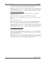
2.6 Safety precautions
The instrument has been designed in Safety Class I according to EN 61010-1. The design reflects
the requirements of A2 amendment of the standard.
Safety is ensured by the design and by the use of specific component types.
The manufacturer is not liable for the damage caused by modification of the construction or
replacement of parts with non-original ones.
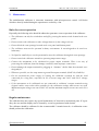
Safety symbols used on the equipment
Warning, reference to the documentation
Warning - risk of electric shock
Danger - high voltage
9
Operation manual
POWERTEK
3
3.1
MC-133 / MC-133i Power calibrator
Description of controls
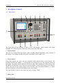
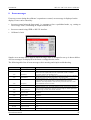
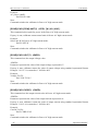
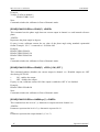
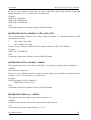
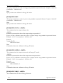
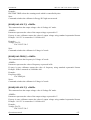
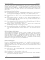
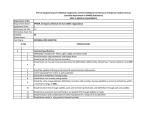
Front panel
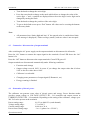
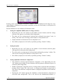
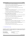
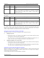
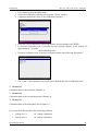
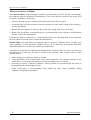
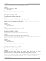
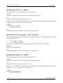
The front panel of the calibrator includes a TFT color display, control buttons and output
terminals. The following picture shows the control part of the front panel.
1
Display buttons
There are five buttons below the display, whose meaning changes depending on the contents of
the display. These buttons usually call-up the “local Menu” (units, modes, etc.).
2
Cursor buttons
Using these buttons, the cursor can be controlled within allowed limits on the display. The
keyboard includes two buttons (<, >) which allow the cursor to be set to the required position at
the display. The cursor can be moved to the left or right. These buttons are usually used to step
through the options and to move from one option to another or between the menu levels. Numeric
values can be set in some control modes as well. In these cases, the buttons marked (!, ") allow
the user to increase or decrease the number at the cursor button.
The central button is used to select value you want to change (TAB).
3
Rotary knob
Operation manual
10
MC-133 Power calibrator
POWERTEK
The rotary knob integrates several functions. By turning the knob to the left or right, the user can:
•
step through the options
•
enter numeric values
The function of the rotary knob can usually be performed by the cursor buttons. The central button
is used to confirm the selection (Select) or change the function of the rotary knob (value change or
position change).
4 Numeric keyboard
The keyboard allows the entry of numeric values on the display. ENTER button is used to confirm
the selection. CANCEL button can be used to cancel the entry.
5 Direct keyboard
MENU button is used to open the Main menu of the instrument (parameters petting). SAVE
(RECALL) buttons can be used to save (recall) the actual setting of the instrument (all values
including parameters). Capacity of the memory i sup to 100 different settings. Each setting
contains simple text description.
6 Function buttons
Function buttons can be used to call-up the functions of the calibrator directly. The following
buttons are provided:
function
key
Power
Energy
Voltage
Current
AC
DC
Output ON (Operate)
Output OFF (Standby)
P
E
U
I
AC
DC
ON
OFF
After the function mode is changed, the parameters of the respective function are restored. If the
respective function was never used, the calibrator resets to its reference values.
11
Operation manual
MC-133 / MC-133i Power calibrator
POWERTEK
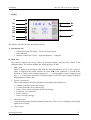
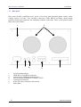
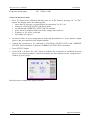
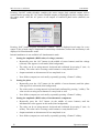
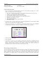
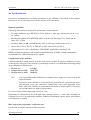
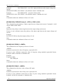
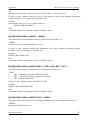
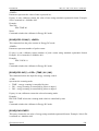
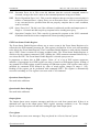
7
Display
A
B1
a
B2
B2
B2
B2
B4
B3
C
B7
B5
B6
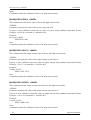
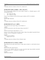
The display is divided to three horizontal sections:
A. Information line
•
•
•
Selected function (Pac Basic – Power AC basic mode)
Date and time
Remote control state (Local – keyboard, Remote – computer)
B. Main area
This section displays the set-up values of generated signals and the data related to the
calibrator status. The section includes the following types of data:
1. Main value
There is displayed main output value with the unit and indication of AC or DC (picture).
There is displayed also achal position of cursor !" if the parameter is in edit mode.
Position of cursor can be changed using keys <, > and parameter can be changed using
keys !, ", or using the rotary knob. If output voltage exceeds 50V sign of danger voltage is
displayed before main value.
2. Auxiliary parameters
This section displays auxiliary parameters of actually selected function:
•
•
•
•
•
•
Voltage (functions power and energy)
Current (functions power and energy)
Phase / Power factor (functions power and energy)
Frequency (AC functions)
Power (energy)
Dose of energy (energy)
3. Measured value
Value measured using internal multimeter with unit. Value “over” is displayed if measured
signal is out of range.
4. Outputs state
Operation manual
12
MC-133 Power calibrator
POWERTEK
Window displays which phase units are connected (one phase to three phase), which
terminals are used for signal generation and also informs about output voltage higher than
50V.
Symbols displayed in window:
- warning, displayed if output voltage is higher or equal 50V.
- phase unit (channel) is connected, output is off
- phase unit (channel) is connected, output is on
- phase unit (channel) is not connected
5. Specification
In the field specification of set-up output signal is shown. Uncertainty is related to the
main parameter. Label BUSY instead of accuracy is displayed, if calibrator is not within
specified parameters or if internal reconnection is in process. This can occur during
changing the functions, changing set parameters, switching output terminals ON and OFF.
Specification is not available in power functions “P Harmonic” and “P Interharmonic”.
6. Information section
The information section located in the right part of the display and displays additional
information related to the selected function:
•
•
•
•
information about the grounding method of output terminals: GndU, GndI as set up
using the menu “Calibrator”.
information about voltage terminal configuration (2-wire / 4-wire) as set up using the
menu “Calibrator”.
information about the use of 25-turn coil or 50-turn coil (COIL x50) as set up using the
menu “Calibrator”.
information about number of controlled output channels (only functions “Power Pac”
and “Energy Eac”).
7. Meter’s information section
C. Display softkeys
The functions of these keys change during operation (depends on actual display mode).
8 Power switch
Turns instrument AC power ON and OFF.
9 Auxiliary input
Auxiliary input terminals for energy counting and for AC output signal synchronization.
10 Meter input
13
Operation manual
POWERTEK
MC-133 / MC-133i Power calibrator
Input terminals for internal multimeter. The COM terminal is common for all measuring. The V
terminal is for DC voltage (10V) and frequency (10kHz) measuring. The mA terminal is for DC
current (20mA) measuring.
11 Current output
Current outputs HI and LO terminals.
12 Voltage output
Voltage outputs HI and LO terminals. Terminals “OUTPUT” (black background) are main output
for 2-wire connection and source for 4-wire connection. Terminals “SENSE” are for sensing in 4wire connection.
Colors on display
Common rules are used for applied color of labels and values.
1. Red color is applied, when displayed value is measured by the calibrator.
2. Blue color is applied for parameters or values, which can be set-up or modified directly
from front panel keyboard or via Main menu.
3. Black color is used for fix values, labels, notes, parameters which cannot be modified and
for other fix text with general information purpose.
4. Meaning of display buttons is always shown the lowest line. If there is no description
above display button, the button is not active in selected function.
Operation manual
14
MC-133 Power calibrator
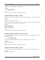
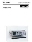
3.2
POWERTEK
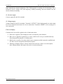
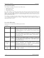
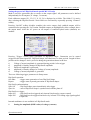
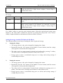
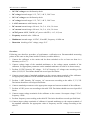
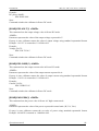
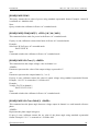
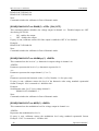
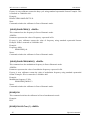
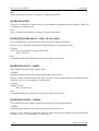
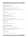
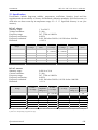
Rear panel
Rear panel includes ventilation holes, power cord socket with integrated mains switch, mains
voltage selector 115/230V, fuse, interface connectors GPIB, RS232 and RJ45, metal central
ground terminal and connectors for additional channels connection. There is also placed model
plate with serial number.
1
7
6
1
2
3
4
5
6
7
5
4
3
2
forced ventilation holes
GPIB, RS-232 and RJ45 connectors
connectors for additional channels units
fuse for internal multimeter (T100mA / 250V)
central ground terminal
power line entry with power line switch
model plate
15
Operation manual
MC-133 / MC-133i Power calibrator
POWERTEK
4
4.1
Control of the calibrator
Selection of function
After the power is switched on and the initial checks complete, the calibrator resets to its reference
state:
Function:
Voltage:
Current:
Phase:
Frequency:
Pac Basic
10V
1A
0°
50Hz
The state of the calibrator can be changed using the buttons located at the front panel in one of the
following ways:
1.
Change of function by pressing one of direct function buttons
After pressing one of the buttons P, E, U, I, DC, AC calibrator switches to the selected function
and set the last set-up parameters. Whenever function is changed, calibrator always goes over to
STANBY position. Output terminals are disconnected. All functions with direct access has
submenus, where various basic modes of the selected function can be chosen. Access to the
submenu is always vie display button Mode.
2.
Connection /disconnection of output terminals
After pressing the ON button, the output terminals of the calibrator are connected. Only those
terminals are activated which are aimed for DUT connection. To disconnect active terminals push
the OFF button.
3.
Access to the Main menu
After pressing the MENU button the calibrator displays the basic level of the setup menu. In this
menu you can change instruments setting and calibration data. Previous function is recalled after
pressing Exit softkey.
4.2
Setting the value of output signal
Edit mode
Parameters of output signal can be changed in Edit mode. Only parameters displayed in blue color
can be changed. Display can be switched to edit mode in different ways:
Operation manual
16
MC-133 Power calibrator
-
POWERTEK
Pressing numeric button
Pressing “Sel” button (in the middle of cursors buttons)
Pressing cursor button
Pressing the rotary knob
In edit mode is edited value highlighted by blue background. Pressing the “Sel” button you can
change among “blue” parameters. Edit mode is finished by pressing “Exit” softkey.
Entry of the value using numeric keyboard
•
Use the numeric keyboard to select the desired value. After the first digit is entered,
input box is displayed. In the upper row of the input box is the name of edited
parameter. Using softkeys you can enter the new value in different units.
•
Enter desired value.
•
After the entry is complete press softkey with requested unit or press “Enter” button.
“Enter” button inputs the value in basic units (V, A, W, …).
•
Calibrator sets new value.
•
The value is copied to the appropriate field in the screen and the input box disappears.
Entry of the value using cursor buttons
•
Press <, >, ! or " button. The display now includes cursor marks which points to the
active digit.
•
! and " buttons can be used to change the active digit. <, > buttons can be used to
change the position of the cursor marks
•
To get to the default screen, press “Exit” button. All values can be set using the buttons
or the rotary knob.
Entry of the value using the rotary knob
•
17
Press the rotary knob. The display now includes cursor marks which points to the
active digit.
Operation manual
MC-133 / MC-133i Power calibrator
POWERTEK
•
Turn the knob to change the active digit
•
Press the rotary knob to change to the mode which allows to change the value of the
active digit. # and $ symbols are displayed above the active digit. Active digit can be
changed by turning the knob.
•
Turn the knob to change the position of the active digit.
•
To get to the default screen press “Exit” button. All values can be set using the buttons
or the rotary knob.
•
All parameters have limits (high and low). If the entered value is outside these limits
error message is displayed (“Value too large (small)”) and new value is not accepted.
Note:
4.3
Connection / disconnection of output terminals
After switching the AC power supply on the output terminals are disconnected in all modes.
Press the “On” button to connect the output signal to the terminals. Green LED above the “On”
button is lit.
Press the “Off” button to disconnect the output terminals. Green LED goes off.
Output terminals are disconnected automatically under following conditions:
4.4
•
Function mode change
•
Output voltage exceeds 100V. It occurs if you change the output value that is below
100V to the new value above 100V.
•
Calibrator is overloaded.
•
Changing some parameters of output signal (P Harmonic, etc.)
•
Energy counting is finished.
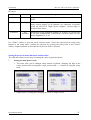
Generation of electric power
The calibrator can generate exact value of electric power and energy. Power function modes
provides output voltage at VOLTAGE OUTPUT HI – LO terminals and output current at
CURRENT OUTPUT HI – LO terminals. Depending on the setting of the calibrator, voltage up to
280 Vef can be present at the terminals.
Power setting range:
Voltage setting range:
Current setting range:
Power factor setting range:
Operation manual
0.0 VA to 8400 VA (each channel)
1 V to 280 V
0.008 A to 30 A
-1 to +1 (phase 0 to +359.99 °)
18
MC-133 Power calibrator
Frequency setting range:
POWERTEK
DC, 15 Hz to 1 kHz
Control in the power mode
•
Press “P” button on the calibrator and then select AC or DC mode by pressing “AC” or “DC”
button. The display shows the following data:
*
*
*
*
*
*
main value of set power in selected unit of measurement VA, W, VAr
voltage at VOLTAGE OUTPUT HI-LO terminals
current through CURRENT OUTPUT HI-LO terminals
power factor or the phase shift between the voltage and current in °.
frequency, if AC power is selected
uncertainty of set power
•
Set desired value of power using numeric keyboard, potentiometer or cursor buttons. Output
power is not yet connected to the output terminals.
•
Connect the instrument to be calibrated to VOLTAGE OUTPUT HI-LO and CURRENT
OUTPUT HI-LO terminals or short the CURRENT OUTPUT HI-LO terminals.
•
Press OUTPUT button.
•
Green LED is lit above the “On” button to indicate the connection of simulated electrical
power to the output terminals. Connected terminals are also displayed in the “Outputs state”
window as green circles.
Desired power is connected to output terminals.
19
Operation manual
POWERTEK
MC-133 / MC-133i Power calibrator
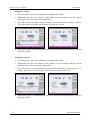
Power factor polarity (Lead/Lag softkey)
In case that phase shift between voltage and current is expressed as power factor you can change
its polarity using “Lead/Lag” softkey. The Lead polarity presents capacity load (current before
voltage). The Lag polarity presents inductance load (voltage before current).
Operation manual
20
MC-133 Power calibrator
POWERTEK
Power units (Units softkey)
The calibrator can display AC power in one of three ways:
•
•
•
apparent power in VA
active power in W
reactive power in VAr
Use “Units” softkey to open the units selection menu. Select the required expression using cursor
buttons or the rotary knob. Confirm the selection by pressing the rotary knob or the “Select”
softkey. The value of displayed power is recalculated together with new units selection. DC power
can be expressed only in W.
The calibrator can display the phase relation of output voltage and current as power factor (–1 to
+1) or as phase shift in degrees (0 to 359.99 °). Main menu is used to change the method of
displaying the phase relation.
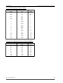
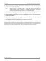
Power modes (Mode softkey)
Output power can be generated in different power modes:
AC power
Mode
Name
Description
Basic
Pac Basic
AC power basic mode. Phase shift between channels output
voltages are fixed (120º and 240º). All parameters are the same for
all channels. Number of active channels can be defined in Main
menu (1, 2 or 3).
High I
Pac High I Mode is available only if all 3 channels are connected. In this
mode current outputs of all channels are connected in parallel
(using the MC133-01 High Current Adapter). Current range is
increased three times.
Extended
Pac
Extended
Parameters for all calibrators outputs (3x voltage, 3x current) can
be set quite independently in this mode. For each output you can
define amplitude (V or A) and phase shift (º). Phase shift is relative
to the internal reference.
Harmonic
P
Harmonic
Mode is used for generation harmonic signal composed of up to 50
harmonic components. All components can be defined
independently for all outputs (3x voltage, 3x current). Beside this
mode allows modulation by sine or square signal.
P
Iharmonic
Mode is used for generation interharmonic signal. One
interharmonic component can be add independently for all outputs
(3x voltage, 3x current).
(version MC-133
only)
Interharmonic
(version MC-133
only)
21
Operation manual
MC-133 / MC-133i Power calibrator
POWERTEK
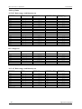
DC power
Mode
Name
Description
Basic
Pdc Basic
DC power basic mode. Only first channel 1 is controlled in this
mode.
High I
Pdc High I Mode is available only if all 3 channels are connected. In this
mode current outputs of all channels are connected in parallel
(using the MC133-01 High Current Adapter). Current range is
increased three times.
Extended
Pdc
Extended
Parameters for all calibrators outputs (3x voltage, 3x current) can
be set quite independently in this mode. For each output you can
define amplitude (V or A).
Use “Mode” softkey to open the mode selection menu. Select the required mode using cursor
buttons or the rotary knob. Confirm the selection by pressing the rotary knob or the “Select”
softkey. Output terminals are disconnected if the new mode is selected.
Setting the power in modes Pdc Basic and Pac Basic
The calibrator allows several ways of setting the value of generated power.
1.
Setting the main power value
•
The main value can be changed using numeric keyboard, changing the digit at the
cursor position after selecting the cursor position with <, > buttons or using the rotary
knob.
•
Output power is changed by changing the value of output current.
Operation manual
22
MC-133 Power calibrator
2.
POWERTEK
Setting the voltage
3.
•
The main power value can be changed by changing the voltage.
•
Repeatedly press the “Sel” button (in the middle of cursor buttons) until the voltage
value appears in edit mode (blue background).
•
The value can be set using numeric keyboard and confirmed by pressing V softkey.
The value can be set using cursor buttons or rotary knob as well.
•
Main power value is recalculated using new set voltage and existing setting of current
and power factor.
Setting the current
23
•
The main power value can be changed by changing the current.
•
Repeatedly press the “Sel” button (in the middle of cursor buttons) until the current
value appears in edit mode (blue background).
•
The value can be set using numeric keyboard and confirmed by pressing mA or A
softkey. The value can be set using cursor buttons or rotary knob as well.
•
Main power value is recalculated using new set current and existing setting of voltage
and power factor.
Operation manual
MC-133 / MC-133i Power calibrator
POWERTEK
4.
Setting the power factor (AC power only)
•
If W or Var is indicated, the main power value can be changed by changing the power
factor. Change of power factor does not change the output apparent power.
•
Repeatedly press the “Sel” button (in the middle of cursor buttons) until the power
factor (phase) value appears in edit mode (blue background).
•
The value can be set using numeric keyboard and confirmed by pressing Lead or Lag
softkey. The value can be set using cursor buttons or rotary knob as well.
•
Main power value is recalculated using new set power factor and existing setting of
current and voltage. The calculation is only made if active or reactive power is
displayed.
Setting the power in modes Pdc High I and Pac High I
Modes are available only if all 3 channels are connected (Channel 1, 2 and 3). In this mode current
outputs of all channels are connected in parallel using optional adapter. Current range is increased
three times.
Output voltage terminals are on the main unit (Channel 1).
Power setting is the same as in modes Pdc Basic a Pac Basic.
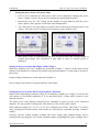
Setting the power in modes Pdc Extended and Pac Extended
Modes allow independent parameter setting for all calibrators outputs (3x voltage, 3x current) For
each output you can define amplitude (V or A) and phase shift (º). Phase shift is relative to the
internal reference.
The main power value displays summed power calculated as sum of power of all connected
channels. It is not possible to change this value directly. Color of this value is black.
Each calibrators output (U1, U2, U3, I1, I2, I3) is displayed as a folder. The folder U1 is active
after selecting the Extended mode. Next folders are activated by repeatedly pressing “Channel”
softkey.
Pressing “On/Off” softkey disables (enables) the active output. Only enabled outputs will be
connected after pressing the “On” button. Enabled outputs are highlighted by blue rectangle above
Operation manual
24
MC-133 Power calibrator
POWERTEK
the output name. After the AC power on all outputs of connected phase units (channels) are
enabled.
Picture displays state after AC power on. Both outputs of main phase unit are enabled, active is
output U1.
1.
Setting the amplitude of voltage (current)
25
•
The main power value can be changed by changing the amplitude of voltage (current).
•
Repeatedly press the “Sel” button (in the middle of cursor buttons) until the voltage
(current) value appears in edit mode (blue background).
•
The value can be set using numeric keyboard and confirmed by pressing V (mA, A)
softkey. The value can be set using cursor buttons or rotary knob as well.
•
Main power value is recalculated using new amplitude.
•
Next folders (outputs) are activated by repeatedly pressing “Channel” softkey.
Operation manual
MC-133 / MC-133i Power calibrator
POWERTEK
2.
3.
Setting the phase (AC power only)
•
If W or Var is indicated, the main power value can be changed by changing the power
factor. Change of power factor does not change the output apparent power.
•
Repeatedly press the “Sel” button (in the middle of cursor buttons) until the phase
value appears in edit mode (blue background).
•
The value can be set using numeric keyboard and confirmed by pressing ° softkey. The
value can be set using cursor buttons or rotary knob as well.
•
Main power value is recalculated using new set phase and existing setting of current
and voltage. The calculation is only made if active or reactive power is displayed.
•
Next folders (outputs) are activated by repeatedly pressing “Channel” softkey.
Setting the frequency (AC power only)
•
Repeatedly press the “Sel” button (in the middle of cursor buttons) until the frequency
value appears in edit mode (blue background).
•
The value can be set using numeric keyboard and confirmed by pressing Hz softkey.
The value can be set using cursor buttons or rotary knob as well.
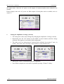
Setting the power in P Harmonic mode (model MC-133 only)
Mode is used for generation harmonic signal composed of up to 50 harmonic components. All
components can be defined independently for all outputs (3x voltage, 3x current). Beside this
mode allows modulation by sine or square signal.
Each calibrators output (U1, U2, U3, I1, I2, I3) is displayed as a folder. The folder U1 is active
after selecting the Harmonic mode. Next folders are activated by repeatedly pressing “Channel”
softkey.
Pressing “On/Off” softkey disables (enables) the active output. Only enabled outputs will be
connected after pressing the “On” button. Enabled outputs are highlighted by blue rectangle above
the output name. After the AC power on all outputs of connected phase units (channels) are
enabled.
Operation manual
26
MC-133 Power calibrator
POWERTEK
Pressing “Info” button displays informative window. There is displayed used range for every
output. Range is important for uncertainty calculation, because the uncertainty is not displayed in
mode P Harmonic.
Internal multimeter is not available in P Harmonic mode.
1.
Setting the amplitude (RMS value) of voltage (current)
2.
•
Repeatedly press the “Sel” button (in the middle of cursor buttons) until the voltage
(current) value appears in edit mode (blue background).
•
The value can be set using numeric keyboard and confirmed by pressing V (mA, A)
softkey. The value can be set using cursor buttons or rotary knob as well.
•
Output terminals are disconnected if new amplitude is set.
•
Next folders (outputs) are activated by repeatedly pressing “Channel” softkey.
Setting the phase
3.
•
Repeatedly press the “Sel” button (in the middle of cursor buttons) until the phase
value appears in edit mode (blue background).
•
The value can be set using numeric keyboard and confirmed by pressing ° softkey. The
value can be set using cursor buttons or rotary knob as well.
•
Next folders (outputs) are activated by repeatedly pressing “Channel” softkey.
Setting amplitude of harmonic components
27
•
First should be selected required harmonic component (1-50). Repeatedly press the
“Sel” button (in the middle of cursor buttons) until the parameter Harmonic appears in
edit mode (blue background).
•
Number of harmonic component can be set using numeric keyboard and confirmed by
pressing “Enter” button. The value can be set using cursor buttons or rotary knob as
well. Next to the harmonic component number is displayed amplitude of this harmonic
component.
•
Pressing the “Sel” button appears the amplitude of selected harmonic component in
edit mode (blue background). This is not valid for the fundamental harmonic (1.
Operation manual
MC-133 / MC-133i Power calibrator
POWERTEK
harmonic component). Amplitude of fundamental harmonic is calculated using the
RMS value of output signal and amplitudes of harmonic components 2-50.
4.
•
Amplitude of harmonic components 2-50 can be set using numeric keyboard and
confirmed by pressing “%” softkey. The value can be set using cursor buttons or
rotary knob as well. Amplitude can be set in range 0 to 30.000%. Amplitude is
expressed as percentage of RMS value.
•
“Harm+” (“Harm-”) softkeys facilitate listing among harmonics components. Softkeys
displays amplitude of next (previous) harmonic component.
•
All harmonic components 2-50 can be cleared by pressing “Clear” softkey. “Clear”
softkey is available if the fundamental harmonic is displayed.
•
Output terminals are disconnected if new amplitude is set.
Setting of modulation
•
After AC power on modulation is switched off (OFF). First should be selected shape of
modulation signal. Repeatedly press the “Sel” button (in the middle of cursor buttons)
until the parameter Modulation appears in edit mode (blue background). Shape can be
selected using “SIN”, “RECT” or “OFF” sofkey. Duty cycle (1 to 99%) is available for
rectangular modulation signal.
•
All harmonic components are modulated by modulation signal.
•
Frequency of modulation signal is determinated by parameter “Modulation”.
Setting the power in P Interharmonic mode (model MC-133 only)
Mode is used for generation signal composed of fundamental harmonic and one interharmonic
component. All parameters can be defined independently for all outputs (3x voltage, 3x current).
Each calibrators output (U1, U2, U3, I1, I2, I3) is displayed as a folder. The folder U1 is active
after selecting the Interharmonic mode. Next folders are activated by repeatedly pressing
“Channel” softkey.
Operation manual
28
MC-133 Power calibrator
POWERTEK
Pressing “On/Off” softkey disables (enables) the active output. Only enabled outputs will be
connected after pressing the “On” button. Enabled outputs are highlighted by blue rectangle above
the output name. After the AC power on all outputs of connected phase units (channels) are
enabled.
Pressing “Info” button displays informative window. There is displayed used range for every
output. Value of used range is important for uncertainty calculation, because the uncertainty is not
displayed in P Interharmonic mode.
Internal multimeter is not available in P Interharmonic mode.
1.
Setting the amplitude (RMS value) of voltage (current)
2.
•
Repeatedly press the “Sel” button (in the middle of cursor buttons) until the voltage
(current) value appears in edit mode (blue background).
•
The value can be set using numeric keyboard and confirmed by pressing V (mA, A)
softkey. The value can be set using cursor buttons or rotary knob as well.
•
Output terminals are disconnected if new amplitude is set.
•
Next folders (outputs) are activated by repeatedly pressing “Channel” softkey.
Setting the phase
3.
•
Repeatedly press the “Sel” button (in the middle of cursor buttons) until the phase
value appears in edit mode (blue background).
•
The value can be set using numeric keyboard and confirmed by pressing ° softkey. The
value can be set using cursor buttons or rotary knob as well.
•
Next folders (outputs) are activated by repeatedly pressing “Channel” softkey.
Setting the amplitude (RMS value) of interharmonic component
29
•
Repeatedly press the “Sel” button (in the middle of cursor buttons) until the
interharmonic value appears in edit mode (blue background).
•
The value can be set using numeric keyboard and confirmed by pressing V (mA, A)
softkey. The value can be set using cursor buttons or rotary knob as well.
•
Output terminals are disconnected if new amplitude is set.
•
Next folders (outputs) are activated by repeatedly pressing “Channel” softkey.
Operation manual
POWERTEK
MC-133 / MC-133i Power calibrator
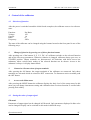
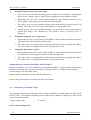
Setting the power in P Dip/Swell mode (model MC-133 only)
Mode is used for generation dips or swells on the output signal. All parameters can be defined
independently for all outputs (3x voltage, 3x current).
Each calibrators output (U1, U2, U3, I1, I2, I3) is displayed as a folder. The folder U1 is active
after selecting the Dip/Swell mode. Next folders are activated by repeatedly pressing “Channel”
softkey.
Pressing “On/Off” softkey disables (enables) the active output. Only enabled outputs will be
connected after pressing the “On” button. Enabled outputs are highlighted by blue rectangle above
the output name. After the AC power on all outputs of connected phase units (channels) are
enabled.
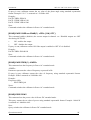
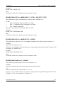
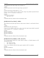
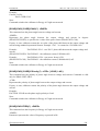
Pressing “Trigger” button starts generation of Dip/Swell shape. Generation can be started
(triggered) also from input IN3. Dip/Swell shape is divided into five time periods. Length of these
periods can be changed. Active period is during the generation shown in the box.
t1
t2
t3
t4
t5
Voltage (Current) amplitude is generated during period t1 after trigger
amplitude is fluently changed to Dip/Swell amplitude
Dip/Swell amplitude is generated
amplitude is fluently changed to Voltage (Current) amplitude
Voltage (Current) amplitude is generated
There are following trigger parameters in Setup menu:
Dip/Swell repetition:
One Shot
- trigger starts generation of one Dip/Swell shape
Repeat
- trigger starts repeated generation of Dip/Swell shapes
Dip/Swell synchronization:
Sync Off
- Dip/Swell shape starts immediately after trigger
Sync On
- start of Dip/Swell shape is synchronized with the phase 0°
Dip/Swell ext. trigger
Input Off
- Dip/Swell can be triggered only internal (keyboard or remote control)
Input IN3
- Dip/Swell can be triggered internal or by external TTL falling edge signal applied
to input IN3
Internal multimeter is not available in P Dip/Swell mode.
1.
Setting the amplitude (RMS value) of voltage (current)
Operation manual
30
MC-133 Power calibrator
2.
POWERTEK
•
Repeatedly press the “Sel” button (in the middle of cursor buttons) until the voltage
(current) value appears in edit mode (blue background).
•
The value can be set using numeric keyboard and confirmed by pressing V (mA, A)
softkey. The value can be set using cursor buttons or rotary knob as well.
•
Output terminals are disconnected if new amplitude is set.
•
Next folders (outputs) are activated by repeatedly pressing “Channel” softkey.
Setting the phase
3.
•
Repeatedly press the “Sel” button (in the middle of cursor buttons) until the phase
value appears in edit mode (blue background).
•
The value can be set using numeric keyboard and confirmed by pressing ° softkey. The
value can be set using cursor buttons or rotary knob as well.
•
Next folders (outputs) are activated by repeatedly pressing “Channel” softkey.
Setting the amplitude (RMS value) of Dip/Swell
4.
•
Repeatedly press the “Sel” button (in the middle of cursor buttons) until the Dip/Swell
value appears in edit mode (blue background).
•
The value can be set using numeric keyboard and confirmed by pressing V (mA, A)
softkey. The value can be set using cursor buttons or rotary knob as well.
•
Output terminals are disconnected if new amplitude is set.
•
Next folders (outputs) are activated by repeatedly pressing “Channel” softkey.
Setting Dip/Swell time periods
4.5
•
Repeatedly press the “Sel” button (in the middle of cursor buttons) until reuiered time
period (t1, t2, t3, t4 or t5) appears in edit mode (blue background).
•
The value can be set using numeric keyboard and confirmed by pressing ms (s)
softkey. The value can be set using cursor buttons or rotary knob as well.
•
Output terminals are disconnected if new time is set.
•
Next folders (outputs) are activated by repeatedly pressing “Channel” softkey.
Generation of electric energy
The calibrator can generate exact value of electric power and energy. Power function modes
provides output voltage at VOLTAGE OUTPUT HI – LO terminals and output current at
CURRENT OUTPUT HI – LO terminals. Depending on the setting of the calibrator, voltage up to
280 Vef can be present at the terminals.
Power setting range:
Voltage setting range:
Current setting range:
Power factor setting range:
31
0.0 VA to 8400 VA (each channel)
1 V to 280 V
0.008 A to 30 A
-1 to +1 (phase 0 to +359.99 °)
Operation manual
MC-133 / MC-133i Power calibrator
POWERTEK
Time setting range:
Frequency setting range:
1 to 10000 s
DC, 15 Hz to 1 kHz
Control in the energy mode
•
Press “E” button on the calibrator and then select AC or DC mode by pressing “AC” or “DC”
button. The display shows the following data:
*
*
*
*
*
*
*
*
main value – running energy counter in selected unit of measurement VAs, Ws, VArs
voltage at VOLTAGE OUTPUT HI-LO terminals
current through CURRENT OUTPUT HI-LO terminals
power factor or the phase shift between the voltage and current in °.
frequency, if AC power is selected
value of generated power
value of input which controls energy counting
uncertainty of energy
•
Set desired value of energy using numeric keyboard, potentiometer or cursor buttons. Output
power is not yet connected to the output terminals.
•
Connect the instrument to be calibrated to VOLTAGE OUTPUT HI-LO and CURRENT
OUTPUT HI-LO terminals or short the CURRENT OUTPUT HI-LO terminals.
•
Select the Time Control input.
•
Press ON button.
•
Green LED is lit above the “On” button to indicate the connection of simulated electrical
power to the output terminals. The calibrator starts energy dose generation. Main value
displays running energy, parameter time displays running time. Output terminals are
disconnected as soon as the time counter reaches its preset value.
Ways of energy counting (Control)
There are different ways how to control the energy dose counting. The simplest (but less accurate)
way is to count the time. The other way is to count pulses from energy meter. This method is
called “rolling start” method. Unit under test is connected to the calibrator. Press the ON key on
the calibrator. The calibrator starts to count energy after counting several pulses (rolling start).
Operation manual
32
MC-133 Power calibrator
POWERTEK
Counting is finished after the set number of pulses is reached. The calibrator disconnectes the
output terminals and shows energy delivered between set number of pulses.
Ways of energy counting:
* Time – energy is counted for set time interval
* IN1 – counting pulses on input IN1 (open collector or passive relay contact)
* IN2 – counting pulses on input IN2 (active signal in range 0 to 30V – triger level is between 2
and 4V)
Use “Control” softkey to open the energy counting method selection menu. Select the required
method using cursor buttons or the rotary knob. Confirm the selection by pressing the rotary knob
or the “Select” softkey.
Power factor polarity (Lead/Lag softkey)
In case that phase shift between voltage and current is expressed as power factor you can change
its polarity using “Lead/Lag” softkey. The Lead polarity presents capacity load (current before
voltage). The Lag polarity presents inductance load (voltage before current).
Power units (Units softkey)
The calibrator can display AC power (energy) in one of three ways:
•
•
•
apparent power in VA (VAs)
active power in W (Ws)
reactive power in Var (VArs)
Use “Units” softkey to open the units selection menu. Select the required expression using cursor
buttons or the rotary knob. Confirm the selection by pressing the rotary knob or the “Select”
softkey. The value of displayed power is recalculated together with new units selection. DC power
(energy) can be expressed only in W (Ws).
The calibrator can display the phase relation of output voltage and current as power factor (–1 to
+1) or as phase shift in degrees (0 to 359.99 °). Main menu is used to change the method of
displaying the phase relation.
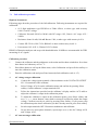
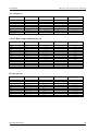
Energy modes (Mode softkey)
Output energy can be generated in different energy modes:
AC energy
Mode
Name
Description
Basic
Eac Basic
AC energy basic mode. Phase shift between channels output
voltages are fixed (120º and 240º). All parameters are the same for
all channels. Number of active channels can be defined in Main
menu (1, 2 or 3).
High I
Eac High I Mode is available only if all 3 channels are connected. In this
33
Operation manual
MC-133 / MC-133i Power calibrator
POWERTEK
mode current outputs of all channels are connected in parallel
(using the MC133-01 High Current Adapter). Current range is
increased three times.
DC energy
Mode
Name
Description
Basic
Edc Basic
DC energy basic mode. Only first channel 1 is controlled in this
mode.
High I
Edc High I Mode is available only if all 3 channels are connected. In this
mode current outputs of all channels are connected in parallel
(using the MC133-01 High Current Adapter). Current range is
increased three times.
Use “Mode” softkey to open the mode selection menu. Select the required mode using cursor
buttons or the rotary knob. Confirm the selection by pressing the rotary knob or the “Select”
softkey. Output terminals are disconnected if the new mode is selected.
Setting the energy in modes Edc Basic and Eac Basic
The calibrator allows several ways of setting the value of generated energy.
1.
2.
Setting the voltage
•
The energy (power) value can be changed by changing the voltage.
•
Repeatedly press the “Sel” button (in the middle of cursor buttons) until the voltage
value appears in edit mode (blue background).
•
The value can be set using numeric keyboard and confirmed by pressing V softkey.
The value can be set using cursor buttons or rotary knob as well.
•
Energy (power) value is recalculated using new set voltage and existing setting of
current and power factor.
Setting the current
•
The energy (power) value can be changed by changing the current.
•
Repeatedly press the “Sel” button (in the middle of cursor buttons) until the current
value appears in edit mode (blue background).
•
The value can be set using numeric keyboard and confirmed by pressing mA or A
softkey. The value can be set using cursor buttons or rotary knob as well.
•
Energy (power) value is recalculated using new set current and existing setting of
voltage and power factor.
Operation manual
34
MC-133 Power calibrator
3.
POWERTEK
Setting the power factor (AC power only)
4.
•
If Ws or VArs is indicated, the energy (power) value can be changed by changing the
power factor. Change of power factor does not change the output apparent energy.
•
Repeatedly press the “Sel” button (in the middle of cursor buttons) until the power
factor (phase) value appears in edit mode (blue background).
•
The value can be set using numeric keyboard and confirmed by pressing Lead or Lag
softkey. The value can be set using cursor buttons or rotary knob as well.
•
Energy (power) value is recalculated using new set power factor and existing setting of
current and voltage. The calculation is only made if active or reactive power is
displayed.
Setting the frequency (AC energy only)
5.
•
Repeatedly press the “Sel” button (in the middle of cursor buttons) until the frequency
value appears in edit mode (blue background).
•
The value can be set using numeric keyboard and confirmed by pressing Hz softkey.
The value can be set using cursor buttons or rotary knob as well.
Setting the time (pulse counter)
•
Repeatedly press the “Sel” button (in the middle of cursor buttons) until the time value
(or inputs IN1 or IN2) appears in edit mode (blue background).
•
The value can be set using numeric keyboard and confirmed by pressing Hz softkey.
The value can be set using cursor buttons or rotary knob as well.
Setting the power in modes Edc High I and Eac High I
Modes are available only if all 3 channels are connected (Channel 1, 2 and 3). In this mode current
outputs of all channels are connected in parallel (using the MC133-01 High Current Adapter).
Current range is increased three times.
Output voltage terminals are on the main unit (Channel 1).
Power setting is the same as in modes Edc Basic a Eac Basic.
4.6
Generation of calibrated voltage
The calibrator can generate calibrated voltage. Output terminals for voltage ranges are VOLTAGE
OUTPUT HI – LO terminals. Depending on the setting of the calibrator, voltage up to 280 Vef can
be present at the terminals.
Voltage setting range:
1 V to 280 V
Control in the voltage mode
35
Operation manual
MC-133 / MC-133i Power calibrator
POWERTEK
•
Press “U” button on the calibrator and then select AC or DC mode by pressing “AC” or “DC”
button. The display shows the following data:
*
*
*
main voltage value at VOLTAGE OUTPUT HI-LO terminals
frequency, if AC voltage is selected
uncertainty of voltage
•
Set desired value of voltage using numeric keyboard, potentiometer or cursor buttons. Output
voltage is not yet connected to the output terminals.
•
Connect the instrument to be calibrated to VOLTAGE OUTPUT HI-LO.
•
Press ON button.
•
Green LED is lit above the “On” button to indicate the connection of output terminals.
Control sequence when output voltage over 100 V is selected
When output voltage over 100 V is selected, the information section of the display shows the
symbol which informs that a life-threatening voltage will be present at the output terminals. If the
output terminals are currently connected, they will be disconnected when output voltage over 100
V is selected. ON button must be pressed to reconnect the output signal to the output terminals.
After the ON button is pressed, ON LED is lit and the information section of the display shows the
symbol notifying the user about the connection of the dangerous output signal to the output
terminals.
Voltage, and frequency can be set without the outputs being disconnected. The output terminals
are automatically disconnected when changing between AC and DC ranges or when changing the
function mode.
Overloading of output terminals
If the output terminals are overloaded or short-circuited in the voltage mode, the calibrator
disconnects the signal from the output terminals and reports “Output Overload”.
Setting the voltage in modes Udc Basic and Uac Basic
The calibrator allows several ways of setting the value of generated voltage.
1.
2.
Setting the voltage
•
Repeatedly press the “Sel” button (in the middle of cursor buttons) until the voltage
value appears in edit mode (blue background).
•
The value can be set using numeric keyboard and confirmed by pressing V softkey.
The value can be set using cursor buttons or rotary knob as well.
Setting the frequency (AC voltage only)
•
Repeatedly press the “Sel” button (in the middle of cursor buttons) until the frequency
value appears in edit mode (blue background).
Operation manual
36
MC-133 Power calibrator
•
4.7
POWERTEK
The value can be set using numeric keyboard and confirmed by pressing Hz softkey.
The value can be set using cursor buttons or rotary knob as well.
Generation of calibrated current
The calibrator can generate calibrated current. Output terminals for current ranges are CURRENT
OUTPUT HI – LO terminals.
Current setting range:
30 mA to 30 A
When 25/50-turn coil (option 140-50) is used, AC current range is to 1500 A.
Control in the current mode
•
Press “I” button on the calibrator and then select AC or DC mode by pressing “AC” or “DC”
button. The display shows the following data:
*
*
*
main current trought the CURRENT OUTPUT HI-LO terminals
frequency, if AC current is selected
uncertainty of current
•
Set desired value of current using numeric keyboard, rotary knob or cursor buttons. Output
current is not yet connected to the output terminals.
•
Connect the instrument to be calibrated to CURRENT OUTPUT HI-LO.
•
Press ON button.
•
Green LED is lit above the “On” button to indicate the connection of output terminals.
•
If Coil x50 or Coil x25 function is activated (see below – Main menu), the optional current
coil must be connected to the output terminals. The calibrator can be used to calibrate clamp
Ammeters up to 1500 A.
Overloading the terminals
When external circuit connected to current output terminals is disconnected or there is higher
voltage at the load than permitted, the calibrator disconnects the output terminals and displays
“Output Overload” message. The same message can be displayed when 50-turn coil is used for
AC current output at frequencies above 80 Hz. It depends on the set current and the type of
ammeter connected.
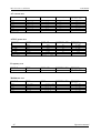
Current modes (Mode softkey)
Output current can be generated in different current modes:
AC current
37
Operation manual
MC-133 / MC-133i Power calibrator
POWERTEK
Mode
Name
Description
Basic
Iac Basic
AC current basic mode. Only first channel 1 is controlled in this
mode.
High I
Iac High I
Mode is available only if all 3 channels are connected. In this
mode current outputs of all channels are connected in parallel
(using the MC133-01 High Current Adapter). Current range is
increased three times.
Mode
Name
Description
Basic
Idc Basic
DC current basic mode. Only first channel 1 is controlled in this
mode.
High I
Idc High I
Mode is available only if all 3 channels are connected. In this
mode current outputs of all channels are connected in parallel
(using the MC133-01 High Current Adapter). Current range is
increased three times.
DC current
Use “Mode” softkey to open the mode selection menu. Select the required mode using cursor
buttons or the rotary knob. Confirm the selection by pressing the rotary knob or the “Select”
softkey. Output terminals are disconnected if the new mode is selected.
Setting the current in modes Idc Basic and Iac Basic
The calibrator allows several ways of setting the value of generated current.
1.
2.
Setting the current
•
Repeatedly press the “Sel” button (in the middle of cursor buttons) until the current
value appears in edit mode (blue background).
•
The value can be set using numeric keyboard and confirmed by pressing mA or A
softkey. The value can be set using cursor buttons or rotary knob as well.
Setting the frequency (AC current only)
•
Repeatedly press the “Sel” button (in the middle of cursor buttons) until the frequency
value appears in edit mode (blue background).
•
The value can be set using numeric keyboard and confirmed by pressing Hz softkey.
The value can be set using cursor buttons or rotary knob as well.
Setting the current in modes Idc High I and Iac High I
Modes are available only if all 3 channels are connected (Channel 1, 2 and 3). In this mode current
outputs of all channels are connected in parallel (using the MC133-01 High Current Adapter).
Current range is increased three times.
Current setting is the same as in modes Idc Basic a Iac Basic.
Operation manual
38
MC-133 Power calibrator
5
POWERTEK
Multimeter
The calibrator includes a built-in multimeter which can measure DC voltage, DC current and
frequency. Measured signal should be connected to the “METER INPUT” terminals. Terminals
mA, COM are for current measurements. Terminals V, COM are for voltage and frequency
measurements.
The manufacturer does not recommend connection of multimeter inputs to
calibrator outputs.
Such connection can result in presence of high voltage at multimeter inputs,
which can damage the multimeter.
5.1
Function selection
•
Measurement function should be selected in Main menu (item Meter).
•
Press UP, DOWN display buttons or use the rotary knob to select one of the following
functions:
*
*
*
Voltage – DC voltage range 10V
Current – DC current range 20mA
Frequency – frequency range 10 kHz
Notes:
*
The multimeter can be used as a DC multimeter with ranges 10V and 20mA.
*
Frequency measurement is possible up to 15 kHz. Input signal must be within 0.2 to 5 V
range. Square wave or pulse shape of the input signal is expected.
39
Operation manual
MC-133 / MC-133i Power calibrator
POWERTEK
6
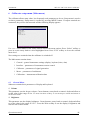
Calibrator setup menu (Main menu)
The calibrator allows many other, less frequently used parameters to be set. Setup menu is used to
set these parameters. Setup menu is opened by pressing MENU button. If output terminals are
connected, they will be disconnected and the following display appears:
Use ! or " cursor button or the rotary knob to browse the menu options. Press “Select” softkey or
press in on the rotary knob to select highlighted item. Press “Exit” softkey to leave the selected
menu level.
New settings are retained when the calibrator is switched off.
The Main menu contains items:
*
General – general instruments settings (display, keyboard, time, date)
*
Interface – parameters of instruments remote control
*
Calibrator – parameters of signal generation
*
Meter – parameters of multimeter
*
Calibration – instruments calibration data
6.1 General Menu
Submenu contains basic parameters of display and keyboard.
1. Volume
This parameter sets the beeper volume. Cursor buttons, rotary knob or numeric keyboard allow to
set the value in the range of 0 to 15. Press the Write softkey to set the beeper volume and return to
the General menu.
2. Brightness
This parameter sets the display brightness. Cursor buttons, rotary knob or numeric keyboard allow
to set the value in the range of 0 to 7. Press the Write softkey to set the display’s brightness and
return to the General menu.
Operation manual
40
MC-133 Power calibrator
POWERTEK
3. Beeper
This parameter enables / disables the signalization of pressed key. Possible states are “Beep On”
and “Beep Off”. Press the Select softkey or press in on the rotary knob to set the selected state.
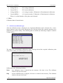
4. Calibration Password
This parameter sets the calibration password. Calibration password is a five-digit number, which
must be entered to access the calibration mode. If the calibration password is set to 0, this
information is displayed in the General menu. Other values are displayed as “Secret”.
You will be prompted to enter the present calibration password (use the numeric keybord and p%es
Enter). Now you can change the calibration password. Cursor buttons, rotary knob or numeric
keyboard allow to set the value in the range of 0 to 99999. Press the Write softkey to set the
display’s brightness and return to the General menu.
Note: It is advisable to write down actual calibration code if changed. If you forget the
calibration code, you have to send the calibrator to the manufacturer.
5. Time
Setting the real time. The parameter can be changed using cursor buttons, rotary knob or numeric
keyboard.
6. Date
Setting the date. The parameter can be changed using cursor buttons, rotary knob or numeric
keyboard.
7. Device Information
Viewing the device information. Displays the serial number and software version.
6.2 Interface Menu
Submenu contains remote control parameters.
1. Active interface
Sets the type of interface used to calibrator’s remote control. By selecting an item from the list
IEEE488, RS232 or Ethernet type can be selected. The calibrator can be remotely controlled only
using the selected interface.
2. IEEE488 address
Sets the calibrator’s IEEE488 (GPIB) address. Cursor buttons, rotary knob or numeric keyboard
allow to set the value in the range of 0 to 30. Press the Write softkey to set the address and return to
the Interface menu. Address 02 is set by the manufacturer.
3. Baud rate
Sets the communication speed of RS232 bus. By selecting an item from the list 1200, 2400, 4800,
9600, 19200, 38400, 76800 or 115200 Bd can be selected.
4. Ethernet settings
Unique fix IP address.
41
Operation manual
MC-133 / MC-133i Power calibrator
POWERTEK
*
IP address
*
Local network mask
*
Local network gateway
6.3 Calibrator Menu
Submenu contains parameters that affect generated signal.
1. Voltage sources GND
This parameter allows to connect Lo terminals of all voltage channels to GND. In practice this
means that Lo voltage terminals are grounded. By selecting an item from the list GndU Off and
GndU On type can be selected.
2. Current sources GND
This parameter allows to connect Lo terminals of all current channels to GND. In practice this
means that Lo current terminals are grounded. By selecting an item from the list GndI Off and
GndI On type can be selected.
It is recommended to ground all output channels (GndU On, GndI On). If the meter to be
calibrated has Lo terminal grounded, it is recommended to unground the corresponding
calibrator’s output to exclude ground loops.
Note
If neither the calibrator’s output, nor the meter’s inputs are grounded, signal/noise ratio can arise
at the calibrator’s output.
3. Remote sense
Sets the output voltage terminals configuration. By selecting an item from the list Sense 2W (2terminals connection) and Sense 4W (4-terminals connection) sense can be selected. Setting is
valid for all channels.
4. Phase unit
Sets the unit used for presentation the phase shift between the voltage and current output in the
power and energy generation modes. By selecting an item from the list Deg (º) and Cos (Lead,
Lag) unit can be selected.
5. Current coil
Sets the calibrator for connection the 25/50-turn current coil (clamp ammeters calibration). The
coil multiplies the output current either 25 times or 50 times depending on set parameter. By
selecting an item from the list Coil Off, Coil x25 and Coil x50 type of connected current coil can
be selected.
Operation manual
42
MC-133 Power calibrator
POWERTEK
6. Synchronization
Sets the external synchronization of the output signal. By selecting an item from the list Internal
(internal synchronization), Power line (synchronization to the power supply), External IN1
(synchronization to the passive signal on input 1 – output colector or relay contact), External IN2
(synchronization to the active signal on input 2) a External IN3 (synchronization to the active
signal on input 3) type of frequency synchronization coil can be selected.
Note:
External synchronized signal has larger distortion than internal synchronized signal because of
fine frequency tuning.
7. Active channels (Pac, Eac)
Sets the number of controlled channels in the three phase configuration. This parameter is valid
only for Pac Basic and Eac Basic function modes. By selecting an item from the list 1 (output is
from the main channel only), 1-2 (output from Channel 1 and Channel 2) and 1-2-3 (output from
all three channels) number of used channels can be selected.
8. Energy units
Sets the unit used for energy. By selecting an item from the list Ws and Wh unit can be selected.
9. Dip-Swell repetition
Sets the repetition of Dip/Swell shape in P Dip/Swell mode. By selecting an item from the list One
Shot (without repetition) and Repeat can be repetition selected. If Repeat is selected, Dip/Swell
shape is generated after trigger repeatedly until disconnecting output terminals.
10. Dip-Swell synchronization
Sets the synchronization of Dip/Swell shape with internal phase 0°. By selecting an item from the
list Sync Off and Sync On can be synchronization selected. If Sync Off is selected, Dip/Swell
generation starts immediately after trigger. If Sync On is selected, Dip/Swell is synchronized with
the internal phase 0° (channels with phase shift 0°).
11. Dip-Swell ext. trigger
Enables external triggering in P Dip/Swell mode. By selecting an item from the list Input Off and
Input IN3 can be external trigger selected. If Input Off is selected, Dip/Swell generation can be
started only internal (keyboard or remote control). If Input IN3 is selected, Dip/Swell generation
can be started internal or by falling edge applied to the input IN3. The input must remain low for
10&s after the falling edge to be recognized properly.
6.4 Meter Menu
Submenu contains parameters that affect measured signal.
43
Operation manual
POWERTEK
MC-133 / MC-133i Power calibrator
1. Function
Sets the internal multimeter measuring function and range. By selecting an item from the list
Voltage (DC voltage 0-12V), Current (DC current 0-24mA) and Frequency (Frequency 1Hz15kHz) function can be selected.
6.5 Calibration Menu
Calibration password is required to access the Calibration Menu. Default calibration password is
“0”. For more detail about calibration see the chapter 7.
Operation manual
44
MC-133 Power calibrator
7
POWERTEK
Calibration mode
The calibrator includes calibration procedure, which allows recalibration of the calibrator.
Recalibration can be performed using the buttons and menu in the calibrator.
7.1 Calibration principles
The instrument can be calibrated:
•
•
•
completely, i.e. all functions are calibrated in all recommended points
partially, i.e. only selected functions are calibrated in all recommended points
partially, i.e. only selected functions are calibrated in selected points
Complete calibration consists of all partial calibrations performed in the order defined by the
calibration menu. If an item of the calibration menu, e.g. “Voltage DC#1” is selected, it is not
necessary to calibrate all ranges defined by the calibration algorithm. If new calibration of all
ranges is not possible (e.g. the required standard is not available), old calibration data can be
confirmed, i.e. current step of the calibration can be skipped.
Calibration interruption can be performed in any point of the calibration
procedure. However this particular calibration influences parameters of the
calibrator.
Accuracy of the calibrator is guaranteed when full calibration was done.
AC voltage (Voltage AC#x) calibration is performed by setting 2 fixed points for all voltage
ranges. The frequency is 55 Hz.
AC current (Current AC#x) calibration is performed by setting 2 fixed points for all current
ranges. The frequency is 55 Hz.
DC voltage (Voltage DC#x) calibration is performed by setting 2 fixed points for all voltage
ranges and for both polarities (+ and -).
DC current (Current DC#x) calibration is performed by setting 2 fixed points for all current
ranges and for both polarities (+ and -).
AC modulation voltage (Voltage MOD#x, model MC-133 only) calibration is performed by
setting 2 fixed points for all voltage ranges. The frequency is 55 Hz. This calibration values are
used in P Harmonic and P Interharmonic function modes.
AC modulation current (Current MOD#x, model MC-133 only) calibration is performed by
setting 2 fixed points for all current ranges. The frequency is 55 Hz. This calibration values are
used in P Harmonic and P Interharmonic function modes.
Multimeter (Meter) calibration consist in calibration of ranges 10V DC, 20mA DC and 10 kHz.
7.2 Access to the calibration procedure
Calibration password is required to access the calibration procedure.
45
Operation manual
MC-133 / MC-133i Power calibrator
POWERTEK
•
•
•
Press Menu to open the Main menu.
Select the Calibration submenu and press the “Select” softkey.
Calibrator requests the entry of the calibration password.
•
•
•
Enter the correct calibration code using numeric keyboard and press ENTER.
If incorrect calibration code is entered, an error message appears on the display for
approximately 3 seconds:
Bad calibration code!
If correct calibration code is entered, calibration menu with following list appears.
•
Use ! and " cursor buttons to move the cursor through the list of calibration items.
1. Channel #1
Calibration data of the main unit (Channel 1).
2. Channel #2
Calibration data of the second phase unit (Channel 2).
3. Channel #3
Calibration data of the third phase unit (Channel 3).
Every item from the list above has following submenu:
•
Voltage AC# x
- AC voltage calibration
•
Current AC# x
- AC current calibration
Operation manual
46
MC-133 Power calibrator
POWERTEK
•
Voltage DC# x
- DC voltage calibration
•
Current DC# x
- DC current calibration
•
Voltage MOD# x
- AC voltage in modes P Harmonic a P Interharmonic calibration
•
Current MOD# x
- AC current in modes P Harmonic a P Interharmonic calibration
Where x is ordinal number of the phase unit (channel).
4. Meter
Calibration data of internal meter.
7.3 Selection of calibration type
After the calibration menu is displayed, one of partial calibrations can be selected. Use ! and "
cursor buttons to move the cursor through the list. Having selected the required function to be
calibrated, press Select softkey. The following data are shown (the following example is valid for
Voltage AC#1):
The table lists recommended calibration points. Having selected the required calibration point
using Select softkey, the following data are shown.
Softkeys have the following meaning:
Write
new calibration value is entered into the memory, old value is lost. The calibrator
returns to the previous menu.
Skip
current calibration step is skipped, old value is retained in the memory. The calibrator
returns to the previous menu.
47
Operation manual
MC-133 / MC-133i Power calibrator
POWERTEK
Moreover, the display shows the range which is being calibrated (Range 10Vac), and the value to
be set at the external standard multimeter (value in brackets 1V).
Setting the new calibration data
Use cursor buttons, rotary knob or numeric keyboard to set such main data on the display, when
the output signal measured by external standard multimeter reaches the required calibration point.
When the standard output value is reached, press Write softkey to write new calibration value to
the calibration memory. If you press Exit softkey, the calibrator ignores the new value and old
value is retained.
The procedure is repeated for all calibration points of the selected function. If you press Exit
softkey the calibrator returns back to the previous menu level.
Termination of calibration
Calibration can be terminated by repeated press the Exit softkey until the calibrator returns to the
Main menu.
Calibration points
Each function of the calibrator has assigned fixed calibration points which have to be set during
the calibration.
The calibrator needs no calibration of the following parameters:
•
frequency
•
phase relationship (power factor) of output voltage and current in AC power and AC
energy generation modes
•
DC and AC power and energy
Operation manual
48
MC-133 Power calibrator
POWERTEK
Voltage AC function (Voltage AC#x)
Nominal value [V]
1
10
10
30
30
70
70
140
140
280
Table AC voltage
Set limits [V]
Range [V]
100 u
500 u
1m
2m
4m
4m
7m
7m
15 m
15 m
10
10
30
30
70
70
140
140
280
280
Current AC function (Current AC#x)
Nominal value[A]
30 m
300 m
300 m
1
1
2
2
5
5
10
10
30
Table AC current
Set limits [A]
Range [A]
10 u
15 u
30 u
50 u
100 u
100 u
200 u
250 u
500 u
500 u
1m
1.5 m
300 m
300 m
1
1
2
2
5
5
10
10
30
30
Voltage DC function (Voltage DC#x)
Nominal value [V]
1
10
-1
-10
10
30
-10
-30
30
70
-30
-70
70
140
-70
-140
140
280
-140
-280
Table DC voltage
49
Set limits [V]
Range [V]
100 u
500 u
100 u
500 u
1m
2m
1m
2m
4m
4m
4m
4m
7m
7m
7m
7m
15 m
15 m
15 m
15 m
10
10
-10
-10
30
30
-30
-30
70
70
-70
-70
140
140
-140
-140
280
280
-280
-280
Operation manual
MC-133 / MC-133i Power calibrator
POWERTEK
Current DC function (Current DC#x)
Nominal value [A]
30 m
300 m
-30 m
-300 m
300 m
1
-300 m
-1
1
2
-1
-2
2
5
-2
-5
5
10
-5
-10
10
30
-10
-30
Table DC current
Set limits [A]
Range [A]
10 u
15 u
10 u
15 u
30 u
50 u
30 u
50 u
100 u
100 u
100 u
100 u
200 u
250 u
200 u
250 u
500 u
500 u
500 u
500 u
1m
1.5 m
1m
1.5 m
300 m
300 m
-300 m
-300 m
1
1
-1
-1
2
2
-2
-2
5
5
-5
-5
10
10
-10
-10
30
30
-30
-30
Voltage AC modulation function (Voltage MOD#x)
Nominal value [V]
Set limits [V]
Range [V]
1
10
10
30
30
70
70
140
140
280
Table MOD AC voltage
100 u
500 u
1m
2m
4m
4m
7m
7m
15 m
15 m
10
10
30
30
70
70
140
140
280
280
Operation manual
50
MC-133 Power calibrator
POWERTEK
Current AC modulation function (Current MOD#x)
Nominal value[A]
Set limits[A]
Range [A]
30 m
300 m
300 m
1
1
2
2
5
5
10
10
30
Table MOD AC current
10 u
15 u
30 u
50 u
100 u
100 u
200 u
250 u
500 u
500 u
1m
1.5 m
300 m
300 m
1
1
2
2
5
5
10
10
30
30
Set limits [-]
Range [-]
50 u
200 u
50 nA
500 nA
200 mHz
10 V
10 V
20 mA
20 mA
10 kHz
Multimetr (Meter)
Nominal value [-]
0V
10 V
0 mA
20 mA
10 kHz
Table Multimeter
51
Operation manual
MC-133 / MC-133i Power calibrator
POWERTEK
7.4
Full calibration procedure
Required instruments
Following pages describe procedure of the full calibration. Following instruments are required for
calibration:
•
81/2 digit multimeter type HP3458A or Fluke 8508A, or other type with accuracy
0.001 % on DC voltage
•
Calibrator Powertek M142 or M140 with DC ranges 10V, 20mA a AC range 10V /
10kHz.
•
Resistance shunt 10 m#, 100 m# Burster 1280, or other type with accuracy 0.01%
•
Counter HP 53181A, HO 53130, BM 642 or other with accuracy 0,001 %
•
Powermeter 0.02- 0.05 %, Zimmer LG95 or better
HP8903A Distortion analyzer and scope with bandwidth min. 20 MHz are recommended for THD
measuring of AC signals.
Calibration procedure
1.
Connect the calibrator and the multimeter to the mains and let them switched on for at least
three hours in a laboratory at 23±1 oC.
2.
Press Menu button to call up the Main menu, select Calibration end press Select softkey to
enter the calibration menu.
3.
Enter the calibration code and press Enter button (default calibration code is “0”).
4.
AC voltage ranges calibration
5.
a)
Connect the voltage input terminals of the multimeter to the VOLTAGE OUTPUT
HI - LO terminals of the calibrator.
b)
Select Voltage AC#1 from the calibration menu and confirm by pressing Select
softkey. Switch calibrator’s output terminals ON.
c)
Follow the instructions provided on the calibrator’s display and the ACU table to
adjust the calibrator’s output in the calibration points.
d)
To adjust the calibrator’s output in the calibration points, press Select softkey and
use <, >, ", ! cursor buttons, rotary knob or numeric keyboard to adjust the output
voltage. Confirm correctly set value by pressing Write softkey. If you want to skip
the calibration point whose calibration you have already entered, press Exit softkey.
e)
Switch output terminals OFF. Disconnect multimeter and calibrator.
f)
In case there are more phase channels, repeat steps a) to e) also for Voltage AC#2
and Voltage AC#3.
AC current ranges calibration
Operation manual
52
MC-133 Power calibrator
6.
POWERTEK
a)
Select Current AC#1 from the calibration menu and confirm by pressing Select
softkey. Set the same function on external multimeter.
b)
Follow the instructions provided on the calibrator’s display and the ACI table to
adjust the calibrator’s output in the calibration points.
c)
To adjust the calibrator’s output in the calibration points, press Select softkey and
use <, >, ", ! cursor buttons, rotary knob or numeric keyboard to adjust the output
voltage. Confirm correctly set value by pressing Write softkey. If you want to skip
the calibration point whose calibration you have already entered, press Exit softkey.
d)
Resistance shunt should be used on 2, 5, 10 and 30 A ranges, if standard multimeter
does not cover this range.
e)
In case there are more phase channels, repeat steps a) to d) also for Current AC#2
and Current AC#3.
DC voltage ranges calibration
7.
a)
Select Voltage DC#1 from the calibration menu and confirm by pressing Select
softkey. Switch calibrator’s output terminals ON.
b)
Follow the instructions provided on the calibrator’s display and the DCU table to
adjust the calibrator’s output in the calibration points.
c)
To adjust the calibrator’s output in the calibration points, press Select softkey and
use <, >, ", ! cursor buttons, rotary knob or numeric keyboard to adjust the output
voltage. Confirm correctly set value by pressing Write softkey. If you want to skip
the calibration point whose calibration you have already entered, press Exit softkey.
d)
Switch output terminals OFF. Disconnect multimeter and calibrator.
e)
In case there are more phase channels, repeat steps a) to d) also for Voltage DC#2
and Voltage DC#3.
DC current ranges calibration
8.
a)
Select Current DC#1 from the calibration menu and confirm by pressing Select
softkey. Set the same function on external multimeter.
b)
Follow the instructions provided on the calibrator’s display and the DCI table to
adjust the calibrator’s output in the calibration points.
c)
To adjust the calibrator’s output in the calibration points, press Select softkey and
use <, >, ", ! cursor buttons, rotary knob or numeric keyboard to adjust the output
voltage. Confirm correctly set value by pressing Write softkey. If you want to skip
the calibration point whose calibration you have already entered, press Exit softkey.
d)
Resistance shunt should be used on 2, 5, 10 and 30 A ranges, if standard multimeter
does not cover this range.
e)
In case there are more phase channels, repeat steps a) to d) also for Current DC#2
and Current DC#3.
AC voltage modulation ranges calibration (P Harmonic, P Interharmonic modes,
model MC-133 only)
53
Operation manual
MC-133 / MC-133i Power calibrator
POWERTEK
9.
10.
a)
Select Voltage MOD#1 from the calibration menu and confirm by pressing Select
softkey. Switch calibrator’s output terminals ON.
b)
Follow the instructions provided on the calibrator’s display and the MOD ACU
table to adjust the calibrator’s output in the calibration points.
c)
To adjust the calibrator’s output in the calibration points, press Select softkey and
use <, >, ", ! cursor buttons, rotary knob or numeric keyboard to adjust the output
voltage. Confirm correctly set value by pressing Write softkey. If you want to skip
the calibration point whose calibration you have already entered, press Exit softkey.
d)
Switch output terminals OFF. Disconnect multimeter and calibrator.
e)
In case there are more phase channels, repeat steps a) to d) also for Voltage
MOD#2 and Voltage MOD#3.
AC current modulation ranges calibration (P Harmonic, P Interharmonic modes,
model MC-133 only)
a)
Select Current MOD#1 from the calibration menu and confirm by pressing Select
softkey. Set the same function on external multimeter.
b)
Follow the instructions provided on the calibrator’s display and the MOD ACI
table to adjust the calibrator’s output in the calibration points.
c)
To adjust the calibrator’s output in the calibration points, press Select softkey and
use <, >, ", ! cursor buttons, rotary knob or numeric keyboard to adjust the output
voltage. Confirm correctly set value by pressing Write softkey. If you want to skip
the calibration point whose calibration you have already entered, press Exit softkey.
d)
Resistance shunt should be used on 2, 5, 10 and 30 A ranges, if standard multimeter
does not cover this range.
e)
In case there are more phase channels, repeat steps a) to d) also for Current
MOD#2 and Current MOD#3.
Multimeter calibration
Built-in multimeter calibration consists of the calibration of 10 V voltage range, 20 mA
current range and 10 kHz frequency range.
External calibrator of higher precision class should be used to calibrate the built-in
multimeter (Powertek M142). If accurate external calibrator is not available an 81/2 digit
multimeter is recommended for calibration.
a)
10 V DC voltage range calibration
•
Select Meter from the calibration menu. Press Select softkey to select the first
calibration point, 0 V.
•
Make short on calibrators input terminals METER INPUT V-COM.
•
Main value presents the calibration point. Leave value 0.000 and press Write
softkey.
•
Select calibration point 10 V.
Operation manual
54
MC-133 Power calibrator
•
Connect external voltage 10 V to the calibrator input terminals METER INPUT VCOM. Exact value can be measured by paralel standard voltmeter.
•
Adjust main value on the display. It should be equal to the value measured by
standard multimeter. Use <, >, ", ! cursor buttons, rotary knob or numeric
keyboard to adjust the main value. Confirm new value by pressing Write softkey.
b)
20 mA DC current range calibration
•
Select Meter from the calibration menu. Press Select softkey to select the first
calibration point, 0 mA.
•
Make short on calibrators input terminals METER INPUT mA-COM.
•
Main value presents the calibration point. Leave value 0.000 and press Write
softkey.
•
Select calibration point 20 mA.
•
Connect external current source 20 mA to the calibrator input terminals METER
INPUT mA-COM. Exact value can be measured by serial standard ampmeter.
•
Adjust main value on the display. It should be equal to the value measured by
standard multimeter. Use <, >, ", ! cursor buttons, rotary knob or numeric
keyboard to adjust the main value. Confirm new value by pressing Write softkey.
c)
55
POWERTEK
10 kHz frequency range calibration
•
Select calibration point 10 kHz.
•
Connect external AC voltage 10 kHz (voltage between 5 to 10 V) to the calibrator
input terminals METER INPUT V-COM. Exact frequency value can be measured
by paralel standard counter.
•
Adjust main value on the display. It should be equal to the value measured by
standard counter. Use <, >, ", ! cursor buttons, rotary knob or numeric keyboard to
adjust the main value. Confirm new value by pressing Write softkey.
Operation manual
MC-133 / MC-133i Power calibrator
POWERTEK
8
Error messages
If an error occurs during the calibrator’s operation or control, error message is displayed on the
display. Errors can be caused by:
•
Incorrect control using the front panel, i.e. attempts to force a prohibited mode, e.g. setting an
out-of-range value, overloading of output terminals etc.,
•
Incorrect control using GPIB or RS-232 interface.
•
Calibrator’s fault.
Sample error message which appears when too large value is attempted to set up is shown bellow.
All error messages are displayed in the frame overlapped main screen.
The following table lists all error messages, their meaning and simple troubleshooting.
ID
Error message
Description
Remote interface error. A command was received which generates too much
data to fit in the output buffer and the output buffer is full. Command
execution continues but all data are lost.
Remote interface error. The calibrator was addressed to talk but a command
has not been received which sends data to the output buffer.
Remote interface error. A command was received which sends data to the
output buffer, but the output buffer contained data from a previous
command. The output buffer is cleared when power has been off, or after
reset command has been executed.
-430
Deadlocked.
-420
Unterminated.
-410
Interrupted.
-363
Input buffer overrun
-220
Invalid parameter
-140
Character data
-120
Numeric data
Remote interface error.
Remote interface error. An invalid character string was received. Check to
see if you have enclosed the character string in single or double quotes and
that the string contains valid ASCII character.
Remote interface error. Received command doesn’t contain valid character
parameter.
Remote interface error. Received command doesn’t contain valid numeric
parameter.
-110
Command header
Remote interface error. Received command isn’t valid.
501
Eeprom write.
Eeprom write failed.
502
Eeprom read.
Eeprom read failed.
503
Eeprom error.
701,704
Output overload
Eeprom data lost. Check calibration data.
Output signal over specified limits. Decrease signal level or decrease the
load.
703
High temperature
Calibrator power stage overheated. Disconnect external load. Ambient
Operation manual
56
MC-133 Power calibrator
POWERTEK
temperature is too high or forced ventilation holes are blocked.
705
Input overload
Input signal over specified limits. Decrease signal level.
722
Unexpected crossing.
Error in internal communication.
721
Unknown function.
Error in internal communication.
730, 731
Calibrator not ready
Error in internal communication.
732
Internal cpu RESET
Calibrator will be restarted.
743
Interface receive
Error in internal communication.
745
Internal CPU timeout
Error in internal communication.
Slave error
Error in internal communication.
Amplitude of harmonic signal on voltage channel #1 is too high. Reduce
amplitudes of individual harmonic components.
Amplitude of harmonic signal on voltage channel #2 is too high. Reduce
amplitudes of individual harmonic components.
Amplitude of harmonic signal on voltage channel #3 is too high. Reduce
amplitudes of individual harmonic components.
Amplitude of harmonic signal on current channel #1 is too high. Reduce
amplitudes of individual harmonic components.
Amplitude of harmonic signal on current channel #2 is too high. Reduce
amplitudes of individual harmonic components.
Amplitude of harmonic signal on current channel #3 is too high. Reduce
amplitudes of individual harmonic components.
746, 747, 748
57
750
Harmonic U#1 over range
751
Harmonic U#2 over range
752
Harmonic U#3 over range
753
Harmonic I#1 over range
754
Harmonic I#2 over range
755
Harmonic I#3 over range
Operation manual
POWERTEK
9
MC-133 / MC-133i Power calibrator
Maintenance
The multifunction calibrator is electronic instrument with microprocessor control. All blocks
which are heavily loaded during the operation are cooled by a fan.
Rules for correct operation
Especially the following rules should be adhered to guarantee correct operation of the calibrator:
• The calibrator can only be switched on and off by pressing the mains switch located at the rear
panel.
• Do not connect the calibrator to other voltage than set by the voltage selector.
• Do not block the vent openings located at the rear panel and bottom panel.
• The calibrator must not be operated in dusty environment. It was designed to be used in a
laboratory.
• No liquid or small objects can be permitted to enter the calibrator through the vent openings..
• Do not switch the calibrator outside its operating temperature range.
• Connect the instruments to be calibrated to proper output terminals. There is no way of
protecting the calibrator from the damage caused by some improper connections.
• Do not damage the output terminals by plugging in “bananas” thicker than the terminals were
designed for.
• Whenever possible, use the setup menu to ground Lo output terminals (GndU On, GndI On).
• Do not overload the power stages by leaving the calibrator switched on with the load
connected for a long time, especially on 30 A current range and 140 V and 280 V voltage
ranges.
• If the instruments to be calibrated are not connected to calibrator’s output terminals using
original cables, ensure that cables suitable for the calibration voltage and current are used.
Maximum output voltage can reach 280 V AC and the maximum output current can reach 30 A
AC.
Regular maintenance
The calibrator does not require any special maintenance of electrical or mechanical parts. If is gets
dirty, the case and the display can be cleaned by a wool rag moistened with alcohol.
The calibrator should be calibrated in the recommended 12-month intervals. A calibration center
should perform the calibration.
Operation manual
58
MC-133 Power calibrator
POWERTEK
What to do in case of failure
If an obvious failure occurs during the operation (e.g. the display is not lit, the fan is not turning),
the calibrator must be switched off immediately. First, check the fuse located in the power cord
receptacle. Procedure is following:
•
Remove the end of power cord from the mains connector at the rear panel.
•
Insert the blade of a flat screwdriver into the opening cut in the mains voltage selector and pry
out the fuse holder.
• Remove the fuse. Replace it with new fuse of the same rating if the fuse was broken.
• Replace the fuse holder, reconnect the power cord and switch on the calibrator. If the problem
persists, contact the manufacturer.
If an obvious fault is evidenced, e.g. a measurement range or an operating mode is not functional,
the user cannot correct the fault. Contact the manufacturer.
Hidden faults can cause different symptoms and be caused by different causes. Usually, they
cause instability of some parameter. Hidden defects can be caused by unacceptable distortion,
degraded insulation etc. In this case contact the manufacturer.
Sometimes it seems that the calibrator has hidden defect, when the rules for correct operation are
not adhered to. In this case, the fault is caused by the operator. Most frequent cases of false
“hidden defects”:
• mains voltage out of tolerance limits or unstable
• wrong grounding of the measurement circuit (bad connection of the ground terminal of the
mains outlet, or several ground connection when grounding loops are formed)
• proximity to sources of intensive influence, whose products are spread through the mains or
propagated by the electromagnetic field
• strong electrostatic or electromagnetic field which can cause major instability during
calibration using higher impedance.
59
Operation manual
MC-133 / MC-133i Power calibrator
POWERTEK
10 Verification test
Procedure recommended for verifying parameters of the calibrator is described in this chapter.
During tests it is not necessary access to the interior of the instrument.
Required equipment
Following instruments are required for performance verification test:
•
81/2 digit multimeter type HP3458A or Fluke 8508A, or other type with accuracy 0.01 % on
AC voltage
•
Multifuntion calibrator POWERTEK M142 or M140 with DCranges 10V, 20mA and AC
range 10V / 15kHz.
•
resistance shunt 10 m#, 100 m# Burster 1280, or other type with accuracy 0.01%
•
counter HP 53181A, HO 53130, BM 642 or other with accuracy 0,001 %
•
powermeter 0.02- 0.05 % like Zimmer LMG95REF, Applied Precision RS2110S
HP8903A Distortion analyzer and scope with bandwidth min. 20 MHz. 100 khz bandwidth is
recommended for THD measuring of AC signals.
Configuration of the calibrator
Calibrator should be tested directly from the front panel terminals To suppress influence of noise
or interference with power line frequency in measuring circuit it is recommended following setting
of the calibrator (in Main menu):
1. Current coil
2. Voltage sources GND
3. Current sources GND
Note:
Coil Off
GndU On
GndI On
If it is grounded neither calibrator nor standard meter, higher level can occur on the
output terminals.
In general, when calibrator is connected to the standard meter, ground loops can be
arise through power line connection. Ground loops can result apparently worse
noise, short term stability or non-harmonic distortion of output signal. If necessary
use toroidal chokes to suppress this products.
Use sin waveform of the output signal on all AC tests.
Performance verification may be performed after warm-up period i.e. 1 hour after switching on.
Calibrator have to be in temperature stabilize condition at minimum 8 hours before performance
verification test is started.
Basic steps of the performance verification test
Verification procedure consists of following steps:
Operation manual
60
MC-133 Power calibrator
•
30 V DC voltage test with linearity check
•
DC voltage internal ranges 10 V, 70 V, 140 V, 280 V test
•
30 V AC voltage test with linearity check
•
AC voltage internal ranges 10 V, 70 V, 140 V, 280 V test
•
1 A DC current test with linearity check
•
DC current internal ranges 300 mA, 2 A, 5 A, 10 A, 30 A test
•
AC current internal ranges 300 mA, 2 A, 5 A, 10 A, 30 A test
•
AC/DC power 480W, 2400W (AC power with PF 0, +0.5, -0.5) test
•
Frequency nominal value 1 kHz test
•
Multimeter internal ranges 10 VDC, 20 mADC, frequency 10 kHz test
•
Distortion checking of AC voltage, range 30 V.
POWERTEK
Procedure
Following part describes procedure of performance verification test. Recommended measuring
points are the same as the points in table of limits (see tables bellow).
1. Connect the calibrator to the mains and let them switched on for at least one hour in a
laboratory at 23±1 oC.
2. Connect voltage input of the standard multimeter to the voltage output terminals of the
calibrator. Set appropriate parameters on the standard multimeter to achieve its best accuracy.
3. Perform 30 VDC linearity, DC voltage, 30 VAC linearity, AC voltage tests according to the
tables I, II, III, IV. Deviations should not exceed specified limits.
4. Connect current input of standard multimeter to the current output terminals of the calibrator.
Set appropriate parameters on the standard multimeter to meet its best accuracy.
5. Perform 1 ADC linearity, DC current, AC current tests according to the tables V, VI, VII.
Deviations should not exceed specified limits.
6. Connect standard powermeter to the appropriate output and current terminals of the calibrator.
7. Perform AC/DC power test according to the table VIII. Deviations should not exceed specified
limits.
8. Connect output voltage terminals of the calibrator to the counter. Set output voltage 5 VAC,
frequency 1 kHz.
9. Perform frequency test according to the table IX. Deviation should not exceed specified limit.
10. Connect input voltage terminals of calibrator’s internal multimeter to the output terminals of
the standard calibrator. Set appropriate value of frequency and DC voltage according to the
table X.
61
Operation manual
MC-133 / MC-133i Power calibrator
POWERTEK
11. Perform multimeter test in points FREQUENCY 10000Hz and 10 VDC. Deviations should
not exceed limits in the tables bellow.
Note :
Because accuracy of calibrator output is not accurate enough in all points, use
external standard counter (frequency) or multimeter (DC voltage) connected in
parallel to the output terminals to obtain exact value on the output.
12. Connect input current terminals of calibrator’s internal multimeter to the output terminals of
the standard calibrator. Set appropriate value of DC current according to the table X.
13. Perform multimeter test on range 20 mA DC according to the table X. Deviation should not
exceed specified limit.
14. Connect distortion meter to the voltage output terminals of the calibrator. Set output voltage 10
VAC, frequency 1000 Hz and sin waveform.
15. Check harmonic distortion of output signal. It should not exceed 0.05%.
If calibrator is out of limits is in some points of this test, appropriate function and range should be
recalibrated. It is not necessary to recalibrate all functions, but only this one, which does not meet
specification. See chapter Calibration mode, where recalibration procedure is described.
Operation manual
62
MC-133 Power calibrator
POWERTEK
Tables of limits
30 V DC Basic range with linearity test
Function
Range
V-DC
V-DC
V-DC
V-DC
V-DC
V-DC
V-DC
V-DC
V-DC
V-DC
V-DC
V-DC
V-DC
V-DC
V-DC
V-DC
V-DC
V-DC
V-DC
V-DC
Table I
30.0
30.0
30.0
30.0
30.0
30.0
30.0
30.0
30.0
30.0
30.0
30.0
30.0
30.0
30.0
30.0
30.0
30.0
30.0
30.0
Value (V)
V
V
V
V
V
V
V
V
V
V
V
V
V
V
V
V
V
V
V
V
Frequency (Hz)
Deviation
allowed (mV)
6.0
6.4
7.0
7.6
8.0
8.6
9.1
9.6
10.1
10.5
6.0
6.4
7.0
7.6
8.0
8.6
9.1
9.6
10.1
10.5
Frequency (Hz)
Deviation
allowed (mV)
3.5
3.5
24.5
24.5
49.0
49.0
98.0
98.0
Frequency (Hz)
Deviation
allowed (mV)
6.0
6.4
7.0
7.6
8.0
8.6
9.1
9.6
10.1
10.5
12.0
14.0
16.0
18.0
20.0
22.0
24.0
26.0
28.0
30.0
-12.0
-14.0
-16.0
-18.0
-20.0
-22.0
-24.0
-26.0
-28.0
-30.0
DC voltage test
Function
Range
V-DC
V-DC
V-DC
V-DC
V-DC
V-DC
V-DC
V-DC
Table II
10.0
10.0
70.0
70.0
140.0
140.0
280.0
280.0
Value (V)
V
V
V
V
V
V
V
V
10.0
-10.0
70.0
-70.0
140.0
-140.0
280.0
-280.0
30 V AC Basic range with linearity test
Function
Range
V-AC
V-AC
V-AC
V-AC
V-AC
V-AC
V-AC
V-AC
V-AC
V-AC
Table III
30.0
30.0
30.0
30.0
30.0
30.0
30.0
30.0
30.0
30.0
63
Value (V)
V
V
V
V
V
V
V
V
V
V
12.0
14.0
16.0
18.0
20.0
22.0
24.0
26.0
28.0
30.0
55
55
55
55
55
55
55
55
55
55
Operation manual
MC-133 / MC-133i Power calibrator
POWERTEK
AC voltage test
Function
Range
V-AC
V-AC
V-AC
V-AC
V-AC
V-AC
V-AC
V-AC
Table IV
10
30
30
30
30
70
140
280
Value (V)
V
V
V
V
V
V
V
V
10.0
30.0
30.0
30.0
30.0
70.0
140.0
280.0
Frequency (Hz)
55
20
55
120
1000
55
55
55
Deviation
allowed (mV)
3.5
15.0
10.5
15.0
15.0
24.5
49.0
98.0
1 A DC Basic range with linearity test
Function
Range
A-DC
A-DC
A-DC
A-DC
A-DC
A-DC
A-DC
A-DC
A-DC
A-DC
A-DC
A-DC
A-DC
A-DC
Table V
1
1
1
1
1
1
1
1
1
1
1
1
1
1
A
A
A
A
A
A
A
A
A
A
A
A
A
A
Value (A)
Frequency (Hz)
Deviation
allowed (!A)
220
250
280
310
340
370
400
220
250
280
310
340
370
400
Frequency (Hz)
Deviation
allowed (!A)
120 µ
120 µ
800 µ
800 µ
2.0 m
2.0 m
5.0 m
5.0 m
18.0 m
18.0 m
0.4
0.5
0.6
0.7
0.8
0.9
1.0
-0.4
-0.5
-0.6
-0.7
-0.8
-0.9
-1.0
DC current test
Function
Range
A-DC
A-DC
A-DC
A-DC
A-DC
A-DC
A-DC
A-DC
A-DC
A-DC
Table VI
300.0 mA
300.0 mA
2.0 A
2.0 A
5.0 A
5.0 A
10.0 A
10.0 A
30.0 A
30.0 A
Operation manual
Value (A)
0.3
-0.3
2.0
-2.0
5.0
-5.0
10.0
-10.0
30.0
-30.0
64
MC-133 Power calibrator
POWERTEK
AC current test
Function
Range
A-AC
A-AC
A-AC
A-AC
A-AC
A-AC
A-AC
Table VII
300.0 mA
1.0 A
1.0 A
2.0 A
5.0 A
10.0 A
30.0 A
Value (A)
0.3
1.0
1.0
2.0
5.0
10.0
30.0
Frequency (Hz)
55
55
800
55
55
55
55
Deviation
allowed (!A)
120 µ
400 µ
600 µ
800 µ
2.0 m
5.0 m
18.0 m
AC/DC power test
Function
Range
Value (W)
P 1
P 0,5LA
P 0,5LE
P 1
P 0,5LA
P 0,5LE
Table VIII
480W
480W
480W
2400W
2400W
2400W
480
240
240
2400
1200
1200
Voltage = 240V
Range
Value (Hz)
Frequency (Hz)
55
55
55
55
55
55
Deviation
allowed (W)
0.264
0.384
0.384
1.52
1.92
1.92
Frequency test
Function
FREQ
Table IX
10 kHz
Frequency (Hz)
Deviation
allowed (Hz)
0.5
Frequency (Hz)
Deviation
allowed
0.5 Hz
1.3 mV
1.3 mV
3.3 µA
3.3 µA
10000.0
Multimeter test
Function
FREQ
V-DC
V-DC
A-DC
A-DC
Table X
65
Range
10 kHz
10 V
10 V
20 mA
20 mA
Value
10000.0 Hz
10.0 V
-10.0 V
0.02 A
-0.02 A
Operation manual
MC-133 / MC-133i Power calibrator
POWERTEK
11 System control
The calibrator is equipped with RS232 serial line, IEEE-488 bus and the TCP/IP Ethenet
connection. System connectors are located at the rear panel. For the remote control to work
properly, interface parameters must be set in the system menu. For RS232 line communication
speed can be set (1200 to 115200 Bd). For IEEE-488 bus, an address from range 0 to 30 is
allowed. For Ethernet connection can be set IP address. The calibrator can be only controlled by
one of interfaces at a time. It is therefore necessary to select one of the interfaces
(RS232/Ethernet/IEEE488) using the system menu.
11.1 IEEE-488 bus properties
The instrument performs the following functions based on IEEE488 bus commands:
SH1, AH1, T5, L3, RL1, DC1, SR1
The instrument also recognizes the following general commands:
DCL
SDC
EOI
GTL
LLO
SPD
SPE
Device Clear
Selected Device Clear
End or Identify Message Terminator
Go To Local
Local Lock Out
Serial Poll Disable
Serial Poll Enable
reset the calibrator
reset the calibrator
close the message
close remote control mode
local control locked
close serial message status
release serial message
status
11.2 RS232 serial line setting
To transfer the data using RS232 bus, 8N1 data format is used, i.e. each data word includes 8 bits,
no parity and one stop bit. The communication speed can be set using the system menu. Available
values: 1200, 2400, 4800, 9600, 19200, 38400, 76800 and 115200 Bd.
RS-232 connector layout
Pin
Name
Direction
Description
2
3
5
TXD
RXD
GND
Output
Input
-
Transmitter
Receiver
Ground
9-pin connector D-SUB FEMALE
Operation manual
66
MC-133 Power calibrator
POWERTEK
Cable between the calibrator and PC (configuration 1:1)
PC
D-Sub 1 D-Sub 2
Calibrator
Receiver
2
2
Transmitter
Transmitter
3
3
Receiver
Ground
5
5
Ground
Note:
It is not possible to send or receive data over RS232 or Ethernet when the calibrator is not in
remote
mode.
You should use the command SYST:REM or SYST:RWL.
11.3 Command syntax
The commands described in this chapter can be issued through all buses
(RS232/Ethernet/IEEE488).
All commands listed in this chapter are explained in two columns:
KEYWORD and PARAMETERS.
KEYWORD column includes the name of the command. Each command includes one or more
keywords. If a keyword is in brackets ( [ ] ), it is not mandatory. Non-mandatory commands are
used only to achieve compatibility with language standard SCPI.
Capitals designate the abbreviated form of the commands; extended form is written in lowercase.
Command parameters are in brackets (<>); each parameter is separated using a comma.
Parameters in brackets ( [ ] ) are not mandatory. Line ( | ) means “or” and is used to separate
several alternative parameters.
Semicolon ‘;’ is used to separate more commands written on one line.
E.g. :SAF:LR 100.5;:OUTP ON
Note (only for RS232 and Ethernet):
Each command must end in <cr> or <lf>. Both codes <crlf> can be used at the same time. The
calibrator performs all commands written on one line of the program after it receives <cr>, <lf> or
<crlf> code. Without this code, the program line is ignored.
Description of abbreviations
<DNPD> = Decimal Numeric Program Data, this format is used to express decimal number with
or without the exponent.
<CPD> = Character Program Data. Usually, it represents a group of alternative character
parameters. E.g. {ON | OFF | 0 | 1}.
<SPD> = String Program Data. String value consisting from more parts. It is used for date/time
setting.
67
Operation manual
MC-133 / MC-133i Power calibrator
POWERTEK
?=
A flag indicating a request for the value of the parameter specified by the command.
No other parameter than the question mark can be used.
(?) =
A flag indicating a request for the parameter specified by the command. This
command permits a value to be set as well as requested.
<cr> =
carriage return. ASCII code 13. This code executes the program line.
<lf> =
line feed. ASCII code 10. This code executes the program line.
Operation manual
68
MC-133 Power calibrator
POWERTEK
OUTPut subsystem
This subsystem enables to activate or deactivate the calibrator output.
Keyword
Parameters
OUTPut
[:STATe](?)
:LOWVoltage(?)
:LOWCurrent (?)
:COMPensation(?)
[:PHASe]:UNIT(?)
:CURCoil(?)
:SYNChronization(?)
:LOCKed?
:ENERgy:UNIT(?)
<CPD> { ON | OFF }
<CPD> { FLOat | GROund }
<CPD> { FLOat | GROund }
<CPD> { ON | OFF }
<CPD> { DEG | COS }
<CPD> { OFF | X25 | X50 }
<CPD> { INT | LINE | IN1 | IN2 | IN3 }
<CPD> { 0 | 1 }
<CPD> { WS | WH }
OUTP[:STAT](?) <CPD> { ON | OFF }
This command activates or deactivates output terminals.
• ON - activates the output
• OFF - deactivates the output
If query is sent, calibrator returns ON if the output is active or OFF if it is inactive
Example:
OUTP ON - activates the output
OUTP? - the calibrator returns ON or OFF
OUTP:LOWV(?) <CPD> { FLO | GRO }
This command connects or disconnects the Lo terminals of all voltage outputs to/from GND
terminal.
• FLOat ungrounds voltage outputs
• GROund grounds voltage outputs
If query is sent, calibrator returns GRO when the output is grounded or FLO when floating.
Example:
OUTP:LOWV GRO
OUTP:LOWV? Calibrator returns FLO or GRO
OUTP:LOWC(?) <CPD> { FLO | GRO }
This command connects or disconnects the Lo terminals of all current outputs to/from GND
terminal.
• FLOat ungrounds current outputs
• GROund grounds current outputs
If query is sent, calibrator returns GRO when the output is grounded or FLO when floating.
69
Operation manual
MC-133 / MC-133i Power calibrator
POWERTEK
Example:
OUTP:LOWC GRO
OUTP:LOWC? Calibrator returns FLO or GRO
OUTP:COMP(?) <CPD> { ON | OFF }
This command selects 4-wire voltage outputs connection (remote sense).
• ON selects 4-wire connection
• OFF selects 2-wire connection
If query is sent, calibrator returns ON in 4-wire mode and OFF in 2-wire.
Example:
OUTP:COMP ON selects 4-wire connection(Sense 4W)
OUTP:COMP? Calibrator returns ON or OFF
OUTP[:PHAS]:UNIT(?) <CPD> { DEG | COS }
This command sets the method used to specify the phase shift between the output voltage and
current.
• DEG activates a mode where all entries are done using the angle, “°“ in the range of 0.0 –
360.0°
• COS activates a mode where all entries are done using the power factor in the range of 1.000
to –1.000, LAG or LEAD ( LAG = 0-180°, LEAD = 180-360° )
The unit of measurement remains valid even after the calibrator is switched off and back on.
If query is sent, calibrator returns the set unit of measurement { DEG | COS }.
Example:
OUTP:UNIT DEG - sets the angle as the unit of phase shift
OUTP:UNIT? - the calibrator returns DEG
OUTP:CURC(?) <CPD> { OFF | X25 | X50 }
This command activates or deactivates the use of 25 or 50-turns current coil.
• OFF - deactivates the current coil
• X25 - activates the 25 turns current coil
• X50 - activates the 50 turns current coil
If query is sent, calibrator returns X50 if the 50-turn coil is activated X25 if the 25-turn coil is
activated or OFF if the current coil is deactivated.
Example:
OUTP:CURC X50 activates 50-tuen current coil
OUTP:CURC? Calibrator returns OFF, X50 or X25
OUTP:SYNC(?) <CPD> { INT | LINE | IN1 | IN2 | IN3 }
This command sets mode of output frequency synchronization.
• INT – internal synchronization
• LINE – synchronization to power supply frequency
• IN1 – synchronization to external signal (input IN1)
• IN2 – synchronization to external signal (input IN2)
Operation manual
70
MC-133 Power calibrator
POWERTEK
• IN3 – synchronization to external signal (input IN3)
If query is sent, calibrator returns INT, LINE, IN1, IN2 or IN3 according to selected
synchronization mode.
Example:
OUTP:SYNC INT selects frequency synchronization to internal reference
OUTP:SYNC? Calibrator returns INT, LINE, IN1, IN2 or IN3
OUTP:SYNC:LOCK? <CPD> { 0 | 1 }
This query returns the actual state of frequency synchronization.
• 0 – output frequnecy is not locked (it is not possible to activate the output terminals)
• 1 – output frequency is locked to reference signal
Example:
OUTP:SYNC:LOCK? calibrator returns 1 or 0
OUTP:ENER:UNIT(?) <CPD> { WS | WH }
This command sets the unit used for energy.
• WS - energy will be expressed in Ws (VAs, VArs)
• WH - energy will be expressed in Wh (VAh, VArh)
The unit remains valid even after the calibrator is switched off and back on.
If query is sent, calibrator returns the set energy unit { WS | WH }.
Example:
OUTP:ENER:UNIT WH - sets Wh as energy unit
OUTP:ENER:UNIT? - the calibrator returns WH
MEASure a CONFigure subsystém
This subsystem allows controling the internal multimeter.
Keyword
Parameters
MEASure?
CONFigure(?)
<CPD> { VOLTage | CURRent | FREQuency }
MEAS?
This query returns value measured by the multimeter.
calibrator returns the set value of power using standard exponential format. Example: 5.456 V is
returned as 5.456000e+000.
Example:
MEAS? Calibrator returns measured value
CONF(?) <CPD> { VOLT | CURR | FREQ }
71
Operation manual
MC-133 / MC-133i Power calibrator
POWERTEK
This command sets the function of internal multimeter.
If query is sent, calibrator returns VOLT, CURR or FREQ according to selected multimeter
function.
Example:
CONF VOLT sets the multimeter to function voltage DC
Operation manual
72
MC-133 Power calibrator
POWERTEK
SOURce subsystem
This subsystem allows controlling the individual functions of the calibrator.
Keyword
Parameters
[SOURce]
:MODE? { PAC | PDC | PACI | PDCI | PACE | PHAR | PIH | PDIP | PDCE | EAC | EDC |
EACI | EDCI | VAC | VDC | CAC | CDC | CACI | CDCI }
:PAC
:POWer(?)
[:POWer]
:UNIT(?)
:VOLTage(?)
:CURRent(?)
[:CURRent]
:PHASe(?)
:POLarity(?)
:FREQuency(?)
:PDC
:POWer(?)
:VOLTage(?)
:CURRent(?)
:PACI
:POWer(?)
[:POWer]
:UNIT(?)
:VOLTage(?)
:CURRent(?)
[:CURRent]
:PHASe(?)
:POLarity(?)
:FREQuency(?)
<DNPD>
<CPD> { W | VA | VAR }
<DNPD>
<DNPD>
<DNPD>
<CPD> { LEAD | LAG }
<DNPD >
<DNPD>
<DNPD>
<DNPD>
<DNPD>
<CPD> { W | VA | VAR }
<DNPD>
<DNPD>
<DNPD>
<CPD> { LEAD | LAG }
<DNPD >
:PDCI
:POWer(?)
:VOLTage(?)
:CURRent(?)
<DNPD>
<DNPD>
<DNPD>
:PACE
:POWer?
[:POWer]
:UNIT(?)
:VOLTage<n>(?)
:PHASe(?)
:ENABle (?)
:CURRent<n>(?)
:PHASe(?)
:ENABle (?)
:FREQuency(?)
<CPD> { W | VA | VAR }
<DNPD>
<DNPD>
<CPD> { ON | OFF }
<DNPD>
<DNPD>
<CPD> { ON | OFF }
<DNPD >
73
Operation manual
POWERTEK
MC-133 / MC-133i Power calibrator
:PDCE
:POWer?
:VOLTage<n>(?)
:ENABle (?)
:CURRent<n>(?)
:ENABle (?)
<DNPD>
<CPD> { ON | OFF }
<DNPD>
<CPD> { ON | OFF }
:PHAR
:VOLTage<n>(?)
:PHASe(?)
:ENABle (?)
:HARMonic<y>(?)
:MODulation(?)
:SHAPe(?)
:DUTY(?)
:CURRent<n>(?)
:PHASe(?)
:ENABle(?)
:HARMonic<y>(?)
:MODulation(?)
:SHAPe(?)
:DUTY(?)
:FREQuency(?)
:MODulation(?)
<DNPD>
<DNPD>
<CPD> { ON | OFF }
<DNPD>
<DNPD>
<CPD> { SIN | RECT | OFF }
<DNPD>
<DNPD>
<DNPD>
<CPD> { ON | OFF }
<DNPD>
<DNPD>
<CPD> { SIN | RECT | OFF }
<DNPD>
<DNPD >
<DNPD >
:PIH
:VOLTage<n>(?)
:PHASe(?)
:ENABle(?)
:IHARmonic(?)
:CURRent<n>(?)
:PHASe(?)
:ENABle(?)
:IHARmonic(?)
:FREQuency(?)
:IHARmonic(?)
<DNPD>
<DNPD>
<CPD> { ON | OFF }
<DNPD>
<DNPD>
<DNPD>
<CPD> { ON | OFF }
<DNPD>
<DNPD >
<DNPD >
:PDIP
:VOLTage<n>(?)
:PHASe(?)
:ENABle(?)
:CHANge (?)
:CURRent<n>(?)
:PHASe(?)
:ENABle(?)
:CHANge (?)
:FREQuency(?)
:TIME(?)
:TRIGger
:INPut(?)
:SYNChronization(?)
:REPetition (?)
Operation manual
<DNPD>
<DNPD>
<CPD> { ON | OFF }
<DNPD>
<DNPD>
<DNPD>
<CPD> { ON | OFF }
<DNPD>
<DNPD >
<DNPD >,<DNPD >,<DNPD >,<DNPD >,<DNPD >
<CPD> { OFF | IN3 }
<CPD> { OFF | ON }
<CPD> { ONE | REPeat }
74
MC-133 Power calibrator
:EAC
:ENERgy?
:POWer?
[:POWer]
:UNIT(?)
:VOLTage(?)
:CURRent(?)
[:CURRent]
:PHASe(?)
:POLarity(?)
:FREQuency(?)
:TIME(?)
:COUNt(?)
:INPut(?)
:EDC
:ENERgy?
:POWer?
:VOLTage(?)
:CURRent(?)
:TIME(?)
:COUNt(?)
:INPut(?)
:EACI
:ENERgy?
:POWer?
:VOLTage(?)
:CURRent(?)
[:CURRent]
:PHASe(?)
:FREQuency(?)
:TIME(?)
:COUNt(?)
:INPut(?)
POWERTEK
<CPD> { W | VA | VAR }
<DNPD>
<DNPD>
<DNPD>
<CPD> { LEAD | LAG }
<DNPD >
<DNPD>
<DNPD>
<CPD> { TIME | IN1 | IN2 }
<DNPD>
<DNPD>
<DNPD>
<DNPD>
<CPD> { TIME | IN1 | IN2 }
<DNPD>
<DNPD>
<DNPD>
<DNPD >
<DNPD>
<DNPD>
<CPD> { TIME | IN1 | IN2 }
:EDCI
:ENERgy?
:POWer?
:VOLTage(?)
:CURRent(?)
:TIME(?)
:COUNt(?)
:INPut(?)
<DNPD>
<DNPD>
<DNPD>
<DNPD>
<CPD> { TIME | IN1 | IN2 }
:VAC
:VOLTage(?)
:FREQuency(?)
<DNPD>
<DNPD >
:VDC
:VOLTage(?)
<DNPD>
75
Operation manual
MC-133 / MC-133i Power calibrator
POWERTEK
:CAC
:CURRent(?)
:FREQuency(?)
<DNPD>
<DNPD >
:CDC
:CURRent(?)
<DNPD>
:CACI
:CURRent(?)
:FREQuency(?)
<DNPD>
<DNPD >
:CDCI
:CURRent(?)
<DNPD>
Operation manual
76
MC-133 Power calibrator
POWERTEK
[SOUR]:MODE?
This command returns selected mode of the calibrator { PAC | PDC | PACI | PDCI | PACE |
PDCE | PHAR | PIH | EAC | EDC | EACI | EDCI | VAC | VDC | CAC | CDC | CACI | CDCI }.
•
•
•
•
•
•
•
•
•
•
•
•
•
•
•
•
•
•
•
PAC – Power AC mode
PDC – Power DC mode
PACI – Power AC high current mode
PDCI – Power DC high current mode
PACE – Power AC extended mode
PDCE – Power DC extended mode
PHAR – Power harmonic mode
PIH – Power interharmonic mode
PDIP – Power Dip/Swell mode
EAC – Energy AC mode
EDC – Energy DC mode
EACI – Energy AC high current mode
EDCI – Energy DC high current mode
VAC – Voltage AC mode
VDC – Voltage DC mode
CAC – Current AC mode
CDC – Current DC mode
CACI – Current AC high current mode
CDCI – Current DC high current mode
Example:
MODE?
[SOUR]:PAC:POW(?) <DNPD>
This command sets the power value in Power AC mode.
<DNPD>
Parameter represents the value of the power expressed in actual units (W, VA, VAr).
If query is sent, calibrator returns the set value of power using standard exponential format.
Example: 100.60 W is returned as 1.006000e+002.
Example:
AC power 1000W:
PAC:POW 1000
Note:
Command switches the calibrator in Power AC mode.
[SOUR]:PAC[:POW]:UNIT(?) <CPD> { W | VA | VAR }
This command selects units for power in the Power AC mode.
77
Operation manual
POWERTEK
MC-133 / MC-133i Power calibrator
If query is sent, calibrator returns actual units in Power AC mode.
Example:
Select unit W for Power AC mode:
PAC:UNIT W
Note:
Command switches the calibrator in Power AC mode.
[SOUR]:PAC:VOLT(?) <DNPD>
This command sets the output voltage value.
<DNPD>
Parameter represents the value of the output voltage expressed in V.
If query is sent, calibrator returns the value of output voltage using standard exponential format.
Example: 110.12 V is returned as 1.101200e+002.
Example:
Voltage 230.5V:
PAC:VOLT 230.5
Note:
Command switches the calibrator in Power AC mode.
[SOUR]:PAC:CURR(?) <DNPD>
This command sets the output current value in Power AC mode.
<DNPD>
Parameter represents the value of the output current expressed in A.
If query is sent, calibrator returns the value of output current using standard exponential format.
Example: 11.012 A is returned as 1.101200e+001.
Example:
Current 23.05A:
PAC:CURR 23.05
Note:
Command switches the calibrator in Power AC mode.
[SOUR]:PAC[:CURR]:PHAS(?) <DNPD>
This command sets the phase angle between voltage and current.
<DNPD>
Represents the phase angle between the output voltage and current in
(PHAS:UNIT=DEG), or specified as a value of the power factor (PHAS:UNIT=COS).
degrees
If query is sent, calibrator returns the set value of the phase shift between the output voltage and
current using standard exponential format. Example: 156.3 ° is returned as 1.563000e+002.
Operation manual
78
MC-133 Power calibrator
POWERTEK
Example:
PAC:PHAS 250.2 - sets 250.2° phase shift between the output voltage and
current
(PHAS:UNIT=DEG) PAC:PHAS? - the calibrator returns 2.502000e+002
Example:
PAC:PHAS 0.554 – sets power factor 0.554
(PHAS:UNIT=COS) PAC:PHAS? - the calibrator returns 5.540000e-001,LAG
Note:
Command switches the calibrator in Power AC mode.
[SOUR]:PAC[:CURR]:POLarity(?) <CPD> { LEAD | LAG }
This command sets the polarity of phase angle between voltage and current. Command is valid
only for PHAS:UNIT=DEG.
<CPD>
Represents the polarity of phase angle between the output voltage and current.
If query is sent, calibrator returns the polarity of the phase angle between the output voltage and
current.
Example:
PAC:POL LEAD sets the phase angle polarity to Lead
Note:
Command switches the calibrator in Power AC mode.
[SOUR]:PAC:FREQ(?) <DNPD>
This command sets the frequency in Power AC mode.
<DNPD>
Parameter represents the value of frequency expressed in Hz.
If query is sent, calibrator returns the value of frequency using standard exponential format.
Example: 50Hz is returned as 5.000000e+001.
Example:
Frequency 60Hz:
PAC:FREQ 60
Notes:
Command switches the calibrator in Power AC mode.
[SOUR]:PDC:POW(?) <DNPD>
This command sets the power value in Power DC mode.
<DNPD>
Parameter represents the value of the power expressed in W.
If query is sent, calibrator returns the set value of power using standard exponential format.
Example: 100.60 W is returned as 1.006000e+002.
79
Operation manual
POWERTEK
MC-133 / MC-133i Power calibrator
Example:
DC power 1000W:
PDC:POW 1000
Note:
Command switches the calibrator in Power DC mode.
[SOUR]:PDC:VOLT(?) <DNPD>
This command sets the output voltage value in Power DC mode.
<DNPD>
Parameter represents the value of the output voltage expressed in V.
If query is sent, calibrator returns the value of output voltage using standard exponential format.
Example: 110.12 V is returned as 1.101200e+002.
Example:
Voltage 230.5V:
PDC:VOLT 230.5
Note:
Command switches the calibrator in Power DC mode.
[SOUR]:PDC:CURR(?) <DNPD>
This command sets the output current value in Power DC mode.
<DNPD>
Parameter represents the value of the output current expressed in A.
If query is sent, calibrator returns the value of output current using standard exponential format.
Example: 11.012 A is returned as 1.101200e+001.
Example:
Current 23.05A:
PDC:CURR 23.05
Note:
Command switches the calibrator in Power DC mode.
[SOUR]:PACI:POW(?) <DNPD>
This command sets the power value in Power AC high current mode.
<DNPD>
Parameter represents the value of the power expressed in actual units (W, VA, VAr).
If query is sent, calibrator returns the set value of power using standard exponential format.
Example: 100.60 W is returned as 1.006000e+002.
Operation manual
80
MC-133 Power calibrator
POWERTEK
Example:
AC power 1000W:
PACI:POW 1000
Note:
Command switches the calibrator in Power AC high current mode.
[SOUR]:PACI[:POW]:UNIT(?) <CPD> { W | VA | VAR }
This command selects units for power in the Power AC high current mode.
If query is sent, calibrator returns actual units in Power AC high current mode.
Example:
Select unit W for Power AC high current mode:
PACI:UNIT W
Note:
Command switches the calibrator in Power AC high current mode.
[SOUR]:PACI:VOLT(?) <DNPD>
This command sets the output voltage value.
<DNPD>
Parameter represents the value of the output voltage expressed in V.
If query is sent, calibrator returns the value of output voltage using standard exponential format.
Example: 110.12 V is returned as 1.101200e+002.
Example:
Voltage 230.5V:
PAC:VOLT 230.5
Note:
Command switches the calibrator in Power AC high current mode.
[SOUR]:PACI:CURR(?) <DNPD>
This command sets the output current value in Power AC high current mode.
<DNPD>
Parameter represents the value of the output current expressed in A.
If query is sent, calibrator returns the value of output current using standard exponential format.
Example: 11.012 A is returned as 1.101200e+001.
Example:
Current 23.05A:
PACI:CURR 23.05
Note:
Command switches the calibrator in Power AC high current mode.
81
Operation manual
POWERTEK
MC-133 / MC-133i Power calibrator
[SOUR]:PACI[:CURR]:PHAS(?) <DNPD>
This command sets the phase angle between voltage and current.
<DNPD>
Represents the phase angle between the output voltage and current in
(PHAS:UNIT=DEG), or specified as a value of the power factor (PHAS:UNIT=COS).
degrees
If query is sent, calibrator returns the set value of the phase shift between the output voltage and
current using standard exponential format. Example: 156.3 ° is returned as 1.563000e+002.
Example:
PACI:PHAS 250.2 - sets 250.2° phase shift between the output voltage and
current
(PHAS:UNIT=DEG) PACI:PHAS? - the calibrator returns 2.502000e+002
Example:
PACI:PHAS 0.554 – sets power factor 0.554
(PHAS:UNIT=COS) PACI:PHAS? - the calibrator returns 5.540000e-001,LAG
Note:
Command switches the calibrator in Power AC high current mode.
[SOUR]:PACI[:CURR]:POLarity(?) <CPD> { LEAD | LAG }
This command sets the polarity of phase angle between voltage and current. Command is valid
only for PHAS:UNIT=DEG.
<CPD>
Represents the polarity of phase angle between the output voltage and current.
If query is sent, calibrator returns the polarity of the phase angle between the output voltage and
current.
Example:
PACI:POL LEAD sets the phase angle polarity to Lead
Note:
Command switches the calibrator in Power AC high current mode.
[SOUR]:PACI:FREQ(?) <DNPD>
This command sets the frequency in Power AC high current mode.
<DNPD>
Parameter represents the value of frequency expressed in Hz.
If query is sent, calibrator returns the value of frequency using standard exponential format.
Example: 50Hz is returned as 5.000000e+001.
Example:
Frequency 60Hz:
PACI:FREQ 60
Operation manual
82
MC-133 Power calibrator
POWERTEK
Notes:
Command switches the calibrator in Power AC high current mode.
[SOUR]:PDCI:POW(?) <DNPD>
This command sets the power value in Power DC high current mode.
<DNPD>
Parameter represents the value of the power expressed in W.
If query is sent, calibrator returns the set value of power using standard exponential format.
Example: 100.60 W is returned as 1.006000e+002.
Example:
DC power 1000W:
PDCI:POW 1000
Note:
Command switches the calibrator in Power DC high current mode.
[SOUR]:PDCI:VOLT(?) <DNPD>
This command sets the output voltage value in Power DC high current mode.
<DNPD>
Parameter represents the value of the output voltage expressed in V.
If query is sent, calibrator returns the value of output voltage using standard exponential format.
Example: 110.12 V is returned as 1.101200e+002.
Example:
Voltage 230.5V:
PDCI:VOLT 230.5
Note:
Command switches the calibrator in Power DC high current mode.
[SOUR]:PDCI:CURR(?) <DNPD>
This command sets the output current value in Power DC high current mode.
<DNPD>
Parameter represents the value of the output current expressed in A.
If query is sent, calibrator returns the value of output current using standard exponential format.
Example: 11.012 A is returned as 1.101200e+001.
Example:
Current 23.05A:
PDCI:CURR 23.05
Note:
Command switches the calibrator in Power DC high current mode.
83
Operation manual
POWERTEK
MC-133 / MC-133i Power calibrator
[SOUR]:PACE:POW?
This query returns the set value of power using standard exponential format. Example: 100.60 W
is returned as 1.006000e+002.
Note:
Query switches the calibrator in Power AC extended mode.
[SOUR]:PACE[:POW]:UNIT(?) <CPD> { W | VA | VAR }
This command selects units for power in the Power AC extended mode.
If query is sent, calibrator returns actual units in Power AC extended mode.
Example:
Select unit W for Power AC extended mode:
PACE:UNIT W
Note:
Command switches the calibrator in Power AC extended mode.
[SOUR]:PACE:VOLT<n>(?) <DNPD>
This command sets the output voltage value in channel <n>
<DNPD>
Parameter represents the value of the output voltage expressed in V.
<n>
Parameter represents the output channel (1, 2 or 3).
If query is sent, calibrator returns the value of output voltage using standard exponential format.
Example: 110.12 V is returned as 1.101200e+002.
Example:
Voltage 230.5V in channel 1:
PACE:VOLT1 230.5
Note:
Command switches the calibrator in Power AC extended mode.
[SOUR]:PACE:VOLT<n>:PHAS(?) <DNPD>
This command sets the phase angle between voltage output in channel <n> and internal reference
phase.
<DNPD>
Represents the phase angle in degrees.
If query is sent, calibrator returns the set value of the phase angle using standard exponential
format. Example: 156.3 ° is returned as 1.563000e+002.
Operation manual
84
MC-133 Power calibrator
POWERTEK
Example:
PACE:VOLT1:PHAS 0
PACE:VOLT2:PHAS 120
PACE:VOLT3:PHAS 240
Note:
Command switches the calibrator in Power AC extended mode.
[SOUR]:PACE:VOLT<n>:ENAB(?) <CPD> { ON | OFF }
This command enables (disables) the voltage output in channel <n>. Disabled outputs are OFF
also during OUTP ON.
•
ON - enables the output
•
OFF - disables the output
If query is sent, calibrator returns ON if the output is enabled or OFF if it is disabled.
Example:
PACE:VOLT1:ENAB ON
Note:
Command switches the calibrator in Power AC extended mode.
[SOUR]:PACE:CURR<n>(?) <DNPD>
This command sets the output current value in channel <n>
<DNPD>
Parameter represents the value of the output current expressed in A.
<n>
Parameter represents the output channel (1, 2 or 3).
If query is sent, calibrator returns the value of output current using standard exponential format.
Example: 11.012 V is returned as 1.101200e+001.
Example:
Current 23.05A in channel 1:
PACE:CURR1 23.05
Note:
Command switches the calibrator in Power AC extended mode.
[SOUR]:PACE:CURR<n>:PHAS(?) <DNPD>
This command sets the phase angle between current output in channel <n> and internal reference
phase.
<DNPD>
Represents the phase angle in degrees.
85
Operation manual
POWERTEK
MC-133 / MC-133i Power calibrator
If query is sent, calibrator returns the set value of the phase angle using standard exponential
format. Example: 156.3 ° is returned as 1.563000e+002.
Example:
PACE:CURR1:PHAS 0
PACE: CURR 2:PHAS 120
PACE: CURR 3:PHAS 240
Note:
Command switches the calibrator in Power AC extended mode.
[SOUR]:PACE:CURR<n>:ENAB(?) <CPD> { ON | OFF }
This command enables (disables) the current output in channel <n>. Disabled outputs are OFF
also during OUTP ON.
•
ON - enables the output
•
OFF - disables the output
If query is sent, calibrator returns ON if the output is enabled or OFF if it is disabled.
Example:
PACE:CURR1:ENAB ON
Note:
Command switches the calibrator in Power AC extended mode.
[SOUR]:PACE:FREQ(?) <DNPD>
This command sets the frequency in Power AC extended mode.
<DNPD>
Parameter represents the value of frequency expressed in Hz.
If query is sent, calibrator returns the value of frequency using standard exponential format.
Example: 50Hz is returned as 5.000000e+001.
Example:
Frequency 60Hz:
PACE:FREQ 60
Notes:
Command switches the calibrator in Power AC extended mode.
[SOUR]:PDCE:POW?
This command sets the power value in Power DC extended mode.
This query returns the set value of power using standard exponential format. Example: 100.60 W
is returned as 1.006000e+002.
Note:
Query switches the calibrator in Power DC extended mode.
Operation manual
86
MC-133 Power calibrator
POWERTEK
[SOUR]:PDCE:VOLT<n>(?) <DNPD>
This command sets the output voltage value in channel <n>
<DNPD>
Parameter represents the value of the output voltage expressed in V.
<n>
Parameter represents the output channel (1, 2 or 3).
If query is sent, calibrator returns the value of output voltage using standard exponential format.
Example: 110.12 V is returned as 1.101200e+002.
Example:
Voltage 230.5V in channel 1:
PDCE:VOLT1 230.5
Note:
Command switches the calibrator in Power DC extended mode.
[SOUR]:PDCE:VOLT<n>:ENAB(?) <CPD> { ON | OFF }
This command enables (disables) the voltage output in channel <n>. Disabled outputs are OFF
also during OUTP ON.
•
ON - enables the output
•
OFF - disables the output
If query is sent, calibrator returns ON if the output is enabled or OFF if it is disabled.
Example:
PDCE:VOLT1:ENAB ON
Note:
Command switches the calibrator in Power DC extended mode.
[SOUR]:PDCE:CURR<n>(?) <DNPD>
This command sets the output current value in channel <n>
<DNPD>
Parameter represents the value of the output current expressed in A.
<n>
Parameter represents the output channel (1, 2 or 3).
If query is sent, calibrator returns the value of output current using standard exponential format.
Example: 11.012 V is returned as 1.101200e+001.
Example:
Current 23.05A in channel 1:
PDCE:CURR1 23.05
87
Operation manual
POWERTEK
MC-133 / MC-133i Power calibrator
Note:
Command switches the calibrator in Power DC extended mode.
[SOUR]:PDCE:CURR<n>:ENAB(?) <CPD> { ON | OFF }
This command enables (disables) the current output in channel <n>. Disabled outputs are OFF
also during OUTP ON.
•
ON - enables the output
•
OFF - disables the output
If query is sent, calibrator returns ON if the output is enabled or OFF if it is disabled.
Example:
PDCE:CURR1:ENAB ON
Note:
Command switches the calibrator in Power DC extended mode.
[SOUR]:PHAR:VOLT<n>(?) <DNPD>
This command sets the output voltage value in channel <n>
<DNPD>
Parameter represents the value of the output voltage expressed in V.
<n>
Parameter represents the output channel (1, 2 or 3).
If query is sent, calibrator returns the value of output voltage using standard exponential format.
Example: 110.12 V is returned as 1.101200e+002.
Example:
Voltage 230.5V in channel 1:
PHAR:VOLT1 230.5
Note:
Command switches the calibrator in Power Harmonic mode.
[SOUR]:PHAR:VOLT<n>:PHAS(?) <DNPD>
This command sets the phase angle between voltage output in channel <n> and internal reference
phase.
<DNPD>
Represents the phase angle in degrees.
If query is sent, calibrator returns the set value of the phase angle using standard exponential
format. Example: 156.3 ° is returned as 1.563000e+002.
Example:
PHAR:VOLT1:PHAS 0
Operation manual
88
MC-133 Power calibrator
POWERTEK
PHAR:VOLT2:PHAS 120
PHAR:VOLT3:PHAS 240
Note:
Command switches the calibrator in Power Harmonic mode.
[SOUR]:PHAR:VOLT<n>:ENAB(?) <CPD> { ON | OFF }
This command enables (disables) the voltage output in channel <n>. Disabled outputs are OFF
also during OUTP ON.
•
ON - enables the output
•
OFF - disables the output
If query is sent, calibrator returns ON if the output is enabled or OFF if it is disabled.
Example:
PHAR:VOLT1:ENAB ON
Note:
Command switches the calibrator in Power Harmonic mode.
[SOUR]:PHAR:VOLT<n>:HARM<y>(?) <DNPD>
This command sets the level of <y> harmonic in output voltage in channel <n>
<DNPD>
Parameter represents the level of <y> harmonic expressed in %.
<n>
Parameter represents the output channel (1, 2 or 3).
<y>
Parameter represents the harmonic order (1 to 50). Number 1 is for query only.
If query is sent, calibrator returns the level of the harmonic order using standard exponential
format. Example: 10% is returned as 1.000000e+001.
Example:
Set harmonic order 2 to 5.3% in voltage channel 1:
PHAR:VOLT1:HARM2 5.3
Note:
Command switches the calibrator in Power Harmonic mode.
[SOUR]:PHAR:VOLT<n>:MOD(?) <DNPD>
This command sets the modulation level for voltage output in channel <n>.
<DNPD>
Represents the modulation level in %.
If query is sent, calibrator returns the modulation level using standard exponential format.
Example: 12.45° is returned as 1.145000e+001.
89
Operation manual
POWERTEK
MC-133 / MC-133i Power calibrator
Example:
PHAR:VOLT1:MOD 12.45
Note:
Command switches the calibrator in Power Harmonic mode.
[SOUR]:PHAR:VOLT<n>:MOD:SHAP(?) <CPD> { SIN | RECT | OFF }
This command sets type of modulation for voltage output in channel <n>.
<CPD>
•
SIN – modulation using sinusoidal wave shape
•
RECT – modulation using rectangular wave shape
•
OFF - disables modulation
If query is sent, calibrator returns SIN, RECT or OFF.
Example:
PHAR:VOLT1:MOD:SHAP SIN
Note:
Command switches the calibrator in Power Harmonic mode.
[SOUR]:PHAR:VOLT<n>:MOD:DUTY(?) <DNPD>
This command sets the duty cycle of rectangular modulation for voltage output in channel <n>.
<DNPD>
Represents the duty cycle in %.
If query is sent, calibrator returns the duty cycle using standard exponential format. Example: 50%
is returned as 5.000000e+001.
Example:
PHAR:VOLT1:MOD:DUTY 50
Note:
Command switches the calibrator in Power Harmonic mode.
[SOUR]:PHAR:CURR<n>(?) <DNPD>
This command sets the output current value in channel <n>
<DNPD>
Parameter represents the value of the output current expressed in A.
<n>
Parameter represents the output channel (1, 2 or 3).
If query is sent, calibrator returns the value of output current using standard exponential format.
Example: 11.012 A is returned as 1.101200e+001.
Operation manual
90
MC-133 Power calibrator
POWERTEK
Example:
Voltage 23.05A in channel 1:
PHAR:CURR1 23.05
Note:
Command switches the calibrator in Power Harmonic mode.
[SOUR]:PHAR:CURR<n>:PHAS(?) <DNPD>
This command sets the phase angle between current output in channel <n> and internal reference
phase.
<DNPD>
Represents the phase angle in degrees.
If query is sent, calibrator returns the set value of the phase angle using standard exponential
format. Example: 156.3 ° is returned as 1.563000e+002.
Example:
PHAR:CURR1:PHAS 0
PHAR:CURR2:PHAS 120
PHAR:CURR3:PHAS 240
Note:
Command switches the calibrator in Power Harmonic mode.
[SOUR]:PHAR:CURR<n>:ENAB(?) <CPD> { ON | OFF }
This command enables (disables) the current output in channel <n>. Disabled outputs are OFF
also during OUTP ON.
•
ON - enables the output
•
OFF - disables the output
If query is sent, calibrator returns ON if the output is enabled or OFF if it is disabled.
Example:
PHAR:CURR1:ENAB ON
Note:
Command switches the calibrator in Power Harmonic mode.
[SOUR]:PHAR:CURR<n>:HARM<y>(?) <DNPD>
This command sets the level of <y> harmonic in output current in channel <n>
<DNPD>
Parameter represents the level of <y> harmonic expressed in %.
<n>
Parameter represents the output channel (1, 2 or 3).
91
Operation manual
POWERTEK
MC-133 / MC-133i Power calibrator
<y>
Parameter represents the harmonic order (1 to 50). Number 1 is for query only.
If query is sent, calibrator returns the level of the harmonic order using standard exponential
format. Example: 10% is returned as 1.000000e+001.
Example:
Set harmonic order 2 to 5.3% in voltage channel 1:
PHAR:CURR1:HARM2 5.3
Note:
Command switches the calibrator in Power Harmonic mode.
[SOUR]:PHAR:CURR<n>:MOD(?) <DNPD>
This command sets the modulation level for current output in channel <n>.
<DNPD>
Parameter represents the modulation level in %.
If query is sent, calibrator returns the modulation level using standard exponential format.
Example: 12.45° is returned as 1.145000e+001.
Example:
PHAR:CURR1:MOD 12.45
Note:
Command switches the calibrator in Power Harmonic mode.
[SOUR]:PHAR:CURR<n>:MOD:SHAP(?) <CPD> { SIN | RECT | OFF }
This command sets type of modulation for current output in channel <n>.
<CPD>
•
SIN – modulation using sinusoidal wave shape
•
RECT – modulation using rectangular wave shape
•
OFF - disables modulation
If query is sent, calibrator returns SIN, RECT or OFF.
Example:
PHAR:CURR1:MOD:SHAP SIN
Note:
Command switches the calibrator in Power Harmonic mode.
[SOUR]:PHAR:CURR<n>:MOD:DUTY(?) <DNPD>
This command sets the duty cycle of rectangular modulation for current output in channel <n>.
<DNPD>
Represents the duty cycle in %.
Operation manual
92
MC-133 Power calibrator
POWERTEK
If query is sent, calibrator returns the duty cycle using standard exponential format. Example: 50%
is returned as 5.000000e+001.
Example:
PHAR:CURR1:MOD:DUTY 50
Note:
Command switches the calibrator in Power Harmonic mode.
[SOUR]:PHAR:FREQ(?) <DNPD>
This command sets the frequency in Power Harmonic mode.
<DNPD>
Parameter represents the value of frequency expressed in Hz.
If query is sent, calibrator returns the value of frequency using standard exponential format.
Example: 50Hz is returned as 5.000000e+001.
Example:
Frequency 60Hz:
PHAR:FREQ 60
Notes:
Command switches the calibrator in Power Harmonic mode.
[SOUR]:PHAR:FREQ:MOD(?) <DNPD>
This command sets the modulation frequency in Power Harmonic mode.
<DNPD>
Parameter represents the value of modulation frequency expressed in Hz.
If query is sent, calibrator returns the value of modulation frequency using standard exponential
format. Example: 5Hz is returned as 5.000000e+000.
Example:
Modulation frequency 5.3Hz:
PHAR:FREQ:MOD 5.3
Notes:
Command switches the calibrator in Power Harmonic mode.
[SOUR]:PIH
This command switches the calibrator in Power Interharmonic mode.
Example:
PIH
[SOUR]:PIH:VOLT<n>(?) <DNPD>
93
Operation manual
POWERTEK
MC-133 / MC-133i Power calibrator
This command sets the output voltage value in channel <n>
<DNPD>
Parameter represents the value of the output voltage expressed in V.
<n>
Parameter represents the output channel (1, 2 or 3).
If query is sent, calibrator returns the value of output voltage using standard exponential format.
Example: 110.12 V is returned as 1.101200e+002.
Example:
Voltage 230.5V in channel 1:
PIH:VOLT1 230.5
Note:
Command switches the calibrator in Power Interharmonic mode.
[SOUR]:PIH:VOLT<n>:PHAS(?) <DNPD>
This command sets the phase angle between voltage output in channel <n> and internal reference
phase.
<DNPD>
Represents the phase angle in degrees.
If query is sent, calibrator returns the set value of the phase angle using standard exponential
format. Example: 156.3 ° is returned as 1.563000e+002.
Example:
PIH:VOLT1:PHAS 0
PIH:VOLT2:PHAS 120
PIH:VOLT3:PHAS 240
Note:
Command switches the calibrator in Power Interharmonic mode.
[SOUR]:PIH:VOLT<n>:ENAB(?) <CPD> { ON | OFF }
This command enables (disables) the voltage output in channel <n>. Disabled outputs are OFF
also during OUTP ON.
•
ON - enables the output
•
OFF - disables the output
If query is sent, calibrator returns ON if the output is enabled or OFF if it is disabled.
Example:
PIH:VOLT1:ENAB ON
Note:
Command switches the calibrator in Power Interharmonic mode.
Operation manual
94
MC-133 Power calibrator
POWERTEK
[SOUR]:PIH:VOLT<n>:IHAR(?) <DNPD>
This command sets the level of interharmonic component for voltage output in channel <n>.
<DNPD>
Represents the voltage in V.
If query is sent, calibrator returns the value of output voltage using standard exponential format.
Example: 110.12 V is returned as 1.101200e+002.
Example:
Interharmonic component 23.05V in channel 1:
PIH:VOLT1:IHAR 23.05
Note:
Command switches the calibrator in Power Interharmonic mode.
[SOUR]:PIH:CURR<n>(?) <DNPD>
This command sets the output current value in channel <n>
<DNPD>
Parameter represents the value of the output current expressed in A.
<n>
Parameter represents the output channel (1, 2 or 3).
If query is sent, calibrator returns the value of output voltage using standard exponential format.
Example: 11.012 V is returned as 1.101200e+001.
Example:
Voltage 23.05V in channel 1:
PIH:CURR1 23.05
Note:
Command switches the calibrator in Power Interharmonic mode.
[SOUR]:PIH:CURR<n>:PHAS(?) <DNPD>
This command sets the phase angle between current output in channel <n> and internal reference
phase.
<DNPD>
Represents the phase angle in degrees.
If query is sent, calibrator returns the set value of the phase angle using standard exponential
format. Example: 156.3 ° is returned as 1.563000e+002.
Example:
PIH:CURR1:PHAS 0
PIH:CURR2:PHAS 120
PIH:CURR3:PHAS 240
95
Operation manual
POWERTEK
MC-133 / MC-133i Power calibrator
Note:
Command switches the calibrator in Power Interharmonic mode.
[SOUR]:PIH:CURR<n>:ENAB(?) <CPD> { ON | OFF }
This command enables (disables) the current output in channel <n>. Disabled outputs are OFF
also during OUTP ON.
•
ON - enables the output
•
OFF - disables the output
If query is sent, calibrator returns ON if the output is enabled or OFF if it is disabled.
Example:
PIH:CURR1:ENAB ON
Note:
Command switches the calibrator in Power Interharmonic mode.
[SOUR]:PIH:CURR<n>:IHAR(?) <DNPD>
This command sets the level of interharmonic component for current output in channel <n>.
<DNPD>
Represents the current in A.
If query is sent, calibrator returns the value of output current using standard exponential format.
Example: 11.012 A is returned as 1.101200e+001.
Example:
Interharmonic component 2.305A in channel 1:
PIH:CURR1:IHAR 2.305
Note:
Command switches the calibrator in Power Interharmonic mode.
[SOUR]:PIH:FREQ(?) <DNPD>
This command sets the frequency in Power Interharmonic mode.
<DNPD>
Parameter represents the value of frequency expressed in Hz.
If query is sent, calibrator returns the value of frequency using standard exponential format.
Example: 50Hz is returned as 5.000000e+001.
Example:
Frequency 60Hz:
PIH:FREQ 60
Notes:
Command switches the calibrator in Power Interharmonic mode.
Operation manual
96
MC-133 Power calibrator
POWERTEK
[SOUR]:PIH:FREQ:IHAR(?) <DNPD>
This command sets the modulation frequency in Power Interharmonic mode.
<DNPD>
Parameter represents the value of modulation frequency expressed in Hz.
If query is sent, calibrator returns the value of modulation frequency using standard exponential
format. Example: 5Hz is returned as 5.000000e+000.
Example:
Interharmonic frequency 72.5Hz:
PIH:FREQ:IHAR 72.5
Notes:
Command switches the calibrator in Power Interharmonic mode.
[SOUR]:PDIP
This command switches the calibrator in Power Dip/Swell mode.
Example:
PDIP
[SOUR]:PDIP:VOLT<n>(?) <DNPD>
This command sets the output voltage value in channel <n>
<DNPD>
Parameter represents the value of the output voltage expressed in V.
<n>
Parameter represents the output channel (1, 2 or 3).
If query is sent, calibrator returns the value of output voltage using standard exponential format.
Example: 110.12 V is returned as 1.101200e+002.
Example:
Voltage 230.5V in channel 1:
PDIP:VOLT1 230.5
Note:
Command switches the calibrator in Power Dip/Swell mode.
[SOUR]:PDIP:VOLT<n>:PHAS(?) <DNPD>
This command sets the phase angle between voltage output in channel <n> and internal reference
phase.
<DNPD>
Represents the phase angle in degrees.
97
Operation manual
POWERTEK
MC-133 / MC-133i Power calibrator
If query is sent, calibrator returns the set value of the phase angle using standard exponential
format. Example: 156.3 ° is returned as 1.563000e+002.
Example:
PDIP:VOLT1:PHAS 0
PDIP:VOLT2:PHAS 120
PDIP:VOLT3:PHAS 240
Note:
Command switches the calibrator in Power Dip/Swell mode.
[SOUR]:PDIP:VOLT<n>:ENAB(?) <CPD> { ON | OFF }
This command enables (disables) the voltage output in channel <n>. Disabled outputs are OFF
also during OUTP ON.
•
ON - enables the output
•
OFF - disables the output
If query is sent, calibrator returns ON if the output is enabled or OFF if it is disabled.
Example:
PDIP:VOLT1:ENAB ON
Note:
Command switches the calibrator in Power Dip/Swell mode.
[SOUR]:PDIP:VOLT<n>:CHAN(?) <DNPD>
This command sets the level of change (Dip/Swell - t3 period) for voltage output in channel <n>.
<DNPD>
Represents the voltage in V.
If query is sent, calibrator returns the value of output voltage using standard exponential format.
Example: 110.12 V is returned as 1.101200e+002.
Example:
Dip/Swell change 23.05V in channel 1:
PDIP:VOLT1:CHAN 23.05
Note:
Command switches the calibrator in Power Dip/Swell mode.
[SOUR]:PDIP:CURR<n>(?) <DNPD>
This command sets the output current value in channel <n>
<DNPD>
Parameter represents the value of the output current expressed in A.
<n>
Parameter represents the output channel (1, 2 or 3).
Operation manual
98
MC-133 Power calibrator
POWERTEK
If query is sent, calibrator returns the value of output current using standard exponential format.
Example: 11.012 A is returned as 1.101200e+001.
Example:
Current 23.05A in channel 1:
PDIP:CURR1 23.05
Note:
Command switches the calibrator in Power Dip/Swell mode.
[SOUR]:PDIP:CURR<n>:PHAS(?) <DNPD>
This command sets the phase angle between current output in channel <n> and internal reference
phase.
<DNPD>
Represents the phase angle in degrees.
If query is sent, calibrator returns the set value of the phase angle using standard exponential
format. Example: 156.3 ° is returned as 1.563000e+002.
Example:
PDIP:CURR1:PHAS 0
PDIP:CURR2:PHAS 120
PDIP:CURR3:PHAS 240
Note:
Command switches the calibrator in Power Dip/Swell mode.
[SOUR]:PDIP:CURR<n>:ENAB(?) <CPD> { ON | OFF }
This command enables (disables) the current output in channel <n>. Disabled outputs are OFF
also during OUTP ON.
•
ON - enables the output
•
OFF - disables the output
If query is sent, calibrator returns ON if the output is enabled or OFF if it is disabled.
Example:
PDIP:CURR1:ENAB ON
Note:
Command switches the calibrator in Power Dip/Swell mode.
[SOUR]:PDIP:CURR<n>:CHAN(?) <DNPD>
This command sets the level of change (Dip/Swell - t3 period) for current output in channel <n>.
<DNPD>
Represents the current in A.
99
Operation manual
POWERTEK
MC-133 / MC-133i Power calibrator
If query is sent, calibrator returns the value of output current using standard exponential format.
Example: 11.012 A is returned as 1.101200e+001.
Example:
Dip/Swell change 2.305A in channel 1:
PDIP:CURR1:CHAN 2.305
Note:
Command switches the calibrator in Power Dip/Swell mode.
[SOUR]:PDIP:FREQ(?) <DNPD>
This command sets the frequency in Power Dip/Swell mode.
<DNPD>
Parameter represents the value of frequency expressed in Hz.
If query is sent, calibrator returns the value of frequency using standard exponential format.
Example: 50Hz is returned as 5.000000e+001.
Example:
Frequency 60Hz:
PDIP:FREQ 60
Notes:
Command switches the calibrator in Power Dip/Swell mode.
[SOUR]:PDIP:TIME(?) <DNPD>,<DNPD>,<DNPD>,<DNPD>,<DNPD>
This command sets the time periods t1, t2, t3, t4 and t5 in Power Dip/Swell mode.
<DNPD>,<DNPD>,<DNPD>,<DNPD>,<DNPD>
Parameters represent the value of times (t1, t2, t3, t4 and t5) expressed in s.
If query is sent, calibrator returns time values using standard exponential format. Example: 50s is
returned as 5.000000e+001.
Example:
period t1 100ms
period t2 20ms
period t3 30s
period t4 200ms
period t5 0s
PDIP:TIME 0.1, 0.02, 30, 0.2, 0
Notes:
Command switches the calibrator in Power Dip/Swell mode.
[SOUR]:PDIP:TRIG:INP(?) <CPD> { OFF | IN3 }
This command enables (disables) external trigger for Dip/Swell mode.
Operation manual
100
MC-133 Power calibrator
POWERTEK
OFF – disables external trigger for Dip/Swell function
IN3 – enables external trigger for Dip/Swell function (TTL falling edge applied to input
IN3)
If query is sent, calibrator returns IN3 if external trigger is enabled or OFF if it is disabled.
•
•
Example:
PDIP:TRIG:INP IN3
Note:
Command switches the calibrator in Power Dip/Swell mode.
[SOUR]:PDIP:TRIG:SYNC(?) <CPD> { OFF | ON }
This command enables (disables) synchronization of Dip/Swell shape.
•
OFF – Dip/Swell shape starts immediately after trigger
•
ON – start of Dip/Swell shape is synchronized with the phase 0°
If query is sent, calibrator returns ON if synchronization is enabled or OFF if it is disabled.
Example:
PDIP:TRIG:SYNC ON
Note:
Command switches the calibrator in Power Dip/Swell mode.
[SOUR]:PDIP:TRIG:REP(?) <CPD> { ONE | REP }
This sets automatic repetition of generated Dip/Swell shape.
•
ONE – trigger starts generation of one Dip/Swell shape
•
REP – trigger starts repeated generation of Dip/Swell shapes
If query is sent, calibrator returns ONE if repetition is disabled or REP if it is enabled.
Example:
PDIP:TRIG:REP ONE
Note:
Command switches the calibrator in Power Dip/Swell mode.
[SOUR]:EAC:ENER?
This query returns the set value of energy using standard exponential format. Example: 100.60 Ws
is returned as 1.006000e+002.
Note:
Query switches the calibrator in Energy AC mode.
[SOUR]:EAC:POW?
This query returns the set value of power using standard exponential format. Example: 100.60 W
is returned as 1.006000e+002.
101
Operation manual
POWERTEK
MC-133 / MC-133i Power calibrator
Note:
Query switches the calibrator in Energy AC mode.
[SOUR]:EAC[:POW]:UNIT(?) <CPD> { W | VA | VAR }
This command selects units for power in the Energy AC mode.
If query is sent, calibrator returns actual units in Energy AC mode.
Example:
Select unit W for Energy AC mode:
EAC:UNIT W
Note:
Command switches the calibrator in Energy AC mode.
[SOUR]:EAC:VOLT(?) <DNPD>
This command sets the output voltage value.
<DNPD>
Parameter represents the value of the output voltage expressed in V.
If query is sent, calibrator returns the value of output voltage using standard exponential format.
Example: 110.12 V is returned as 1.101200e+002.
Example:
Voltage 230.5V:
EAC:VOLT 230.5
Note:
Command switches the calibrator in Energy AC mode.
[SOUR]:EAC:CURR(?) <DNPD>
This command sets the output current value in Energy AC mode.
<DNPD>
Parameter represents the value of the output current expressed in A.
If query is sent, calibrator returns the value of output current using standard exponential format.
Example: 11.012 A is returned as 1.101200e+001.
Example:
Current 23.05A:
EAC:CURR 23.05
Note:
Command switches the calibrator in Energy AC mode.
[SOUR]:EAC[:CURR]:PHAS(?) <DNPD>
Operation manual
102
MC-133 Power calibrator
POWERTEK
This command sets the phase angle between voltage and current.
<DNPD>
Represents the phase angle between the output voltage and current in
(PHAS:UNIT=DEG), or specified as a value of the power factor (PHAS:UNIT=COS).
degrees
If query is sent, calibrator returns the set value of the phase shift between the output voltage and
current using standard exponential format. Example: 156.3 ° is returned as 1.563000e+002.
Example:
EAC:PHAS 250.2 - sets 250.2° phase shift between the output voltage and
current
(PHAS:UNIT=DEG) EAC:PHAS? - the calibrator returns 2.502000e+002
Example:
EAC:PHAS 0.554 – sets power factor 0.554
(PHAS:UNIT=COS) EAC:PHAS? - the calibrator returns 5.540000e-001,LAG
Note:
Command switches the calibrator in Energy AC mode.
[SOUR]:EAC[:CURR]:POLarity(?) <CPD> { LEAD | LAG }
This command sets the polarity of phase angle between voltage and current. Command is valid
only for PHAS:UNIT=DEG.
<CPD>
Represents the polarity of phase angle between the output voltage and current.
If query is sent, calibrator returns the polarity of the phase angle between the output voltage and
current.
Example:
EAC:POL LEAD sets the phase angle polarity to Lead
Note:
Command switches the calibrator in Energy AC mode.
[SOUR]:EAC:FREQ(?) <DNPD>
This command sets the frequency in Energy AC mode.
<DNPD>
Parameter represents the value of frequency expressed in Hz.
If query is sent, calibrator returns the value of frequency using standard exponential format.
Example: 50Hz is returned as 5.000000e+001.
Example:
Frequency 60Hz:
EAC:FREQ 60
Notes:
Command switches the calibrator in Energy AC mode.
103
Operation manual
POWERTEK
MC-133 / MC-133i Power calibrator
[SOUR]:EAC:TIME(?) <DNPD>
This command sets the time in Energy AC mode.
<DNPD>
Parameter represents the value of time expressed in s.
If query is sent, calibrator returns the value of time using standard exponential format. Example:
120s is returned as 1.200000e+002.
Example:
Time 60s:
EAC:TIME 60
Notes:
Command switches the calibrator in Energy AC mode.
[SOUR]:EAC:COUN(?) <DNPD>
This command sets the pulse counter in Energy AC mode.
<DNPD>
Parameter represents number of pulse counts.
If query is sent, calibrator returns number of pulse counts using standard exponential format.
Example: 20 is returned as 2.000000e+001.
Example:
EAC:COUN 10
Notes:
Command switches the calibrator in Energy AC mode.
[SOUR]:EAC:INP(?) <CPD> { TIME | IN1 | IN2 }
This command selects the input for energy counting control.
<CPD>
represents the counting mode.
• TIME – energy counting is controlled by time
• IN1 – energy counting is controlled by pulses on input 1
• IN2 – energy counting is controlled by pulses on input 2
If query is sent, calibrator returns the selected counting mode.
Example:
EAC:INP TIME selects the counting mode which is controlled by time
Note:
Command switches the calibrator in Energy AC mode.
[SOUR]:EDC:ENER?
Operation manual
104
MC-133 Power calibrator
POWERTEK
This query returns the set value of energy using standard exponential format. Example: 100.60 Ws
is returned as 1.006000e+002.
Note:
Query switches the calibrator in Energy DC mode.
[SOUR]:EDC:POW?
This query returns the set value of power using standard exponential format. Example: 100.60 W
is returned as 1.006000e+002.
Note:
Query switches the calibrator in Energy DC mode.
[SOUR]:EDC:VOLT(?) <DNPD>
This command sets the output voltage value.
<DNPD>
Parameter represents the value of the output voltage expressed in V.
If query is sent, calibrator returns the value of output voltage using standard exponential format.
Example: 110.12 V is returned as 1.101200e+002.
Example:
Voltage 230.5V:
EDC:VOLT 230.5
Note:
Command switches the calibrator in Energy DC mode.
[SOUR]:EDC:CURR(?) <DNPD>
This command sets the output current value in Energy DC mode.
<DNPD>
Parameter represents the value of the output current expressed in A.
If query is sent, calibrator returns the value of output current using standard exponential format.
Example: 11.012 A is returned as 1.101200e+001.
Example:
Current 23.05A:
EDC:CURR 23.05
Note:
Command switches the calibrator in Energy DC mode.
[SOUR]:EDC:TIME(?) <DNPD>
This command sets the time in Energy DC mode.
105
Operation manual
POWERTEK
MC-133 / MC-133i Power calibrator
<DNPD>
Parameter represents the value of time expressed in s.
If query is sent, calibrator returns the value of time using standard exponential format. Example:
120s is returned as 1.200000e+002.
Example:
Time 60s:
EDC:TIME 60
Notes:
Command switches the calibrator in Energy DC mode.
[SOUR]:EDC:COUN(?) <DNPD>
This command sets the pulse counter in Energy DC mode.
<DNPD>
Parameter represents number of pulse counts.
If query is sent, calibrator returns number of pulse counts using standard exponential format.
Example: 20 is returned as 2.000000e+001.
Example:
EDC:COUN 10
Notes:
Command switches the calibrator in Energy DC mode.
[SOUR]:EDC:INP(?) <CPD> { TIME | IN1 | IN2 }
This command selects the input for energy counting control.
<CPD>
represents the counting mode.
• TIME – energy counting is controlled by time
• IN1 – energy counting is controlled by pulses on input 1
• IN2 – energy counting is controlled by pulses on input 2
If query is sent, calibrator returns the selected counting mode.
Example:
EDC:INP TIME selects the counting mode which is controlled by time
Note:
Command switches the calibrator in Energy DC mode.
[SOUR]:EACI:ENER?
This query returns the set value of energy using standard exponential format. Example: 100.60 Ws
is returned as 1.006000e+002.
Operation manual
106
MC-133 Power calibrator
POWERTEK
Note:
Query switches the calibrator in Energy AC high current mode.
[SOUR]:EACI:POW?
This query returns the set value of power using standard exponential format. Example: 100.60 W
is returned as 1.006000e+002.
Note:
Query switches the calibrator in Energy AC high current mode.
[SOUR]:EACI[:POW]:UNIT(?) <CPD> { W | VA | VAR }
This command selects units for power in the Energy AC high current mode.
If query is sent, calibrator returns actual units in Energy AC high current mode.
Example:
Select unit W for Energy AC high current mode:
EACI:UNIT W
Note:
Command switches the calibrator in Energy AC high current mode.
[SOUR]:EACI:VOLT(?) <DNPD>
This command sets the output voltage value.
<DNPD>
Parameter represents the value of the output voltage expressed in V.
If query is sent, calibrator returns the value of output voltage using standard exponential format.
Example: 110.12 V is returned as 1.101200e+002.
Example:
Voltage 230.5V:
EACI:VOLT 230.5
Note:
Command switches the calibrator in Energy AC high current mode.
[SOUR]:EACI:CURR(?) <DNPD>
This command sets the output current value in Energy AC high current mode.
<DNPD>
Parameter represents the value of the output current expressed in A.
If query is sent, calibrator returns the value of output current using standard exponential format.
Example: 11.012 A is returned as 1.101200e+001.
107
Operation manual
POWERTEK
MC-133 / MC-133i Power calibrator
Example:
Current 23.05A:
EACI:CURR 23.05
Note:
Command switches the calibrator in Energy AC high current mode.
[SOUR]:EACI[:CURR]:PHAS(?) <DNPD>
This command sets the phase angle between voltage and current.
<DNPD>
Represents the phase angle between the output voltage and current in
(PHAS:UNIT=DEG), or specified as a value of the power factor (PHAS:UNIT=COS).
degrees
If query is sent, calibrator returns the set value of the phase shift between the output voltage and
current using standard exponential format. Example: 156.3 ° is returned as 1.563000e+002.
Example:
EACI:PHAS 250.2 - sets 250.2° phase shift between the output voltage and
current
(PHAS:UNIT=DEG) EACI:PHAS? - the calibrator returns 2.502000e+002
Example:
EACI:PHAS 0.554 – sets power factor 0.554
(PHAS:UNIT=COS) EACI:PHAS? - the calibrator returns 5.540000e-001,LAG
Note:
Command switches the calibrator in Energy AC high current mode.
[SOUR]:EACI[:CURR]:POLarity(?) <CPD> { LEAD | LAG }
This command sets the polarity of phase angle between voltage and current. Command is valid
only for PHAS:UNIT=DEG.
<CPD>
Represents the polarity of phase angle between the output voltage and current.
If query is sent, calibrator returns the polarity of the phase angle between the output voltage and
current.
Example:
EACI:POL LEAD sets the phase angle polarity to Lead
Note:
Command switches the calibrator in Energy AC high current mode.
[SOUR]:EACI:FREQ(?) <DNPD>
This command sets the frequency in Energy AC high current mode.
<DNPD>
Parameter represents the value of frequency expressed in Hz.
Operation manual
108
MC-133 Power calibrator
POWERTEK
If query is sent, calibrator returns the value of frequency using standard exponential format.
Example: 50Hz is returned as 5.000000e+001.
Example:
Frequency 60Hz:
EACI:FREQ 60
Notes:
Command switches the calibrator in Energy AC high current mode.
[SOUR]:EACI:TIME(?) <DNPD>
This command sets the time in Energy AC high current mode.
<DNPD>
Parameter represents the value of time expressed in s.
If query is sent, calibrator returns the value of time using standard exponential format. Example:
120s is returned as 1.200000e+002.
Example:
Time 60s:
EACI:TIME 60
Notes:
Command switches the calibrator in Energy AC high current mode.
[SOUR]:EACI:COUN(?) <DNPD>
This command sets the pulse counter in Energy AC high current mode.
<DNPD>
Parameter represents number of pulse counts.
If query is sent, calibrator returns number of pulse counts using standard exponential format.
Example: 20 is returned as 2.000000e+001.
Example:
EACI:COUN 10
Notes:
Command switches the calibrator in Energy AC high current mode.
[SOUR]:EACI:INP(?) <CPD> { TIME | IN1 | IN2 }
This command selects the input for energy counting control.
<CPD>
represents the counting mode.
• TIME – energy counting is controlled by time
• IN1 – energy counting is controlled by pulses on input 1
• IN2 – energy counting is controlled by pulses on input 2
109
Operation manual
POWERTEK
MC-133 / MC-133i Power calibrator
If query is sent, calibrator returns the selected counting mode.
Example:
EACI:INP TIME selects the counting mode which is controlled by time
Note:
Command switches the calibrator in Energy AC high current mode.
[SOUR]:EDCI:ENER?
This query returns the set value of energy using standard exponential format. Example: 100.60 Ws
is returned as 1.006000e+002.
Note:
Query switches the calibrator in Energy DC high current mode.
[SOUR]:EDCI:POW?
This query returns the set value of power using standard exponential format. Example: 100.60 W
is returned as 1.006000e+002.
Note:
Query switches the calibrator in Energy DC high current mode.
[SOUR]:EDCI:VOLT(?) <DNPD>
This command sets the output voltage value.
<DNPD>
Parameter represents the value of the output voltage expressed in V.
If query is sent, calibrator returns the value of output voltage using standard exponential format.
Example: 110.12 V is returned as 1.101200e+002.
Example:
Voltage 230.5V:
EDCI:VOLT 230.5
Note:
Command switches the calibrator in Energy DC high current mode.
[SOUR]:EDCI:CURR(?) <DNPD>
This command sets the output current value in Energy DC high current mode.
<DNPD>
Parameter represents the value of the output current expressed in A.
If query is sent, calibrator returns the value of output current using standard exponential format.
Example: 11.012 A is returned as 1.101200e+001.
Operation manual
110
MC-133 Power calibrator
POWERTEK
Example:
Current 23.05A:
EDCI:CURR 23.05
Note:
Command switches the calibrator in Energy DC high current mode.
[SOUR]:EDCI:TIME(?) <DNPD>
This command sets the time in Energy DC high current mode.
<DNPD>
Parameter represents the value of time expressed in s.
If query is sent, calibrator returns the value of time using standard exponential format. Example:
120s is returned as 1.200000e+002.
Example:
Time 60s:
EDCI:TIME 60
Notes:
Command switches the calibrator in Energy DC high current mode.
[SOUR]:EDCI:COUN(?) <DNPD>
This command sets the pulse counter in Energy DC high current mode.
<DNPD>
Parameter represents number of pulse counts.
If query is sent, calibrator returns number of pulse counts using standard exponential format.
Example: 20 is returned as 2.000000e+001.
Example:
EDCI:COUN 10
Notes:
Command switches the calibrator in Energy DC high current mode.
[SOUR]:EDCI:INP(?) <CPD> { TIME | IN1 | IN2 }
This command selects the input for energy counting control.
<CPD>
represents the counting mode.
• TIME – energy counting is controlled by time
• IN1 – energy counting is controlled by pulses on input 1
• IN2 – energy counting is controlled by pulses on input 2
If query is sent, calibrator returns the selected counting mode.
111
Operation manual
POWERTEK
MC-133 / MC-133i Power calibrator
Example:
EDCI:INP TIME selects the counting mode which is controlled by time
Note:
Command switches the calibrator in Energy DC high current mode.
[SOUR]:VAC:VOLT(?) <DNPD>
This command sets the output voltage value in Voltage AC mode.
<DNPD>
Parameter represents the value of the output voltage expressed in V.
If query is sent, calibrator returns the value of output voltage using standard exponential format.
Example: 110.12 V is returned as 1.101200e+002.
Example:
Voltage 230.5V:
VAC:VOLT 230.5
Note:
Command switches the calibrator in Voltage AC mode.
[SOUR]:VAC:FREQ(?) <DNPD>
This command sets the frequency in Voltage AC mode.
<DNPD>
Parameter represents the value of frequency expressed in Hz.
If query is sent, calibrator returns the value of frequency using standard exponential format.
Example: 50Hz is returned as 5.000000e+001.
Example:
Frequency 60Hz:
VAC:FREQ 60
Notes:
Command switches the calibrator in Voltage AC mode.
[SOUR]:VDC:VOLT(?) <DNPD>
This command sets the output voltage value in Voltage DC mode.
<DNPD>
Parameter represents the value of the output voltage expressed in V.
If query is sent, calibrator returns the value of output voltage using standard exponential format.
Example: 110.12 V is returned as 1.101200e+002.
Example:
Voltage 230.5V:
VDC:VOLT 230.5
Operation manual
112
MC-133 Power calibrator
POWERTEK
Note:
Command switches the calibrator in Voltage DC mode.
[SOUR]:CAC:CURR(?) <DNPD>
This command sets the output current value in Current AC mode.
<DNPD>
Parameter represents the value of the output current expressed in A.
If query is sent, calibrator returns the value of output current using standard exponential format.
Example: 11.012 A is returned as 1.101200e+001.
Example:
Current 23.05A:
CAC:CURR 23.05
Note:
Command switches the calibrator in Current AC mode.
[SOUR]:CAC:FREQ(?) <DNPD>
This command sets the frequency in Current AC mode.
<DNPD>
Parameter represents the value of frequency expressed in Hz.
If query is sent, calibrator returns the value of frequency using standard exponential format.
Example: 50Hz is returned as 5.000000e+001.
Example:
Frequency 60Hz:
CAC:FREQ 60
Notes:
Command switches the calibrator in Current AC mode.
[SOUR]:CDC:CURR(?) <DNPD>
This command sets the output voltage value in Current DC mode.
<DNPD>
Parameter represents the value of the output current expressed in A.
If query is sent, calibrator returns the value of output voltage using standard exponential format.
Example: 11.012 A is returned as 1.101200e+001.
Example:
Current 23.05A:
CDC:CURR 23.05
Note:
Command switches the calibrator in Current DC mode.
113
Operation manual
POWERTEK
MC-133 / MC-133i Power calibrator
[SOUR]:CACI:CURR(?) <DNPD>
This command sets the output current value in Current AC high current mode.
<DNPD>
Parameter represents the value of the output current expressed in A.
If query is sent, calibrator returns the value of output current using standard exponential format.
Example: 11.012 A is returned as 1.101200e+001.
Example:
Current 23.05A:
CACI:CURR 23.05
Note:
Command switches the calibrator in Current AC high current mode.
[SOUR]:CACI:FREQ(?) <DNPD>
This command sets the frequency in Current AC high current mode.
<DNPD>
Parameter represents the value of frequency expressed in Hz.
If query is sent, calibrator returns the value of frequency using standard exponential format.
Example: 50Hz is returned as 5.000000e+001.
Example:
Frequency 60Hz:
CACI:FREQ 60
Notes:
Command switches the calibrator in Current AC high current mode.
[SOUR]:CDCI:CURR(?) <DNPD>
This command sets the output voltage value in Current DC high current mode.
<DNPD>
Parameter represents the value of the output current expressed in A.
If query is sent, calibrator returns the value of output voltage using standard exponential format.
Example: 11.012 A is returned as 1.101200e+001.
Example:
Current 23.05A:
CDCI:CURR 23.05
Note:
Command switches the calibrator in Current DC high current mode.
Operation manual
114
MC-133 Power calibrator
POWERTEK
SYSTem subsystem
The subsystem enables to control various functions from the MENU.
SYSTem
:DATE(?)
:TIME(?)
:ERRor?
:REMote
:RWLock
:LOCal
<DNPD>,<DNPD>,<DNPD>
<DNPD>,<DNPD>,<DNPD>
SYST:DATE(?) <DNPD>,<DNPD>,<DNPD>
This command sets system date of the calibrator.
<DNPD>,<DNPD>,<DNPD>
Represents date in format YYYY, MM, DD.
If query is sent, calibrator returns current value of system date in format YYYY,MM,DD.
where YYYY = year (2000..2099)
MM = month (01..12)
DD = day (01..31)
SYST:TIME(?) <DNPD>,<DNPD>,<DNPD>
This command sets time of the calibrator.
<DNPD>,<DNPD>,<DNPD>
Represents time in format HH,MM,SS.
If query is sent, calibrator returns current value of system time in format HH,MM,SS.
where HH = hour (00..23)
MM = minute (00..59)
SS = second (00..59)
SYST:ERR?
Query the multimeter’s error queue. Detected errors are placed in the queue. This query returns the
first error from the queue. The queue is type “first in, first out”. The error is deleted after reading.
The response is in the form of 'String Program Data', and consists of two elements: a code number
and error message.
If all errors are read calibrator returns message 0,”No Error”.
In case of overflow the error queue the last error in the queue is –350,”Queue overflow”. Also the
earliest errors remain in the queue, and the most recent error is discarded.
Example:
SYST:ERR?
115
Operation manual
POWERTEK
MC-133 / MC-133i Power calibrator
SYST:REM
This command places the calibrator in the remote mode for RS232 or Ethernet operation. All keys
on the front panel, except the LOCAL key, are disabled.
Note:
It is not possible to send or receive data over RS232 or Ethernet when the calibrator is not in
remote mode.
SYST:RWL
This command places the calibrator in the remote mode for RS232 or Ethernet operation. All keys
on the front panel, including the LOCAL key, are disabled.
SYST:LOC
This command returns the calibrator in the local mode. This command is for RS232 and Ethernet
interfaces.
Operation manual
116
MC-133 Power calibrator
POWERTEK
STATus subsystem
This subsystem is used to enable bits in the Operation and Questionable Event registers. The
Operation and Questionable: Event, Enable and Condition registers can be interrogated to
determine their state.
STATus
:OPERational
:EVENt?
:ENABle(?)
:CONDition?
:QUEStionable
:EVENt?
:ENABle(?)
:CONDition?
<DNPD>
<DNPD>
:PRESet
STAT:OPER:EVEN?
This query returns the content of Operational Data Event register. It is a decimal value which
corresponds to the binary-weighted sum of all bits set in the register. Register is cleared after this
query.
Example:
STAT:OPER:EVEN?
STAT:OPER:ENAB? <DNPD>
This command enables bits in the Operational Data Enable register. Selected bits are summarized
at bit 7 (OSS) of the IEEE488.2 Status Byte register.
<DNPD>
Parameter represents required value of Operational Data Enable register.
If query is sent, calibrator returns the value of the registr as a decimal number. Example: 64 is
returned as 64.
Example:
Set bit 1 in the Operational Data Enable register (other bits are 0):
STAT:OPER:ENAB 2
STAT:OPER:COND?
This query returns the content of Operational Condition register. It is a decimal value which
corresponds to the binary-weighted sum of all bits in the register. Register is not cleared after this
query. The response to the query therefore represents an instantaneous 'Snapshot' of the register
state, at the time that the query was accepted.
117
Operation manual
POWERTEK
MC-133 / MC-133i Power calibrator
Example:
STAT:OPER:COND?
STAT:QUES:EVEN?
This query returns the content of Questionable Data Event register. It is a decimal value which
corresponds to the binary-weighted sum of all bits set in the register. Register is cleared after this
query.
Example:
STAT:QUES:EVEN?
STAT:QUES:ENAB? <DNPD>
This command enables bits in the Questionable Data Enable register. Selected bits are summarized
at bit 3 (QSS) of the IEEE488.2 Status Byte register.
<DNPD>
Parameter represents required value of Questionable Data Enable register.
If query is sent, calibrator returns the value of the registr as a decimal number. Example: 64 is
returned as 64.
Example:
Set bit 1 in the Questionable Data Enable register (other bits are 0):
STAT:QUES:ENAB 2
STAT:QUES:COND?
This query returns the content of Questionable Condition register. It is a decimal value which
corresponds to the binary-weighted sum of all bits in the register. Register is not cleared after this
query. The response to the query therefore represents an instantaneous 'Snapshot' of the register
state, at the time that the query was accepted.
Example:
STAT:QUES:COND?
STAT:PRES
This command clears all bits in the Operation Data Enable register and in the Questionable Data
Enable register.
Example:
STAT:PRES
IEEE488.2 Common Commands
Operation manual
118
MC-133 Power calibrator
POWERTEK
I/D (instrument identification)
*IDN?
This command returns the identification of the manufacturer, model, serial number and firmware
revision.
The reply is formatted as follows:
POWERTEK,MC133,100002,1.22
Operation complete
*OPC
This command sets the OPC bit in the ESR (Event Status Register) when all pending operations
are complete.
Operation complete?
*OPC?
This command returns “1” to the output queue after all pending operations are complete.
Option identification?
*OPT?
This command return the instrument’s harware fitment.
The reply is formatted as follows:
1,a2,a3,0,0,0,0
Where:
1 .. indicates that the main unit (channel #1) is fitted –must be
a1 … indicates that additional unit (channel #2) is fitted
a2 … indicates that additional unit (channel #3) is fitted
0 … position reserved for future use.
a1 = 0 … unit channel #2 is not fitted
a1 = 1 … unit channel #2 is fitted
a2 = 0 … unit channel #3 is not fitted
a2 = 1 … unit channel #3 is fitted
Wait-to-Continue command
*WAI
Prevents the instrument from executing any further commands or queries until all previous remote
commands have been executed.
119
Operation manual
POWERTEK
MC-133 / MC-133i Power calibrator
Reset
*RST
This command resets the calibrator to its initial status.
Test operation
*TST?
This command launches an internal self-test. Return the self-test result (“0” for pass or “1” for
fail).
Status byte reading
*STB?
This query returns number in range 0 to 255 with information about content of register STB,
which carries the MSS bit status.
Service Request Enable
*SRE <value>
This command sets condition of the Service Request Enable register. Since bit 6 is not used, the
maximum value is 191.
Service Request Enable reading
*SRE?
This query returns the Service Request Enable Register number.
Event Status Register reading
*ESR?
This query returns the contents of the Event Status Register and clears the register.
Event Status Enable setting
*ESE <value>
This command programs the Event Status Enable register bits. Parameter “value” is number in
range 0 – 255.
Event Status Enable reading
Operation manual
120
MC-133 Power calibrator
POWERTEK
*ESE?
This query returns the Event Status Enable register.
Clear status
*CLS
This command clears the Event Status Register and the Status Byte Register except the MAV bit
and output queue. Output line is not reset.
121
Operation manual
POWERTEK
MC-133 / MC-133i Power calibrator
11.4 Standard Status Data Structures
Calibrator meets standard protocol according to the standard IEEE488.2. The protocol can be used
for checking of error and status behavior of the calibrator. It enables single-wire transmitting of
SRQ command. The conditions on which SRQ signal (local control request) is sent can be set with
parameters *STB?, *SRE?, *SRE, *ESR?, *ESE?, *ESE a *CLS.
Status data structure contains following registers:
STB – Status Byte Register
SRE – Service Request Enable Register
ESR – Event Status Register
ESE – Event Status Enable Register
Output Queue
STB Status Byte Register
Operation manual
122
MC-133 Power calibrator
POWERTEK
STB is main register where information from other status registers and from output queue is
collected. Value of STB register is reset after switching on the calibrator or after sending
command *CLS. This command reset the STB register except bit MAV, which remains set if the
output queue is not empty. STB register value can be read via serial message or through general
query *STB? .
Bit configuration of Status Byte Register :
OSS
Operation Summary Status, bit 7. SCPI-defined. The OSS bit is set to 1 when the data in
the OSR (Operation Status Register) contains one or more enabled bits which are true.
RQS
Request Service, bit 6. The bit is read as a part of status byte only when serial message is
sent.
MSS Master Summary Status, bit 6. The MSS bit is set to 1 whenever bits ESB or MAV are 1
and enabled (1) in the SRE. This bit can be read using the *STB? command. His value is
derived from STB and SRE status.
ESB
Event Summary Bit, bit 5. His value is derived from STB and SRE status. The ESB bit is
set to 1 when one or more enabled ESR bits are set to 1.
MAV Message Available, bit 4. The MAV bit is set to 1 whenever data is available in the
IEEE488 Output Queue (the response on query is ready).
QSS
Questionable Summary Status, bit 3. SCPI-defined. The QSS bit is set to 1 when the data
in the QSR (Questionable Status Register) contains one or more enabled bits which are
true.
SRE Service Request Enable Register
The Service Request Enable Register suppresses or allows the STB bits. “0” value of a SRE bit
means, that the bit does not influence value of MSS bit. Value of any unmask STB bit results in
setting of the MSS bit to the level “1” . SRE bit 6 is not influenced and its value is “0”. The SRE
register value can be set via the command *SRE followed by mask register value (0 – 191). The
register can be read with the command *SRE?. The register is automatically resets after switching
the calibrator on. The register is not reset by the command *CLS.
ESR Event Status Register
Every bit of the EventStatusRegister corresponds to one event. Bit is set when the event is
changed and it remains set also when the event passed. The ESR is cleared when the power is
turned on (except bit PON which is set), and every time it is read via command *ESR? Or cleared
with *CLS.
Bit configuration of Event Status Register :
PON Power On, bit 7. This event bit indicates that an off-to-on transition has occurred in the
device’s power supply.
URQ User Request, bit 6. Bit is not used and it is always “0”.
CME Command Error, bit 5. This event bit indicates that an incorrectly formed command or
query has been detected by the instrument.
123
Operation manual
POWERTEK
EXE
MC-133 / MC-133i Power calibrator
Execution Error, bit 4. This event bit indicates that the received command cannot be
executed, owing to the device state or the command parameter being out of limits.
DDE Device Dependent Error, bit 3. This event bit indicates that an error has occurred which is
neither a Command Error, a Query Error, nor an Execution Error. A Device-specific Error
is any executed device operation that did not properly complete due to some condition,
such as overload.
QYE Query Error, bit 2. The bit is set if the calibrator is addressed as talker and output queue is
empty or if control unit did not pick up response before sending next query.
OPC
Operation Complete, bit 0. This event bit is generated in response to the *OPC command.
It indicates that the device has completed all selected pending operations.
ESE Event Status Enable Register
The Event Status Enable Register allows one or more events in the Event Status Register to be
reflected in the ESB summary-message bit. This register is defined for 8 bits, each corresponding
to the bits in the Event Status Register. The Event Status Enable Register is read with the common
query *ESE?. Data is returned as a binary-weighted value. The Event Status Enable Register is
written to by the common command, *ESE. Sending the *ESE common command followed by a
zero clears the ESE. The Event Status Enable Register is cleared upon power-on.
It suppresses or allows bits in ESR register. Value “0” of a bit of ESE register suppresses
influence of appropriate bit of ESR register on value of sum bit of ESB status register. Setting of
any unmask bit of ESR register results in setting of ESB status register. ESE register value can be
modified by command *ESE followed by value of mask register (integer in range 0 –255).
Reading of the register can be performed with command *ESE?. The register is automatically
reset after switching on. The register is not reset with *CLS command.
Operation Status Register
Not used in the calibrator.
Questionable Status Register
Not used in the calibrator.
Output Queue
The Output Queue stores response messages until they are read from control unit. If there is at
minimum one sign in the output queue, MAV register (message available) is set. The Output
Queue is cleared upon power-on and after reading all signs from output queue.
Error Queue
The Error Queue stores error messages. They are placed in a “first in, first out” queue.
Operation manual
124
MC-133 Power calibrator
POWERTEK
The queue is read destructively using the query command “SYSTem:ERRor?” to obtain a code
number and errro message. The query “SYSTem:ERRor?” can be used to read errors in the queue
until it is empty, when the message “0, No Error” will be returned.
125
Operation manual
MC-133 / MC-133i Power calibrator
POWERTEK
12 Specification
Uncertainties include long-term stability, temperature coefficient, linearity, load and line
regulation and the traceability of factory and National calibration standards. Specified accuracy is
valid after one hour warm up in temperature range 23 ± 2 °C. Specified accuracy is one year
accuracy.
DC/AC voltage
Summary range:
Voltage resolution:
Frequency range:
Frequency uncertainty:
Frequency resolution:
Distortion:
Range
1.0000 - 10.0000 V
10.0001 – 30.0000 V
30.001 – 70.000 V
70.001 – 140.000 V
140.001 – 280.000 V
1 V to 280 V
5' dig.
DC, 15 Hz to 1000 Hz
0.005%
0.001 Hz below 500 Hz, 0.01 Hz below 1000 Hz
< 0.05 %
% value
+ % range
Max. burden
(mA)
DC
DC
0.025 + 0.01
0.025 + 0.01
0.025 + 0.01
0.025 + 0.01
0.025 + 0.01
100
200
200
200
150
DC/AC current
Summary range:
Current resolution:
Frequency range:
Frequency uncertainty:
Frequency resolution:
Distortion:
Range
0.008000 - 0.300000 A
0.30001 - 1.00000 A
1.00001 - 2.00000 A
2.00001 - 5.00000 A
5.0001 - 10.0000 A
10.0001 - 30.0000 A
% value
+ % range
% value
+ % range
Max. burden Max. burden
(mA)
(mA)
15 – 40 Hz
15 – 40 Hz
70 – 1000 Hz 400 - 1000 Hz
0.03 + 0.02
100
0.03 + 0.02
200
0.03 + 0.02
200
0.03 + 0.02
200
0.03 + 0.02
150
40 - 70 Hz
40 - 400 Hz
0.025 + 0.01
0.025 + 0.01
0.025 + 0.01
0.025 + 0.01
0.025 + 0.01
100
200
300
300
200
0.008 A to 30 A
5' dig.
DC, 15 Hz to 1000 Hz
0.005%
0.001 Hz below 500 Hz, 0.01 Hz below 1000 Hz
< 0.1 %
% value
+ % range
Max.
compliance
voltage (V)
DC
DC
0.03 + 0.01
0.03 + 0.01
0.03 + 0.01
0.03 + 0.01
0.035 + 0.015
0.04 + 0.02
8
8
8
5
5
5
% value
+ % range
15 - 40 Hz
70 – 1000 Hz
0.04 + 0.02
0.04 + 0.02
0.04 + 0.02
0.04 + 0.02
0.05 + 0.02
0.06 + 0.02
% value
+ % range
Max.
Max.
compliance compliance
voltage (V) voltage (V)
40 - 70 Hz
15 – 400 Hz 400 – 1000
Hz
5.5
3.5
5.5
3.5
5.5
3.5
3.5
3.5
3.5
3.5
3.5
3.5
0.03 + 0.01
0.03 + 0.01
0.03 + 0.01
0.03 + 0.01
0.035 + 0.015
0.04 + 0.02
When option 140-50 Current Coil is used, add uncertainty 0.3% of the set current to the value specified in above table. Output current is multiplied
by factor 25 or 50 depending on applied coil range.
Operation manual
126
MC-133 Power calibrator
POWERTEK
Phase and power factor
Phase range:
Frequency range:
Phase resolution:
Power factor range:
Power factor resolultion:
Power factor uncertainty:
Phase accuracy $
Frequency (Hz)
15.000 - 70.000
70.001 - 400.000
400.001 - 1000.00
*
0.0° to 359.99°
15 Hz to 1000 Hz
0.01°
-1 to +1 (Lead, Lag)
0.001
dPF = (1 – cos ($+d$)/cos $) (-)
Phase accuracy d$ (°)
0.05
0.1
0.4
Table valid for internal frequency synchronization. Add stability of external signal for external synchronization.
DC power
Summary range:
Power unit:
0.008VA to 8400 VA (420 kW with current coil option 140-50)
W
DC power uncertainty (%) *
Current ranges
30mA – 300mA
300 mA - 1 A
1A-2A
2A-5A
5 A - 10 A
10 A - 30 A
*
1 V - 10 V
0.054
0.054
0.054
0.054
0,062
0,070
10 V - 30 V
0.054
0.054
0.054
0.054
0,062
0,070
Voltage ranges
30 V - 70 V
0.054
0.054
0.054
0.054
0,062
0,070
70 V - 140 V
0.054
0.054
0.054
0.054
0,062
0,070
140 V – 280 V
0.054
0.054
0.054
0.054
0,062
0,070
Table shows the best uncertainty.
127
Operation manual
MC-133 / MC-133i Power calibrator
POWERTEK
AC power *
Summary range:
Frequency range:
Power unit:
0.008VA to 8400 VA (420 kVA with current coil option 140-50)
15Hz to 1000 Hz
W, VA, VAr
AC power uncertainty (%), PF = 1.0
f = 40 – 70 Hz
Current
Voltage ranges
ranges
1 V - 10 V
10 V - 30 V
30 V - 70 V
30mA –5 A
0,054
0,054
0,054
5 A – 10 A
0,062
0,062
0,062
10 A - 30 A
0,070
0,070
0,070
AC power uncertainty (%), PF = 0.8
f = 40 – 70 Hz
Current
Voltage ranges
ranges
1 V - 10 V
10 V - 30 V
30 V - 70 V
30mA –5 A
0,082
0,082
0,082
5 A – 10 A
0,088
0,088
0,088
10 A - 30 A
0,094
0,094
0,094
AC power uncertainty (%), PF = 0.5
f = 40 – 70 Hz
Current
Voltage ranges
ranges
1 V - 10 V
10 V - 30 V
30 V - 70 V
30mA –5 A
0,160
0,160
0,160
5 A – 10 A
0,163
0,163
0,163
10 A - 30 A
0,166
0,166
0,166
70 V - 140 V
0,054
0,062
0,070
140 V – 280 V
0,054
0,062
0,070
70 V - 140 V
0,082
0,088
0,094
140 V – 280 V
0,082
0,088
0,094
70 V - 140 V
0,160
0,163
0,166
140 V – 280 V
0,160
0,163
0,166
*
Table shows the best uncertainty.
Power uncertainty is calculated as:
DC/AC energy
Voltage range:
Current range:
Power factor range:
d P = % ( dU2 + dI2 + dPF2 + 0.012) (%)
1 V to 280 V
0.03 A to 30 A
- 1 to + 1
Time range:
1 s to 10 000 s
Time resolution:
0.1 s
Time interval uncertainty: 0.01 % + 0.1 s
Non harmonic signals (model MC-133 only)
Harmonic and interharmonic distortion (H/I products)
Fundamental harmonic frequency range:
Fundamental harmonic amplitude uncertainty:
Harmonics (2-50) frequency range:
Interharmonic frequency range:
Max. of harmonic products:
Number of interharmonic products:
Frequency uncertainty:
Amplitude range of H/I products:
Amplitude resolution of H/I products:
Noise & Distortion:
15 Hz to 1 kHz
0.2 % of range
30 Hz to 5 kHz
15 Hz to 1 kHz
50
1
0.005 %
max. 30% of RMS output value
0.001 %
- 60 dB
Uncertainty of H/I products
Operation manual
128
MC-133 Power calibrator
Range
1.0000 - 10.0000 V
10.0001 - 30.0000 V
30.001 - 70.000 V
70.001 - 140.000 V
140.001 - 280.000 V
0.008000 - 0.300000 A
0.30001 - 1.00000 A
1.00001 - 2.00000 A
2.00001 - 5.00000 A
5.0001 - 10.0000 A
10.0001 - 30.0000 A
POWERTEK
% of range
30 - 3000 Hz
% of range
3000 - 5000 Hz
0.1
0.2
0.1
0.2
0.2
0.2
0.4
0.8
Modulation (Flicker)
Fundamental harmonic frequency range:
Single harmonic (2-50) frequency range:
Modulation frequency range:
Modulation depth:
Modulation depth resolution:
RMS amplitude uncertainty:
Waveform of modulation signal:
Modulation depth accuracy:
15 Hz to 1 kHz
30 Hz to 5 kHz
0.001 Hz to 50 Hz
0 to 30%
0.001%
0.2 % of range
sinus, rectangular
0.2 %
Dip/Swell
AC voltage range:
AC current range:
Amplitude uncertainty:
Frequency range:
Timing *2
t1 range:
t2 range:
t3 range:
t4 range:
t5 range:
*1
*2
0.1 V to 280 V
1 mA to 30 A
0.2 % of range*1
15 Hz to 1 kHz
0 s to 60 s
0.1 ms to 60 s
2 ms to 60 s
0.1 ms to 60 s
0 s to 60 s
range is selected according to the highest value of output signal
t1 + t5 > 2 ms
129
Operation manual
MC-133 / MC-133i Power calibrator
POWERTEK
Multimeter
Function
Total range
Accuracy
Resolution / Range
DC voltage
DC current
Frequency
0 to ±12 V
0 to ±25 mA
1 Hz to 15 kHz
0.01 % + 0.01 %
0.01 % + 0.01 %
0.005 %
100µV / 10V
100 nA/20mA
10 µHz – 0.1 Hz
Operation manual
130
MC-133 Power calibrator
POWERTEK
General data
Warm up time:
Operating temperature:
Storage temparature:
Reference temperature:
Dimensions:
Netto weight:
Power supply:
Power consumption:
Safety class:
60 min
23 ± 10 °C
-10 to 55 °C, humidity < 90 %
23 ± 2 °C
460 x 580 x 320 mm
27 kg
115/230V – 50/60 Hz
max. 550 VA
I according EN 1010
13 Accessories
MC133 (MC133f) Basic accessories (included in delivery)
• Power line cord
• User´s manual
• Test report
• Spare fuse
• Test cable 1000V/32A, 1m
• RS-232 cable 1.5m (MC133 only)
• MC133-01 High Current Adapter (Three-phase configuration only)
Options (extra ordered)
• 140-50
• Option 10
• Option 11
• IEEE488/IEEE488
• Power
131
1 pc
1 pc
1 pc
1 pc
4 pc
1 pc
1 pc
Current coil 25 and 50 turns
Test lead 32A/1000V (black)
Test lead 32A/1000V (red)
GPIB cable, 2m
Application SW for transducers calibration.
Operation manual
Manuf
act
ur
erandSer
vi
ce:
Power
t
ek