1
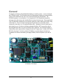
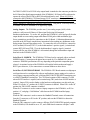
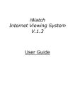
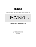
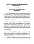
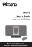
INTEGRATED SYSTEMS AND CONTROL, INC. User Manual PCM400A INTEGRATED SYSTEMS AND CONTROLS, INC. PCM400A Users Manual Integrated Systems and Control. Inc. PO Box 7682, Auburn, CA 95604 Phone 530-878-9038 • Fax 530-878-9137 Revised 3/28/2001 Table of Contents General Specifications Installation Operation Service 3 4 9 10 13 2 General To bring the advantages of the PCM1600 technology to smaller systems, we have developed the PCM400A system. The PCM400A shares the programming, logging and communications features of the PCM1600 with a lower I/O count and a built-in low cost Modem. The PCM400A product is a two board set. It is comprised of a CPU Board that contains the microprocessor and memory and virtually all the necessary electronic parts. The second board is the I/O Board that contains the screw terminals required to connect almost all the field wiring to the board set. The two boards are designed to be placed next to one another and be connected to each other via a 50 conductor ribbon cable. Alternately, the two boards may be placed apart by up to 36 inches to facilitate packaging flexibility, BUT care must be taken to keep the path of the cable away from electrically noisy equipment. The I/O Board contains a 20 pin ribbon cable connector that is designed to drive the “outputs-only” of either a RLY80 or RLY180 relay board. We believe that the PCM400A is a product that provides the best combination of software functionality, packaging flexibility, short development cycle and low cost. PCM400A CPU Board 3 PCM400A I/O Board 4 Specifications CPU Board Size: Height = 5.0”, Width = 8.8”, and Depth = 1.0”. I/O Board Size: Height = 2.2”, Width = 8.8”, and Depth = 1.0”. Input Power: 24VDC +-0.2 at 1.0 Amps (including (1) RLY180). The input power is fused at 1.25 Amps and there a power switch on the I/O Board to switch the main input power. The field terminals for connection of power are on the I/O Board (TB1). Output Power: Terminals are provided on the I/O Board for providing power for external sensors and output relays. A 12vdc terminal is available for external use of less than 50 milliamperes of current. A 24vdc terminal is available for powering external output relays when neither of the RLY relay boards is required. This 24vdc output is limited to a maximum current of .25 amperes. Analog Inputs: The basic board set has terminals for 6 analog inputs which may be used as either 0-5VDC, 0-20ma, 4-20ma, or 10K Thermistor temperature. A board jumper may be used to connect the input to a 250 Ohm 1% resistor for 0-20ma or 4-20ma inputs. In addition to the 6 analog inputs available for field sensors, there are two analog inputs that are used internally to monitor power supply voltages. Two Analog Inputs are reserved for measuring the system power supplies. AI#7 measures the 5 vdc supply voltage and AI#8 measures the 24 vdc supply voltage. The CPU Board is equipped with a 10 pin ribbon connector that allows the connection of one Expansion Analog Input Board to allow the addition of 8 more analog inputs (AI#9 thru AI#16). Therefore, the maximum number of field accessible analog inputs with an expansion board is 6+8=14 field useable analog inputs. Digital Inputs: The basic board set has 8 digital inputs (DI#1 thru DI#8) which are selfpowered from the 24VDC power such that only a contact closure is required to activate them. Screw terminals on the I/O Board are provided for connections. Internally these inputs may be defined for use as general purpose inputs, status inputs intended to trigger alarms if the corresponding digital output does not switch, or as a timed latching input useful in logic rules to provide temporary user overrides. When a RLY80 or RLY180 relay boards are attached to the PCM400A, the digital status inputs of the relay board are IGNORED. All the field digital input devices must be terminated on the I/O Board. There is currently no way to expand the number of digital inputs. Digital Outputs: The basic board set has 8 solid state (sinking) 24VDC digital outputs terminated on the I/O Board (DO#1 thru DO#8). Each output is capable of sinking (switching to RET) a load device that requires 100ma or less. A typical load would be an interface relay with a 24VDC coil or another logic board that may use a pulse-width modulation signal to control air pressure, etc. By programming the PCM400A any or all of the 8 DO’s may be used 5 for PWM. If a RLY80 or RLY180 relay output board is attached to the connector provided on the I/O Board, the digital output terminals of the PCM400A’s I/O Board will be redirected to operate the relays of the RLY80 or RLY180 and should not be used. When a RLY180 is connected to the PCM400A, CPU Board jumper JU15C must have a shunt installed to inform the software that this special board is present. This jumper must be removed when no relay board is attached or when the RLY80 relay board is used. Using the RLY180 relay board, the PCM400A can drive a maximum of 18 digital relay outputs. Analog Outputs: The PCM400A provides one (1) true analog output (AO#1) which produces a self-powered 0-20ma or 4-20ma signal for driving field mounted transducers/transmitters. To use the AO, program the PCM400A’s AO#1 and specify that the output should use a true analog output rather than a PWM (pulse width modulation) type. Screw terminals are provided for connections on the I/O Board. Calibration adjustments are provided on the I/O Board, consult factory instructions before making any adjustments on the analog output Zero and Span adjust screws. To connect the AO to a load devise, connect the AO#1 terminal (I/O board, TB2- 12) to the load/transducer’s positive signal (+) terminal and connect RET (I/O board, TB2- 32) to the load/transducer’s negative signal (-) terminal. Current will flow out of the PCM400A’s AO terminal, through the load/transducer input and then back to the PCM400A’s RET. Serial Port #1, MODEM : The PCM400A CPU Board can be equipped with an on-board MODEM option. Connection to the phone line are made by J5, a standard RJ11 phone connector. MODEM specifications will vary depending on the particular component option selected. An optional version of the PCM400A will omit the built-in modem and supply a RS232 port connector, J4, for connection to a external Modem or other device. Serial Port #2, RS232/RS422/RS485: The PCM400A CPU Board contains a multipurpose serial port that can be reconfigured by software and hardware jumper settings to be used as a service laptop computer interface port, a full time RS422 IWATCH/ILISTEN monitoring port or a RS422 Handheld Terminal port. The CPU Board contains a DB9 connector (J3) used when a RS232 interface is required, and a terminal strip (TB1) used when a RS422 interface is required. Jumper JU8 is used to further set the hardware configuration to use this serial port. When JU8 is in the “A” position, the J3, RS232 connector is enabled. When JU8 is in the “B” position, the TB1, RS422 connector is enabled. When the J3 connector is used to connect a laptop computer to the PCM400A, set JU8 to position “A”, and plug a “Null Modem” cable between the PCM400A and the laptop computer. When the TB1 connector is used to connect the Handheld Terminal, remove all connections from the J3 connector, set JU8 to the “B” position, and reset the PCM400A to detect the Handheld Terminal. When the TB1 connector is used to connect a full time IWATCH/ILISTEN equiped computer to the PCM400A, JU8 should be set to “B”, and a DB9 female connector with pins 7 and 8 6 shorted together, should be plugged into the otherwise unused J3 connector (to select a computer type interface). 7 Installation PCM400A Summary of Connections The terminal strips of the PCM400A board set are mainly located on the I/O Board. Connections for serial port/MODEM and the expansion connector for the use of the Expansion Analog Input Board are located on the CPU Board for electronic reasons. The following tables define the function of each of the PCM400A’s connections: CPU Board:___________________________________ TB1 (Serial Port #2, RS422) 1 - Tx+ 2 - Tx3 - Rx+ 4 - Rx5 - COM 6 - 5vdc J1 (I/O Board connections) J2 (Analog Expansion for AI#9 to AI#16) J3 (Serial Port #1, RS232) 1 - CD 2 - RX DATA 3 - TX DATA 4 - DTR 5 - COM 6 - n/u 7 - RTS 8 - CTS (this input must be asserted to select the computer interface protocol) 9 - n/u J4 (OPTIONAL USE ONLY, Serial Port #1, RS232) 1 - CD 2 - RX DATA 3 - TX DATA 4 - DTR 8 5 - COM 6 - n/u 7 - RTS 8 - CTS 9 - n/u J5 (Serial Port #1, MODEM, RJ11 Telephone Connector) 1 - n/u 2 - n/u 3 - TIP 4 - RING 5 - n/u 6 - n/u Jumpers used to configure the CPU Board for hardware related features: JU1 - Install to enable the battery support for the memory. Remove for shipment. JU2 thru JU7 - Factory configured, DO NOT CHANGE. JU8 - 2-pos jumper for Serial Port #2 configuration, A=RS232, B=RS422. JU9 - 2-pos jumper for AI#1, A= 5vdc or Thermistor, B= 20ma. JU10 - 2-pos jumper for AI#2, B= 20ma, A= 5vdc or Thermistor. JU11 - 2-pos jumper for AI#3, B= 20ma, A= 5vdc or Thermistor. JU12 - 2-pos jumper for AI#4, B= 20ma, A= 5vdc or Thermistor. JU13 - 2-pos jumper for AI#5, B= 20ma, A= 5vdc or Thermistor. JU14 - 2-pos jumper for AI#6, B= 20ma, A= 5vdc or Thermistor. JU15A - (future) JU15B - (future) JU15C - Install for use with RLY180 relay board, remove for RLY80 or none. I/O Board:___________________________________ TB1 (power input terminal strip) 1 - 24VDC (regulated) main input terminal. 2 - DC RET (return for power supply) 3 - DC RET (return for power supply) TB2 (I/O Terminations) 1 - AI#1 2 - AI#2 3 - IRET 4 - AI#3 5 - AI#4 6 - IRET 7 - AI#5 8 - AI#6 9 9 - IRET 10 - Thermistor 5VDC power supply 11 - Thermistor 5VDC power supply 12 - AO#1 4-20ma Output 13 - 12VDC sensor power (50 ma max) 14 - 12VDC sensor power (50 ma max) 15 - 24VDC power (switched, 0.25A max) 16 - 24VDC power (switched, 0.25A max) 17 - DO#1 18 - DO#2 19 - DO#3 20 - DO#4 21 - DO#5 22 - DO#6 23 - DO#7 24 - DO#8 25 - DI#1 26 - DI#2 27 - DI#3 28 - DI#4 29 - DI#5 30 - DI#6 31 - DI#7 32 - DI#8 33 - RET 34 - RET 35 - RET 36 - GREEN WIRE GND J1 (CPU Board connection) J2 (RLY80/RLY180 connection) 10 Installation Scaling Analog Inputs When scaling a sensor, the minimum/maximum scaling values must be calculated. The minimum and maximum scaling values entered into the Analog Input Definition represents the values that are represented when 0 volts and 5 volts, respectively, are measured at the analog input terminal. The simplest method to calculate the proper scaling values for typical sensors are shown below in several examples. Example 1: A 4-20ma liquid level sensor is to be scaled. The sensor operates over a range of 0 to 15 feet of liquid, where 4ma=0 feet and 20ma=15 feet. The simplest way to scale a 4-20ma sensor is to take the range of the sensor, divide it by 4, then subtract the result from the 4ma sensor value. V4 = level value at 4ma sensor output V20 = level value at 20 ma sensor output Minimum Scale Value = V4 - (V20 - V4)/4 = 0 - (15 - 0)/4 = 3.75 feet Maximum Scale Value = V20 = 15.0 feet Example 2: A 0-5VDC voltage type liquid level sensor is to be scaled. The sensor operates over a range of 0 to 15 feet, where 0.7 volts=0 feet and 4.2 volts=15 feet. Note that voltage sensors are not neatly calibrated at the factory for standard voltage values. The calculations required are as follows. M = slope of voltage vs depth in volts per feet (or inches or whatever) Vdry = voltage output of the sensor when removed from the liquid. Vx = voltage at some known depth, Dx. Dx = some known depth at which Vx can be recorded (usually sensor maximum). Minimum Scale Value = the minimum value to enter into TRINET’s definition. Maximum Scale Value = the maximum value to enter into TRINET’s definition. M = (Vx - Vdry)/Dx = (4.2 - 0.7)/15 = 0.23 Maximum Scale Value = (5.0 - Vdry)/M = (5.0 - 0.7)/0.23 = 18.7 feet Minimum Scale Value = -Vdry/M = -0.7/0.23 = -3.0 feet 11 Operation PCM400A Operation and Programming The idea behind the PCM400A design is to combine the programming features of the SAC160/PCM1600 Masters with reduce hardware and more flexible packaging. The following paragraphs describe the main differences between the SAC160/PCM1600 programming and the PCM400A’s. Programming considerations of the PCM400A compared to the PCM1600 The firmware revision of the PCM400A is currently V4.16x. The development of programs must be done with the appropriate (v4.16x) Simulator software. Programs written for the PCM1600 or the MSTxxx series TriNet’s WILL NOT directly load into a PCM400A board or Simulator program without significant changes. Six (6) Analog Inputs are available on the basic board set; AI#1 thru AI#6. AI#7 is used internally to monitor the 5vdc power supply. AI#8 is used internally to monitor the 24vdc power supply. AI#9 thru AI#16 may be defined when the Expansion Analog Input Board is installed. If the Analog Input Expansion Board is installed, it must be mounted close (<10 inches) to the CPU Board. There are 8 definable Digital Inputs (DI#1 thru DI#8) in the PCM400A. The action and programming options of the Digital Inputs are compatible with the PCM1600. The input terminals located on either the RLY180 or RLY80 boards are not used and are IGNORED by the PCM400A. All DI’s must be terminated at the I/O Board. The single Analog Output is definable as in the PCM1600 with the option provided for AO#1 of either true analog or PWM. Unlike the PCM1600, the PCM400A DOES NOT support the use of a UMX-8 output multiplexer board attached to the Analog Output. Digital Outputs, DO#1 thru DO#18 are definable in the PCM400A. If the RLY180 board is attached, all the DO’s are available at the terminal strips of the RLY180. Otherwise, only DO#1 thru DO#8 are useable and are available at the I/O Board’s terminals or the RLY80’s terminals, if used. The Alarm and Activity logs have been redesigned from those of the PCM1600’s. The new Alarm Log now includes a “value” parameter that is used to store the value of a failed device that caused the alarm to be recorded. For instance, when an Analog Input exceeds it’s 12 programmed alarm limits, the value that exists at the time the log entry is opened is stored in the “value” parameter. Simple user logons via MODEM or local terminal are no longer saved in the Alarm Log but are now saved in the Activity Log. The Alarm Log now has a DIF formatted report that may be retrieved by IWATCH. The Activity Log now also has a “value” column that will be increasingly used in the future. The Activity log report has been redesigned in both the ASCII and DIF formats. In addition, when retrieving the logs, you have 3 choices. First you may retrieve the activity for any single point without any other general activity that is not directly related to the specified point. Secondly, if you specify a point# of 0 (zero), you will get a report of activity for all points without any other general activity that is not point related. Lastly, specifying a point of “999” will retrieve only “General” activity items such as user logons (via Modem or other), DI activity, etc. The logs may only be cleared in three circumstances. First, you may clear the logs manually by invoking a menu selection or by an Abbreviated Command. Secondly, if the software detects a flaw that really will prevent the logs from being used (added to and displayed) the log will be cleared and the Alarm Log will receive an entry reflecting a “Log Corrupt” condition. Furthermore, if a corruption occurs due to a memory failure, noise induced processor malfunction, or other hardware problem will be detected if possible and an Alarm Log entry be made. A Corruption detected “on the fly” will cause an Alarm Log entry but the log will not be cleared automatically, but left to the user to clear manually. Thirdly, loading new programming via MODEM or via load from backup will only result in clearing the log if the definition being loaded changes the size of the log or if the operand types included in the log columns changes, adds a column or deletes a column. The User Log(s) and the Maintenance Log may now be loaded similarly to loading the programs. This may be done by using IWATCH (v2.50A or higher), ILISTEN (v1.00B or higher). We have also developed a Windows ’95 utility program named “ILogEdit.exe” that will convert User log and Maintenance log files to and from TriNet format and Excel format files so that the logs may be edited. This ability is designed to allow the restoring of a User Log (maybe only one of 32 possible logs) after a program upgrade so that a table of values can be maintained or some previous history data restored when a failure has occurred. Requesting a User Log, XMODEM, DIF report of a User Log will result in a file with the correct header, named by default as UG.DIF. The default Maintenance Log DIF report file is named “MG.DIF”. Note that these log files do not contain the log definitions but only the data from the log, so that a complete restoration requires that the correct UL.DIF as well as the correct UG.DIF files be loaded in that order. See further information regarding the loading of log files in the documentation for IWATCH and ILISTEN. The PCM400A may optionally, be equipped with an on-board 2400 Baud MODEM. The 2400 baud MODEM does NOT have the ability to have different analog Baud rates and Host Baud rates like the PPI external modems we use on many of our systems. This means that if the Serial Port Baud rate is set at 2400, the MODEM must only be called by a computer that has it’s MODEM Baud rate set at 2400 or higher. If a calling computer has it’s port set at 1200 Baud, the PCM will answer and lock tones at 1200, but since the hardware Host Baud rate internal to the PCM is set at 2400 Baud, a speed mismatch will result in garbage being sent and 13 received. You may set your computer to a baud rate above 2400, and logon successfully because the calling MODEM will discover that the PCM can link at no higher than 2400 and will step down to that speed. I have noticed that sometimes, if the phone line is cut by the caller just hanging up without doing the “C” hang-up process for the PCM, that the MODEM may not drop the line until the PCM discovers that no activity has occurred for 10 minutes and forces the MODEM to drop the line. This must be a shortcoming with the MODEM where a loss of carrier is not always detected properly or the time limit on the carrier dropping is set at the factory to a large value. Only experience will determine whether this is a problem. If one always does the “C” hang-up command, the PCM is ready to accept another call immediately. The PCM400A may optionally be equipped with an on-board high speed 14400 or 28800 Baud MODEM. If one of these high speed MODEM’s are installed, the Host Baud rate may be different that the Analog Baud rate transmitted over the phone lines. These MODEMs work exactly like the external MODEMS such as the PPI models we use on many products and the cautionary notes above regarding the on-board 2400 Baud MODEM’s do not apply. To connect ISAC’s Handheld Terminal device to the PCM400A’s TB1 (CPU Board), a special cable is needed. This cable may be obtained from ISAC, but the cable connections are described below for reference. Handheld Term RJ11 1 2 3 4 5 6 PCM400A CPU TB1 6 1 3 2 4 5 The Handheld terminal has five programmable function keys that should (if not already done at the ISAC factory) be programmed to give the functions necessary to control the Handhelds cursor and screen funtions. These keys may be programmed by pressing the CTRL, SHIFT and F2 keys together, and then selecting the key to program and changing the code that the key code that will sent when the key is pressed by the user. The terminal function keys should be set for: Handheld Term F key F1 F2 F3 F4 F5 Hex Code 1B (Escape key code) 1A (Page Down key code) 17 (Page Up key code) 1B (Escape key code) 09 (Tab key code) 14 Service For service, contact ISAC Inc., through the following routes: Integrated Systems and Control, Inc. PO 7682 Auburn, CA 95604 Ph: 530-878-9038 Fax: 530-878-9137 Email: [email protected] 15