1
High Voltage Variable
Frequency Speed Control
System
User Manual
Shenzhen INVT Electric CO., LTD.
1
Contents
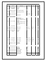
Chapter 1 Precautions···················································································································· 5
1.1 Safety notes······························································································································5
1.2 Relevant design standards of the high voltage variable frequency speed control systems ········· 6
Chapter 2 Product Overview ········································································································· 8
2.1
Technical features···············································································································8
2.2
Brief introduction of features······························································································9
2.3
Product application fields ································································································· 11
2.4
System composition and principle of work ······································································· 11
2.4.1 System composition·········································································································· 11
2.5
Public technical parameters, specifications and models ···················································· 13
2.5.1 Model description············································································································· 13
2.5.2 Descriptions of data plate models ····················································································· 13
2.5.3 General parameters of the system ····················································································· 14
2.6
System profile and size parameters··················································································· 15
2.6.1 System profile ·················································································································· 15
2.6.2 System size parameters····································································································· 16
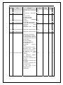
Chapter 3 System transportation, storage and waste disposal ················································· 20
3.1
The transportation of high voltage variable frequency speed control systems ··················· 20
3.2
Arrival acceptance check·································································································· 20
3.3
Storage and conditions······································································································ 21
3.4
Storage of spare parts ······································································································· 21
3.5
Product waste treatment···································································································· 21
Chapter 4 System Installation and Wiring················································································· 22
4.1
Installation of cabinet bodies ···························································································· 22
4.2
Installation of the high voltage parts················································································· 25
4.3
Wiring of user terminals ··································································································· 27
Chapter 5 System debugging and running ················································································· 31
5.1
Items of detection and confirmation before debug running ··············································· 31
5.2
Tests of Control cabinet power on and after power-on······················································ 31
5.3
Main loop power on and power-on debugging·································································· 32
5.4
Test with motors··············································································································· 33
Chapter 6 Operation of the variable frequency speed control system····································· 34
6.1
Description of switch cabinet ··························································································· 34
6.2
Operation steps of variable frequency speed control system ············································· 35
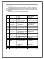
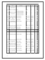
Chapter 7 Human-machine interface ························································································· 37
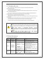
7.1 Keyboard··························································································································· 37
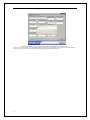
7.2 Touch screen ····················································································································· 41
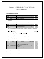
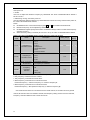
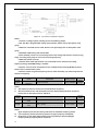
Chapter 8 Detailed Functional Description················································································ 44
Chapter 9 Warning information and fault solution··································································· 85
9.1 Fault and trouble shooting ································································································· 85
9.2 Unit fault ··························································································································· 87
9.3 The action after fault ········································································································· 88
9.4 Action after warning·········································································································· 88
2
9.5 Common Faults and Solutions··························································································· 89
Chapter 10 Maintenance·············································································································· 90
Appendix 1····································································································································· 93
Appendix 2····································································································································· 95
Appendix 3··································································································································· 103
3
Introduction
Thank you for purchasing the high voltage variable frequency speed control system of our company. CHH Series
high voltage variable frequency speed control systems are the multilevel high voltage variable frequency speed
control systems manufactured by our company, and are applicable to 3-phase high voltage induction motors. Please
read and comprehend the contents stated in this manual before use to ensure proper usage. Improper usage will result
in abnormal running or the reduction of the service life.
This user manual is only applicable to the CHH Series High voltage variable frequency speed control systems of our
company.
Please keep this manual with the variable frequency speed control system under safe custody for use whenever it is
necessary.
4
Chapter 1 Precautions
1.1 Safety notes
Notes
Before installation, wiring, running and maintenance inspections, you are required to get well
acquaintance with the contents of this instruction manual, to ensure the proper using. It is also
necessary to be familiar with the circumstances of the driven machinery and all relevant safety
notes while using.
About usage
Notes
The high voltage variable frequency speed control systems of this series are only applicable to
3-phase high voltage induction motors, and cannot be put into other applications, as it would result
in danger.
Under the circumstances of application where the failure of this product may cause accidents or
loss, corresponding safety measures must be provided for emergencies.
About wiring
Notes
A high voltage circuit breaker must be equipped at the power supply side of the high voltage
frequency inverter for circuit protection.
Reliable grounding is required.
The wiring must be implemented under the guidance of the professionals of our company,
according to the relevant electrical safety standards.
The main body of the equipment must be installed in place before the wiring operations.
It is required to confirm the consistency of the phase number of the input power and the rated input
voltage with the ratings of the frequency inverter.
The output terminals (U, V and W) must not be connected to AC power supplies.
About disposal
Warning
The discarded parts and components shall be disposed of as industrial waste.
About handling
Warning
5
While moving, transporting and placing the equipment, the location of the equipment shall be kept
level and flat.
While lifting the equipment, adequate lifting strength is required, with gentle liftings and landings.
Please do not drop (leave) any thread, paper, metal fragments, tool or other foreign matters in the
variable frequency speed control system.
If any part of the variable frequency speed control system is damaged, please do not install or use
the equipment.
Guard rails shall be put up at the necessary places (with High voltage danger signs on them), and
must not be removed during the operation.
About installation
Danger
It is required to configure the grounding lines strictly in accordance with the requirement of the
technical guidance in the manual and the national standard configurations.
The wiring operation must be carried out by professional electrical technicians.
The operation can only be carried out after confirming that the control circuit and the main
circuit both have no voltage input.
The I/O cables must be wired according to the instructions, and no error is allowed, otherwise
the equipment may be damaged.
Confirm that the input power supply complies with the requirement of the product technical
specifications.
The I/O lines must meet the requirement of insulation and capacity.
The variable frequency speed control system shall be installed onto flame-retardant matters, e.g.
metal stands, cement ground, etc.
Flammable objects shall not be placed inside the cabinet of the variable frequency speed control
systems or around them, including the equipment drawings, instruction manuals and others.
About operation
Warning
The variable frequency speed control system can be connected to the power supply only after the
electrical cabinet doors are all closed, and the cabinet doors must not be opened after the power
supply is connected.
The switch must not be operated with wet hands.
When trip and reboot occurs, the peripheral system specially designed shall be able to guarantee
personal and equipment safety.
When the variable frequency speed control system is switched on, even if it is in the stopping
status, the terminal may still be charged and must not be touched.
The start-stops of the high voltage frequency inverter shall not be operated using the methods of
connecting or disconnecting the main circuit.
1.2 Relevant design standards of the high voltage variable frequency speed
control systems
The design and manufacturing of CHH Series high voltage variable frequency speed control systems refer to the latest version of
national standards (GB or GB/T), the standards of International Electrotechnical Commission(IEC) and International System of
Units (SI) as the lowest design technical indices, as well as the requirements of the national standards (GB or GB/T) and the
standards of International Electrotechnical Commission(IEC) that the technical parameters of the relevant parts can meet.
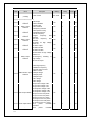
Part of the technical standards referenced by the design
IEC 76
Power Transformers
IEC 529
European (ECC) water protection specifications
IEC 1131/111 PLC
Correlative norms
IEC 68
Correlative tests
IEC68-2-6
Anti-vibration standards
IEC68-2-27
Anti-impact standards
IEC 1175
Design of signals and connections
IEC 801
Electro-magnetic radiation and anti-surge-interference
IEC 870
Communication protocol
IEC1000-4-2
ESD immunity test
IEC1000-4-3
RF radiation electromagnetic field interference-resistant test
IEC1000-4-4
First Transient/Burst Immunity test
IEC1800-3
Standards of EMC conduction and radiated interference
EN50082-2
General standards of industrial environment
IEEE519
Recommended practices and requirements for harmonic control in electrical system
6
89/336EC
NFPA 70
NFPA 77
OCMA NWGIREV2
ISO/IEC 11801
NEMA
GB 12326
GB/T 14549
GB 1094.1~1094.5
GB 6450
GB/T 10228
GB 17211
GB 311.1
DL/T 620
GB/T 3859.1
GB/T 3859.2
GB/T 3859.2
JB4276
GB/T
GB/T4064-1983
GB4028-1993
7
CE Mark
State Electrical Appliance Code
Recommended anti-electrostatic methods
Noise Level Norms
International electrical wiring
American National Electrical Manufacture Association
Quality of electric energy supply - Admissible voltage fluctuation and flicker
Quality of electric energy supply - Harmonics in public supply network
Power transformers
Dry-type power transformers
Specification and technical requirements for dry-type power transformers
Loading guide for dry-type power transformers
Insulation co-ordination for high voltage transmission and distribution equipment
Overvoltage protection and insulation coordination for AC electrical installations
Semiconductor convertors - Specification of basic requirements
Semiconductor convertors Application guide
Semiconductor convertors - Transformers and reactors
Technical specifications for the packing of power convertor
General specifications for packing of mechanical and electrical product
General guide for designing of electrical equipment to satisfy safety requirements
Degrees of protection provided by enclosures (IP code) and other relevant standards currently used
Chapter 2 Product Overview
2.1 Technical features
CHH Series high voltage variable frequency speed control systems are the voltage-source variable frequency speed control systems
of a new generation featuring direct output of high voltage designed and manufactured by our company, implementing a perfect high
voltage waveform output via the cascade of multi-level H-Bridge power units, and can directly drag the high voltage asynchronous
motors without the need of boosting, and without the necessity of additional installation of any wave filter; the harmonic index
complies with the most strict requirements of IEC (International Electrotechnical Commission) and GB (national standard) on grid
harmonic.
CHH Series high voltage variable frequency speed control systems are applicable to three-phase current motors under standard high
voltage (3kV, 6kV, 10kV), providing the following features:
1
Small content of input harmonic
CHH Series high voltage variable frequency speed control systems adopt trans-phase multiple rectifying technology on the
power supply side; the harmonic on the grid side has little pollution and high power index, meeting the requirement of GB
14549-93 standard and IEEE std 519-1992 power quality standard on the harmonic distortion of voltage and current, and will
not produce any harmonic interference to the other electrical equipment on the same grid.
2
Low output harmonic
CHH Series high voltage variable frequency speed control systems adopt the trans-phase multiple WDM technology on the
output side, with very little output harmonic, and can adapt to various kinds of motors without the necessity of output filter
equipment. Since the output voltage has low distortion and good sine degree of waveforms; the motor has low running noise,
small torque pulsation and low productivity of heat.
3
High power factor
CHH Series high voltage variable frequency speed control systems are of the constant voltage source type, and can maintain
high power factors in the full speed range, with the full load power factor of over 0.95, thereby reducing the issues of low
utilization rate of the users’ power transformer equipment and the power factor compensation on the user end caused by the low
power factors.
4
Strong voltage adaptability
The input voltage has strong adaptability, allowing the fluctuating of grid-side voltage between 10%~-10%. AVR function is
provided to automatically adjust the output voltage according to the fluctuation of the bus voltage.
5
Supporting smooth rebooting after power recovery
While running, after the instantaneous power interruption of the grid and the recovery of the running conditions of the
re-power-up system, if corresponding function codes are configured, then the system can be rebooted automatically after
power-up. If the start-up mode is set to Rotation speed tracking Start-up, then the high voltage variable frequency speed control
systems can automatically detect the rotation speed of the motors in 2.0 seconds, implementing no-impact reboot and
recovering the operation to the configured state, avoiding the impact caused by the interference of electricity and ensuring the
continuous operation reliability for the running of motor, thereby avoiding the loss caused by unnecessary shut-downs.
6
High reliance and convenient maintenance
The IGBT power module of CHH Series high voltage variable frequency speed control systems has the relatively large design
margin of voltage and current; the triggering and overcurrent protection of the IGBT module uses the specialized driver module
circuit, providing very high reliability.
CHH Series high voltage variable frequency speed control systems use optical fiber for the transmission of control signals, the
electrical cabinets and PCBs of all functions are provided with reliable electromagnetic shielding features.
CHH Series high voltage variable frequency speed control systems adopt the modular design of “Power electronic building
blocks” type for implementing the perfect structural process design, the unit-components of the same sizes are designed for
universality; if any failure occurs, they can be replaced with simple tools within a few minutes, very conveniently and easily.
7
Alarm and failure protection functions
CHH Series variable frequency speed control system provide abundant features of alarming and protections, wherein over 11
kinds of failure messages related to the power units are already provided, all of which can be examined using the function
codes in PD group.
If any failure occurs, the variable frequency speed control system can automatically record the information of the running
environment of the last 3 failures, and the touch screen can record more.
8
Power unit bypass features:
When any failure occurs to a certain power unit of the variable frequency speed control system, the power unit can be bypassed
through the bypass function, and the frequency inverter shall be derated for further running. Users can choose manual
bypassing or automatic bypassing of the unit by manipulating the function codes.
9
Soft boot, with no surge current
CHH Series high voltage variable frequency speed control systems have the Soft boot capability to which no other system can
compare. The start-up time shall be configured by the user. The internal function of over-current stall acceleration was also
provided for suppressing the impact current produced at the start-up of the motor, ensuring the safe running of the motor and
lengthening its service life, and to enable the rapid start-up of the grids and motors with no impact. This feature can also
effectively avoid the breaking of electric squirrel cage bar in the motor and other failures of motors.
8
10
11
12
Reducing motor abrasion, saving maintenance costs
Blower, pumps and other loads use CHH Series high voltage variable frequency speed control systems for adjusting the
rotating speed of the motor to adjust the output, which not only fulfills the objective of energy saving, but also significantly
reduces the mechanical abrasion of the motor and its loads, saving maintenance costs for the users.
Abundant user terminal interfaces
Standard CHH Series high voltage variable frequency speed control systems shall be equipped with abundant I/O ports:
3-channel analog inputs, 4-channel analog outputs, 16-channel digital inputs, 8-channel relay outputs, 1-channel high-speed
pulse input and 1-channel high-speed pulse output. All I/O ports are programmable, which facilitates the users to use these
ports to build up their own application system, and also guarantees the system has good extensibility.
Abundant human-computer interface features
The human-machine interaction of CHH Series high voltage variable frequency speed control systems adopt the dual
configuration of touch screens and digital keyboards, providing abundant functions of setting, display and operations and
friendly human-machine interface. Users can conveniently understand the running state information of the system via the
interfaces, and implement the control to the high voltage variable frequency speed control systems according to the
requirement of process control.
2.2 Brief introduction of features
1. Frequency settings
Supporting multiple ways for specifying the running frequency, such as:
1) Specifying by keyboard
2) Specifying by communication (the touch screen uses this scheme)
3) Specifying by analog signal inputs
4) Specifying by high-speed pulse
5) Specifying by adjusting the PID control: automatically adjusting the frequencies through the comparison of PID
specifying and feedback. This is particularly convenient when applied in constant pressure water supply systems.
6) Multi-stage speed specifying: multiple frequency bands and the acceleration/deceleration time can all be specified in the
variable frequency speed control system. These frequency bands can be switched flexibly by the selecting through the
terminals.
7) Also, for the flexibility of the control of running frequencies, CHH Series frequency inverters support 2 frequency sources,
either of which, or the combination of the sum, difference and maximum values of which can be selected to be used as the
actual running frequency.
Users can not only use the frequencies to control frequencies, but are also allowed to flexibly perform fine-tunings of increasing
or decreasing to the running frequency by pressing the up/down buttons or manipulating the digital terminals.
For the settings related to running frequency, please refer to the descriptions of the function codes in P0 Group.
2. Acceleration/Deceleration time
CHH Series high voltage variable frequency speed control systems support 4 groups of acceleration/deceleration time. Users can
choose the current acceleration/deceleration time by various combinations of the multi-functional terminals.
3. Running control methods
There are three different ways of starting up, meeting the application requirements on different occasions.
1)
Direct start-up;
2)
DC braking first, and then start (as for the fan-type loads, the inversion phenomenon exists; first ensure the rotating speed
of the motor to be zero by the DC braking, then start the motor, in order to avoid the rush current being generated while
starting up);
3)
Rotation speed tracking start-up: the variable frequency speed control system will firstly examine the current rotating
speed of the motor, and then directly start up based on it.
2 Ways of stopping:
1)
Deceleration stop,
2)
Free stop.
Supporting the selections of 3 different start-stop control command channels, including:
1)
Keyboard control
2)
Terminal control
9
3)
Communication control.
The settings of the start-up and shut-down of the variable frequency speed control system shall refer to the descriptions of the
relevant function codes in P1 Group; for the settings of the start-stop control command channels, please refer to the descriptions
of the function codes in P0 Group.
4. AVR function:
CHH Series high voltage variable frequency speed control systems can automatically adjust the duty cycle of the output PWM
signals according to the fluctuation of the bus voltage, thereby reducing the impact of the fluctuation of the grid voltage on the
output voltage. Users can choose whether to enable the AVR function in P0 Group.
5. Miscellaneous functions:
CHH Series variable frequency speed control systems support the settings of the inching function and the hopping frequency,
the usage of these functions is as follows:
1)
Inching function: This function is mainly used for debugging, and is capable of individually setting the inching frequency
and acceleration/deceleration time.
2)
Hopping frequency: CHH Series variable frequency speed control system can specify 2 hopping frequency points at most,
which are mainly used for avoiding the resonance points in the machineries, and preventing the equipment from being
damaged due to resonances.
For the information of the detailed settings, please refer to the relevant description of the function codes in Group P3.
6. Torque increase function controlled by V/F
CHH Series variable frequency speed control system provides the function of low-frequency torque increasing, which is mainly
used to solve the problems of lack of magnetic flux led by the voltage loss caused by stator resistors under low-frequency.
Users can specify the torque increase value and the speed range of the torque increase in the function codes in Group P4.
7. Selections of multiple V/F curves
CHH Series variable frequency speed control system provides multiple forms of V/F curves (e.g. multi-points V/F curves,
power of 1.3, power of 1.7, V/F curves to power of 2.0), with which various load requirements can be met. Users can choose
the suitable V/F curves among the function parameters in Group P4.
8. The configuration of programmable user terminals
Standard CHH Series high voltage variable frequency speed control systems are equipped with abundant I/O terminals, and the
terminals are all programmable, thereby guaranteeing the flexibility and extensibility of the system. For the detailed terminal
functions, please refer to the detailed specifications of the function codes in Group P5 and P6.
9. Real-time monitoring of running parameters
CHH Series high voltage variable frequency speed control systems provide abundant parameter monitoring functions. In the
running state, it is allowed to monitor the running frequency, given frequency, bus voltage, output voltage, output current,
running speed, output power, output torque, PID specifying, PID feedback, terminal state, analog input value and time.
In the stopping state, it is allowed to monitor the given frequency, bus voltage, terminal state, analog input value and the current
stage of the multi-stage speed.
Users can select the monitoring object to be displayed using the function codes, and can also examine the relevant parameters
with the touch screen. The monitoring objects are viewed by the keyboard via the relevant function codes in Group P7.
10. PID control
PID control function can realize the closed-loop application similar to the constant water supply; it provides flexible settings of
PID parameters to meet the requirements of the users on different occasions. For the details, please refer to the detailed
specifications of the function codes in Group P9.
11. Multi-stage speed control
For the systems requiring frequent speed changes, CHH Series variable frequency speed control system can provide the running
modes of multi-stage speed. Users can flexibly choose the speed stage currently used via the terminals. For the detailed settings
of multi-stage speed, please refer to the specifications of the function codes in Group PA.
12. Failure protection functions
CHH Series variable frequency speed control systems provide abundant functions for protection; some functions can be
flexibly configured through the parameters of the function codes, such as: over-voltage stall, over-current stall, loss-of-phase
detections, etc. For the details, please refer to the detailed specifications of the function codes in Group Pb.
The parameters in Group PD can also be configured to shield the failure information of certain power units.
The information of the running environment of the variable frequency speed control system at the times of recent 3 failures are
recorded in the parameters in Group P8, in the meantime, the failure information of the corresponding power units shall be
displayed in the function codes in Group PD.
CHH Series high voltage variable frequency speed control systems also support the alarming function. While alarming: system
uses acousto-optic prompts without shutdown, the system will automatically reset that alarm according to the fixed period of
time, users can select whether the alarming function is shielded and configure the reset interval time of alarming.
13. Modbus communication function
CHH Series variable frequency speed control systems provide the support of standard modbus communication protocols. Users
can use their own systems to implement the control and settings of the frequency inverter through modbus protocols, for the
detailed relevant information about modbus, please refer to the detailed description of the function codes in Group PC.
Note: The touch screen and the frequency inverter are connected by using modbus protocols; if the touch screen is used, users
will not be able to use modbus communication.
10
2.3 Product application fields
CHH Series high voltage variable frequency speed control systems are mainly applied to blowers and pumps and on other
occasions when a great amount of energy can be saved through speed control. The detailed applications are as follows:
Thermal power: draught fans, supply blowers, dust collecting fans, compressors, water supply pumps, mortar pumps, etc.
Metallurgical mining: draught fans, ventilation fans, dust collecting fans, sandpumps, descaling pumps, centrifugal feed pumps,
etc.
Petrochemical: draught fans, gas compressors, injection pumps, submersible pumps, main pipe pumps, boiler water supply
pumps, brine pumps, mixers, sqeezers, etc.
Cement manufacturing: kiln draught fans, raw meal grinding draught fans, pressure supply blowers, main dust collecting fans,
cooler dust collecting fans, cooler exhaust fans, preheating tower blowers, sorting device blowers, kiln gas blowers, etc.
Water supply and sewage treatment: sewage pumps, clear water pumps, mixed flow pumps, oxygen delivery blowers, etc.
Others: Drive mechanical devices, wind turbines, wind tunnels, etc.
2.4 System composition and principle of work
CHH Series high voltage variable frequency speed control systems adopt power unit series connecting technology, which not
only solves the problem of device withstand voltage, but also solves the problem of loop current, the trans-phase overlapping of
inter-level output voltage greatly improves the harmonic performance of the system output voltage and decreases the du/dt of
the output voltage, lowering the input side harmonics through current multiple technology, and reducing the harmonic pollution
to the grids,
The main control part of CHH Series high voltage variable frequency speed control systems use Digital Signal Processor (DSP)
as the control core, supplemented by SLSI programmable logic devices (FPGA), analog input (AI), analog output (AO), digital
input (SI), relay output (RO) units.
The human-machine interfaces are composed of digital keyboards and touch screens.
The control signals of the main control part and the unit control part are transmitted through optical fiber, effectively avoiding
electromagnetic interference and guaranteeing the reliability of the transmission of the system control signals.
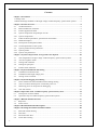
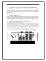
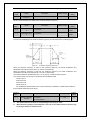
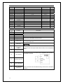
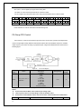
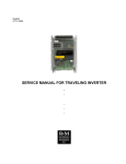
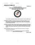
2.4.1 System composition
The overall structure of a high voltage variable frequency speed control system of CHH Series is composed of trans-phase
transformer cabinets, power unit cabinets and control cabinets, manual switching cabinets and automatic switching cabinets can
also be equipped according to the user’s requirements while in actual use.
Optional parts
选
配
部
分
Manual switch
手动切换柜
cabinet
Automatic switch
自动切换柜
cabinet
Transformer
变压器柜
cabinet
Power unit cabinet
功率单元柜
Figure 1 Outline schematic drawing of the frequency inverter
11
Control
cabinet
控制柜
1.
Trans-phase transformer cabinet
The cabinet is equipped with a trans-phase transformer on the inside, the trans-phase transformer adopts the dry-type structure, with
the insulation level of Level-H; it also adopts the connection method of trans-phase prolonged edge delta, reducing the grid-side
harmonics of the high voltage variable frequency speed control system. The basis of the trans-phase transformer is connected to the
load-bearing framework of the cabinet body through screw bolts.
The input of the trans-phase transformer cabinet is 3-phase high voltage (through the switch cabinet). The output of the trans-phase
transformer cabinet is 3-phase low voltage signals forming certain electrical angle between each other after the shape alteration of the
prolonged edge delta, each of the signals shall be separately connected to the input side of the power unit of each phase.
The trans-phase transformer cabinet can monitor the temperature of the phases of the trans-phase transformer in real time, and
provide the functions of overheating alarm and failure protection. The default configuration of the system is that when the
temperature of the trans-phase transformer is over 130℃, the system will prompt an alarm message but will not stop; when the
temperature is over 150℃, the system will start the over-temperature failure protection and freely stops.
2.
Power unit cabinet
The power unit cabinet is used for placing power units; the main control cabinet uses fiber communication to control the actions of
the power units. Every power unit is pushed in through the front door of the power unit cabinet and fixed on the power unit cabinet
with screws (fixed through the FRP on the rear or under the rear). The parts of output voltage and current detections shall also be
placed into the power unit cabinet.
The input of the power unit cabinet is the output of the trans-phase transformer; the output signal from the power unit on each phase
shall be connected in series one after another to establish a 3-phase voltage output to be connected to the switch cabinet, in order to
control the operation of the motor.
The Input 3-phase electricity of the power unit shall be wired through the backdoor of the power unit cabinet; the output of the
3-phase power unit shall be separately connected using copper bars, connecting the connecting terminal on the side close to the
trans-phase transformer cabinet in to the switch cabinet (or lead-in cabinet) through cables; connecting the starting points of the 3
phases on the side close to the main control cabinet together with copper bars to establish the midpoint of a star-shaped connection.
The power unit cabinet is used for installing and placing high-voltage power units, the power unit uses an H-bridge structure, the
output side is directly connected in a series, composing the high voltage output of the high voltage frequency inverter. The input of
the power unit is 3-phase rectifying input, which corresponds to the output of the trans-phase transformer. The control panel interacts
with the power unit through the signals of optical fibers, the main transmission signal is the drive signal, failure and alarm signals and
other control signals of power units.
The output current detection Hall and the rotating speed tracking circuit board are installed in the interior of the power unit cabinet.
3.
Control cabinet
The control cabinet is the brain of the entire variable frequency speed control system. It uses a separate UPS for power supply. The
UPS has 2 channels of power input (main and standby power supply), when the main power supply is invalid, the system will
automatically switch to the standby power supply. When the UPS is broken but one channel of the main standby power supply is still
valid, the electricity for the control cabinet will be provided by the main standby power supply. When the UPS or one channel of the
main standby power supply fails, the system will prompt an alarm, which ensures that the system can be used in the worst power
supply environment.
The input signals of the control cabinet are: the contactor state signal of the switch cabinet (according to the configuration), I/O
voltage, current detection signals, the feedback signal of each power unit and the users operation via the human-machine interface,
etc.
The output signals of the control cabinet are: the control signal of the power units (optical fiber), the control signal of the fans and the
contactor control signals of the switch cabinet.
Touch screens, keyboards and other human-machine interfaces area all installed on the control cabinet.
The programmable terminals open to users for using are also installed on the control cabinet.
4.
Switch cabinet
CHH100 Series of the high voltage frequency inverter provide standard switch cabinets for users to select. The switch cabinets
mainly realize the functions below:
User I/O connection terminals; power frequency/variable frequency conversion function; relevant affiliated electrical protection
measures; in the meantime, the insulation of the trans-phase transformer with the distribution system is also provided.
The input of the switch cabinet is the users’ 3-phase high voltage distribution; it shall be connected to the trans-phase transformer via
KM1 (QS1).
The output of the switch cabinet is the 3-phase frequency conversion output of the power unit cabinet; it will be directly connected to
the motor via KM2 (QS2).
The switch cabinet also provides the power frequency bypass contactor KM3, once any failure occurs to the frequency inverter, users
can directly switch the motor to the state of power frequency via the vacuum contactor KM3 to effectively guarantee the consistent
running of the system. Inside the switch cabinet, KM2 (QS1) and KM3 (QS2) implement the interlocking through logic.
The voltage and current transformers are installed inside the switch cabinet to provide the actual input voltage and current
information to the control cabinet.
12
High-voltage bus
High voltage bus
Automatic switch
cabinet
Manual switch
cabinet
User switch
User switch
KM1
QS
1
High voltage
KM3
Variable frequency
speed control
system
High voltage
variable frequency
speed control
system
KM3
CHH100
QS
2
CHH100
KM2
M
M
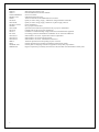
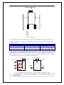
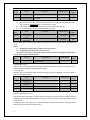
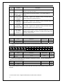
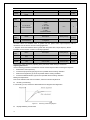
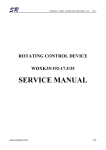
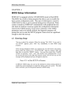
Figure 2 Schematic drawings of Manual and automatic switch cabinets
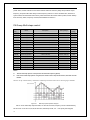
As shown in the drawing above, this is a typical configuration of switch cabinets, wherein the QS1 and QS2 are the manual knife
switches; the KM1, KM2 and KM3 are the vacuum circuit breakers. Users can choose to use manual switch cabinet or automatic
switch cabinet as needed.
2.5 Public technical parameters, specifications and models
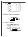
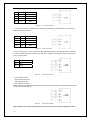
2.5.1
Model description
Number of power
units
High voltage
frequency inverter
Voltage grade
1st generation V/F
control
Universal products
Power grade
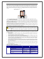
Figure 3 Product model definition of CHH Series frequency inverters
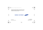
2.5.2
Descriptions of data plate mo
Company name
Model number
Power
Input specification
Output specification
Bar code
SHENZHEN INVT ELECTRIC CO.,LTD
MODEL:CHH100-100-10-8
SPEC:V1
POWER:1000kW
INPUT:AC 3PH 10KV ± 10%
50/60HZ
OUTPUT:71A
0~120HZ
AC 3PH 0~10KV
Bar code
MADE IN CHINA
Figure 4 Data plate of the high voltage frequency inverter
13
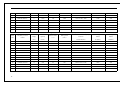
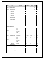
2.5.3
General parameters of the system
Items
Technical specifications
Rated capacity
236KVA~9000KVA
Rated power
185KW~7100KW
Input voltage
3/6/10KV±10%
Input frequency
50/60Hz±10%
Number of power units on
each phase
3 or 4 of 3KV; 5 or 6 of 6KV; 8 or 9 of 10KV
Input power factor
>97% (under rated load)
System efficiency
>96% (under rated load)
Output frequency
0~120HZ (continuously adjustable)
Output voltage
0~rated input voltage
Overload capacity
120% rated current protection for 60s; 150% rated current protection for 1s
Control interface
touch screen 、keyboard
Acceleration/deceleration time
0.1~3600S can be set up.
Control characteristics
V/F control, multiple V/F curves are available to be selected
High/low voltage insulation
method
High and low voltages are insulated by optical fiber
Communication
RS485 physical ports, supporting modbus standard communication protocols
Switch input
16-channel digital inputs
Switch output
8-channel relay outputs
Analog input
Analog output
3-channel analog input terminals AI1, AI2, AI3
AI1, AI2: 0~10V/0~20mA, AI3: -10V~10V
4-channel analog output AO1~AO4, output range:
AO1, AO2: 0~10V, AO3, AO4: 0~10V/0~20mA
High-speed pulse input
Range: 0~50KHz
High-speed pulse output
Range: 0~50KHz
Noise level
< 75dB
Harmonics
Protection functions
Meeting the requirements of national standard GB 14549-93 and IEEE 519-1992
power quality standards.
Overvoltage protection, undervoltage protection, overcurrent, overtemperature,
overspeed, external faults, etc.
Protection level
IP20
Cooling method
Forced-air cooling
Indoors, altitude of below 1000m (the higher altitude shall be used after derating
Using environment
with additional correction factor), no corrosive, explosive gas or dust, no direct
sunlight, etc.
14
Ambient temperature
-10℃~+40℃ (>40℃, additional installation of forced-air cooling unit)
Ambient humidity
5~95%, no gel
Vibration
5.9m/s2
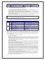
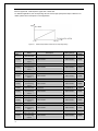
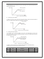
below 0.5g
m
Figure 5 Relation chart of the altitude and derating index
2.6 System profile and size parameters
2.6.1 System profile
D1
W3
W2
H2
H
H1
W1
Switch
Manual
Switch Cabinet Automatic
手动切换柜
自动切换柜
Cabinet
Transformer
变压器柜
Cabinet
W4
Power Unit
功率单元柜
Cabinet
Control
Cabinet
控制柜
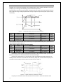
Figure 6 Outline structural chart of the high voltage frequency inverter
Figure 7 Inner schematic drawing of the high voltage frequency inverter
15
D2
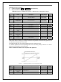
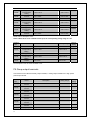
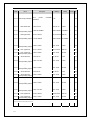
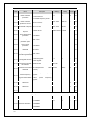
2.6.2 System size parameters
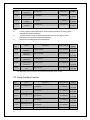
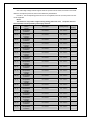
Table 1 of the Basic parameters of CHH100 Series of frequency inverter (3kV)
Outline dimension of frequency
Size of Manual
Size of automatic
inverters
bypass cabinet
bypass cabinet
W2×H×D(mm)
W1(mm)
W2(mm)
200
4100×2400×1200
900
60
250
4350×2400×1200
900
400
75
315
4350×2400×1200
900
3
500
95
400
4350×2400×1200
900
CHH100-0500-03
3
600
116
500
4350×2400×1200
900
6
CHH100-0630-03
3
750
150
630
4350×2400×1200
900
7
CHH100-0800-03
3
980
185
800
4950×2700×1200
900
8
CHH100-0900-03
3
1100
210
900
4950×2700×1200
900
9
CHH100-1000-03
3
1250
230
1000
4950×2700×1200
900
10
CHH100-1250-03
3
1500
300
1250
4950×2400×1200
900
11
CHH100-1400-03
3
1700
330
1400
4950×2700×1200
900
12
CHH100-1600-03
3
1900
370
1600
4950×2700×1200
900
13
CHH100-1800-03
3
2000
420
1800
6250×2700×1500
900
14
CHH100-2000-03
3
2700
460
2000
6250×2700×1500
900
15
CHH100-2240-03
3
3000
520
2240
6250×2700×1500
900
16
CHH100-2500-03
3
3300
600
2500
7200×2700×1500
900
17
CHH100-2800-03
3
3700
650
2800
7200×2700×1500
900
Rated
Rated
voltage
capacity
( kV )
( kVA )
CHH100-0200-03
3
2
CHH100-0250-03
3
Rated current
Motor power
(A)
( kW )
250
48
3
315
CHH100-0315-03
3
4
CHH100-0400-03
5
Serial
Frequency inverter
NO.
model
1
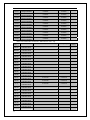
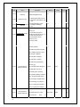
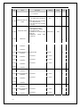
Table of the Basic parameters of CHH100 Series of frequency inverter (6kV)
16
Outline dimension of frequency
Size of Manual
Size of automatic
inverters
bypass cabinet
bypass cabinet
W2×H×D(mm)
W1(mm)
W2(mm)
185
3900×2700×1200
1000
900
25
200
3900×2700×1200
1000
900
280
27
220
3900×2700×1200
1000
900
6
315
30
250
3900×2700×1200
1000
900
CHH100-0280-06
6
350
33
280
4300×2700×1200
1000
900
6
CHH100-0315-06
6
400
37
315
4300×2700×1200
1000
900
7
CHH100-0355-06
6
440
42
355
4300×2700×1200
1000
900
8
CHH100-0400-06
6
500
48
400
4300×2700×1200
1000
900
9
CHH100-0450-06
6
560
54
450
4300×2700×1200
1000
900
10
CHH100-0500-06
6
600
60
500
4300×2700×1200
1000
900
11
CHH100-0560-06
6
690
67
560
4300×2700×1200
1000
900
12
CHH100-0630-06
6
750
75
630
4300×2700×1200
1000
900
13
CHH100-0710-06
6
880
84
710
4300×2700×1200
1000
900
14
CHH100-0800-06
6
980
95
800
4300×2700×1200
1000
900
15
CHH100-0900-06
6
1100
106
900
5100×2700×1200
1000
900
16
CHH100-1000-06
6
1250
118
1000
5100×2700×1200
1000
900
17
CHH100-1120-06
6
1370
132
1120
5100×2700×1200
1000
900
18
CHH100-1250-06
6
1500
146
1250
5100×2700×1200
1000
900
19
CHH100-1400-06
6
1700
164
1400
5100×2700×1200
1000
900
20
CHH100-1600-06
6
1900
185
1600
5100×2700×1200
1000
900
21
CHH100-1800-06
6
2000
220
1800
5100×2700×1200
1000
900
22
CHH100-2000-06
6
2400
229
2000
5100×2700×1200
1000
900
Rated
Rated
voltage
capacity
( kV )
( kVA )
CHH100-185-06
6
2
CHH100-0200-06
3
Rated current
Motor power
(A)
( kW )
236
23
6
255
CHH100-0220-06
6
4
CHH100-0250-06
5
Serial
Frequency inverter
NO.
model
1
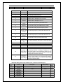
17
23
CHH100-2240-06
6
2700
261
2240
7700×2700×1500
1000
900
24
CHH100-2500-06
6
3000
281
2500
7700×2700×1500
1000
900
25
CHH100-2800-06
6
3300
324
2800
7700×2700×1500
1000
900
26
CHH100-3150-06
6
3700
363
3150
7700×2700×1500
1000
900
27
CHH100-3550-06
6
4500
428
3550
7700×2700×1500
1000
900
28
CHH100-4000-06
6
5000
482
4000
7700×2700×1500
1000
900
29
CHH100-4500-06
6
5600
542
4500
30
CHH100-5000-06
6
6200
595
5000
Outline dimension of frequency
Size of bypass
Size of bypass
inverters
cabinet
cabinet
W2×H×D(mm)
W1(mm)
W2(mm)
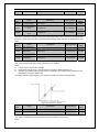
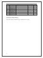
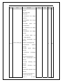
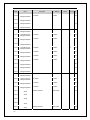
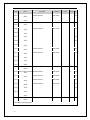
Table of the basic parameters of CHH100 Series of frequency inverters (10kV)
Rated
Rated
voltage
capacity
( kV )
( kVA )
CHH100-0220-10
10
2
CHH100-0250-10
3
Rated current
Motor power
(A)
( kW )
295
17
220
5200×2700×1200
1000
900
10
330
19
250
5200×2700×1200
1000
900
CHH100-0280-10
10
360
21
280
5200×2700×1200
1000
900
4
CHH100-0315-10
10
400
24
315
5200×2700×1200
1000
900
5
CHH100-0355-10
10
450
27
355
5200×2700×1200
1000
900
6
CHH100-0400-10
10
500
30
400
5200×2700×1200
1000
900
7
CHH100-0450-10
10
570
33
450
5200×2700×1200
1000
900
8
CHH100-0500-10
10
630
37
500
5500×2700×1200
1000
900
9
CHH100-0560-10
10
710
41
560
5500×2700×1200
1000
900
10
CHH100-0630-10
10
800
46
630
5500×2700×1200
1000
900
11
CHH100-0710-10
10
870
51
710
5500×2700×1200
1000
900
12
CHH100-0800-10
10
980
57
800
5500×2700×1200
1000
900
13
CHH100-0900-10
10
1100
64
900
5500×2700×1200
1000
900
Serial
Frequency inverter
NO.
model
1
18
14
CHH100-1000-10
10
1200
71
1000
5500×2700×1200
1000
900
15
CHH100-1120-10
10
1370
79
1120
5500×2700×1200
1000
900
16
CHH100-1250-10
10
1500
88
1250
5500×2700×1200
1000
900
17
CHH100-1400-10
10
1700
98
1400
5500×2700×1200
1000
900
18
CHH100-1600-10
10
1900
112
1600
6500×2700×1500
1000
900
19
CHH100-1800-10
10
2200
127
1800
6500×2700×1500
1000
900
20
CHH100-2000-10
10
2400
141
2000
6500×2700×1500
1000
900
21
CHH100-2240-10
10
2700
157
2240
6500×2700×1500
1000
900
22
CHH100-2500-10
10
3000
175
2500
6500×2700×1500
1000
900
23
CHH100-2800-10
10
3600
205
2800
6500×2700×1500
1000
900
24
CHH100-3150-10
10
4000
230
3150
6500×2700×1500
1000
900
25
CHH100-3550-10
10
4500
260
3550
6500×2700×1500
1000
900
26
CHH100-4000-10
10
5000
290
4000
11700×2700×1500
1000
900
27
CHH100-4500-10
10
5600
326
4500
11700×2700×1500
1000
900
28
CHH100-5000-10
10
6300
362
5000
11700×2700×1500
1000
900
29
CHH100-5600-10
10
7000
405
5600
11700×2700×1500
1000
900
30
CHH100-6300-10
10
8000
456
6300
11700×2700×1500
1000
900
31
CHH100-7100-10
10
9000
512
7100
11700×2700×1500
1000
900
『Remarks』: The outline dimensions of the high voltage variable frequency speed control systems listed in the table above are the standard sizes. The outline dimensions of the high voltage
variable frequency speed control systems may differ to the outline dimension of the high voltage variable frequency speed control systems listed in the table due to the requirements of the
actual users.
19
Chapter 3 System transportation, storage and
waste disposal
The functional unit electrical cabinets of CHH Series high voltage variable frequency speed control systems are
assembled, tested and packaged as a whole for outgoing from factories. During the transportation, the cabinet
bodies must be transported as a whole. To improve the reliability of the variable frequency speed control system,
and avoid the high voltage variable frequency speed control system being damaged during the transportation, this
chapter identifies the basic requirements for transportation and storage. The environmental requirements of
transportation and storage specified in detail in this chapter must all be strictly abided by. Any violation of the
relevant requirement in this chapter will influence the service life of the high voltage variable frequency speed
control system.
3.1 The transportation of high voltage variable frequency speed
control systems
The outer packaging of CHH Series high voltage variable frequency speed control systems can endure the external
impact from the sea, land or air transportation, but appropriate protection measures must be taken to avoid the
pollution of water immersing and dust. Also, during the process of sea, air and land transportation, the impact of
damage caused by mechanical external shocks and rough handling must be avoided. To realize correct shipping,
disassembling and storage, please note that all relevant precautions and indication and instruction tags are marked
on the packing boxes. We recommend entrusting logistic companies with a good reputation and credit with the
lifting and transportation of high voltage variable frequency speed control systems.
Transportation: CHH Series high voltage variable frequency speed control systems can be transported using cars,
trains, airplanes, ships and any other vehicles. During the transportation, the products must be handled with care.
Exposure to rain and sunlight are both strictly forbidden, no severe vibration, impact and upend is allowed.
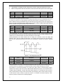
Hoisting: The power unit cabinets, control cabinets and switch cabinets can all be handled via flying rings. Due to
the large weight of trans-phase transformers, while hoisting, it is required to disassemble the 2 shoulders of the
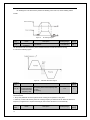
cabinet tops and then complete the hoisting via the flying rings of trans-phase transformers.
Method 1
方式二
Method 2
拉
Pull
Push
推
滚杠 bars
Roll
地平面
Ground
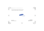
Figure 8 Hoisting schematic drawing of high voltage frequency inverters
During the handling of variable frequency speed control systems, it is allowed to do the job referring to the 2
methods shown in the figures above. Method 1 is to put the fixed wire ropes through the drill holes on the bottom
of the frequency inverter cabinets; the latter method is to carry out the handling using rolling bars.
3.2 Arrival acceptance check
After receiving the high voltage variable frequency speed control equipment that you ordered, if there is anything
wrong with the products you ordered or they don’t comply with the specifications that you ordered, please contact
the agent from whom you order the equipment or contact the nearest office of our company.
① Check the data tags of the high voltage variable frequency speed control systems and confirm the models
and specifications of the equipment you ordered.
② Check whether any damage has occurred during the handling and transportation on the appearance, such as
20
damage to the cabinet body appearance, any deformation to the door and sideboards and any falling off of
the inner devices, etc.
③ Open the cabinet door and check the situation inside the cabinet, and check for the occurrence of the
loosening of the control cables, water immersion, as well as missing or damaged devices.
④ Contrasting to the supply lists, check if there’s any shortage and other issues of the equipment that you
ordered, to prevent the omission of parts.
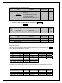
『Note』Since the configuration requirements of the users to the high voltage variable frequency speed control
systems are different, the configurations of the high voltage variable frequency speed control systems of same
capabilities will also differ.
3.3 Storage and conditions
Inappropriate methods of custody of power electronic equipment will affect the service lives of the equipment, or
even result in the failure of the equipment.
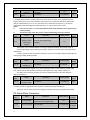
Table – Custody environment conditions
Items
Storage temperature
Relative humidity
Specifications
-40~+70℃, the change of air temperature of less
than 1℃/Min
5 ~95%
Don’t put in the places where
condensation and freezing occurs
due to acute changes of
temperature.
Not subject to direct sunlight, dust, corrosive gas, flammable gas, oil mist, vapor or
water dripping.
Preservation
environment
General requirements:
① Don’t place it directly on the ground; place it on appropriate supporting objects.
② If there is any impact of humidity, appropriate desiccating agent shall be provided: each unit of desiccating
agent (30g) absorbs 6g of water content. According to the packaging materials used, you will need the
desiccating agent of the following amounts: Polyethylene metal film: 10 units per square meter; aluminum
metal film: 8 units per square meter.
③ Using polyethylene materials or aluminum metal film as the protective packaging can prevent the water
content from infiltrating:
Regular inspections: During the whole storage period, the inspection of the storage status and packaging
status of the equipment shall be carried out once a month. Focus, in particular, on mechanical damage and
the damage caused by humidity, temperature or fire hazard. If the packaging is damaged or you have found
that the equipment has been damaged, you should immediately check the equipment damage situation, and
store the variable frequency speed control system according to the requirements mentioned above after
repairing the damaged equipment.
3.4 Storage of spare parts
After receiving CHH Series high voltage variable frequency speed control systems, you shall immediately check
whether there is any damage to the spare parts, and if any damage to the spare parts is found, please report it to our
company. Our company will not undertake any product quality guarantee responsibility for the damages caused by
external shocks or external environment within the product quality guarantee period. Within the quality guarantee
period, to keep the equipment spare parts from being damaged, please pay attention to the following items: there
must be no vibration or impact at the storage place, and it is a requirement to prevent damage from moisture, frost,
temperature, dust and gravels. The environmental conditions shall meet the requirements of temperature and
humidity: The spare parts must be stored in a dry original packing box with no flying insects, and kept away from
corrosive gas. The relative air humidity shall be 5%~95%, and the storage temperature of the spare parts shall be
-5℃~+55℃. The circuit boards must be stored in anti-static packing bags with no leakage of moisture-proof agent,
and must be kept away from corrosive gases that will cause damage to the circuit boards or gases containing
alkali-saline or other impurities and mustn’t be frozen. If you find that the humidity has surpassed the maximum
allowable extent in the air, environmental protection measures such as cooling, heating, dehumidifying and other
methods shall be taken to guarantee the environmental conditions for storing the spare parts.
The power unit is equipped with electrolytic capacitors on the inside, the long-term power-off of the electrolytic
capacitors will lead to the deterioration of their electrical characteristics; therefore, the preservation shall be carried
out in the method of electrifying once every year.
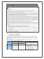
3.5 Product waste treatment
Notes
When the product packs and the products are being discarded, they shall be treated as industrial waste,
otherwise injury accidents or environmental pollution may occur.
The packaging of CHH Series high voltage variable frequency speed control systems shall be designed with the
minimum usage of the packing materials that have adverse effects on the environment; some of the packing
materials can be recycled and reused. The treatment of the packing materials shall comply with the national
standard related to environmental protection.
While discarding the devices inside the high voltage variable frequency speed control systems, the electrolytic
capacitors, PCBs, electronic components and other parts need to be treated with correct methods for any part of
them not to cause harm to the surroundings. These treatment methods can refer to the national legislation and
regulations to the environment protection.
21
Chapter 4 System Installation and Wiring
The main bodies of CHH Series high voltage variable frequency speed control systems are composed of the
trans-phase transformers, unit switch cabinets, main control cabinets and others. Wiring cabinets or bypass witch
cabinets are also included according to the user’s choice, therefore, as for different projects, the arrangement and
layout of the equipment shall be determined according to the appropriate positions, with the layout and installation
diagrams provided.
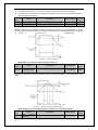
4.1 Installation of cabinet bodies
1.
Requirement of running environment
The efficiency of CHH Series high voltage variable frequency speed control systems is over 96%, 4% of the loss
will be basically converted into heat energy. Therefore, the cooling issue of the high voltage variable frequency
speed control systems needs to be taken into consideration. If the installation environment of the high voltage
variable frequency speed control systems is narrow and the ambient temperature is high, additional installation of
forced-air cooling unit or air conditioning cooling devices is needed. We recommend adopting the exhaust air
rate of larger than 1M3/S every 200KW of capacity during air cooling; and when air conditioning cooling is used,
more than 4 HP of air conditioners shall be configured for every 200KW of capacity.
2.
Requirements of spacing for cabinet placement
500
For the drawings of the cabinet dimension, outline dimension and the bottom plate installation of the variable
frequency speed control system, please refer to the drawings related to engineering technical information. All
cabinet bodies shall be installed according to the drawings and sufficient spacing shall be provided in the periphery,
in order to guarantee the air flow, the maximum door swinging and the space required for maintenance, and also
providing the channel for entering the installation basis (aisle spacing, etc.) and ensuring the space for the auxiliary
equipment used for providing the transportation of the variable frequency speed control system.
障碍物
Barrier
800
800
Optional parts
选
配
部
分
Figure 9 Schematic Drawing 1 of installation requirements of the high voltage frequency inverter (Front view)
22
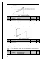
500
800
800
Interior ground plane
10# Steel channel
20# Concrete
800
900
Figure 10 Schematic drawing 2 of the installation requirements of high voltage frequency inverters (Side view)
The basic requirements of the widths of the surrounding channels of the cabinet are shown in the figure above
and the table below.
Minimum widths of the surrounding channels of high voltage variable frequency speed control systems
Layout mode
Maintenance channel
Running channel
Dual-row layout
1m
2.0m
Single-row layout
1m
1.5m
The cooling air duct of the variable frequency speed control system is shown in the figure below. To guarantee
sufficient cooling, it must be guaranteed that the distance between the top of the variable frequency speed control
system and the roof complies with the requirement of the relevant national regulations. For further lowering
ambient temperature, users can install centralized ventilation air ducts for transmitting the hot air through
centrifugal blower and directly lead it to the outside through the air ducts.
Centrifugal air blower
Filter mesh Air outlet
Centrifugal air blower
Air outlet Air outlet
Air outlet
Power unit
Power unit
Power unit
Air inlet
Air inlet
Air duct
Figure 11 Schematic drawing of the cooling air ducts of the high voltage frequency inverter
3.
The requirement of the foundation installation of the variable frequency speed
control system
The cabinet bodies of CHH Series high voltage variable frequency speed control systems must be vertically
23
installed onto the concrete casting foundation framework made of flat steel channels, the overall roughness of the
surface shall be less than 5mm. the foundation must be made of non-combustible materials, and have smooth and
abrasion-free surface, and shall be moisture-proof and able to bear the weight of the variable frequency speed
control system. The cable ducts must be made of non-combustible material and have smooth and abrasion-free
surface, and shall be moisture-proof and dust-proof, providing the measures for preventing the animals from
entering.
High voltage variable frequency speed
control system cabinet
Power unit
Power unit
Power unit
Figure 12 Schematic drawing of the basic requirements of installation of the high voltage frequency inverter
Installation of cabinet bodies
The high voltage variable frequency speed control system is composed of more than 3 cabinet bodies (this depends
on the power size and the layout mode). According to the requirement, a single cabinet or multiple cabinets can be
placed upon the foundation steel channels vertically using traveling crane or forklift. The trans-phase transformer
cabinet must be installed separately.
The cabinet bodies shall be assembled, connected, positioned and aligned, then shall be directly welded onto
foundation steel channels, the connecting wires inside the cabinets and the ones between the cabinets shall be
installed under the guidance of the professional from our company.
In some cases, the trans-phase transformers and power units shall be separately packaged for transportation, and
shall be installed into the trans-phase transformer cabinets and power unit cabinets under the guidance of the
professional from our company after arriving at the destination.
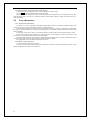
4.
Notes
It shall be installed onto the non-combustible structure made of basic steel channels, otherwise it
may cause fire.
Ensure that various kinds of fibers, paper scraps, sawdust, metal fragments and other foreign
matters don’t enter into the cabinet or adhere to the radiators; otherwise it may cause accidents or
fire.
The following installation guide is applicable to the general installations in industrial environment. If the
application in special environment and occasions is required, please make inquiry to our company for detailed
installation procedures.
1.
Before the machinery installation, please be sure to meet all environmental conditions described in the
previous points.
2.
Examine the basic level with level instruments. The allowable maximum overall roughness is less than 5mm.
If the ground surface is not flat, then it must be smoothed.
3.
Move to the installation position. Please refer to the requirement of Chapter 3, Handling of high voltage
variable frequency speed control systems to do the handling and moving.
4.
Open all cabinet doors, and carefully inspect possible transportation damage of the variable frequency speed
control system and the attached equipment thereof. If any part is damaged or missing, please immediately
contact the technical service department of our company and the corresponding transportation company.
Please note the opening methods of cabinet doors.
5.
Check whether the cabinet door can be fully opened or closed; if not, the cabinet body needs to be adjusted.
Examine the position-restraint locks on the doors: after the power is turned on, aside from the doors of the
main control cabinets, no other front doors and back doors can be opened. The illegal opening of cabinet
doors will trigger the alarm.
6.
Perform the fine adjustment of the cabinet bodies, and fix the adjacent cabinet bodies tightly with binding
bolts.
7.
Under the guidance of the professionals of our company, connect the wiring inside the cabinet bodies, install
and fix the power units.
Note: Please pay attention to the methods for opening the cabinet door; forced opening of cabinet door is forbidden,
otherwise the equipment will be damaged.
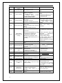
Table of basic installation check items of plate cabinet
Working
Inspection items
Quality standard
Inspection methods and
procedure
apparatus
Basic
Basic steel non-straightness
<1 mm/m
Guy wire inspection
installation Error levelness
(or <5 mm/full length)
Track level bar inspection
Basic centerline error
±5mm
Inspect with ruler
Plate cabinet basis and ground fixing ≤10mm
Inspect with leveler or
mode
communication pipes
Consistent
to
the
Inspect with leveler or
Elevation difference
ground elevation
communication pipes
with contrast to the
Basic layout
According to the design Inspect
drawings
Number of basic steel grounding points
>2 points
Inspect by observation
24
Grounding connection
Firm, with good
conduction
Inspect by wrenching and
guiding
4.2 Installation of the high voltage parts
1.
Standard requirement of high voltage distributions
Firstly, the high voltage power supply needs to pass through the main circuit breaker and then shall be
connected to CHH Series high voltage variable frequency speed control systems; it is allowed to close the
main circuit breaker only after receiving the high voltage closing permit signal.
The high voltage power supply of the main circuit breaker shall be directly connected into the input terminal
of the switch cabinets (or incoming cabinets) of the variable frequency speed control system without the need
of passing through the input reactor.
The variable frequency output of high voltage variable frequency speed control systems is directly connected
to high voltage motors via the output terminals of the switch cabinets (or incoming cabinets).
Notes
2.
The input and output terminals cannot be connected incorrectly, otherwise the high voltage variable
frequency speed control systems will be damaged.
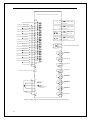
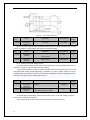
Wiring of the switch cabinets of high voltage variable frequency speed control systems
Terminal ID
Input
L1
L2
L3
Output
U
V
W
Terminal name
Main circuit power supply input, 1st
phase sequence
Main circuit power supply input, 2nd
phase sequence
Main circuit power supply input, 3rd
phase sequence
High voltage frequency inverter output,
1st phase sequence
High voltage frequency inverter output,
2nd phase sequence
High voltage frequency inverter output,
3rd phase sequence
Remarks
Connect to 3-phase high voltage AC power
supply, 1st phase sequence
Connect to 3-phase high voltage AC power
supply, 2nd phase sequence
Connect to 3-phase high voltage AC power
supply, 3rd phase sequence
Connect to 3-phase AC high voltage motor, 1st
phase sequence
Connect to 3-phase AC high voltage motor, 2nd
phase sequence
Connect to 3-phase AC high voltage motor, 3rd
phase sequence
【Remarks】The phase sequence of U, V and W output of the high voltage variable frequency speed control
systems may be inconsistent with the phase sequence of power supply L1, L2 and L3; on the occasions when
the power frequency power supply bypass is needed, please check the I/O phase sequences of the high voltage
variable frequency speed control systems, and make the phase sequence of both consistent, otherwise the system
may not work normally.
3.
Requirements of equipment and cables
Main circuit breaker
The main circuit breaker may be the vacuum or gas insulation circuit breaker. It must not only meet the
requirement of the supply voltage and current, but also the requirement of the rated voltage and current of the
trans-phase transformer on the primary side. Its basic electrical characteristic also has to be able to bear the
closing impulse current of the transformer and the failure current caused by the secondary side short circuit
of the transformer within 100ms, and won’t cause trip.
Protective equipment
The high voltage switch on the power side of CHH Series high voltage variable frequency speed control
systems shall be configured with reasonable protection, the setting of the protection definite value shall be
carried out in reference to the following principles:
When the winding on the primary side or the incoming cables on the primary side of the trans-phase
transformer fails, the switch must conduct immediate trip. The setting value of the protection current must be
sure to dodge the excitation surge current for switching-in no-load without trip (this can be set as 8 to 10
times of the rated current of the trans-phase transformer).
The fault protection of the secondary side of trans-phase transformers adopts the method of delayed trip.
When short circuit failure occurs to the winding on the secondary side of the trans-phase transformer, the
cables connecting the secondary side of the trans-phase transformer with system units, and the unit input
bridge rectifier, the incoming switch can be flipped open. With short delay of protection, the time settings can
be adjusted and can be set to ensure the trans-phase transformer of no trip will occur during the period of
excitation surge current. The movement current setting value can be set as twice the rated current of the
rectifying transformer, so as to ensure that when failure occurs on the secondary side of the rectifying
transformer, trip will be performed within 500ms.
Overload protection (optional) is a long-time overload protection with the feature of inverse time limit, and
can protect the long-time overload of transformers and cables.
If the system is a part of a high-voltage large-capacity motor reconstruction project, the vertical protection of
the high voltage motor protection shall quit during the variable frequency operation, and shall be put in
during the power frequency bypass, the switching function needs to be realized in the technical schemes.
Primary side cables of transformers
25
No special requirement to the cables between the primary side of the transformer and the circuit breaker is
proposed. The rated voltage shall be consistent with the circuit voltage on the primary side. The rated current
of cables shall comply with the protection setting value of the transformer. The lower capacitance value shall
be designed according to the maximum expected ambient temperature, cooling factors and the other factors
required by local electrical regulations, and the installation shall be completed according to the standard for
medium-voltage devices.
Cables with outputs to the motors
No special requirement of the Cables from CHH Series high voltage variable frequency speed control
systems to the motors is proposed. We recommend the length to be no longer than 1000 meters, the case that
the field cable length is larger than 1 kilometer shall be proposed in the order.
The rated voltage of the cables is consistent with the corresponding motor models; the rated current of the
cables shall comply with the motor models and the permit overload current for motor protection. The
capacitance lowering of cables shall refer to the highest ambient temperature, cooling factors and the other
factors required by local electrical regulations. The installation shall be completed according to the standard
for high-voltage devices.
Since the waveforms of the output voltage and current of CHH Series high voltage variable frequency speed
control systems are close to standard sine waves, no special shielding is required for the cables. Therefore
there is no need to take special measures for the common mode current.
4.
High voltage cabling
The cabling of main power supply and the motor must comply with national standards, please refer to the
specifications and recommendation of the cable manufacturers.
We recommend using separately shielded armored 3-phase cables; if single-phase cables are used,
the combination of 3-phase cables is required to ensure the EMC characteristics.
If the area of the shielding layer of the cables is less than 50% of the area of a 1-phase cross section,
then an additional grounding line must be provided to prevent the shielding layer of the cables from
overheating.
The cable terminations must comply with the requirement of the cable manufacturers, the cables
connectors must be installed at the terminations.
The grounding of the grounding terminals of the corresponding cables must comply with the national
standard of electrical installation.
5.
Equipment grounding
6.
Precautions
All connections of the electrical installations of high voltage variable frequency speed control systems
Users shall be sure to provide good grounding wires with grounding resistance of less than 4 ohms, copper
bars shall be used for connecting the cabinet bodies of CHH Series high voltage variable frequency speed
control systems, the connecting wires between the grounding points of whole sets of devices and the
grounding points of grids shall use the copper-core cables with the cross-section of no less than 50 mm2. The
detection of grounding system is required before being put into operation, in order to guarantee the
equipment and personal safety.
must be installed by experienced electric engineers according to the national standards related to
electrical installations.
All high-voltage connectors must receive insulation treatment to ensure good insulation.
The high voltage connecting positions must be kept clean and meet the requirement of the
corresponding cleanliness.
All work must be carried out while the main power supply and the auxiliary power supplies are all
disconnected.
Connect the main incoming cables and the output motor cables correctly, otherwise the equipment of
the whole variable frequency speed control system will be seriously damaged when the power is
turned on.
The phase sequence of output cables is related to the rotating direction of the motor, please connect
the U, V and W according to the requirement of load turning directions, and perform tests before
formally putting into operation.
1. Before cabling, please confirm that the input power supply has been cut off.
There is the risk of electric shock and fire.
Danger
2. Please call electric engineering professionals to perform the cabling operation.
There is the risk of electric shock and fire.
3. Please be sure to make reliable grounding of the cabinet bodies. There is the risk
of electric shock and fire.
4. Please be sure to test the normal functioning of the power/variable frequency
switch and the emergency breaking buttons before power is turned on. There is
risk of injuries. (Users shall take the responsibility of cabling)
5. Please don’t touch the output terminals directly, the output terminals of the
variable frequency speed control system must not be connected to the casing,
there mustn’t be short connections between output terminals. There is the risk of
electric shock and causing short circuit.
Danger
26
1. Please check whether the AC main circuit power supply is consistent with the
rated voltage of the variable frequency speed control system, otherwise there will
be risks of injury and fire hazard.
2. The voltage resistance test shall be performed according the manual; otherwise it
will cause the damage to the semi-conductor components and others.
3. Please use the screw driver of designated torque to tighten the terminals,
otherwise there will be the risk of fire.
4. Please don’t connect the input power supply line to the output U, V and W
terminals. Putting voltage on the output terminals will cause the inner damage of the
variable frequency speed control system.
Notes
All high voltage connectors must receive insulation treatment to ensure good insulation. The high voltage
connecting positions must be kept clean and meet the requirement of the corresponding cleanliness.
The electrical insulation distance of the high voltage positions must comply with the requirement of electrical safe
distance to avoid any short circuit caused by the electric discharge.
The electric insulation detection test to the input end of the system shall be performed after the short-connecting
and grounding of the iron core of the trans-phase transformer and all secondary outgoings; while performing the
electric insulation detection test to the output end of the system, no unit output is allowed to be connected
into the output cables; otherwise the power units will be damaged.
After the completion of all connections, the detection of electric insulation properties shall be carried out to the
input end of the system, the experimental voltage shall use the reference value as follows: for 6kV system, it shall
be 25kV, for 10kV system, it shall be 35kV. During the field hand-over test, the actual insulation test voltage shall
choose 75% of the value mentioned above. If the air humidity is apparently too large on the spot, or there’s the
situation that the humidity is relatively large for a long time in the long-term storage environment before the
installation, commissioning and operation of the system, if the equipment are found to be damped before putting
into operation, then further voltage withstand test must not be carried out, in order to avoid the equipment being
damaged. The voltage withstand test shall be performed after using non-fire heating source for drying.
The indicators at the high voltage positions must be clear and eye-catching to avoid errors.
Installation of large-current positions: to enable the variable frequency speed control system to meet the technical
properties, great attention must be paid to the installation of large-current positions (All incoming terminals and
output terminals with the current flow of larger than 10A shall be considered large current terminals). The key
points are:
◆ Terminals shall be made of the materials with excellent conductive properties, such as oxygen-free copper
terminals, silver-plating or tin-plating fasteners and other connecting materials.
◆ All terminals shall be carefully cleaned with ethanol before connecting.
◆Connections of all connectors shall be very reliable, the fasteners shall be tightened with wrenches, the
important connectors shall be wrenched tight reliably with torque wrenches to ensure the contact resistance is
less than 2 milliohms.
◆ The fasteners of all large-current connecting positions shall include spring rings, which shall be pressed flat
after fastening.
◆ The large-current connecting wires shall use appropriate current density to avoid the heating and the
consequent impact on equipment use.
4.3 Wiring of user terminals
1. General introduction of user terminals
CHH Series high voltage variable frequency speed control systems provide the terminals of 16 channels of digital
inputs, 8 channels of relay outputs, 3 channels of analog inputs, 4 channels of analog outputs, 1 channel of
high-pulse input and 1 channel of high-pulse output. All user terminals are programmable and can be specified
using the function codes.
CHH Series high voltage variable frequency speed control systems connect all terminals the users used onto the
terminal blocks. Please carry out the wiring from the terminal blocks while using.
1) Description of the terminal ports the users used
Classification
Terminal markings
Terminal functions
Technical specifications
485 communication
485+
Standard 485 Physical interface, supporting
Upper
positive pole
standard MODBUS communication
communication
485 communication
protocols
485-
negative pole
1. Forming the optical coupler isolation
S1、S2、S3、S4、
input with COM
S5、S6、S7、S8、
2. The input voltage can only be the 24V
Digital input
provided by the system
S9、S10、S11、S12、 Switch input terminals
S13、S14、S15、
3. The suspension of terminals will be
S16
regarded as disconnected
4. Input impedance: 3.3KΩ
27
1.
HDI
High pulse input
terminals
2.
3.
4.
24V Power
supply
+24V
COM
10V Power
supply
+10V
GND
24V power supply
provided by the system,
for the use of digital
input and high-pulse
input.
24V Powers supply
grounding
+10V power supply
provided by the system,
for the use of analog
input
+10V Powers supply
grounding
1.Maximum output current 150mA
1. Maximum output capability 20mA
1.
2.
AI1、AI2
Analog input terminals.
Support the inputs of
voltage and current.
Analog input
3.
4.
AI3
AO1、AO2
Analog input terminals.
Only support voltage
input, the input range
permits negative
voltage
Analog output
terminals, Only support
voltage output
1.
2.
3.
4.
1.
2.
3.
1.
Analog output
AO3、AO4
Analog output
terminals, Support the
inputs of voltage and
current.
2.
3.
1.
Relay output
R01、R02、R03、
R04、R05、R06、
R07、R08
2) Wiring diagram of user terminals
28
Forming the optical coupler isolation
input with COM
The input voltage can only be the 24V
provided by the system
The suspension of terminals will be
regarded as disconnected
Input impedance: 1.1KΩ
Relay output terminals
2.
Forming a loop connection with GND
We recommend using the +10V
provided by the frequency inverter as
the input voltage.
For voltage input, voltage range
0~+10V; for current input, current
range 0~20mA, 20mA current
responds to +5V.
Input impedance: 20KΩ (voltage)
/250Ω (current).
Forming a loop connection with GND
We recommend using the +10V
provided by the frequency inverter as
the input voltage.
Voltage input range is -10V~+10V.
Impedance of voltage input is 20KΩ.
Outputting the voltage corresponding
to the GND terminals.
Output voltage range 0~+10V
Maximum output loop current range
0~2mA, minimum input impedance of
external circuit 5KΩ.
Outputting the voltage and current
corresponding to the GND terminals.
While voltage output: Output voltage
range 0~+10V, output permit
impedance≥5KΩ
While current output: Output current
range 0~20mA, output permit
impedance 100~500Ω
Contact point definition: A Public
terminal, B Normally closed, C
Normally open.
Contact point capacity: AC250V/1A,
DC30V/1A.
CHH Series variable frequency speed control system
+24V
AO1
High-speed impulse
input
高速脉冲输入
HDI
Multi-function input
terminals1
多功能输入端子1
S1
Multi-function input
terminals 2
多功能输入端子2
S2
GND
AO2
Multi-function input
terminals 3
多功能输入端子3
S3
Multi-function input
terminals 4
多功能输入端子4
S4
GND
J3
V
Multi-function input
terminals 5
多功能输入端子5
S5
Multi-function input
terminals 6
多功能输入端子6
S6
Multi-function input
terminals 7
多功能输入端子7
S7
Multi-function input
terminals 8
多功能输入端子8
S8
Multi-function input
terminals 9
多功能输入端子9
S9
AO3
I
J4
V
GND
AO4
I
GND
0~10V
Analog
模拟输出2output 2
0~10V
模拟输出3output 3
Analog
0~10V/0~20mA
Analog
模拟输出4output 4
0~10V/0~20mA
HDO
Multi-function input
terminals 10
多功能输入端子10
S10
Multi-function input
terminals 11
多功能输入端子11
S11
Multi-function input
terminals 12
多功能输入端子12
S12
Multi-function input
terminals 13
多功能输入端子13
S13
RO1C
Multi-function input
terminals 14
多功能输入端子14
S14
RO2A
Multi-function input
terminals 15
多功能输入端子15
S15
RO2B
Multi-function input
terminals 16
多功能输入端子16
模拟输出1output 1
Analog
COM
OC collector high-speed impulse output
开路集电极高速脉冲输出
RO1A
RO1B
Relay
output 1
继电器输出1
Relay
output 2
继电器输出2
RO2C
S16
RO3A
COM
PE
RO3B
Relay
output 3
继电器输出3
RO3C
RO4A
标准485通讯接口(
modbus
)
Standard 485 communication
interface
485+
485-
RO4B
Relay
output 4
继电器输出4
RO4C
RO5A
RO5B
Relay
output 5
继电器输出5
RO5C
RO6A
+10V
A
m
0
2
0
/
V
0
1
0
A
m
0
2
0
/
V
0
1
0
-10V~+10V
AI1
AI2
AI3
V
I
RO6B
J1
Relay
output 6
继电器输出6
RO6C
J2
V
I
电压电流输入
Voltage and current
转换跳线
Jumper Switch
RO7A
input
RO7B
Relay
output 7
继电器输出7
RO7C
GND
模拟输入
Analog input
PE
RO8A
RO8B
Relay
output 8
继电器输出8
RO8C
Figure 13 Wiring diagram of user terminals of the high voltage frequency inverter
29
2.
Precautions
Note the grounding check
Usually, the user control wires shall not use the wires with reinforced insulation. If wire insulators are
damaged due to certain reasons, then the intrusion of the high voltage into the control circuit is possible. This is not
permitted for European Low Voltage Directive. If this situation occurs, electric shock or equipment damage may
result.
If shielding cables are used, the cable shielding layer can only be grounding at a single termination of each
cable.
To ensure the normal work of the variable frequency speed control system, it must be guaranteed that work
of various signal lines is normal without being affected by various electromagnetic interference. Therefore,
during the installation of user control wires, the correct installation of these signal lines must be focused on in the
following aspects.
◆Separate wiring of the signal wires and power cord, especially the large-current high voltage wires, must
be ensured to avoid electromagnetic interference. The control cables shall not be wired parallel to the power
cables. If this situation is inevitable, the distance between the control cables and main cables must be kept as
a minimum 30cm. The control cables and power cables shall be cross-wired perpendicularly.
◆ Separate wiring of digital signal lines and analog signal lines is required to avoid mutual interference.
◆ If the signal lines and power cords must be wired in the same place, then the shielding measures shall be
taken to the signal lines, so as to reduce the interference produced by power cords to the signal lines as
much as possible.
◆ Avoid the parallel wiring of signal lines and power cords so as not to produce mutual interference.
◆ The grounding of signal lines must be connected to shielding wires reliably; the shielding layer must also
be reliably grounded at one single termination.
◆ If necessary, the signal lines can be connected to the external through the threading of metal conductive
casing pipes. In this way, various interference signals can be reliably isolated to ensure the normal operation
of the variable frequency speed control system.
◆ For reducing the interference and attenuation of the control signals, the connection length of the control
signal lines shall be limited within 50cm.
Note the wiring inspection
After the wiring is completed, please be sure to check
Whether there is anything wrong with the wiring.
Whether there is any residue of the screws and connectors inside the equipment.
Whether there is any loosening of the screws.
Whether the bare conductors of the terminal parts are connected to other terminals.
30
Chapter 5 System debugging and running
The debugging of CHH Series high voltage variable frequency speed control systems must be carried out under the
guidance of the professionals of our company. The function testing, debugging and parameter settings must be
carried out strictly according to the relevant regulations and the instruction manual of the high voltage frequency
inverter of our company.
During debugging, users must provide at least 2 professional electric technicians as the running staff required by
the debugging, and the running staff must comply with the following conditions:
• Familiar with the high voltage electrical equipment and the corresponding safety standards.
• Familiar with the Users’ load driving process.
• Authorized to operate high voltage equipment (Power circuit breakers and other high voltage transmission
switches, etc.).
• Authorized to operate transmission equipment.
Note
5.1
Ensure the high voltage variable frequency speed control systems are correctly wired, and all
electrical cabinet doors are closed before connecting to the power supply. The cabinet doors cannot
be opened after the power is turned on.
Correctly setting the function parameters of the high voltage variable frequency speed control system.
While booting, the system is designed to ensure personal and equipment safety.
When the power of the variable frequency speed control system is turned on, even if it is in the state
of shutdown, the terminals are still electrified and must not be touched.
The running and stopping of the high voltage variable frequency speed control systems can not be
operated by the methods of connecting or disconnecting the main circuit.
Items of detection and confirmation before debug running
1. Appearance: The coating layer on the surface shall be uniform with no bubble or falling off, and there shall
be no trace of scratching or flash, the assembly of the whole machine shall be tight with no existence of
undesirable phenomenon.
2. Silk print: The silk printing on the chassis casing is correct, the characters and symbols are clear and correct,
with no burrs, segment missing or other undesirable phenomenon in the fonts, and the appearance shall be clean
and bright.
3. Functional short wiring: complies with the process files, the J4 of control panel shall adopt the method of
short connection of 485 pins.
4. Whether there are any miscellaneous objects inside the chassis, and whether the machine numbers on the
data tags on the chassis are consistent with the machine numbers in Product File.
5. The shielding layer of the I/O shielding wires on the voltage detection board coming out from the power
unit cabinets near the main control cabinets shall be grounded on one termination; the I/O shielding wires on the
speed tracking board shall be grounded on one termination.
6. Check whether the connection wires between the trans-phase transformer and power units are firm and
whether the connection wire sequence is consistent.
7. The optical fiber jump wires between the optical fiber drive board on the control panel and the power units
are correctly connected.
8. Whether the line sequence of all control lines are consistent with the diagrams.
5.2
Tests of Control cabinet power on and after power-on
5.2.1 Main control cabinet power on
1. Ensure that L1, L2 and L3 are disconnected to high voltage inputs.
2. Start the UPS; when the keyboard on the running panel of the frequency inverter displays “-CHH-” and is
flashing, the 7 LED lights shall all be turned on. After 2 seconds, all LED lights shall go out except the ones that
correspond to Hz.
3. The interface of the touch screen shall display the initialization interface, and finally pop up the Login
button. After pressing the login button of the person in charge, the system will enter the main interface and prompt
that the DC bus lacks voltage.
4. Observe deviation of the temperature displayed on the trans-phase transformer cabinet and the actual
ambient temperature, and if it is less than 1℃, it will indicate that the deviation is normal.
5.2.2 Testing whether the work of KM1 (QS1), KM2 (QS2) and KM3 are normal
1. Ensure that L1, L2 and L3 are disconnected from the high voltage power supply
31
2. In the touch screen interface----》Function Settings, click the Settings button within the Running Mode box
on the interface of Function Settings; Enter the Power/Variable Frequency Switch interface.
3. Click Variable Frequency in the interface
4. You will then hear the sound of the contactor twice, and the 2 indicator lights on the leftmost of the switch
cabinet will be turned on.
5. Measure the on-off of KM1, KM2 and KM3 with a multimeter, now KM1and KM2 are on, and KM3 is off.
6. Click “Cut off high voltage” in the interface.
7. You will then hear one beep of the contactor, the indicator light of switch cabinet will go out.
8. Measure the on-off of KM1, KM2, KM3 with a multimeter, now KM1, KM2 and KM3 are all off.
9. Click “Power frequency” in the interface.
10. You will then hear one beep of the contactor, the indicator lights on the leftmost of the switch cabinet are
turned on
11. Measure the on-off of KM1, KM2 and KM3 with a multimeter, now KM1and KM2 are off, and KM3 is
on.
12. UPS power-down, reboot the UPS after the system is all power down.
13. Reboot the UPS, then, after switching the power on, you will hear a beep of the contactor sound, the
indicator lights of the switch cabinet will go out.
14. Click “Variable frequency” in the interface, and wait until the 2 indicator lights on the leftmost of the
switch cabinet are both turned on.
15. Press the emergency breaking switch on the control cabinet, and you will hear one beep of the contactor.
16. Measure the on-off of KM1, KM2 and KM3 with a multimeter, now KM1and KM2 are off, and KM3 is
on.
17. Turn the emergency breaking knob to the normal position.
18. Measure the on-off of KM1, KM2 and KM3 with a multimeter, now KM1and KM2 are on, and KM3 is
off.
5.2.3 Testing whether the power alarm is normal
1. Main control cabinet is power on, turn the switch of the input power supply 1(Q1) open, the system will
trigger the alarm of Power supply 1.
2. Close the switch of the input power supply 1 (Q1), the system alarm disappears.
3. Open the switch of the input power supply 2 (Q2), the system will trigger the alarm of Power supply 2.
4. Close the switch of the input power supply 2 (Q2), the system alarm disappears.
5. Close the UPS, the system will trigger the alarm of UPS.
6. Boot the UPS, the system alarm disappears.
5.2.4 Test insulation resistance
1. Short connect L1, L2, L3, U, V and W.
2. Main control cabinet is power on, switch the system to the Power frequency work state via the touch
screen.
3. Measure the inner resistance between the short-connected L1, L2, L3, U, V, W and the cabinet body; the
resistance shall be over 20MΩ.
4. Measure the insulation resistance between each power unit casing and the cabinet body with a withstanding
voltage tester; the resistance shall be over 20MΩ.
5.2.5 Motor parameter settings
1. Complete the parameter settings of the function codes of P2.00~P2.05 according to the data plate of the
motor.
5.3
Main loop power on and power-on debugging
5.3.1 Whole machine high-voltage on
1. Connect L1, L2 and L3 separately to the high voltage inputs. Make sure the U, V and W are disconnected
to the motor; and the system is in the state of power-off. Close all cabinet doors.
2. Switch the system to Variable frequency state via the touch screen.
3. Connect to the high voltage according to the operation procedures (when it is the first time to connect to
high voltage power supply, all staff need to stay over 3 meters away from the cabinet).
4. After over 6 seconds after power is turned on, the Ready LED (Yellow LED) is turned on.
5. Make sure that the noise of the trans-phase transformer cabinet is below 75db.
5.3.2 Correction of the unit voltage and temperature
1. Make sure that L1, L2, L3 are separately connected to the high voltage inputs. Make sure U, V and W are
disconnected to the motor, and the variable frequency speed control system is working in the state of variable
frequency.
2. Log in the touch screen as the person in charge, and enter the parameters in PD group.
3. Observe PD.03~PD.29, the temperature deviation displayed shall be no more than 2℃.
4. Observe PD.30~PD.56, the voltage deviation of the unit shall be no more than 50V.
32
5.3.3 Disconnecting the motor and no-load running
1. Keep the power-on configuration of 3.2, and connecting to a high voltage.
2. Press “RUN” button on the keyboard, and run at 50HZ.
3. The blower on the cabinet top starts to work, listen and check whether there’s any abnormal sound or noise
when the blower starts; if no noise or abnormal sound is heard and the running is steady, then the air blower is
working normally.
5.4
Test with motors
5.4.1 No-load test with motors
1. Connect L1, L2 and L3 separately to the high voltage inputs; connect U, V and W to the high voltage motor.
Connect to the input, switch the frequency inverter to variable frequency.
2. Set the output frequency to 10Hz while testing with the motor, then increase the frequency to 20Hz after
the motor is running steadily, then increase to the rated frequency of the motor with this method and start the motor,
and run at 50HZ.
3. During the whole process, there is no abnormal sound or vibration of the motor, and the running is steady.
4. Press the Slowdown & Stop button, the output frequency of the frequency inverter has decreased. And
press the Free stop command when it decreases to about 5HZ.
5. After blocking the pulse, press the Start command again, then the frequency inverter will reach the current
rotating speed within 2 seconds, and steadily accelerate the motor to 50HZ.
6. No jump fault is allowed during the deceleration process.
5.4.2 Motor testing with load
1. Run the motor to 50Hz with actual load.
2. Enter Group PD, detect PD.03~PD.29, the difference between the detected temperature and the actual
ambient temperature must not be more than 30℃.
33
Chapter 6 Operation of the variable frequency
speed control system
Running without complying with the guidance of Chapter 1-Safety Notes is very dangerous.
Only the staff that have received training and obtained the permission of the user’s organization
can perform the operation to the variable frequency speed control system.
The description in this chapter only takes the switch cabinet of our company as an example; the
different application requirements will cause the changes of the wiring principles of the switch
cabinet, please refer to the description in this chapter and make up the operation procedures
according to the wiring principles of the actual bypass cabinet.
In this chapter, all normal running procedures after completing the installation and debugging of CHH Series high
voltage variable frequency speed control systems are introduced in detail step by step, and all necessary operation
steps are numbered, the operation must be precisely carried out strictly according to these operation steps. For the
detailed operation of KM1 and KM2 switch cabinets, please refer to (the content in 2.4.1).
6.1
Description of switch cabinet
Variable frequency indicator light
Variable frequency indicator light
Power frequency indicator light
Live displaying device
Manual switch
Power frequency indicator light
Power indicator light
Live displaying device
Electromagnetic lock
Door lock
Door lock
Observation window
Figure 14 Outline structure schematic drawing of manual and automatic switch cabinet
As shown in the figure:
Fault indicator light and warning light: This indicator light indicates that the variable frequency speed control
system is in the state of fault or warning. If any fault occurs, then the fault indicator light and warning light will be
turned on, the warning light will produce a buzz sound. If any warning occurs, then the fault indicator light and
warning light will light up and go out intermittently taking 2 seconds as the interval, and will buzz intermittently.
Running indicator light: This indicator light indicates whether the variable frequency speed control system is in the
state of running, and if so, the indicator light will be turned on.
Ready indicator light: It indicates whether the variable frequency speed control system is in the state of ready &
standby, and if the system is power up but is not running, and no fault is detected, then the indicator light is turned
on.
Emergency Breaking button: when the main control panel is damaged, or other faults that can’t be normally
controlled occur to the system, users can directly disconnect KM1 through physical lines by pressing the
emergency breaking switch, and thereby minimize the losses.
Note: After pressing the Emergency Breaking button, please turn to loose then switch the power on.
Note: When the switch cabinet is in the power frequency state, the Emergency Breaking button is invalid. If you
then want to cut off the high voltage, the only applicable method is either directly cutting off the upper-level power
34
supply, or sending the directive of cutting off high voltage to the system.
6.2
Operation steps of variable frequency speed control system
1.
Even if the high voltage is cut off, you still need to wait for 30 minutes to touch the body of the
variable frequency speed control system. Otherwise, electric shock accidents may occur since the
DC bus of the power units is electrified.
Power on
1: Make sure that the debugging and running operations of the variable frequency speed control system has
already been completed according to the instructions in Chapter 5.
2: Power up the main control cabinet.
3: Check and make sure that the settings of all parameters related to transmission system are correct. The
parameters that must be examined include the parameters related to the frequency settings, the operation control
modes and the V/F curves described in Section 2.2.
The parameters that have special impact to the start-up must be carefully confirmed, in order to
guarantee the safety and normal start-up of the equipment.
4: Confirm that the manual disconnected switch (if manual disconnected switch is provided) is in the closing
state, and confirm that current KM1, KM2 and KM3 are all in the open state.
5: Close all doors (control cabinet can be excluded).
If some cabinet doors are not reliably closed, the system will trigger the acousto-optic alarm, and
will not be able to work normal.
6: Send the operation instructions of variable frequency down to the system (can be sent down via the touch
screen or terminals, the sending down by terminals needs to send pulse signals to the terminals configured as
“Variable frequency operation” function).
7: The DCS in the upper level waits for the high voltage closing permit signal to be fed back by the variable
frequency speed control system, and after receiving the signal, close the high voltage switch in the upper level,
then power up with high voltage.
8: After the power up, check whether the Ready indicator light of the control cabinet is on, or check whether
the high-voltage variable frequency speed control feeds back the ready signals.
2.
Start-up
1: Perform the power up according to the required operations of power up.
2: Check whether CHH System is ready and whether the Ready indicator light of the control cabinet is on, then
confirm that the fault and warning indicator lights on the control cabinet are out. If any fault or warning exists,
then the fault elimination can be carried out according to the warning information provided on the keyboard/touch
screen, referring to the methods described in Chapter 9-Fault detection and elimination in this document.
3: Specify the running frequency in accordance with the designated frequency specifying mode.
4: Specify the running control signals according to the designated control mode.
3.
Deceleration shutdown
Carry out the shutdown operation according to the control mode.
Note: Before the frequency output is not lowered down to the shut-down frequency, if starting signal is given
again, the system will raise the frequency to the specified target frequency.
4.
Free shutdown
After free stopping, the variable frequency speed control system stops the voltage output; the motor rotates freely
and will gradually slow down under the impact of the load and friction.
5.
Whether the working condition allows the free shut-down of the motor needs to be fully
estimated.
During the process of free shutting down, due to the residual magnetism, voltage may still exist
in the output cables.
After shutdown, do not touch the main circuit and motor, this is because the DC voltage of the
frequency inverting part still exists.
Power off
1: Execute the shutdown or free shutdown operations of the variable frequency speed control system.
2: Send down the power-off command to the frequency system (can be sent down via the touch screen or
terminals).
3: If the high-voltage switch in the upper-level is also controlled by the system, the system will first break off
the high voltage switch in the upper level, then break off the switch of the switch cabinet. If the high-voltage
switch in the upper-level is not controlled by the system, the system will break off the switch of the switch
cabinet.
4: If the high-voltage switch in the upper-level is not controlled by the system, then you need to manually
break off the high-voltage switch in the upper-level after the switch of the switch cabinet is directly broken off by
the system.
35
After the AC incoming wire is disconnected, it will take at least 30 minutes for the DC voltage to
drop to the safe value.
As long as the system is still electrified, please don’t get near the bypass cabinet, transformer
cabinet, power unit cabinet and the circuits related to the motors
6.
Fault treatment
Step 1: If the main control system is judged to be working abnormally, it is required to manually press the
emergency breaking button of the control cabinet, and then the switch cabinet will immediately cut off the high
voltage input.
Step 2: When any failure occurs during normal operation, after the failure occurs to the power unit, CHH
Series variable frequency speed control systems can choose to directly cut off the high voltage or choose bypass
running according to the settings. The system-level faults of CHH Series variable frequency speed control
systems are classified as light faults and severe faults. For the light faults, free shut-down shall be performed; and
for the severe faults, the high voltage shall be directly cut off.
Step 3: Shut down the variable frequency speed control system
Step 4: Power off
Step 5: 30 minutes after cutting off the power, the faults that occurred shall be treated according to the fault
treatment methods in Chapter 9.
7.
If Emergency Breaking button is pressed, it is required to first turn the emergency breaking
knob to the Reset position after the fault is excluded, so as to perform the Power/Variable
frequency switching normally.
Maintenance of the variable frequency speed control system
Step 1: Execute power-off operation of the variable frequency speed control system.
Step 2: If switch cabinets are chosen, and the load still needs to run, you shall first switch the frequency
inverter to the Power frequency running state via the switch cabinet.
Due to the live-running of the switch cabinet, the incoming wires still carry high voltage,
so the switch cabinet must not be opened during the maintaining process.
Step 3: Open the transformer cabinet body, connect the grounding wires on the input side of the transformer,
and take good measures of safety grounding.
Step 4: Perform the maintenance of the transformer cabinets and power cabinets.
Step 5: After the maintenance, remove the safety grounding wires on the input side of the transformer.
Step 6: If the system is not running with Power frequency bypass, and you want to recover the running of the
variable frequency speed control system, you shall switch to the variable frequency running according to the
procedures of power-up and booting-up. If the system is running with Power frequency bypass, and you want to
recover the running of the variable frequency speed control system, you shall first set the boot mode to Speed
tracking Boot up, then boot and run using the method of switching the Power and Variable frequency switch to
the mode of Variable frequency.
36
Chapter 7 Human-machine interface
Alarm lamp
Fault
Operation
Ready
Remote/grounding
Touch-screen
Keyboard
Door lock
Figure 16 Schematic drawing of the human-machine interface of the high voltage frequency inverter
7.1 Keyboard
7.1.1 The outline of keyboard and the position in the system
All default configurations of each high voltage variable frequency speed control system of CHH Series include a
keyboard. The keyboard is connected to the high voltage variable frequency speed control system via the
keyboard wires. All operations of controls, parameter settings, status query and fault reset shall be performed
through the keyboard. The position of the keyboard in the variable frequency speed control system and the
meanings of the buttons are as follows:
Functional indicator lamps
RUN/TUNE
FWD/REV LOCAL/REMOT TRIP
Unit indicator lamps
Digital display
50.0
Hz
RPM
A
%
V
Program or Exit button
Quick Jog button
Run button
PRG
ESC
DATA
EVT
Data check button
QUICK
JOG
SHIFT
Shift button
RUN
STOP
RST
Stop button
Fault reset button
Number modification buttons
Figure 17 Schematic drawing of the operation panel
37
7.1.2 General introduction of the functions of the buttons on the keyboard
1) Preliminary introduction of buttons
Button
Name
Function descriptions
symbols
Program
Enter and exit the running interface, or return from a menu at a certain level to
button
the menu of the upper level.
Within the running interface, enter the menu at the next level; if the menu is on
OK button
the 3rd level at this time, then the pressing of this button will confirm the
numerical value shown in the menu of this level.
UP Increment
Increment of data or function codes
button
DOWN
Decrement
Decrement of data or function codes
button
Switching between the Fault interface and the Parameter Display interface, as
Shift button
well as cycle-shifting the parameters shown in the Parameter Display interface
to the right
Run button
RUN
Stop/Reset
button
Warning/Fault
reset button
+
Quick
multi-function
button
This is used for running operation under the mode of Keyboard Operation
In Running state, pressing this button can be used for stopping the running
operation, which is constrained by the function codes P7.04; While in fault
state, this can be used for resetting the faults, which is not restricted by the
function codes P7.04.
In the Fault or Warning state, the faults and warnings can all be reset by
pressing this combination of buttons, without influencing the actions of the
current variable frequency speed control system.
The function of this button is determined by the function codes in P7.03
Pressing RUN button and STOP/RST button simultaneously, the variable
frequency speed control system stops freely
2) Description of functional indicator lights
RUN
Combination
+
Indicator light
name
Description of indicator light
Indicator light in Running state: Lights off means the variable frequency speed control
system is in the Stop state; the flashing of light means the variable
RUN/TUNE
frequency speed control system is in the Parameter Self-study state;
lights on means the variable frequency speed control system is in the
Running state.
Forward & Reverse indicator light: Lights off indicates the system is in the Forward state;
FWD/REV
Lights on indicates the system is in the Reverse state.
Control Mode indicator light: Lights off indicates the Keyboard Control mode; lights
LOCAL/REMOTE
flashing indicates the Terminal Control state; lights on indicates the
Remote Communication Control state.
Overload Pre-alarm indicator light: lights off represents the Normal state; lights flashing
TRIP
represents the Overload Pre-alarm state; lights on represents the Fault state.
3) Description of unit indicator lights
Symbol characteristics
Hz
A
V
RPM
%
7.1.3 Description of keyboard operations
1. Description of keyboard interface hierarchies
Description of symbol contents
Frequency unit
Current unit
Voltage unit
Rotation speed unit
Percentage
Fault interface
State inquiry interface
Operation interface
Figure 18 Converting relation drawing of the keyboard operation interfaces
38
The keyboard operation interfaces are divided into 3 categories of Fault interface, Status Query interface and
Operation interface. The display contents are as follows:
Name
Content
Remarks
Fault
Displays the Warning/Fault code 1) This interface does not exist in normal state, only when
interface
if it is in Warning or Fault state; the high voltage power is off or it is in the state of
displays p-off if it is in Power-off Warning/Fault, will this interface appear. Now this interface
state
is used as the basic interface.
2) The interface disappears after the reset of Warning/Fault
state; if it is in power-off state, then the interface disappears
after the high voltage power up.
Status Query Displaying current bus voltage, 1) While high voltage power up and there is no
interface
specified frequency and other warning/fault, this interface is regarded as the basic interface.
information.
For the details, please refer to the 2 Status Query
Operation
Users operate the function codes 1) Enter into this interface only when the user needs to query
interface
in this interface.
or modify the information of the function codes.
2) For the details, please refer to the 3 Functional parameter
settings.
The introduction of the conversion among the 3 categories of interfaces:
(1) In Warning/Fault state
1) All 3 interfaces exist, Fault interface is the basic interface.
2) In the Fault interface, press>>/SHIFT button, enter the Status Query interface.
3) If the system is now in the last query state of the Status Query interface, press>>/SHIFT button, enter
Fault interface.
4) In the Fault interface/Status Query interface, press PRG/ESC button, enter the Operation interface.
5) In the 1st level menu of the Operation interface, press PRG/ESC button, enter the Fault interface.
(2) In Normal state
1) There is only the Status Query interface and Operation interface; Status Query interface is the basic
interface.
2) In the Status Query interface, press PRG/ESC button, enter the Operation interface.
3) In the 1st level menu of the Operation interface, press PRG/ESC button, enter the Status Query interface.
Note: The so-called Basic Interface means the interfaces displayed in the default state without any other
operation.
2. State query
The State Query interface is for checking the current voltage, current, output frequency and other work-related
state values of the variable frequency speed control system.
In different state (Running and Shutdown) of the variable frequency speed control system, the content of the
keyboard displayed in the Query interface is specified by relevant function codes, the relations of the function
codes correspondent to the state of the variable frequency speed control system and the query content are as
follows:
State
The function codes correspondent to the query content
Running
During the running process of the variable frequency speed control system, the state parameters that
can be queried via the keyboard are configured by the function codes P7.06, P7.07
Shutdown When the variable frequency speed control system is in the Shutdown state, the state parameters that
can be queried via the keyboard are configured by the function codes P7.08
When multiple parameters can be queried using the keyboard, the LCD keyboard can only display 3 of the
parameters once, the digital keyboard can only display 1 of the parameters once.
Users can use the buttons on the keyboard to rotate right the displayed parameters. The details are introduced as
follows:
Button
Operation
Rotate the displayed parameters to the right. Display the next state in the State parameter display
array. If the parameter currently displayed is the last one in the array, then the first one in the array
will be displayed after rotating to the right.
Notes: the aligning sequence of the Display states in the State parameter display array is the same as that of
the parameters of the corresponding function codes.
3. Functional parameter settings
The settings of functional parameters shall be completed in the Operation interface, the whole process from
selecting function codes to completing the settings of function codes requires 3 levels of menus to complete. The
descriptions of the 3 levels of menus are as follows:
Menu name
Menu function
st
Display and modify the group number of the current function code.
1 Level menu
2nd Level menu
3rd Level menu
39
Display and modify the identifier number of the current function code (Sub function
codes)
Display and modify the value of the current function code.
In the Fault interface/Parameter inquiry interface, press PRG/ESC button to enter the 1st level menu of the
Operation interface. The group number of the function codes required to be selected can be modified by using the
/
buttons in this level of menu. Pressing PRG/ESC button in the 1st level menu will return to the Basic
interface.
In the 1st level menu, press DATA/ENT button to enter the 2nd level menu of the Operation interface. In the menu
of this level, we can switch the modified bit number by pressing the >>/SHIFT button, and modify the
sub-function number below the specified bit number by pressing the /
button. Press PRG/ESC button in
the 2nd level menu to return to the menu of the 1st level;
In the 2nd level menu, press DATA/ENT button to enter the 3rd level menu of the Operation interface. In the menu
of this level, we can modify the current function code (the value determined by the group number of the function
codes in the menu of the 1st level and the sub-function code numbers in the menu of the 2nd level). If it is
permitted now, users can modify the value of the function code. During the modification, we can select the bit
number to be modified by pressing the >>/SHIFT button, and increase or decrease the numerical value by
pressing the /
button.
Note: Not all function codes are allowed to be modified; the function codes allowed to be modified in the current
state shall have the flicker bits.
In the menu of the 3rd level, pressing the DATA/ENT button or the PRG/ESC button can both return to the menu
of the 2nd level. The difference is that pressing DATA/ENT button indicates that this is valid for the modifications
made to the menu of the 3rd level, and the sub-function code number shall be added by 1 after returning to the
menu of the 2nd level; while pressing the PRG/ESC button indicates that this is invalid to the modifications made
to the menu of the 3rd level, and the sub-function code numbers will stay the same after returning to the menu of
the 2nd level.
4. Fault /Warning and Reset
When fault or warning occurs in the variable frequency speed control system, the variable frequency speed
control system will be locked to Fault/Warning, now even if the condition of Fault /Warning has been eliminated;
the variable frequency speed control system is still in the Fault /Warning state. The benefits of doing so is
providing the capability of locking the fault or warning occurred instantaneously and occasionally, and better
protection of the system.
Users must exclude the fault/warning first, and can not perform the resetting until the fault and warning have all
be eliminated. Reset method: If it is in the Warning state, the reset can only be performed by pressing
STOP/RST+DATA/ENT; if it is in the Fault state, the reset can be performed either by pressing
STOP/RST+DATA/ENT or by pressing STOP/RST.
The so-called Fault/Warning resetting function means removing the locking of Fault /Warning, and checking the
state of the fault or warning currently occurred in real-time. If the Fault /Warning resetting is performed in the
state of Fault /Warning and the fault /Warning has been eliminated, then the current state will be switched to the
normal state.
Note:
1. If the fault is not excluded, the Fault state can be switched to the normal state even by clicking.
2. The difference between Fault and Warning: Fault represents the anomaly that can cause damages;
Warning represents the anomaly that can cause fault if not attached with importance. In the Fault state, the
variable frequency speed control system will choose to freely shut down or cut off the high voltage according to
the property of the fault; and will not affect the current operation state of the variable frequency speed control
system in Warning state.
5. Automatically search for the parameters different from the ex-factory values
By setting the P7.03 to 2, after clicking the QUICK/JOG button, the frequency inverter will automatically search
for the parameters currently different from the ex-factory values, and store them in the Quick Debugging menu
according to the sequence of the function codes for the users to view and configure. The length of the shortcut
menu buffer is 16, the recorded parameters will be searched by the sequence of the function codes, and when
there are more than 16 parameters recorded, the parameters over 16 will not be displayed. If it displays “NULLP”
after clicking QUICK/JOG, then it is regarded that all current parameters are the same as the ex-factory
parameters.
6. Functions summary of
/
buttons
/ buttons on the keyboard are most commonly used. Here is the summary of the functions of this button.
Interface
Function
Fault interface
Invalid
Status Query interface
Increase/decrease the frequency currently configured (perform fine-tuning to the
configured frequency).
Menu of the Increase/decrease the group number of the current function code
1st level
Operation
Menu of the Increase/decrease the number of the current sub-function code
interface
2nd level
Menu of the Increase/decrease the numerical value of the current function code
3rd level
40
7. 2 Touch screen
7.2.1 Introduction of the touch screen
In CHH Series high voltage variable frequency speed control systems, the touch screen is an optional device.
However, the running interface of touch screen is simple and intuitive, so we recommend using this
configuration.
The touch screen is connected to the main control panel via the Modbus communication protocol, which will take
up the Modbus communication resource of the variable frequency speed control system. Therefore, the CHH
Series high voltage variable frequency speed control systems configured by using the touch screen will no longer
support the other Modbus control functions.
7.2.2 The meanings of the touch screen operations
After the power-on of the touch screen, the Login interface will first pop up, users can choose the corresponding
user names and input passwords to log in. after logging in, and the main interface of the touch screen will appear.
Users can click the corresponding buttons in the main interface for performing different operations.
As for some setting operations, the clicking will generate the corresponding specialized interface, which is
referred to as the sub-interface. Sometimes, clicking the corresponding buttons on the sub-interface will also pop
up the corresponding specialized interface for running; therefore, the sub-interface is hierarchical. In order to
make the distinction, the main interface is called the 1st level interface; the specialized sub-interface popped up
from the main interface is called the 2nd level interface, and so on.
For the area of numerical settings, a common setting interface will pop up after clicking to permit the user to
input figures, the interfaces of this category are called Common interface, and not grouped under the category of
sub-interface.
1.
The main work interface of the touch screen
Figure 19 Schematic drawing of the touch screen main interface
The schematic drawing of the main interface of the touch screen is shown in the figure above, the main interface
of which is mainly divided into the following areas:
Serial
Area
Buttons and content
Meanings
NO.
By clicking the Function Settings button, we can configure the
Function
settings running command channel and frequency specifying methods of
button
the variable frequency speed control system and other setting
methods related to controlling in the popped-up dialog box
Settings
1
area
By clicking the Parameter settings button, we can configure the
Parameters settings function codes of the variable frequency speed control system and
button
examine the values of all function codes in the popped-up dialog
box.
Running
recording Recording the historical start-stop information of the variable
button
frequency speed control system
History
2
area
Recording the historical fault information of the variable
Alarm button
frequency speed control system
If the running command channel is used for communication, then
Operation
3
Emergency stop
after pressing this button, the variable frequency speed control
area
system will freely stop.
41
Deceleration stop
Forward running
Reverse running
Frequency settings
Normal
turning
inching
Reverse
turning
inching
Running frequency
Setting frequency
Motor speed
Output power
4
Monitoring
area
Output voltage
Input voltage
Output current
Output torque
Power/Variable
frequency state
Running state
Running mode
5
Reset area
Fault reset
6
Exit area
Exit button
2.
If the running command channel is used for communication, then
after pressing this button, the variable frequency speed control
system will stop with deceleration.
If the running command channel is used for communication, then
after pressing this button, the variable frequency speed control
system will be forward running
If the running command channel is used for communication, then
after pressing this button, the variable frequency speed control
system will be reverse running
If the frequency specifying channel is used for communication,
then after pressing this button, the dialog box will pop up for
setting the running frequency of the variable frequency speed
control system
After pressing this button, the system will be running forward in
the inching mode; after releasing this button, the system will stop
the inching operation.
After pressing this button, the system will be running reversely in
the inching mode; after releasing this button, the system will stop
the inching operation.
The actual running frequency of the variable frequency speed
control system
The configured frequency of the variable frequency speed control
system
Displays the actual rotating speed of the current motor
Displays the percentage taken by the output power of the current
motor of the rated power
The output voltage of the variable frequency speed control system
The input voltage of the variable frequency speed control system
The output current of the variable frequency speed control system
The actual torque output percentage of the variable frequency
speed control system
It is on the left side of this area, and displays the state of all
high-voltage switches of the current high voltage variable
frequency speed control system in graphic mode.
The text box above this area, displaying the high voltage variable
frequency speed control system is currently in the state of
Power-frequency operation, Variable frequency operation,
Standby or Fault.
Displays the Power/Variable frequency state of the variable
frequency speed control system, and the specification method of
the running command.
If any fault occurs to the variable frequency speed control system,
the variable frequency speed control system will keep locking that
fault until the fault is unlocked by clicking the Fault Reset.
Whichever control method is used, the Fault Reset button can
always unlock the fault.
Click this button to exit the current user.
Log-on interface of touch screen
After the frequency inverter is power on, or the user has exited the main interface, the touch screen will display
the Log-on interface. There are 3 types of running staff for the Log-on interface, including:
Operators: These running staff are applicable to the operators who don’t do any setting of the system but
only start and stop the variable frequency speed control system.
Persons in charge: These running staff are applicable to the technical persons in charge of the organization
and can perform the configuration and running of the variable frequency speed control system.
Manufacturer: These running staff can only be used for the manufacturer of the variable frequency speed
control system; herein we will not make any more introductions.
The operation permissions of the Operation area owned by the running staff are as follows
Operator
Person in charge
42
Settings area
Running not allowed
Running allowed
History area
Viewing allowed
Viewing allowed
Operation area
Running allowed
Running allowed
Monitoring area
Viewing allowed
Viewing allowed
Exit area
3.
Running allowed
Running allowed
nd
Description of 2 level interface
1) The buttons for generating 2nd level interfaces.
The buttons for setting area and history area can both generate the 2nd level interfaces.
2) The description of the 2nd level interface popped up by clicking Function Settings button.
Figure 20 Schematic drawing of the Function Settings 2nd level interface
This interface is mainly for setting some commonly used control parameters, which are:
Running mode is used for controlling the Power /Variable frequency switching of the variable frequency speed
control system, and this group box displays that it is currently in the state of Variable frequency, Power frequency
or Power-off; the Motor running mode settings is for entering the menu of the 3rd level configured by the running
mode.
Frequency mode is mainly for controlling the specification method of the running frequency. This group box
displays in the sequence of: Specification method of frequency source A, Specification method of frequency
source B and the actual frequency source is composed of which frequency source (s).
Password modifying is mainly for modifying the password of the Person-in-charge property.
Unit Bypass is mainly for setting the action choice after the unit fault occurs, i.e. manual bypass or
automatic bypass.
Command Channel is mainly for setting the mode through which the start-stop of the variable frequency
speed control system is controlled.
3) The description of the 2nd level interface popped up by clicking Parameter Settings button.
Figure 21 Schematic drawing of the Parameter Settings 2nd level interface
The upmost groups are the ones that need to be configured. After pressing the corresponding buttons, the settings
43
interface of the corresponding function code group will pop up. The downmost groups display the operation state,
since the modification of the function codes are closely related to the operation state. The Return button is for
returning to the previous menu.
4) The description of the 2nd level interface popped up by clicking Operation Recording button
Figure 22 Schematic drawing of the Running recoding 2nd level interface
This interface is mainly for popping up the running historical records of the frequency inverter. The buttons
below are for the operations of turning pages and deleting records.
5) Description of the 2nd level interface popped up by pressing Fault recording button
Figure 23 Schematic drawing of the Fault Recording 2nd level interface
When the user presses the Fault Recording button or Fault button, this interface will pop out. The main interface
is for displaying the fault information. The Previous and Next button on the right are for querying the previous
and next fault information; Delete This and Delete All buttons are for deleting the fault information the users
don’t need.
4.
44
Description of 3-level interface
1) The 2nd level interface that can generate the 3rd level interface
The 2nd level interface popped up by pressing Parameter Settings button can generate the 3rd level interface.
2) Description of the Parameter Settings 3rd level interface
Figure 24 Parameter Settings 3rd level interface
The main interface is mainly for displaying the value and status of the function codes. Users can click
corresponding function codes to perform the setting and modifying operations.
3) The interface of the 3rd level sub-menu popped up by Running Mode Settings
Figure 25 Schematic drawing of the Running Mode Settings 3rd level interface
Current Running Mode displays the current variable frequency speed control system is in Variable frequency,
Power frequency or Power-off.
The lower-left button represents the required operations. Under the current operation, if button operation is
allowed, then this button is black; and if button operation is not allowed, then this button is grey.
The lower-left graph displays the current specific action state of the contactor of the variable frequency speed
control system and the distribution of the high voltage.
4) The description of the 3rd level sub-menu popped up by Frequency Mode Settings
45
Figure 26 Schematic drawing of the Frequency Mode Settings 3rd level interface
This interface mainly displays the settings of the 3 function codes related to the current frequency source.
Clicking the white edit-box on the right of the function code will pop up the corresponding selection dialog box
for selecting and setting.
5.
Description of common interfaces
Figure 27 Schematic drawing of the common interface of Parameter Settings
As for the input of enumeration type, the enumeration interface as shown in the figure above will pop out after
clicking; users can complete the settings by clicking the corresponding items.
46
Figure 28 Schematic drawing of the common interface of Parameter Number Settings
As for the input of number type, the settings interface as shown in the figure above will pop out after clicking;
users can carry out the settings of numbers by running the popped-out soft keyboard.
47
Chapter 8 DETAILED FUNCTIONAL
DESCRIPTION
P0 Group Basic Function
Function
Code
P0.00
Name
Description
Speed control
0: V/F control
mode
1: Vector control(reserved)
Setting Range
Factory
Setting
0~1
0
Select inverter speed control mode:
0:V/F control
V/F control: It is suitable for general purpose application such as pumps, fans etc. it also can be
drive several motors by one inverter.
Function
Name
Description
Code
0: Keypad (LED extinguished)
Run command
P0.01
1: Terminal (LED flickering)
source
2: Communication (LED lights on)
Setting Range
Factory
Setting
0~2
0
The control commands of inverter include: start, stop, forward run, reverse run, jog, fault reset and
so on.
0: Keypad “(LOCAL/REMOTLED” extinguished)
Both RUN and STOP/RST key are used for running command control. If Multifunction key QUICK/JOG
is set as FWD/REV switching function (P7.03 is set to be 1), it will be used to change the rotating
orientation. In running status, pressing RUN and STOP/RST in the same time will cause the
inverter coast to stop.
1: Terminal (LED flickering)
The operation, including forward run, reverse run, forward jog, reverse jog etc. can be controlled by
multifunctional input terminals.
2: Communication (LED lights on)
The operation of inverter can be controlled by host through communication(Modbus).
Notice:CHH series high voltage inverter communicate channel is used by touch screen.
Function
Factory
Name
Description
Setting Range
Code
Setting
0: Valid, save UP/DOWN value when
power off
1: Valid, do not save UP/DOWN value
0~3
0
P0.02
UP/DOWN setting when power off
2: Invalid
3:Valid during running, clear when
power off
0: Valid, save UP/DOWN value when power off.
User can adjust the reference frequency by UP/DOWN. The value of UP/DOWN can be saved when
power off.
1: Valid, do not save UP/DOWN value when power off.
User can adjust the reference frequency by UP/DOWN, but the value of UP/DOWN will not be saved
48
when power off.
2: Invalid.
User can not adjust the reference frequency by UP/DOWN. The value of UP/DOWN will be cleared if
P0.02 is set to 2.
3: Valid during running, clear when power off
User can adjust the reference frequency by UP/DOWN when inverter is running. When inverter power off,
the value of UP/DOWN will be cleared
Notice:
z
UP/DOWN function can be achieved by keypad (∧ and ∨) and multifunctional terminals.
z
Reference frequency can be adjusted by UP/DOWN.
z
UP/DOWN has highest priority which means UP/DOWN is always active no matter which frequency
command source is.
z
When the factory setting is restored (P0.18 is set to be 1), the value of UP/DOWN will be cleared.
Notice: The value of UP/DOWN will be cleared when user restore the inverter
Function
Name
Description
Setting Range
Code
0: Keypad
1: AI1
2. AI3
Frequency A
3: HDI1
P0.03
0~7
command source
4:Simple PLC
5. Multi-Step speed
6: PID
7: Communication
Factory
Setting
0
0: AI1
P0.04
Frequency B
command source
1: AI2
2: AI3
0~3
0
0~1
0
0~3
0
3: HDI
P0.05
Scale of frequency
B command
0: Maximum frequency
1: Frequency A command
0:A
P0.06
Frequency
command
selection
1:B
2:A+B
3:Max(A,B)
This parameter can be used to select the reference frequency command.
0: Only frequency command source A is active.
1: Only Frequency command source B is active.
2: Both Frequency command source A and B are active.
Reference frequency = reference frequency A + reference frequency B.
3: Both Frequency command source A and B are active.
Reference frequency = Max (reference frequency A, reference frequency B).
CHH series inverter have two command sources A and B channel, A command source is general
channel, B command source is assistant channel, Real frequency setting consist of the two channels,
Frequency command selection refer to P0.05 and P0.06.
49
Figure 29 A,B channel combination diagram
Notice:
1. Current or voltage signals of alalog input is selectable by jumper.
2. AI1, AI2, AI3 is programmable analog input terminals, Please refer to description of P5
group.
3. When the command source is HDI, Please set its percentage refer to description of P5
group.
4. Standard of HDI setting: 24V,0.0~50.0kHz.
5. when P0.03=5, inverter run in multi-step, Please refer to P5 group termial to select running
stage, according to PA group to select current running frequency.
6. Multi-step speed is priority.
7. P0.03=5 :when multi-step terminal is 0, A command source come from first stage
frequency setting, UP/DOWN setting is availabe.
8. P0.03=7: user can write A command source in 2000H location through Modbus protocol.
Please refer to communication parts.
9. P0.06 is used to set general frequency source, status of P0.06(0,1,2) switched by terminal
function in P5 group.
Function
Code
Name
P0.07
Maximum
frequency
Description
P0.08~120.00Hz
Setting Range
Factory
Setting
P0.08~120.00Hz
50.00Hz
Notice:
z
The frequency reference should not exceed maximum frequency.
z
Actual acceleration time and deceleration time are determined by maximum frequency.
Please refer to description of P0.11 and P0.12.
Function
Code
Name
P0.08
Upper frequency
limit
P0.09
Lower frequency
limit
Setting Range
Factory
Setting
P0.09~ P0.07
P0.09~ P0.07
50.00Hz
0.00 ~ P0.08
0.00 ~ P0.08
0.00Hz
Description
Notice:
z
z
50
Upper frequency limit should not be greater than the maximum frequency (P0.07).
Lower frequency limit should not be greater than upper frequency limit (P0.08).
Restrictions on the relationship between frequency: Maximun frequency≥Upper
frequency≥setting frequency≥lower frequency.
Function
Code
Name
P0.10
Keypad reference
frequency
Description
0.00 ~ P0.07
Setting Range
Factory
Setting
0.00 ~ P0.07
50.00Hz
Setting Range
Factory
Setting
0.1~3600.0s
Depends on
P0.03=0, this parameter is the initial value of inverter reference frequency.
Function
Code
Name
P0.11
Acceleration time
0
0.1~3600.0s
P0.12
Deceleration time
0
0.1~3600.0s
Description
model
0.1~3600.0s
Depends on
model
Acceleration time is the time of accelerating from 0Hz to maximum frequency (P0.07). Deceleration time
is the time of decelerating from maximum frequency (P0.07) to 0Hz. Please refer to following figure.
Figure 30
Acceleration and Deceleration time
When the reference frequency is equal to the maximum frequency, the actual acceleration and
deceleration time will be equal to the P0.11 and P0.12 respectively.
When the reference frequency is less than the maximum frequency, the actual acceleration and
deceleration time will be less than the P0.11 and P0.12 respectively.
The actual acceleration (deceleration) time = P0.11 (P0.12) * reference frequency/P0.07.
CHV series inverter has 4 groups of acceleration and deceleration time.
1st:P0.11,P0.12;
2nd:P3.00,P3.01;
3rd:P3.02,P3.03;
4th:P3.04,P3.05。
The acceleration and deceleration time can be selected by combination of multifunctional ON-OFF
input terminals determined by P5 Group.
Function
Code
Name
P0.13
Running direction
selection
Description
0: Forward
1: Reverse
2: Forbid reverse
Setting Range
Factory
Setting
0~2
0
Notice:
z
The rotation direction of motor is corresponding to the wiring of motor.
z
When the factory setting is restored (P0.18 is set to be 1), the rotation direction of motor may
be changed. Please be cautious to use.
51
If P0.13 is set to 2, user can not change rotation direction of motor by QUICK/JOG or
terminal.
Function
Code
P0.14
Name
Carrier frequency
setting
Description
0.5~2.0kHz
Setting Range
0.5~2.0kHz
Factory
Setting
Depends
on model
Notice:
z
The factory setting is optimal in most cases. Modification of this parameter is not
recommended.
If the carrier frequency exceeds the factory setting, the inverter must be derated because the
higher carrier frequency will cause more switching loss, higher temperature rise of inverter and
stronger electromagnetic interference.
Function
Name
Description
Code
Motor parameters 0: No action
P0.15
autotuning
1: autotuning(Reserved)
0: No action
1: Restore factory setting
Restore
2: Clear fault records
P0.16
parameters
3:Restore parameters for injection
molding machine
Setting Range
Factory
Setting
0~1
0
0~2
0
0: No action
1: Inverter restores all parameters to factory setting except P2 group.
2: Inverter clear all fault records.
3: Inverter restores special parameters for injection molding machine.
This function code will restore to 0 automatically when complete the function operation.
Function
Code
Name
P0.17
AVR function
Description
Setting Range
Factory
Setting
0~2
1
0: Disabled
1: Enabled all the time
2: Disabled during deceleration
AVR ( Auto Voltage Regulation) function ensure the output voltage of inverter stable no matter how the
DC bus voltage changes. During deceleration, if AVR function is disabled, the deceleration time will be
short but the current will be big. If AVR function is enabled all the time, the deceleration time will be long
but the current will be small.
P1 Group Start and Stop Control
Function
Code
Name
P1.00
Start Mode
Description
Setting Range
Factory
Setting
0~2
0
0: Start directly
1: DC braking and start
2: Speed tracking and start
0: Start directly: Start the motor at the starting frequency determined by P1.01.
1: DC braking and start: Inverter will output DC current firstly and then start the motor at the starting
frequency. Please refer to description of P1.03 and P1.04. It is suitable for the motor which have small
inertia load and may reverse rotation when start.
2: Speed tracking and start: Inverter detects the rotation speed and direction of motor, then start running
to its reference frequency based on current speed. This can realize smooth start of rotating motor with
big inertia load when instantaneous power off.
52
Function
Code
Name
Description
P1.01
Starting frequency
0.00~10.00Hz
P1.02
Hold
time
of
starting frequency
0.0~50.0s
Setting Range
0.00~10.00Hz
0.0~50.0s
Factory
Setting
0.50Hz
0.0s
Set proper starting frequency can increase the starting torque.
z
If the reference frequency is less than starting frequency, inverter will be at stand-by status.
z
The starting frequency could be less than the lower frequency limit (P0.09).
The indicator of RUN/TUNE lights on, inverter has no output.
z
P1.01 and P1.02 take no effect during FWD/REV switching.
Function
Name
Description
Code
DC Braking
0.0~120.0%
current before
P1.03
start
DC Braking time
0.0~50.0s
P1.04
before start
Setting Range
Factory
Setting
0.0~120.0%
0.0%
0.0~50.0s
0.0s
When inverter starts, it performs DC braking according to P1.03 firstly, then start to accelerate after
P1.04.
Notice:
z
DC braking will take effect only when P1.00 is set to be 1.
z
DC braking is invalid when P1.04 is set to be 0.
The value of P1.03 is the percentage of rated current of inverter. The bigger the DC braking
current, the greater the braking torque.
Function
Name
Description
Code
0:Deceleration to stop
P1.05
Stop Mode
1:Coast to stop
Setting Range
Factory
Setting
0~1
0
0: Deceleration to stop
When the stop command takes effect, the inverter decreases the output frequency according to P1.05
and the selected acceleration/deceleration time till stop.
1: Coast to stop
When the stop command takes effect, the inverter blocks the output immediately. The motor coasts to
stop by its mechanical inertia.
Function
Name
Code
P1.06
P1.07
Starting frequency of
DC braking
Waiting time before
DC braking
P1.08
DC braking current
P1.09
DC braking time
Description
0.00~10.00Hz
0.0~50.0s
0.0~120.0%
0.0~50.0s
Setting Range
Factory
Setting
0.00~10.00
0.00Hz
0.0~50.0s
0.0s
0.0~120.0%
0.0%
0.0~50.0s
0.0s
Starting frequency of DC braking: Start the DC braking when running frequency reaches starting
frequency determined by P1.09.
Waiting time before DC braking: Inverter blocks the output before starting the DC braking. After this
waiting time, the DC braking will be started. It is used to prevent over-current fault caused by DC braking
at high speed.
DC braking current: The value of P1.11 is the percentage of rated current of inverter. The bigger the DC
braking current, the greater the braking torque.
53
DC braking time: The time used to perform DC braking. If the time is 0, the DC braking will be
invalid.
Figure 31
Function
Code
P1.10
Name
Dead time of
FWD/REV
DC braking diagram
Description
0.0~3600.0s
Setting Range
0.0~3600.0s
Factory
Setting
0.0s
Set the hold time at zero frequency in the transition between forward and reverse running.
It is shown as following figure:
Figure 32
Function
Code
Name
P1.11
Action when
running frequency
is less than lower
frequency limit
FWD/REV dead time diagram
Description
0: Running at the lower frequency limit
1: Stop
2: Stand-by
Setting Range
Factory
Setting
0~2
0
0: Running at the lower frequency limit (P0.09): The inverter runs at P0.09 when the running frequency is
less than P0.09.
1: Stop: This parameter is used to prevent motor running at low speed for a long time.
2: Stand-by: Inverter will stand-by when the running frequency is less than P0.09. When the reference
frequency is higher than or equal to P0.09 again, the inverter will start to run automatically.
Function
Code
54
Name
Description
Setting Range
Factory
Setting
P1.12
P1.13
Restart after
power off
Delay time for
restart
0: Disabled
1: Enabled
0~1
0.0~3600.0s
0.0~3600.0s
0
0.0s
0: Disabled: Inverter will not automatically restart when power on again until run command takes effect.
1: Enabled: When inverter is running, after power off and power on again, if run command source is
keypad control (P0.01=0) or communication control (P0.01=2), inverter will automatically restart after
delay time determined by P1.16; if run command source is terminal control (P0.01=1), inverter will
automatically restart after delay time determined by P1.16 only if FWD or REV is active.
Notice:
z
If P1.15 is set to be 1, it is recommended that start mode should be set as speed tracing
mode (P1.00=2).
z
This function may cause the inverter restart automatically, please be cautious.
Function
Factory
Name
Description
Setting Range
Code
Setting
High voltage
switching action
P1.14
select when
0:Cut off high voltage supply
1:Holding
0~1
1
stopping
The function of P1.14 decide whether cut off high voltage automatically after system power off
0:Cut off high voltage: system will stop according to instruction.cut off the main circuit high voltage
automatically.
1:Holding: system will stop according to instruction, but do not cut off high voltage automatically until
receiving high voltage breaking signals.
Function
Code
P1.15
Name
Waiting time of
switching on
Description
0.0~3600.0s
Factory
Setting
Setting Range
0.0~3600.0s
10.0s
System receive switching on signals, P1.15 is the waiting time which contain switching cabinet action
time, system fault self-testing time and sending enable signal time of high voltage switching on
The waiting time is used for protecting our unit from assault because of short time between
adjacent switching on.
Function
Name
Code
P1.16
Waiting time of
running in order.
Description
0.0~3600.0s
Setting Range
0.0~3600.0s
Factory
Setting
10.0s
The waiting time of running in order is caculated from finished charging of DC bus to signal sending
of running in order to upgrade DCS after Vacuum contactor high voltage switching on.
The time is used to make sure DC bus Charging competely reducing the assault of Grid voltage.
P2 Group Motor Parameter
Function
Code
Name
P2.00
Inverter Model
P2.01
Motor rated power
55
Description
0:asynchronous motor
1:synchronous motor(Reserved)
4.0~7100.0kW
Setting Range
0~1
4.0~5000.0kW
Factory
Setting
Depends
on model
Depends
on model
P2.02
Motor rated
frequency
10.00~P0.07
10.00~P0.07
P2.03
Motor rated speed
1~36000rpm
1~36000rpm
P2.04
Motor rated
voltage
0~20000V
P2.05
Motor rated
current
0.8~3000.0A
0~20000V
0.8~3000.0A
50.00Hz
Depends
on model
Depends
on model
Depends
on model
Notice:
In order to achieve superior performance, please set these parameters according to motor
z
nameplate, then perform autotuning.
The power rating of inverter should match the motor. If the bias is too big, the control
z
performances of inverter will be deteriorated distinctly.
Reset P2.05 can initialize P2.06~P2.10 automatically.
z
Function
Code
Name
P2.06
Motor stator
resistance
0.001~65.535Ω
0.001~65.535Ω
P2.07
Motor rotor
resistance
0.001~65.535Ω
0.001~65.535Ω
P2.08
Motor leakage
inductance
0.1~6553.5mH
0.1~6553.5mH
P2.09
Motor mutual
inductance
0.1~6553.5mH
0.1~6553.5mH
P2.10
Current without
load
0.01~655.35A
0.01~655.35A
Description
Setting Range
Factory
Setting
Depends
on model
Depends
on model
Depends
on model
Depends
on model
Depends
on model
The parameters from P2.06~P2.10 are preserved temporarily in V/F control.
P3 Group Auxiliary function
Function
Code
Name
P3.00
Acceleration time
1
0.1~3600.0s
0.1~3600.0s
P3.01
Deceleration time
1
0.1~3600.0s
0.1~3600.0s
P3.02
Acceleration time
2
0.1~3600.0s
0.1~3600.0s
P3.03
Deceleration time
2
0.1~3600.0s
0.1~3600.0s
P3.04
Acceleration time
3
0.1~3600.0s
0.1~3600.0s
P3.05
Deceleration time
0.1~3600.0s
0.1~3600.0s
56
Description
Setting Range
Factory
Setting
Depends
on model
Depends
on model
Depends
on model
Depends
on model
Depends
on model
Depends
3
on model
For details, please refer to description of P0.11 and P0.12.
Function
Code
Name
Setting Range
Factory
Setting
P3.06
Jog reference
0.00~P0.07
0.00~P0.07
5.00Hz
P3.07
Jog acceleration
time
0.1~3600.0s
0.1~3600.0s
P3.08
Jog deceleration
time
0.1~3600.0s
0.1~3600.0s
Description
Depends
on model
Depends
on model
The meaning and factory setting of P3.07 and P3.08 is the same as P0.11 and P0.12. No matter what
the value of P1.00 and P1.08 are, jog will start as start directly mode and stop as deceleration to stop
mode.
Function
Code
Name
Description
Setting Range
Factory
Setting
P3.09
Skip frequency 1
0.00~P0.07
0.00~P0.07
0.00Hz
P3.10
Skip
frequency
bandwidth 1
0.00~P0.07
0.00~P0.07
0.00Hz
P3.11
Skip frequency 2
0.00~P0.07
0.00~P0.07
0.00Hz
P3.12
Skip
frequency
bandwidth 2
0.00~P0.07
0.00~P0.07
0.00Hz
By means of settinzg skip frequency, the inverter can keep away from the mechanical resonance with the
load. P8.09 and P8.10 are centre value of frequency to be skipped.
Notice:
z
If P8.11 is 0, the skip function is invalid.
z
If both P8.09 and P8.10 are 0, the skip function is invalid no matter what P8.11 is.
z
Operation is prohibited within the skip frequency bandwidth, but changes during acceleration and
deceleration are smooth without skip.
The relation between output frequency and reference frequency is shown in following figure.
Figure 33 Skip frequency diagram
Function
Code
Name
Description
P3.13
Auto reset times
0~3
P3.14
Reset interval
0.1~100.0s
Setting Range
Factory
Setting
0~3
0
0.1~100.0s
1.0s
Auto reset function can reset the fault in preset times and interval. When P3.13 is set to be 0, it means
“auto reset” is disabled and the protective device will be activated in case of fault.
Notice:
57
z
z
The fault such as OUT 1, OUT 2, OUT 3, OH1 and OH2 cannot be reset automatically.
If fault has not occurred for ten minutes after the fault is reset, inverter will automatically clear the
previous times of auto reset.
Function
Code
Name
P3.15
FDT level
P3.16
FDT lag
Setting Range
Factory
Setting
0.00~P0.07
0.00~P0.07
50.00Hz
0.0~100.0%
0.0~100.0%
5.0%
Description
When the output frequency reaches a certain preset frequency (FDT level), output terminal will output an
ON-OFF signal until output frequency drops below a certain frequency of FDT level (FDT level - FDT lag),
as
shown
in
following figure.
Figure 34
FDT Level diagram
Notice:FDT lag is relative to the percentage of FDT level
Function
Code
Name
P3.17
Frequency arrive
detecting range
Description
0.0~100.0%
Setting Range
Factory
Setting
0.0~100.0%
0.0%
When output frequency is within the detecting range of reference frequency, an ON-OFF signal will be
output.
Figure 35
Frequency arriving detection diagram.
Notice:Frequency arrive detecting range is relative to the percentage of P0.07
Function
Code
Name
P3.18
Over modulation
selectiong
58
Description
0:invalid
Setting Range
Factory
Setting
0~1
0
1:valid
Using P3.18 to increase ultilization of DC bus to raise output voltage when system work with full
load and low grid voltage(85% rated voltage below) for long time.
Function
Code
Name
P3.19
Operation mode of
cooling fans
Description
0: Automatics stopping
1: Operating all the time
Setting Range
Factory
Setting
0~1
0
0: Automatic stopping: Cooling fans works during system operation time, the fans stop after 30s of
the system stopped.
1:The fan works all the time when the system power on.
Function
Code
P3.20
Description
Setting Range
Factory
Setting
0.1~3600.0s,0.0Alarm function invalid
0.0~3600.0s
0.0s
Name
Alarm
intervals
reset
Notice:
Alarm reset intervals is used for alarm when system come out unusual status, which is not
serious enough cause damage, But it may lead to error.
User can use P3.20 to select whether it need alarm report or not and reset intervals.
P4 Group V/F Control
The parameters of the Group only valid for V/F control(P0.00=0)
Function
Name
Description
Code
0:Linear curve
1: User-defined curve
V/F curve
P4.00
2: Torque_stepdown curve (1.3 order)
selection
3: Torque_stepdown curve (1.7 order)
4: Torque_stepdown curve (2.0 order)
Setting Range
Factory
Setting
0~4
0
0: Linear curve. It is applicable for normal constant torque load.
1: User-defined curve. It can be defined through setting (P4.03~P4.08).
2~4: Torque_stepdown curve. It is applicable for variable torque load, such as blower, pump and so on.
Please refer to following figure.
59
Figure36
Function
Code
Name
P4.01
Torque boost
P4.02
Torque boost
cut-off
Multiple V/F curve diagram
Setting Range
Factory
Setting
0.0~10.0%
0.0~10.0%
0.1%
0.0~50.0%
0.0~50.0%
20.0%
Description
Torque boost will take effect when output frequency is less than cut-off frequency of torque boost (P4.02).
Torque boost can improve the torque performance of V/F control at low speed.
The value of torque boost should be determined by the load. The heavier the load, the larger the value.
Notice: This value should not be too large, otherwise the motor would be over-heat or the inverter
would be tripped by over-current or over-load.
If P4.01 is set to 0, the inverter will boost the output torque according to the load automatically.
Please refer to following diagram.
Figure 37
Function
Code
Name
P4.03
V/F slip
compensation
Torque boost diagram.
Description
0.0~200.0%
Setting Range
Factory
Setting
0.0~200.0%
0.0%
The motor’s slip changes with the load torque, which results in the variance of motor speed. The
inverter’s output frequency can be adjusted automatically through slip compensation according to the
load torque. Therefore the change of speed due to the load change can be reduced. The value of
compensated slip is dependent on the motor’s rated slip which can be calculated as below:
P 4.09 = f b − n * P / 60
Where
motor.
fb
is motor rated frequency (P2.02),
Function
Code
Name
P4.04
Auto energy
saving selection
n is motor rated speed (P2.03), and P is pole pairs of
Description
0:energysaving invaild
1:energysaving vaild
Setting Range
Factory
Setting
0~1
0
When P4.11 is set to be 1, while there is a light load, it will reduce the inverter output voltage and saves
60
energy.
Notice:The function have particular effect to fan,pumps ect
Function
Name
Description
Code
Setting Range
Factory
Setting
P4.05
V/F frequency 1
0.00~P4.07
0.00~P4.07
0.00Hz
P4.06
V/F voltage 1
0.0~100.0%
0.0~100.0%
0.0%
P4.07
V/F frequency 2
P4.05~P4.09
P4.05~P4.09
0.00Hz
P4.08
V/F voltage2
0.0~100.0%
0.0~100.0%
0.0%
P4.09
V/F frequency 3
P4.07~P2.01
P4.07~P2.02
0.00Hz
P4.10
V/F voltage 3
0.0~100.0%
0.0~100.0%
0.0%
This function is only active when P4.00 is set to be 1. P4.03~P4.08 are used to set the user-defined V/F
curve. The value should be set according to the load characteristic of motor.
Notice:
z
0<V1<V2<V3<rated voltage.
z
0<f1<f2<f3<rated frequency.
z
The voltage corresponding to low frequency should not be set too high, otherwise it may
cause motor overheat or inverter fault
Figure 38
V/F curve setting diagram.
Notice:V/F voltage is relative to percentage of motor rated voltage(P2.04)
Function
Name
Code
Modulate
waveform
P4.11
Description
0:SPWM 1
Setting Range
0~1
1:SPWM 2
Factory
Setting
0
P4.11 is used to select the way of modulate waveform:
0:SPWM 1, sine waveform with triple-harmonics
1:SPWM 2: standard sine waveform
P5 Group Input terminals
CHH series have 16 multifunction digital input terminals,3 analog input terminals and 1 high speed pulse
input terminal.
Function
Factory
Name
Description
Setting Range
P5.00
S1 Terminal function
0~39
0~39
0
P5.01
S2 Terminal function
0~39
0~39
0
P5.02
S3 Terminal function
0~39
0~39
0
P5.03
S4 Terminal function
0~39
0~39
0
Code
61
Setting
P5.04
S5 Terminal function
0~39
0~39
0
P5.05
S6 Terminal function
0~39
0~39
0
P5.06
S7 Terminal function
0~39
0~39
0
P5.07
S8 Terminal function
0~39
0~39
0
P5.08
S9 Terminal function
0~39
0~39
0
P5.09
S10 Terminal function
0~39
0~39
0
P5.10
S11 Terminal function
0~39
0~39
0
P5.11
S12 Terminal
function
0~39
0~39
0
P5.12
S13 Terminal function
0~39
0~39
0
P5.13
S14 Terminal function
0~39
0~39
0
P5.14
S15 Terminal
function
0~39
0~39
0
P5.15
S16 Terminal function
0~39
0~39
0
Setting
value
0
1
2
3
4
5
Invalid
Forward
Reverse
3-wire control
Jog forward
Jog reverse
6
Coast to stop
7
Reset fault
8
9
62
Function
External fault
normal close
input
External fault
normal Open input
10
Up command
11
DOWN command
12
Clear UP/DOWN
13
Clear UP/DOWN
(Temporary)
Description
Please set unused terminals to be invalid to avoid malfunction.
Please refer to description of P5.18.
Please refer to description of P5.18.
Please refer to description of P3.06~P3.08.
The inverter blocks the output immediately. The motor coasts to stop
by its mechanical inertia.
Resets faults that have occurred. It has the same function as
STOP/RST.
Stop the inverter and output a alarm when a fault occurs in a peripheral
device.
The reference frequency of inverter can be adjusted by UP command
and DOWN command.
Use this terminal to clear UP/DOWN setting. Please refer to description
of P0.02.
Setting
value
Function
Description
4 groups of ACC/DEC time can be selected by the combination of
these two terminals.
14
15
ACC/DEC time
selection 2
16
Multi-step speed
reference1
17
18
19
20
21
22
23
Multi-step speed
reference 2
Multi-step speed
reference 3
Multi-step speed
reference 4
Multi-step speed
pause
Switch between A
and B
Switch between A
and A+B
Switch between B
and A+B
24
Pause PID
25
Pause operation
26
27~29
ACC/DEC ramp
hold
Reserved
30
Available
frequency running
31
Power frequency
running
32
33
63
ACC/DEC time
selection1
Switching from
variable frequency
to power
frequency.
Switching from
power frequency
to variable
ACC/DEC
time selection
2
ACC/DEC time
selection1
OFF
OFF
OFF
ON
ON
OFF
ON
ON
ACC/DEC time
ACC/DEC time 0
(P0.11、P0.12)
ACC/DEC time 1
(P3.00、P3.01)
ACC/DEC time 2
(P3.02、P3.03)
ACC/DEC time 3
(P3.04、P3.05)
16 steps speed control can be realized by the combination of these four
terminals. For details, please refer to following multi-step speed
reference terminal status and according step value table:
Can shield the function of multi-speed terminals and keep the set value
as the current status.
P0.06
Terminal action
13 valid
14 valid
15 valid
A
B
B
A+B
A
A+B
A+B
A
B
PID adjustment will be paused and inverter keeps output frequency
unchanged.
Pause operation make inverter decelerate to stop, preserve all of
running parameters , inverter recover the running status as before after
pause operation disappear.
Pauses acceleration or deceleration and maintains output frequency.
When this terminal is disabled, acceleration/deceleration is restarted.
Reserved
Switch off status to variable frequency status of inverter by pulse signal
of the terninals, if inverter is under other status, the terminals are
invaild.
Switch off status to power frequency status of inverter by pulse signal
of the terninals, if inverter is under other status, the terminals are
invaild.
Switch variable frequency status to power frequency status of inverter
by pulse signal of the terninals, if inverter is under other status, the
terminals are invaild.
Switch power frequency status to variable frequency status of inverter
by pulse signal of the terninals which is from high voltage control DCS,
if inverter is under other status, the terminals are invaild.
Setting
value
Function
Description
frequency.
Note:Function of 30~33 valid only for the inverter containing swiching
cabinet, If not, they are invaild.
Emergency
breaking input of
high voltage
Running
command switch
to keypad
34
35
Send a signal by through the terminal 1 to cut off high voltage of
inverter
If you input 1 signal to the terminals, running command switch to
keypad whatever the command source is.
36
Running
command switch
to terminals
If you input 1 signal to the terminals, running command switch to
terminals whatever the command source is.
37
Running
command switch
to communication
If you input 1 signal to the terminals, running command switch to
remote host whatever the command source is.
38
Input signals of
high voltage
switching on.
Terminal with the function connect to feed back signals from up level
switcher of high voltage. The inverter can detect current status of up
level high voltage switcher
39
Reserved
Reserved
Function
Name
Description
Setting Range
Polar selection of
input terminal
0x0000~0xFFFF
0x0000~0xFFFF
Code
P5.16
Factory
Setting
0x0000
Seting polar select of ON/OFF input terminals, each terminals take up one bit, 0: normal open,
1:normal close.
S16 S15 S14 S13 S12 S11 S10
BIT1 BIT1 BIT1 BIT1 BIT1 BIT1
5
4
3
Function
1
0
Name
Code
P5.17
2
Filter
time
of
ON/OFF
S9
S8
S7
S6
S5
S4
S3
S2
S1
BIT9 BIT8 BIT7 BIT6 BIT5 BIT4 BIT3 BIT2 BIT1 BIT0
Description
Setting Range
0~10
0~10
Factory
Setting
5
Set S1~S16 terminals filter time of sampling, increasing the parameter can rise anti-interference
ability to prevent incorrect operation
Function
Code
P5.18
Name
FWD/REV control
mode
Description
0~3
Setting Range
0~3
Factory
Setting
0
This parameter defines four different control modes that control the inverter operation through external
terminals.
0: 2-wire control mode 1: Integrate START/STOP command with run direction.
64
K1
K2
Run command
OFF
OFF
Stop
ON
OFF
FWD
OFF
ON
REV
ON
ON
Stop
Figure 39
2-wire control mode 1.
1: 2-wire control mode 2: START/STOP command is determined by FWD terminal. Run direction is
determined by REV terminal.
K1
K2
Run command
OFF
OFF
Stop
ON
OFF
FWD
OFF
ON
Stop
ON
ON
REV
Figure 40
2-wire control mode 2.
2: 3-wire control mode 1: SB1: Start button. SB2: Stop button (NC), K: Run direction button, Terminal
SIn is the multifunctional input terminal of S1~S8, HDI1 and HDI2. The terminal function should be set
to be 3 (3-wire control).
K
Run command
OFF
Stop
ON
FWD
Figure 41
3-wire control mode 1.
3: 3-wire control mode 2:
SB1: Forward run button
SB2: Stop button (NC)
SB3: Reverse run button
Terminal SIn is the multifunctional input terminal of S1~S8, HDI1 and HDI2. The terminal function should
be set to be 3 (3-wire control).
Figure 42
3-wire control mode 2.
Notice: When 2-wire control mode is active, the inverter will not run in following situation even if
65
FWD/REV terminal is enabled:
z
Coast to stop (press RUN and STOP/RST at the same time).
z
Stop command from serial communication.
FWD/REV terminal is enabled before power on. Please refer to description of P4.12
Function
Code
Name
Description
Setting Range
P5.19
UP setting change
rate
0.01~50.00Hz/s
0.01~50.00
P5.20
DOWN setting
change rate
0.01~50.00 Hz/s
0.01~50.00
This parameter is used to determine how fast UP/DOWN setting changes.
Function
Name
Description
Setting Range
Code
Factory
Setting
0.50
Hz/s
0.50
Hz/s
Factory
Setting
P5.21
AI1 lower limit
0.00~P5.23
0.00~P5.23
0.00V
AI1 lower limit
-100.0~100.0
-100.0~100.0
0.0%
P5.22
corresponding
P5.23
AI1 upper limit
P5.21~10.00
P5.21~10.00
10.00V
AI1 upper limit
-100.0~100.0
-100.0~100.0
100.0%
0.00~10.00s
0.00~10.00s
0.10s
setting
P5.24
corresponding
setting
P5.25
AI1 filter time
constant
These parameters determine the relationship between analog input voltage and the corresponding
setting value. When the analog input voltage exceeds the range between lower limit and upper limit, it will
be regarded as the upper limit or lower limit.
The analog input AI1 can only provide voltage input, and the range is 0V~10V.
For different applications, the corresponding value of 100.0% analog setting is different. For details,
please refer to description of each application.
Notice: AI1 lower limit must be less or equal to AI1 upper limit.
Figure 43
Relationship between AI and corresponding setting
Function
Code
Name
P5.26
AI2 lower limit
0.00~P5.28
P5.27
AI2 lower limit
corresponding
setting
-100.0~100.0
-100.0~100.0
P5.28
AI2 upper limit
P5.26~10.00
P5.26~10.00
66
Description
Setting Range
Factory
Setting
0.00~P5.28
0.00V
0.0%
5.00V
P5.29
P5.30
P5.31
AI2 upper limit
corresponding
setting
AI2 filter time
constant
AI3 lower limit
-100.0~100.0
0.00~10.00s
0.00~10.00s
0.10s
-10.00~P5.33
-10.00~P5.33
-10.00V
P5.32
AI3 lower limit
corresponding
setting
-100.0~100.0
-100.0~100.0
P5.33
AI3 upper limit
P5.31~10.00
P5.31~10.00
-100.0~100.0
-100.0~100.0
0.00~10.00s
0.00~10.00s
P5.34
P5.35
AI3 upper limit
corresponding
setting
AI3 filter time
constant
100.0%
-100.0~100.0
0.0%
10.00V
100.0%
0.10s
Please refer to description of AI1.
Notice: When AI2 is set as 0~20mA current input, the corresponding voltage range is 0~5V.
Function
Code
P5.36
P5.37
P5.38
P5.39
P5.40
Setting Range
Factory
Setting
0.000kHz~P5.38
0.000kHz~P5.38
0.000k
-100.0~100.0
-100.0~100.0
P5.36~50.000kHz
P5.36~50.000kHz
-100.0~100.0
-100.0~100.0
0.00~10.00
0.00~10.00
Name
HDI1 lower limit
HDI1 lower limit
corresponding
setting
HDI1 upper limit
HDI1 upper limit
corresponding
setting
HDI1 filter time
constant
Description
0.0%
50.000k
100.0%
0.10s
The description of P5.36~P5.40 is similar to AI1.
P6 Group output terminals
CHH series have 8 multifunction Relay output terminals, 4 analog output terminals and 1 high speed
pulse output terminal.
Function
Code
P6.00
P6.01
P6.02
P6.03
P6.04
P6.05
P6.06
P6.07
67
Name
Description
Setting Range
Factory
Setting
Relay 1 output
0~20
0~20
0
0~20
0~20
0
0~20
0~20
0
0~20
0~20
0
0~20
0~20
0
0~20
0~20
0
0~20
0~20
0
0~20
0~20
0
selection
Relay 2 output
selection
Relay 3 output
selection
Relay 4 output
selection
Relay 5 output
selection
Relay 6 output
selection
Relay 7 output
selection
Relay 8 output
selection
Setting Value
Function
Description
0
No output
Output terminal has no function.
1
Run FOR/REV
ON: During forward/reverse run.
2
Fault output
ON: Inverter is in fault status.
3
FDT reached
Please refer to description of P3.15, P3.16.
4
5
6
7
8
9
10
11
Frequency
reached
Zero speed
running
Variable
frequency
Power
frequency
Upper
frequency limit
reached
Lower
frequency limit
reached
Ready for
running
Ready for high
voltage power
on
Please refer to description of P3.17.
ON: The running frequency of inverter is zero.
ON: inverter working in variable frequency status.
ON: inverter working in power frequency status.
ON: Running frequency reaches the value of P0.08.
ON: Running frequency reaches the value of P0.09.
ON: Inverter is ready (no fault, power is ON).
ON: Pass self-testing, allow power on with high voltage
12
Alarm output
ON: Alarm(Not serious enough for error)
13
Status of KM1
ON; KM1 closed
14
Status of KM2
ON; KM2 closed
15
Status of KM3
ON; KM3 closed
16
Permission of
high voltage
switcher on
17
Emergency
breaking of
high voltage
Inverter receive Variable frequency, it should pass
self-testing and time of waiting for swithing on, and
then send signals to up level(operation platform or high
voltage switcher), The up level will switch on the high
voltage switcher after the receiving.
When inverter need to break with high voltage
switcher ,send signals to up level t(operation platform
or high voltage switcher) to break the high voltage
switcher to protect inverter.
Notice:ON: Relay normal open switcher close, normal close switcher open
Function
Name
Description
Setting Range
Code
P6.08
P6.09
P6.10
P6.11
P6.12
68
Factory
Setting
HDO ON-OFF output
selection
0~20
0~24
0
AO1 output
selection
AO2 output
selectio
AO3 output
selection
AO4 output
selection
0~20
0~24
0
0~20
0~24
0
0~20
0~24
0
0~20
0~24
0
Analog output terminal 1 and 2 have 0~10V voltage output, while Analog output terminal 3 and 4
can provide both 0~10V voltage and 0~20mA current signal, It is selectable by the jumper J3(AO3) and
J4(AO4) on I/O the board.
0: High-speed pulse output: The maximum pulse frequency is 50.0 kHz. Please refer to description of
P6.08.
AO/HDO output functions are indicated in the following table:
Setting Value
Function
Range
0
Running frequency
0~maximum frequency (P0.07)
1
Reference frequency
0~ maximum frequency (P0.07)
2
Inverter output current
0~2* inverter rated current
3
Motor current
0~2* motor rated current
4
Output voltage
0~2* inverter rated voltage
5
Output power
0~2* rated power
6
Output torque
0~2*rated torque
7
AI1 voltage
0~10V
8
AI2 voltage
0~10V
9
AI3 voltage
0~10V
10
Input line voltage of RS
0~1.5* rated voltage peak value
11
Input line voltage of ST
0~1.5* rated voltage peak value
12
Input line voltage of TR
0~1.5* rated voltage peak value
13
Output line voltage of AB
0~1.5* rated voltage peak value
14
Output line voltage of BC
0~1.5* rated voltage peak value
15
Output line voltage of CA
0~1.5* rated voltage peak value
16
Input current of R phase
0~1.5* rated Current peak value
17
Input current of S phase
0~1.5* rated Current peak value
18
Input current of T phase
0~1.5* rated Current peak value
19
Output current of A phase
0~1.5* rated Current peak value
20
Output current of B phase
0~1.5* rated Current peak value
21
Output current of C phase
0~1.5* rated Current peak value
22
A phase modulate waveform
Full voltage
23
B phase modulate waveform
Full voltage
24
C phase modulate waveform
Full voltage
Function
Code
Name
Description
Setting Range
Factory
Setting
P6.13
HDO lower limit
0.00%~P6.15
0.00%~P6.15
0.00%
P6.14
HDO lower limit
corresponding
output
0~50.000kHz
0~50.000kHz
0.000kHz
P6.15
HDO upper limit
P6.13~100.0%
P6.13~100.0%
100.0%
P6.16
HDO upper limit
corresponding
output
0~50.000kHz
0~50.000kHz
50.000kHz
These parameters determine the relationship between analog output voltage/current and the
corresponding output value. When thehigh speed pulse output value exceeds the range between lower
69
limit and upper limit, it will output the upper limit or lower limit.
For different applications, the corresponding value of 100.0% high speed pulse output is different. For
details, please refer to description of each application.
Figure 44
Function
Code
Relationship between HDO and corresponding setting.
Name
Description
Setting Range
Factory
Setting
0.0~P6.19
0.00%
P6.17
AO1 lower limit
0.0~P6.19
P6.18
AO1 lower limit
corresponding
output
0.00~10.00V
0.00~10.00V
0.00V
P6.19
AO1 upper limit
P6.17~100.0
P6.17~100.0
100.0%
P6.20
AO1 upper limit
corresponding
output
0.00~10.00V
0.00~10.00V
10.00V
P6.21
AO2 lower limit
0.00~P6.23
0.00~P6.23
0.00%
P6.22
AO2 lower limit
corresponding
output
0.00~10.00V
0.00~10.00V
0.00V
P6.23
AO2 upper limit
P6.21~100.0
P6.21~100.0
100.0%
P6.24
AO2 upper limit
corresponding
output
0.00~10.00V
0.00~10.00V
10.00V
P6.25
AO3 lower limit
0.0~P6.27
0.00~P6.27
0.00%
P6.26
AO3 lower limit
corresponding
output
0.00~10.00V
0.00~10.00V
0.00V
P6.27
AO3 upper limit
P6.25~100.0
P6.25~100.0
100.0%
P6.28
AO3 upper limit
corresponding
output
0.00~10.00V
0.00~10.00V
10.00V
P6.29
AO4 lower limit
0.00~P6.31
0.00~P6.31
0.00%
P6.30
AO4 lower limit
corresponding
output
0.00~10.00V
0.00~10.00V
0.00V
P6.31
AO4 upper limit
P6.29~100.0
P6.29~100.0
100.0%
P6.32
AO4 upper limit
corresponding
output
0.00~10.00V
0.00~10.00V
10.00V
70
The function is similar to HDO terminals
Notice: When AO is current output, 1mA is corresponding to 0.5V
For details, please refer to description of each application.
Figure 45
Relationship between AO and corresponding setting.
P7 Group Disply interface
Function
Code
Name
P7.00
User password
Description
0~65535
Setting Range
Factory
Setting
0~65535
0
The password protection function will be valid when set to be any nonzero data. When P7.00 is set to
be 00000, user’s password set before will be cleared and the password protection function will be
disabled.
After the password has been set and becomes valid, the user can not access menu if the user’s
password is not correct. Only when a correct user’s password is input, the user can see and modify the
parameters. Please keep user’s password in mind.
Function
Name
Description
Code
0:Chinese
LCD language
P7.01
selection
1:ENGLISH(Reserved)
Function
Code
P7.02
Name
Parameter copy
Description
0: Invalid
1: Upload parameters to LCD
2: Download parameters from LCD
Setting Range
Factory
Setting
0~1
0
Setting Range
Factory
Setting
0~2
0
P7.02 will take effect when LCD keypad is used.
1: All value of parameters will be uploaded from inverter to LCD.
2: All value of parameters will be downloaded from LCD to inverter.
Notice: When upload or download operation completes, P7.02 will be set to 0 automatically.
Function
Code
Name
P7.03
QUICK/JOG
function selection
Description
0: Quick debugging mode
1: FDW/REV switching
2: Jog
Setting Range
Factory
Setting
0~2
0
QUICK/JOG is a multifunctional key, whose function can be defined by the value of P7.03.
0: Quick debugging mode: Please refer to description of Chapter 5.
1: FWD/REV switching: Press QUICK/JOG, the running direction of inverter will reverse. It is only valid
if P0.01 is set to be 0.
71
2: Jog: Press QUICK/JOG , the inverter will jog.
Function
Name
Description
Code
P7.04
STOP/RST
function selection
Setting Range
Factory
Setting
0~3
0
Setting Range
Factory
Setting
00.00~23.59
Real
0: Valid when keypad control
(P0.01=0)
1: Valid when keypad or terminal
control (P0.01=0 or 1)
2: Valid when keypad or
communication control (P0.01=0 or 2)
3: Always valid
Notice:
z
The value of P7.04 only determines the STOP function of STOP/RST.
z
The RESET function of STOP/RST is always valid.
Function
Code
Name
Description
P7.05
Time setting
00.00~23.59
Function
Code
Name
Description
Setting Range
Factory
Setting
0~0xFFFF
0~0xFFFF
0x0FFF
0~0xFFFF
0~0xFFFF
0x0000
P7.06
P7.07
Running status
display selection1
Running status
display selection2
time
There are 26 status parameters of CHH inverter display on two Function code of P7.06 and P7.07,
16 general status displayed in P7.06 and the others are display on P7.07. for details, Please refer to
function table as below.
If Bit is 0, the parameter will not be displayed; If Bit is 1, the parameter will be displayed. Press 》/SHIFT
to scroll through these parameters in right order .
The display content corresponding to each bit of P7.06 is described in the following table:
BIT15
BIT14
BIT13
AI3
AI2
AI1 value
BIT8
BIT7
BIT9
PID preset
Output torque Output power
BIT3
BIT2
Output voltage
Input voltage
BIT12
Output terminal
status
BIT11
BIT10
Input terminal status PID feed back
BIT6
BIT5
BIT4
line speed
Rotation speed
Output current
BIT1
BIT0
Frequency
Running frequecny
setting
The display content corresponding to each bit of P7.07 is described in the following table(10 low bits of
P7.07 available and high 6 bits reserverd
BIT15
BIT14
BIT13
BIT12
BIT11
BIT10
Reserved
Reserved
Reserved
Reserved
Reserved
Reserved
BIT9
BIT8
BIT7
BIT6
Inverter output
Inverter input
Time
72
Running time
BIT5
BIT4
Current percetage
Current
of inverter rated percentage of
current
terminals status terminals status
BIT3
BIT2
Input current
Input power
factor
BIT1
Current
steps of
Multi-step
motor rated
current
BIT0
HDI frequency
Notice:The input/output terminal status of bit11 and bit 12 in P7.06, bit8 and bit9 in P7.07 are
displayed by decimal numbers,which convert to hexademical numbers with each bit represent
the terminal ON/OFF status.
Example: decimal demical 10 convert to be 1010 of hexademical number, which mean bit2 and bit4
are on, the others is OFF, for details, please refer to P8.08 and P8.09
Function
Name
Description
Code
P7.08
Stop status display
selection
Setting Range
Factory
Setting
0~0xFFFF
0x0FFF
0~0xFFFF
P7.08 determines the display parameters in stop status. The setting method is similar with P7.06 and P7.07.
The display content corresponding to each bit of P7.07 is described in the following table:
BIT15
BIT14
BIT13
Inverter
Reserved
Reserved
output
terminals
status
BIT7
AI2
BIT6
AI1
BIT5
PID
feedback
Function
Code
Name
P7.09
coefficient of
BIT12
BIT11
BIT10
BIT9
BIT8
RTC Time
Current
steps of
multi-steps
HDI
frequency
AI3
BIT3
BIT2
BIT1
Inverter input
terminals
status
BIT4
PID preset
Output terminal Input terminal
status
status
BIT0
Frequency
Input voltage
setting
Description
Setting Range
Factory
Setting
0.1~999.9%
0.1~999.9%
100.0%
Display
rotational speed
Mechanical speed=120×P7.09/electric poles, it is used for regulating rotation speed display, have no
effect to real speed.
Function
Code
Name
Description
Setting Range
Factory
Setting
P7.10
Display coefficient
of retational
speed
0.1~999.9%
0.1~999.9%
1.0%
Line speed=mechanical speed×P7.10, it is used for regulating line speed display error, have no effect to
real speed.
Function
Code
Name
P7.11
DSP software
version
P7.12
Accumulated
running time
Description
Setting Range
0~65535h
0~65535h
DSP Software version: Indicates current software version of DSP
73
Factory
Setting
Accumulated running time: Displays accumulated running time of inverter.
P8 Group fault record
CHH series inverter can recorder recent fault times and the runnig frequency, output currnet, BUS
voltage information of last fault. Fault type, enviorment information is impermissible to modify, user can
clean to be 0 of the fault information by P0.16.
Function
Name
Code
Description
Setting Range
Factory
Setting
Last two fault
types
P8.00
Last time fault
P8.01
type
Type of current
P8.02
fault
0: No Fault
There are two system fault and unit fault because of its structure.
Please refer to inverter fault code principle
EXX.YY,If XX=0, means system fault, If XX≠0,means unit fault and YY is fault code
For more details , Please refer to charpter 9.
Function
Code
P8.03
P8.04
P8.05
P8.06
P8.07
P8.08
P8.09
P8.10
Name
Description
Setting Range
Factory
Setting
Running
furquency of
current fault
Ouptput current of
current fault
DC bus voltage of
current fault
DC bus voltage of
current fault unit
Unit temperature
of cunnent fault
Input terminal
status of current
fault
Output terminal
status of current
status
Time of current
fault
The status of current fault input terminals is a decimal number.
For all of digital input terminals status order during last fault.Please refer to table as below.
74
BIT15
BIT14
BIT13
BIT12
BIT11
S16
S15
S14
S13
S12
BIT7
BIT6
BIT5
BIT4
BIT3
S8
S7
S6
S5
S4
BIT10
BIT9
BIT8
S11
S10
S9
BIT2
S3
BIT1
S2
BIT0
S1
ON:1,OFF:0, it show digital input signal status during fault.
The status of current fault output terminals is a decimal number.
For all of digital output terminals status order during last fault.Please refer to table as below.
BIT15
BIT14
Reserved
Reserved
BIT7
RO8
BIT13
Reserved
BIT6
BIT5
RO7
RO6
BIT12
BIT11
Reserved
BIT4
RO5
Reserved
BIT10
Reserved
BIT3
RO4
BIT9
BIT8
Reserved
Reserved
BIT2
BIT1
BIT0
RO3
RO2
RO1
ON:1,OFF:0, it show digital output signal status during fault.
P8.06 and P8.07 is used to record fault unit status during fault
P9 Group PID Control
PID control is a common used method in process control, such as flow, pressure and temperature
control. The principle is firstly detect the bias between preset value and feedback value, then calculate
output frequency of inverter according to proportional gain, integral and differential time. Please refer to
following figure.
Figure 46
Function
Code
P9.00
PID control diagram
Name
Description
Setting Range
Factory
Setting
PID preset source
selection
0: Keypad
1: AI1
2: AI2
3: AI3
4: AI1+AI2
5: AI2+AI3
6: AI1+AI3
7:HDI
8:Multi-step
9:Communication
0~9
0
These parameters are used to select PID preset and feedback source.
Notice:
z
Preset value and feedback value of PID are percentage value.
z
100% of preset value is corresponding to 100% of feedback value.
z
Preset source and feedback source must not be same, otherwise PID will be malfunction.
Function
75
Name
Description
Setting Range
Factory
Code
Setting
P9.01
Keypad PID
preset
-100.0~100.0%
Function
Code
Name
Description
Setting Range
Factory
Setting
PID feedback
source selection
0: AI1
1: AI2
2: AI3
3: AI1+AI2
4: AI2+AI3
5: AI1+AI3
6: HDI
7:Communication
0~7
0
Function
Code
Name
Description
Setting Range
Factory
Setting
P9.03
PID output
characteristics
0: Positive
1: Negative
0~1
0
P9.00
-100.0~100.0%
0.0%
0:Positive. When the feedback value is greater than the preset value, output frequency will be
decreased, such as tension control in winding application.
1: Negative. When the feedback value is greater than the preset value, output frequency will be
increased, such as tension control in unwinding application.
Function
Code
P9.04
P9.05
P9.06
Name
Proportional gain
(Kp)
Integral time (Ti)
Differential time
(Td)
Description
Setting Range
Factory
Setting
0.00~100.00
0.00~100.00
0.10
0.01~10.00s
0.01~10.00s
0.10s
0.00~10.00s
0.00~10.00s
0.00s
Optimize the responsiveness by adjusting these parameters while driving an actual load.
Adjusting PID control:
Use the following procedure to activate PID control and then adjust it while monitoring the response.
1.
Enabled PID control (P0.03=6)
2.
Increase the proportional gain (Kp) as far as possible without creating oscillation.
1.
Reduce the integral time (Ti) as far as possible without creating oscillation.
2.
Increase the differential time (Td) as far as possible without creating oscillation.
Making fine adjustments:
First set the individual PID control constants, and then make fine adjustments.
z
Reducing overshooting
If overshooting occurs, shorten the differential time and lengthen the integral time.
Figure 47
z
76
Rapidly stabilizing control status
Reducing overshooting diagram.
To rapidly stabilize the control conditions even when overshooting occurs, shorten the integral time and
lengthen the differential time.
Figure 48
Rapidly stabilizing diagram.
Reducing long-cycle oscillation
z
If oscillation occurs with a longer cycle than the integral time setting, it means that integral operation is
strong. The oscillation will be reduced as the integral time is lengthened.
Figure 49
Reducing long-cycle oscillation diagram.
Reducing short-cycle oscillation
z
If the oscillation cycle is short and oscillation occurs with a cycle approximately the same as the
differential time setting, it means that the differential operation is strong. The oscillation will be reduced as
the differential time is shortened.
Figure 50
Reducing short-cycle oscillation diagram.
If oscillation cannot be reduced even by setting the differential time to 0, then either lower the
proportional gain or raise the PID primary delay time constant.
Function
Code
P9.07
P9.08
77
Name
Sampling cycle
(T)
Bias limit
Description
Setting Range
Factory
Setting
0.01~100.00s
0.01~100.00s
0.50s
0.0~100.0%
0.0~100.0%
0.0%
Sampling cycle T refers to the sampling cycle of feedback value. The PI regulator calculates once in each
sampling cycle. The bigger the sampling cycle, the slower the response is.
Bias limit defines the maximum bias between the feedback and the preset. PID stops operation when the
bias is within this range. Setting this parameter correctly is helpful to improve the system output accuracy
and stability.
Figure 51
Function
Code
P9.09
P9.10
Relationship between bias limit and output frequency.
Name
Description
Feedback lost
detecting value
Feedback lost
detecting time
Setting Range
Factory
Setting
0.0~100.0%
0.0~100.0%
0.0%
0.0~3600.0s
0.0~3600.0s
1.0s
When feedback value is less than P9.10 continuously for the period determined by P9.11, the inverter will
alarm feedback lost failure (E00.17).
Notice: 100% of P9.10 is the same as 100% of P9.01.
Function
Name
Description
Code
PID dormancy
P9.11
0.0~100.0%
wake up value
PID dormancy
P9.12
0.0~3600.0s
delay time
Setting Range
Factory
Setting
0.0~100.0%
0.0%
0.0~3600.0s
0.0s
PID dormancy wake up value:IF PID feed back≠ dormancy value, PID will be wake up, then inverter
frequency increase from O until PID feed back reach PID preset again.
PID dormancy delay time:If not 0. PID dormancy vaild, PID feedback reach PID preset and work
steadily,inverter will work in current status for PID dormancy delay time, and then reduce frequency to 0
according to preset entering dormancy status until PID dormancy wake up.
Figure 52
Digram of dormancy and dormancy wake up
Frequency increase after inverter start,PID feed back increase too. When the feed back reach
78
preset value, inverter maintain current status and PID walk into dormancy delay time(Constant output
frequency, keep PID within bias limit), inverter frequency reduce to 0 in the decrease time, because of
system interia, PID feed back reduce slowly. When feed back value reach wake up value,inverter wakeup
from dormancy status, frequency increase,PID feedback increase too.
PA Group Multi-steps control
Function
Factory
Name
Description
Setting Range
PA.00
Multi-step speed 0
-100.0~100.0%
-100.0~100.0%
0.0%
PA.01
Multi-step speed 1
-100.0~100.0%
-100.0~100.0%
0.0%
PA.02
Multi-step speed 2
-100.0~100.0%
-100.0~100.0%
0.0%
PA.03
Multi-step speed 3
-100.0~100.0%
-100.0~100.0%
0.0%
PA.04
Multi-step speed 4
-100.0~100.0%
-100.0~100.0%
0.0%
PA.05
Multi-step speed 5
-100.0~100.0%
-100.0~100.0%
0.0%
PA.06
Multi-step speed 6
-100.0~100.0%
-100.0~100.0%
0.0%
PA.07
Multi-step speed 7
-100.0~100.0%
-100.0~100.0%
0.0%
PA.08
Multi-step speed 8
-100.0~100.0%
-100.0~100.0%
0.0%
PA.09
Multi-step speed 9
-100.0~100.0%
-100.0~100.0%
0.0%
PA.10
Multi-step speed 10
-100.0~100.0%
-100.0~100.0%
0.0%
PA.11
Multi-step speed 11
-100.0~100.0%
-100.0~100.0%
0.0%
PA.12
Multi-step speed 12
-100.0~100.0%
-100.0~100.0%
0.0%
PA.13
Multi-step speed 13
-100.0~100.0%
-100.0~100.0%
0.0%
PA.14
Multi-step speed 14
-100.0~100.0%
-100.0~100.0%
0.0%
PA.15
Multi-step speed 15
-100.0~100.0%
-100.0~100.0%
0.0%
Code
Setting
Notice:
z
100% of multi-step speed x corresponds to the maximum frequency (P0.07).
z
If the value of multi-step speed x is negative, the direction of this step will be reverse, otherwise it will be
forward.
Selection of step is determined by combination of multi-step terminals. Please refer to following figure and table.
Figure 53
Multi-steps speed operation diagram
Set S1~S4 as multi-steps input terminals, S1=S2=S3=S4=OFF,Frequency source is determined by
P0.03~P0.06. If not all of S1,S2,S3,S4 are OFF, Multi-steps works, It is more prority than Keypad,
79
analog input, High speed pulse input, communication .16 steps is combinated by S1,S2,S3,S4 code.
S1
OFF
ON
OFF
ON
OFF
ON
OFF
ON
OFF ON OFF ON OFF ON OFF ON
S2
OFF
OFF
ON
ON
OFF
OFF
ON
ON
OFF OFF ON ON OFF OFF ON ON
S3
OFF
OFF
OFF
OFF
ON
ON
ON
ON
OFF OFF OFF OFF ON ON ON ON
S4
OFF
OFF
OFF
OFF
OFF
OFF
OFF
OFF
ON ON ON ON ON ON ON ON
段
0
1
2
3
4
5
6
7
8
9
10
11
12
13
14
PB Group Protection Parameter
Function
Code
Name
Description
Setting Range
Pb.00
Reserved
Reserved
Reserved
Pb.01
Output
phase-failure
protection
0: Disabled
1: Enabled
0~1
Factory
Setting
1
Notice: Please be cautious to set these parameters as disabled. Otherwise it may cause inverter
and motor overheat even damaged.
Function
Code
Name
Description
Setting Range
Factory
Setting
Pb.02
Motor overload
protection
0: Disabled
1: Normal motor
2: Variable frequency motor
0~2
2
1: For normal motor, the lower the speed, the poorer the cooling effect. Based on this reason, if output
frequency is lower than 30Hz, inverter will reduce the motor overload protection threshold to prevent
normal motor from overheat.
2: As the cooling effect of variable frequency motor has nothing to do with running speed, it is not
required to adjust the motor overload protection threshold.
Function
Code
Name
Description
Setting Range
Factory
Setting
Pb.03
Motor overload
protection current
20.0~120.0%
20.0~120.0%
100.0%
Figure 54
Motor overload protection curve
The value can be determined by the following formula:
Motor overload protection current = (motor rated current / inverter rated current) * 100%
Notice:
80
15
z
This parameter is normally used when rated power of inverter is greater than rated power of motor.
z
Motor overload protection time: 60s with 200% of rated current. For details, please refer to above figure.
Function
Code
Name
Description
Setting Range
Factory
Setting
Pb.04
Threshold of trip-free
70.0~110.0%
70.0~110.0%
80.0%
Pb.05
Decrease rate of
trip-free
0.00~P0.07
0.00~P0.07
0.00Hz
If PB.05 is set to be 0, the trip-free function is invalid.
Trip-free function enables the inverter to perform low-voltage compensation when DC bus voltage drops below PB.04
The inverter can continue to run without tripping by reducing its output frequency and feedback energy via motor.
Notice: If PB.05 is too big, the feedback energy of motor will be too large and may cause over-voltage fault. If
PB.05 is too small, the feedback energy of motor will be too small to achieve voltage compensation effect. So
please set PB.05 according to load inertia and the actual load.
Function
Code
Pb.06
Pb.07
Name
Description
Setting Range
Factory
Setting
Over-voltage stall
protection
0: Disabled
1: Enabled
0~1
0
105~140%
120%
Over-voltage stall
105~140%
protection point
During deceleration, the motor’s decelerating rate may be lower than that of inverter’s output frequency
due to the load inertia. At this time, the motor will feed the energy back to the inverter, resulting in DC bus
voltage rise. If no measures taken, the inverter will trip due to over voltage.
During deceleration, the inverter detects DC bus voltage and compares it with over-voltage stall
protection point. If DC bus voltage exceeds PB.07, the inverter will stop reducing its output frequency.
When DC bus voltage become lower than PB.10, the deceleration continues, as shown in following
figure.
Figure 55
Function
Code
Pb.08
Pb.09
Over-voltage stall function
Name
Description
Setting Range
Factory
Setting
Over-current
protection
Over-current stall
threshold
0: Disabled
1: Enabled
0~1
0
50~200%
50~200%
120%
During acceleration of inverter, the actual motor speed rise rate may lower than the output frequency
rise rate because of too big load. If no measures to take, inverter will trip caused by over-current.
The principle of over-current protection is to detect the output current of inverter during inverter
operation and compare it with over-current stall threshold determined by PB.09. If it exceeds the value
of PB.09 during acceleration, inverter will remain output frequency; if it exceeds the value of PB.09
during constant speed running, inverter will decrease output frequency. When output current of inverter
is lower than the value of PB.09, inverter will continue to accelerate until output frequency reach
frequency reference. Please refer to following diagram.
81
Figure 56
Function
Code
Pb.10
Over-current stall function
Name
Description
Setting Range
Factory
Setting
Input overvoltage
pre-warning
threshold
105~125%
105~125%
110%
Pb.10 is set input voltage pre-warning threshold, when real input voltage exceed the point, inverter
warning, It’s setting is corresponding to percentage of input rated voltage
Function
Name
Description
Code
Pb.11
Unit bypass
function
Pb.12
Unit manual
bypass bit
selection
0: Manual bypass
1:Auto bypass
0x000~0x1FF
Setting Range
Factory
Setting
0~1
0
0x000~0x1FF
0x000
Pb.11 is used to set inverter bypass function.
0:manual bypass,unit failure, inverter stoped and indicate error,If user want bypass failure unit, it’s
necessary to set Pb.12 to bypass failure unit after stopping.
1:Auto bypass,unit failure, inverter do not stop and bypass failure unit automaticly. Pb.12 is invaild.
CHH series high voltage inverter Supporting a maximum of 9 units in series, each bit of Pb.12
corresponding to unit number in series. Pb.12 indicate as hexademical, each bit corresponding to one
unit. If bit=1, No bypass,If bit=0, means bypass the unit.
Function
Code
Pb.13
Pb.14
Name
hardware
overcurrnet
threshold
Power frequency
bypass when
failure
Description
50~200%
0:manual power frequency bypass
1:Auto power frequency bypass
Setting Range
Factory
Setting
50~200%
150%
0~1
0
Inverter switch to power frequency when failure.
0:manual bypass:Inverter failure, system choose coast to stop or cut off high voltage input when
coast to stop according to seriousness.
1:Auto bypass: Coast to stop and switch to power frequency when inverter error.
82
PC Group Serial Communication
Function
Code
Name
PC.00
Local address
Description
Setting Range
Factory
Setting
1~247
1
1~247
This parameter determines the slave address used for communication with master. The value “0” is
the broadcast address.
Function
Name
Code
PC.01
Baud rate
selection
Description
Setting Range
Factory
Setting
0~5
4
Setting Range
Factory
Setting
0~5
1
Setting Range
Factory
Setting
0~200ms
200
0: 1200BPS
1: 2400BPS
2: 4800BPS
3: 9600BPS
4: 19200BPS
5: 38400BPS
This parameter can set the data transmission rate during serial communication.
Notice: The baud rate of master and slave must be the same.
Function
Code
PC.02
Name
Data format
Description
0~5
This parameter defines the data format used in serial communication protocol.
0: RTU, 1 start bit, 8 data bits, no parity check, 1 stop bit.
1: RTU, 1 start bit, 8 data bits, even parity check, 1 stop bit.
2: RTU, 1 start bit, 8 data bits, odd parity check, 1 stop bit.
3: RTU, 1 start bit, 8 data bits, no parity check, 2 stop bits.
4: RTU, 1 start bit, 8 data bits, even parity check, 2 stop bits.
5: RTU, 1 start bit, 8 data bits, odd parity check, 2 stop bits.
6: ASCII, 1 start bit, 7 data bits, no parity check, 1 stop bit.
7: ASCII, 1 start bit, 7 data bits, even parity check, 1 stop bit.
8: ASCII, 1 start bit, 7 data bits, odd parity check, 1 stop bit.
9: ASCII, 1 start bit, 7 data bits, no parity check, 2 stop bits.
10: ASCII, 1 start bit, 7 data bits, even parity check, 2 stop bits.
11: ASCII, 1 start bit, 7 data bits, odd parity check, 2 stop bits.
12: ASCII, 1 start bit, 8 data bits, no parity check, 1 stop bit.
13: ASCII, 1 start bit, 8 data bits, even parity check, 1 stop bit.
14: ASCII, 1 start bit, 8 data bits, odd parity check, 1 stop bit.
15: ASCII, 1 start bit, 8 data bits, no parity check, 2 stop bits.
16: ASCII, 1 start bit, 8 data bits, even parity check, 2 stop bits.
17: ASCII, 1 start bit, 8 data bits, odd parity check, 2 stop bits.
Function
Code
Name
PC.03
Communication
delay time
Description
0~200ms
This parameter can be used to set the response delay in communication in
83
order to adapt to the MODBUS master. In RTU mode, the actual communication delay
Function
Name
Description
Setting Range
Code
Communication
0.0~100s
0.0~100s
PC.04
timeout delay
Factory
Setting
0.0s
When the value is zero, this function will be disabled. When communication interruption is longer than the
non-zero value of PC.04, the inverter will alarm communication error (E00.13).
Function
Code
PC.05
Name
Description
Setting Range
Factory
Setting
Communication
error action
0: Alarm and coast to stop
1: No alarm and continue to run
2: No alarm but stop according to
P1.06 (if P0.03=2)
3: No alarm but stop according to
P1.06
0~3
1
0: When communication error occurs, inverter will alarm (CE) and coast to stop.
1: When communication error occurs, inverter will omit the error and continue to run.
2: When communication error occurs, if P0.03=2, inverter will not alarm but stop according to stop mode determined
by P1.06. Otherwise it will omit the error.
3: When communication error occurs, inverter will not alarm but stop according to stop mode determined by P1.06.
Function
Code
Name
Description
Unit’s place of LED
PC.06
Response action
Setting Range
Setting
0x000~0x111
0: Response to writing
1: No response to writing
Ten’s place of LED
0: Reference not saved when power off
1: Reference saved when power off
Figure 57
Factory
0x000
Meaning of PC.06.
A stands for: Unit’s place of LED.
B stands for: Ten’s place of LED
PD Group unit status query function
CHH series inverter can query power unit temperature, DC bus voltage, warning ect, it’s more accurate
to know the status of power unit.
Function
Code
PD.00
PD.01
PD.02
Name
A-Phase unit
indication
B-phase unit
indication
C-phase unit
indication
Description
Setting Range
Factory
Setting
0x000~0x1FF
0x000~0x1FF
电压确定
0x000~0x1FF
0x000~0x1FF
电压确定
0x000~0x1FF
0x000~0x1FF
电压确定
The error of power unit can be neglected of each phase(A,B,C),It is indicated inPD.00~PD.02
84
CHH series high voltage inverter support maximum 9 power units in series, the function of low 9 bits
relative to each phase power unit, the function definited by hexademical.
If the bit =1, the corresponding power unit error is not neglected, If the bit=0, means power unit error
can be neglected.
Notice:
The function is only used to neglect warning during power unit error,
fault information can be queried by fault inquiry function.
Function
Name
Description
Code
Unit A1
PD.03
temperature
0.0~100.0℃
indication
Unit A2
PD.04
temperature
0.0~100.0℃
indication
Unit A3
temperature
PD.05
0.0~100.0℃
indication
Unit A4
temperature
PD.06
0.0~100.0℃
indication
Unit A5
PD.07
temperature
0.0~100.0℃
indication
Unit A6
PD.08
temperature
0.0~100.0℃
indication
Unit A7
PD.09
temperature
0.0~100.0℃
indication
Unit A8
temperature
PD.10
0.0~100.0℃
indication
Unit A9
temperature
PD.11
0.0~100.0℃
indication
Unit B1
PD.12
temperature
0.0~100.0℃
indication
Unit B2
PD.13
temperature
0.0~100.0℃
indication
Unit B3
PD.14
temperature
0.0~100.0℃
indication
Unit B4
temperature
PD.15
0.0~100.0℃
indication
Unit B5
temperature
PD.16
0.0~100.0℃
indication
Unit B6
PD.17
temperature
0.0~100.0℃
indication
Unit B7
PD.18
temperature
0.0~100.0℃
indication
Unit B8
temperature
PD.19
0.0~100.0℃
indication
Unit B9
temperature
PD.20
0.0~100.0℃
indication
85
the power unit error
Setting Range
0.0~100.0℃
0.0~100.0℃
0.0~100.0℃
0.0~100.0℃
0.0~100.0℃
0.0~100.0℃
0.0~100.0℃
0.0~100.0℃
0.0~100.0℃
0.0~100.0℃
0.0~100.0℃
0.0~100.0℃
0.0~100.0℃
0.0~100.0℃
0.0~100.0℃
0.0~100.0℃
0.0~100.0℃
0.0~100.0℃
Factory
Setting
PD.21
PD.22
PD.23
PD.24
PD.25
PD.26
PD.27
PD.28
PD.29
Unit C1
temperature
indication
Unit C2
temperature
indication
Unit C3
temperature
indication
Unit C4
temperature
indication
Unit C5
temperature
indication
Unit C6
temperature
indication
Unit C7
temperature
indication
Unit C8
temperature
indication
Unit C9
temperature
indication
Notice: All of informaiton is read only.
Function
Name
Code
Unit A1 DC bus
PD.30
voltage indication
Unit A2 DC bus
PD.31
voltage indication
Unit A3 DC bus
PD.32
voltage indication
Unit A4 DC bus
PD.33
voltage indication
Unit A5 DC bus
PD.34
voltage indication
Unit A6 DC bus
PD.35
voltage indication
Unit A7 DC bus
PD.36
voltage indication
Unit A8 DC bus
PD.37
voltage indication
Unit A9 DC bus
PD.38
voltage indication
Unit B1 DC bus
PD.39
voltage indication
Unit B2 DC bus
PD.40
voltage indication
Unit B3 DC bus
PD.41
voltage indication
Unit B4 DC bus
PD.42
voltage indication
Unit B5 DC bus
PD.43
voltage indication
Unit B6 DC bus
PD.44
voltage indication
Unit B7 DC bus
PD.45
voltage indication
Unit B8 DC bus
PD.46
voltage indication
86
0.0~100.0℃
0.0~100.0℃
0.0~100.0℃
0.0~100.0℃
0.0~100.0℃
0.0~100.0℃
0.0~100.0℃
0.0~100.0℃
0.0~100.0℃
0.0~100.0℃
0.0~100.0℃
0.0~100.0℃
0.0~100.0℃
0.0~100.0℃
0.0~100.0℃
0.0~100.0℃
0.0~100.0℃
0.0~100.0℃
Description
Setting Range
0~2000V
0~2000V
0~2000V
0~2000V
0~2000V
0~2000V
0~2000V
0~2000V
0~2000V
0~2000V
0~2000V
0~2000V
0~2000V
0~2000V
0~2000V
0~2000V
0~2000V
0~2000V
0~2000V
0~2000V
0~2000V
0~2000V
0~2000V
0~2000V
0~2000V
0~2000V
0~2000V
0~2000V
0~2000V
0~2000V
0~2000V
0~2000V
0~2000V
0~2000V
Factory
Setting
PD.47
PD.48
PD.49
PD.50
PD.51
PD.52
PD.53
PD.54
PD.55
PD.56
Unit B9 DC bus
voltage indication
Unit C1 DC bus
voltage indication
Unit C2 DC bus
voltage indication
Unit C3 DC bus
voltage indication
Unit C4 DC bus
voltage indication
Unit C5 DC bus
voltage indication
Unit C6 DC bus
voltage indication
Unit C7 DC bus
voltage indication
Unit C8 DC bus
voltage indication
Unit C9 DC bus
voltage indication
0~2000V
0~2000V
0~2000V
0~2000V
0~2000V
0~2000V
0~2000V
0~2000V
0~2000V
0~2000V
0~2000V
0~2000V
0~2000V
0~2000V
0~2000V
0~2000V
0~2000V
0~2000V
0~2000V
0~2000V
Notice: All of informaiton mentioned in table above is read
Function
Code
PD.57
aPD.58
PD.59
PD.60
PD.61
PD.62
PD.63
PD.64
PD.65
PD.66
PD.67
PD.68
PD.69
PD.70
PD.71
PD.72
PD.73
PD.74
PD.75
PD.76
PD.77
87
only
Name
Description
Setting Range
Unit A1 fault
indicated value
Unit A2 fault
indicated value
Unit A3 fault
indicated value
Unit A4 fault
indicated value
Unit A5 fault
indicated value
Unit A6 fault
indicated value
Unit A7 fault
indicated value
Unit A8 fault
indicated value
Unit A9 fault
indicated value
Unit B1 fault
indicated value
Unit B2 fault
indicated value
Unit B3 fault
indicated value
Unit B4 fault
indicated value
Unit B5 fault
indicated value
Unit B6 fault
indicated value
Unit B7 fault
indicated value
Unit B8 fault
indicated value
Unit B9 fault
indicated value
Unit C1 fault
indicated value
Unit C2 fault
indicated value
Unit C3 fault
0~0xFFFF
0~0xFFFF
0~0xFFFF
0~0xFFFF
0~0xFFFF
0~0xFFFF
0~0xFFFF
0~0xFFFF
0~0xFFFF
0~0xFFFF
0~0xFFFF
0~0xFFFF
0~0xFFFF
0~0xFFFF
0~0xFFFF
0~0xFFFF
0~0xFFFF
0~0xFFFF
0~0xFFFF
0~0xFFFF
0~0xFFFF
0~0xFFFF
0~0xFFFF
0~0xFFFF
0~0xFFFF
0~0xFFFF
0~0xFFFF
0~0xFFFF
0~0xFFFF
0~0xFFFF
0~0xFFFF
0~0xFFFF
0~0xFFFF
0~0xFFFF
0~0xFFFF
0~0xFFFF
0~0xFFFF
0~0xFFFF
0~0xFFFF
0~0xFFFF
0~0xFFFF
0~0xFFFF
Factory
Setting
indicated value
PD.78
PD.79
PD.80
PD.81
PD.82
PD.83
Unit C4 fault
indicated value
Unit C5 fault
indicated value
Unit C6 fault
indicated value
Unit C7 fault
indicated value
Unit C8 fault
indicated value
Unit C9 fault
indicated value
0~0xFFFF
0~0xFFFF
0~0xFFFF
0~0xFFFF
0~0xFFFF
0~0xFFFF
0~0xFFFF
0~0xFFFF
0~0xFFFF
0~0xFFFF
0~0xFFFF
0~0xFFFF
Notice: All of informaiton mentioned in table above is read
only
PE Group Factory Setting
This group is the factory-set parameter group. It is prohibited for user to access.
88
Charpter 9 Warning information and fault solution
CHH series high voltage inverter have perfect protection and alarm function,when inverter is
error,Inverter indicate fault status and implement stopping protection, power unit bypass,
acousto-optic alarm, cut off high voltage input automaticly according to alarm level.
CHH series high volatge have two kinds fault, 1:unit fault 2: system fault, express as EX1X2.Y1Y2,
X1X2 means system fault or unit fault. Y1Y2 is fault code.
X1X2=00, system fault, Y1Y2 is system fault code
Unit fault,X1 means fault the phase of unit. X2:The unit in the location of fault phase, Y1Y2:first
fault code of error unit.
CHH series high voltage inverter provide alarm function. When inverter have abnormal status but
not serious enough to damage. The inverter cause acousto-optic alarm and not stop during alarm time.
Inverter can auto reset or manual reset when alarm. There are two type alarm of CHH series high
voltage inverter, Unit alarm and system alarm, It is express as AX1X2.Y1Y2,
X1X2:Alarm unit
Y1Y2:Alarm code
X1X2=00,system fault
Y1Y2:system fault code
For Unit fault,X1 means fault phase, X2 means The unit in the location of fault phase, Y1Y2:first
fault code of error unit.
9.1 Fault and trouble shooting
Fault
Code
Fault Type
Reason
E00.01
Over-current when
acceleration
1.Acc time is too short.
2.The voltage of Grid is tool low
3.Inverter rated power is too small
E00.02
Over-current when
deceleration
1.Dec time is too short
2.Load inertia torque is too large
3.Inverter rated power is too small
E00.03
Over-current when
constant speed
running
1.Load sudden change or abnormal
2.Voltage of Grid is to low
3.Inverter rated power is too small
E00.04
E00.05
E00.06
89
1.Input voltage abnormal
2.sudden cut off power, rotation
motor restart
1.Dec time is too short
Over-voltage when
2.Load inertia torque is too large
deceleration
3.Input voltage abnormal
Over-voltage when 1.Input voltage variation abnormal
Over-voltage when
acceleration
Solution
1.Increase Acc time
2.Check input poower supply
3.Select bigger power range
inverter
1. Increase Dec time
2.Select bigger power range
inverter
1.Check load or reduce load
sudden change
2.Check input poower supply
3.Select bigger power range
inverter
1.Check input power supply
2.Avoid stop and restart
1. Increase Dec time
2.Check input power supply
1.Select bigger power range
E00.07
E00.08
E00.09
E00.10
E00.11
E00.12
E00.13
E00.14
E00.15
E00.16
constant speed
running
2.Load inertia too large
inverter
Grid under-voltage
Grid voltage is too low
1.Check the power supply of
Grid
1. Motor drive heavy load at low
speed for a long time.
2. Improper V/F curve
3. Improper motor’s overload
protection threshold (PB.03)
4. Sudden change of load.
1. Select variable frequency
motor.
2. Check and adjust V/F curve.
3. Check and adjust PB.03
4. Check the load.
Motor overload
1. Increase Acc/Dec time or
1. Load is too heavy or Acc/Dec time
select bigger capacity inverter.
is too short.
Inverter overload
2. Check and adjust V/F curve.
2. Improper V/F curve
3. Select bigger capacity
3. Capacity of inverter is too small.
inverter.
1. There is a broken wire in the
output cable
Check
the
wiring
and
Output phase failure 2. There is a broken wire in the motor
installation.
winding.
3. Output terminals are loose.
1.check external signal cable
and shield layer ground right or
not
1.Over load
2.Enviroment temperature is too high 2.Check transformer load and
enviroment
temperature
3.Tempearture controller fault
phase shifting
compare to rated value.
4. Transformer cooling fault
transformer over
3. check install condition
5.Interferece of protection circuit
heating
6. Control cable shiled layer is not 4. check control cable shield
layer grounding right or not
grounding
6.Check temperature controller
and its circuit.
Sx: External fault input terminal take
Inspect external equipment.
External fault
effect.
1. Improper baud rate setting.
2. Receive wrong data.
Communication fault
3. Communication is interrupted for
Long time
1. Wires or connectors of control
Current detection board are loose
fault
2. Hall sensor is damaged.
3. Amplifying circuit is abnormal.
Autotuning fault
Reserved
Read/Write
fault
of
control
EEPROM fault
parameters
E00.17
PID feedback fault
E00.18
Clock chip fault
E00.19
Output grounding
fault
E00.20
Cabinet door
switcher fault
E00.21
Grid overvoltage
90
1. Set proper baud rate.
2.
Check
communication
devices and signals.
1. Check the wiring.
2. Ask for support.
Reserved
Press STOP/RESET to reset
Ask for support
1. Inspect PID feedback signal
1. PID feedback disconnected.
wire.
2. PID feedback source disappears.
2. Inspect PID feedback source.
Clock chip damaged
Ask for support.
1.Check external cable and
motor grounding or not
1.output cable or motor have snigle
2. Use M OHM meter checking
phase grounding
the insulation of motor and
motor cable
1.Cabinet door open
Check the cabinet door status,
2.Cabinet door switcher error
Check the switcher and touch
3.Control cable shield is not
point of cabinet door.
grounding.
Grid voltage is 20% higher than rated
Decrease input Grid voltage
voltage
9.2 Unit fault
CHH high voltage allow unit report all of current fault. There are 12 bits, each bit corresponding to
one tpye fault,inverter will report the fault according to ther way of EX1X2.Y1Y2 when unit fault without
the fault shield, Fault unit X1X2 means the first unit with error. Fault code Y1Y2 is corresponding to first
fault unit’fault bit
All of fault information can be found with function codePD.57~PD.83
Refer to relationship between fault bit and fault type.
Fault bit
1
2
3
4
5
6
7
8
91
Fault Name
Reason
1. Tie-in loose
Unit optical fiber uplink
2. broken
communication
3. Unit fault
Unit
optical
fiber
1. Tie-in loose
downlink
2..broken
communication
Unit is not ready
control board of unit fault
1.Big inertia of load, decrease too
fast
2 .Current vibration
Unit over voltage
3. Grid voltage is too high
4.unit error
unit under-voltage
1. Grid voltage is too low
1. unit drive board fault
Unit power supply fault
2. unit power board fault
1. enviroment temperatue is too
high
2.Unit cooling channel is not clear
Unit overheating
3.cabinet tightness and cooling
contdition are not good,
1.Unit input terminals wiring error
Unit
input
phase
2.Phase-shifting transformer fault
lacking
3.Unit fuse broken
9
Unit power fall
10
reserved
11
VCE fault
12
Hardware overvoltage
13
Reserved
14
Bypass unit failure
1.Unit input terminals wiring error
2. unit fault
Solution
1. re-plugin tie-in
2. replace optical fiber
3. ask for service
1. re-plugin tie-in
2. replace optical
3. ask for service
1. replace fault unit
2. ask for service
1. set longer decrease time
2. reduce input voltage
3. Ask for service
1. Check grid voltage
1. Ask for service
1.Reduce enviroment temperature
2. Ask for service
3. Clear dusty of filter
1.Check and reconnect the input
wire
2. Ask for service
1.Check and reconnect the input
wire
2. Ask for service
reserved
reserved
1. Unit output shortcircuit
2. H bridge direct connection
1. Ask for service
3. Unit drive error
1. big inertia of load, decrease too
1. increase decrease time
fast
2. decrease input voltage
2. current vibration
3. Ask for service
3. Grid over-voltage
4. unit fault
Reeserved
Reserved
1. Bypass relay fault
1. Replace bypass relay
2. Bypass relay wiring error
2. Check bypass relay wiring
9. 3 The action after fault
After CHH series high voltage inverter fault, system latch and indicate fault information,
acousto-optic alarm begin.
For system fault, inverter will coast to stop.
For series system fault,such as temperature of phase shift transformer exceed 150℃,system coast
to stop
with high voltage cut off.
For unit fault, use bypass fault unit according to requirement for derating run without measure to
process unit fault. If you check fault unit, stop inverter and cut off high voltage.
Bypass fault unit is only used to deal with one fault unit.
If the fault units more than one, and the unit is not on the bypass location, system trigger fault and cut
off high voltage.
CHH high voltge inverter latch fault until user remove the fault, push button to reset the inverter.
The inverter keypad can latch last three fault information, enviroment information.
The touch screen can latch last several hundred fault information, enviroment information.
Caution
①Please do not reset and re-run inverter when you do not know the
reason of fault, treat the fault after your confirming of the fault level and
reason.
②CHH series inverter is complicated electronics converter
equipment,Inspection or repair must under instruction of manufacture
engineer
③Please make sure the power supply off and filter capacitor
discharge completely when you inspection or repair.
9.4 Action after warning
1. system warning introduction
Alarm
code
A00.01
A00.02
A00.03
92
Alarm Name
Input over
voltage
Reason
Solution
1. Grid voltage too high
Make sure grid voltage within rated
voltage vibration range +/-15%
1. Overload
2. Enviroment temperature
too high
3. Temperature
controller
Phase shift
fault
transformer
4. Cooling fault。
overheating
5. Protection circuit wire
under interference。
6. Control cable shield is not
right grounding
1. Off or not plugged
2. Control cabinet main
Main control
power
supply
power supply off control
switcher open(Q1)
1.check external signal cable and shield
layer ground right or not
2.Check transformer load and enviroment
temperature compare to rated value.
3. check install condition
4. check control cable shield layer
grounding right or not
6.Check temperature controller and its
circuit.
1. Inspect main control power supply,make
sure connector plug-in
2. Check and make sure Q1 close
3. Check K7 work status, Please replace
Alternative
control power
supply off
A00.04
A00.05
FAN fault
A00.06
UPS fault
3. Control cabinet main
control power supply feed
back relay K7 fault
1. Off or not plugged
2. Control cabinet Alternative
control
power
supply
switcher open(Q2)
3. Control cabinet alternative
control power supply feed
back relay K8 fault
1. The power supply for fan
from
phase
shifting
transformer off
2.Control cabinet fan’s
power supply switcher open.
3.Control cabinet fan’s
power
supplyfeed
back
relay(K10) fault
1. UPS is not connect
properly
2. UPS fault
3. UPS status feed back
relay (K9) fault
K7 if it can not work properly
4. Ask for service
1. Inspect main control power supply,make
sure connector plug-in
2. Check and make sure Q2 close
3. Check K8 work status, Please replace
K8 if it can not work properly
4. Ask for service
1. Check phase-shifting auxiliry winding
circuit access is ok or not
Check and make sure Q3 close
3. Check K10 work status, Please replace
K10 if it can not work properly
4. Ask for service
1.Make sure Ups connected and right
operation
2. Check K9 work status,
3. Ask for service
2.Unit warning introduction
Alarm
code
Alarm Name
AX1X2.01
Reason
Solution
1.Fan fault
1. Ask for technical support
2.Poor cabinet tightness and
2. Select bigger inverter
unit over heating
cooling condition
3. clear dusty on filter net
3. heavy load and current
9.5 Common Faults and Solutions
Inverter may have following faults or malfunctions during operation, please refer to the following
solutions.
No light of indicator after power on:
Using keypad/touch screen checking if there is input voltage or not, when there is high voltage, The
indicator light.
Check corresponding unit if there is voltage or not through PD.30~PD.56, If not, cut off input and
check the wiring between phase shifting transformer and unit.
If unit have voltage, But the indicator is not light, Please check virtual unit of inverter if
corresponding to unit with input voltage.
Over voltage during decelerating
93
1)
Check input voltage if too high or not
2)
Increase decreasing time.
10. MAINTENANCE
WARNING
●
Maintenance must be performed according to designated
maintenance methods.
● Maintenance, inspection and replacement of parts must be
performed only by authorized personnel.
● After turning off the main circuit power supply, waiting for 10
minutes before performance maintenance or inspection.
● DO NOT directly touch components or devices of PCB board.
Otherwise inverter can be damaged by electrostatic.
● After maintenance, all screws must be tightened.
In order to prevent the fault of inverter to make it operate smoothly in high-performance for a long
time, user must inspect the inverter periodically (within half year). The following table indicates the
inspection content.
1.
Daily Maintenance
Items to be
Checked
Inspection content
Operation
temperature, humidity, dust, vapor, leakage,
environment
grease contamination, gases, hazardousmaterial
Touch screen
Clear
Means/ criterion
visual indication
See or use instrument check if
need the technical regulation
visual indication
display clear
1)Abnormal vibration or sound
Frame
work
structure
2)screw bolt loose or not
visual indication
3)damage out of shape
normal
4)dusty or defile or not
cooling fan
Cooling
Abnormal vibration or sound or not
Block, attached material or not
channel
phase-shifting
Abnormal temperature or not
transformer
Abnormal sound or not
High
Abnormal vibration or not,Abnormal sound or
contacor
voltage
not
2. Periodic Maintenance
General steps of Periodic Maintenance and inspection
94
Visual, auditory
normal
visual indication
normal
Visual, auditory,check interface
Visual, auditory
normal
(1)Cut off all of the power supply for high inverter including main power supply and auxiliary power supply
(2)Confirm Item (1) after waiting for 30 min, confirm power unit discharge.
(3)Make sure switcher open and grounding correctly
(4)Open cabinet door of high inverter,check the item one by one according to periodic maintenance.
(5)Implement maintenance of high voltage
(6)Confirm the maintenance and inspection work
(7)Finish the maintenance and inspection
(8)Comnfirm main, control power supply and control circuit connected properly.
(9)Make sure without tools or foreign material in cabinet. No other hidden trouble
(10)Make sure filter do not block
(11)Electric cabinet door close
(12)Power on again to make sure maintenance and inspection,
(13)Fill in maintenance and inspection report
(14)Hand in receipt maintenance and inspection report.
High voltage inverter periodic maintenance and inpsection table
Items
inspection
line
conductor
Content
Means/criteria
Overheating Discoloration or deformation or not
visual inspection to see damage
Insulating barrier damaged or discoloration or not
or defile
Damage or defile or not
Terminals
Overheating Discoloration or deformation or
not
Visual inspection;to see damage
or defile
Insulating barrier damaged or discoloration or not
Overheating Discoloration or deformation or
Phase shifting
transformer
not
Visual inspection;to see damage
Insulating barrier damaged or discoloration or not
or defile
Abnormal vibration or smell or not
Copper bar loose or not
Power unit
Insulation
layer
of
copper
damanged
dicoloration
or
Visual inspection;to see damage
or defile
Screw and connector loose or not
PCB board
CAbnormal smell or dicoloration
Crack, damage, out of shape,pocking
Visual inspection
Normal
Capacitor weeping or out of shape or not
Fuse
Cooling fan
Broken or not
Abnormal vibration or sound
Visual inspection,Normal
Visual,acoustical inspection。
Abnormal vibration or sound or not
Cabinet
structure
Screw bolt loose or not
Out of shape to be damage or not
Visual, acoustical
Dusty, defile or not
Insulation
95
Need electric technical criteria or not
Refer to insulating test
performance
Filter capacity
Weeping, discoloration, crack, shell expand
Measure static capacitor
Visual and instrument inspection
3.Device replacement
In order to make sure inverter work for long time, periodic maintenance is a must according to
useful time of inverter internal electronics components, the useful time is different because of
enviroment and working condition different, please refer to table as below
Inverter component replace time
Device Name
Years
Cooling fan
2∽3 year
Capacitor
4∽5 year
PCB board
5∽8 year
Fuse
10 year
Working condition for replace time of Inverter components
Enviroment temperature: average temperature 30 ℃
Load coefficient: 80% below
96
Appendix 1
General knowledge of EMC
EMC is the abbreviation of electromagnetic compatibility, which means the device or system has the
ability to work normally in the electromagnetic environment and will not generate any electromagnetic
interference to other equipments.
EMC includes two subjects: electromagnetic interference and electromagnetic anti-jamming.
According to the transmission mode, Electromagnetic interference can be divided into two categories:
conducted interference and radiated interference.
Conducted interference is the interference transmitted by conductor. Therefore, any conductors (such as
wire, transmission line, inductor, capacitor and so on) are the transmission channels of the interference.
Radiated interference is the interference transmitted in electromagnetic wave, and the energy is inverse
proportional to the square of distance.
Three necessary conditions or essentials of electromagnetic interference are: interference source,
transmission channel and sensitive receiver. For customers, the solution of EMC problem is mainly in
transmission channel because of the device attribute of disturbance source and receiver can not be
changed.
Like other electric or electronic devices, inverter is not only an electromagnetic interference source but
also an electromagnetic receiver. The operating principle of inverter determines that it can produce
certain electromagnetic interference noise. And the same time inverter should be designed with certain
anti-jamming ability to ensure the smooth working in certain electromagnetic environment. The following
is its EMC features:
①
Input current is non-sine wave. The input current includes large amount of high-harmonic waves that
can cause electromagnetic interference, decrease the grid power factor and increase the line loss.
② Output voltage is high frequency PMW wave, which can increase the temperature rise and shorten
the life of motor. And the leakage current will also increase, which can lead to the leakage protection
device malfunction and generate strong electromagnetic interference to influence the reliability of
other electric devices.
③
As the electromagnetic receiver, too strong interference will damage the inverter and influence the
normal using of customers.
④ In the system, EMS and EMI of inverter coexist. Decrease the EMI of inverter can increase its EMS
ability.
In order to ensure all electric devices in the same system to work smoothly, this section, based on EMC
features of inverter, introduces EMC installation process in several aspects of application (noise control,
site wiring, grounding, leakage current and power supply filter). The good effective of EMC will depend on
the good effective of all of these five aspects.
1 Noise control
All the connections to the control terminals must use shielded wire. And the shield layer of the wire must
ground near the wire entrance of inverter. The ground mode is 360 degree annular connection formed by
cable clips. It is strictly prohibitive to connect the twisted shielding layer to the ground of inverter, which
greatly decreases or loses the shielding effect.
Connect inverter and motor with the shielded wire or the separated cable tray. One side of shield layer of
shielded wire or metal cover of separated cable tray should connect to ground, and the other side should
connect to the motor cover. Installing an EMC filter can reduce the electromagnetic noise greatly.
97
2 Site wiring
Power supply wiring: the power should be separated supplied from electrical transformer. Normally it is 5
core wires, three of which are fire wires, one of which is the neutral wire, and one of which is the ground
wire. It is strictly prohibitive to use the same line to be both the neutral wire and the ground wire
Device categorization: there are different electric devices contained in one control cabinet, such as
inverter, filter, PLC and instrument etc, which have different ability of emitting and withstanding
electromagnetic noise. Therefore, it needs to categorize these devices into strong noise device and noise
sensitive device. The same kinds of device should be placed in the same area, and the distance between
devices of different category should be more than 20cm.
Wire Arrangement inside the control cabinet: there are signal wire (light current) and power cable (strong
current) in one cabinet. For the inverter, the power cables are categorized into input cable and output
cable. Signal wires can be easily disturbed by power cables to make the equipment malfunction.
Therefore when wiring, signal cables and power cables should be arranged in different area. It is strictly
prohibitive to arrange them in parallel or interlacement at a close distance (less than 20cm) or tie them
together. If the signal wires have to cross the power cables, they should be arranged in 90 angles. Power
input and output cables should not either be arranged in interlacement or tied together, especially when
installed the EMC filter. Otherwise the distributed capacitances of its input and output power cable can be
coupling each other to make the EMC filter out of function.
3 Ground
Inverter must be ground safely when in operation. Grounding enjoys priority in all EMC methods because
it does not only ensure the safety of equipment and persons, but also is the simplest, most effective and
lowest cost solution for EMC problems.
Grounding has three categories: special pole grounding, common pole grounding and series-wound
grounding. Different control system should use special pole grounding, and different devices in the same
control system should use common pole grounding, and different devices connected by same power
cable should use series-wound grounding.
4 Leakage Current
Leakage current includes line-to-line leakage current and over-ground leakage current. Its value depends
on distributed capacitances and carrier frequency of inverter. The over-ground leakage current, which is
the current passing through the common ground wire, can not only flow into inverter system but also
other devices. It also can make leakage current circuit breaker, relay or other devices malfunction. The
value of line-to-line leakage current, which means the leakage current passing through distributed
capacitors of input output wire, depends on the carrier frequency of inverter, the length and section areas
of motor cables. The higher carrier frequency of inverter, the longer of the motor cable and/or the bigger
cable section area, the larger leakage current will occur.
Countermeasure:
Decreasing the carrier frequency can effectively decrease the leakage current. In the case of motor cable
is relatively long (longer than 50m), it is necessary to install AC reactor or sinusoidal wave filter at the
output side, and when it is even longer, it is necessary to install one reactor at every certain distance.
98
Appendix 2
Interfaces
RS485: asynchronous, half-duplex.
Default: 8-E-1, 19200bps. See Group PC parameter settings.
Communication Modes
1.The protocol is Modbus protocol. Besides the common register Read/Write operation, it is
supplemented with commands of
parameters management.
2 The drive is a slave in the network. It communicates in ‘point to point’ master-slave mode. It will not
respond to the
command sent by the master via broadcast address.
3 In the case of multi-drive communication or long-distance transmission, connecting a 100~120Ω
resistor in parallel with the
master signal line will help to enhance the immunity to interference.
Protocol Format
Modbus protocol supports both RTU and ASCII mode. The frame format is illustrated as follows:
Modbus adopts “Big Endian” representation for data frame. This means that when a numerical quantity
larger than a byte is transmitted, the most significant byte is sent first.
RTU mode
In RTU mode, the Modbus minimum idle time between frames should be no less than 3.5 bytes. The
checksum adopts CRC-16 method. All data except checksum itself sent will be counted into the
calculation. Please refer to section: CRC Check for more information. Note that at least 3.5 bytes of
Modbus idle time should be kept and the start and end idle time need not be summed up to it.
The table below shows the data frame of reading parameter 002 from slave node address 1.
Node
addr.
0x01
Comman
d
0x03
Data addr.
0x00
0x02
Read No.
0x00
0x01
CRC
0x25
0xCA
The table below shows the reply frame from slave node address 1
Node addr.
0x01
Command
0x03
Bytes No.
0x02
Data
0x00
0x00
CRC
0xB8
0x44
ASCII mode
In ASCII mode, the frame head is “0x3A”, and default frame tail is “0x0D” or “0x0A”. The frame tail can
also be configured by users. Except frame head and tail, other bytes will be sent as two ASCII characters,
first sending higher nibble and then lower nibble. The data have 7/8 bits. “A”~“F” corresponds to the
ASCII code of respective capital letter. LRC check is used. LRC is calculated by adding all the successive
bytes of the message except the head and tail, discarding any carriers, and then two’s complementing
the result.
Example of Modbus data frame in ASCII mode:
The command frame of writing 0x0003 into address “0x1000” of slave node address 1 is shown in the
99
table below:
LRC checksum = the complement of (01+06+10+00+0x00+0x03) = 0xE5
Frame
head
Node addr.
Code
ASCII
0
3A
30
Data to write
0
30
0
30
0
30
1
31
Command
0
30
6
36
LRC
3
33
E
45
5
35
Data addr.
1
31
0
0
30
30
Frame tail
CR
0D
0
30
LF
0A
Protocol function
Different respond delay can be set through drive’s parameters to adapt to different needs. For RTU mode,
the respond delay should be no less than 3.5 bytes interval, and for ASCII mode, no less than 1ms.
The main function of Modbus is to read and write parameters. The Modbus protocol supports the
following commands:
0x03
Read inverter’s function parameter and status parameters
0x06
Write single function parameter or command parameter to
inverter
All drive’s function parameters, control and status parameters are mapped to Modbus R/W data address.
The data addresses of each function parameters please refer the sixth column of chapter 9.
The data address of control and status parameters please refer to the following table.
Parameter
R/W
Address
Meaning of value
Description
Feature
0001H: Forward
0002H: Reverse
0003H: JOG forward
Control
0004H: JOG reverse
1000H
W/R
command
0005H: Stop
0006H: Coast to stop
0007H: Reset fault
0008H: JOG stop
0001H: Forward running
0002H: Reverse running
Inverter status
1001H
R
0003H: Standby
0004H: Fault
0005H: POFF status
Communication Setting Range
2000H
(-Fmax~Fmax)
2001H
Communication
setting
2002H
2003H
Status
parameters
100
3000H
3001H
3002H
3003H
3004H
If it is set as PID (preset value or
feedback value), the value is the
percentage of the PID.
0001H:variable frequency
0002H:power frequency
0003H:switch to power frequency
from variable frequency
0004H: switch to variable
frequency from power frequency
0005H:Cut off high voltage
Virtual terminal address setting
with range (0~0xFFFF)
Output frequency
Reference frequency
DC Bus voltage
Output voltage
Output current
W/R
R
R
R
R
R
3005H
3006H
3007H
3008H
3009H
300AH
300BH
300CH
300DH
300EH
300FH
3010H
3011H
3012H
3013H
3014H
3015H
3016H
Rotation speed
Output power
Output torque
PID preset value
PID feedback value
Input terminal status
Output terminal status.
Input of AI1
Input of AI2
Input of AI3
HDI frequency
Reserved
Reserved
Step No. of multi-step
Reserved
Reserved
Reserved
Device code
Power status:Bit0:KM1 status
Bit1:KM2 status,
Bit2:KM3 status,
Bit3:QF status
Bit4:variable frequency status
Bit5:power frequency status
Bit6: Running status ready status.
Bit7:bypass unit status
Input terminal status
Output terminal status
Effictive unit selectable bit
Running control channel:
0:Keypad
1:Terminal
2:Communication
3017H
3018H
3019H
301AH
301BH
Fault info
address
This address stores the fault type
of inverter. The meaning of each
value is same as P7.15.
5000H
R
R
R
R
R
R
R
R
R
R
R
R
R
R
R
R
R
R
R
R
R
R
R
R
The above shows the format of the frame. Now we will introduce the Modbus command and data
structure in details, which is called protocol data unit for simplicity. Also MSB stands for the most
significant byte and LSB stands for the least significant byte for the same reason. The description below
is data format in RTU mode. The length of data unit in ASCII mode should be doubled.
Protocol data unit format of reading parameters:
Request format:
Protocol data unit
Data length(bytes)
Range
Command
1
0x03
Data Address
2
0~0xFFFF
Read number
2
0x0001~0x0010
Reply format (success):
Protocol data unit
Data length(bytes)
Range
Command
1
0x03
Returned byte number
2
2* Read number
Content
2* Read number
If the operation fails, the inverter will reply a message formed by failure command and error code. The
failure command is (Command+0x80). The error code indicates the reason of the error; see the table
101
below.
Value
Name
01H
Illegal
command
02H
Illegal data
address.
03H
Illegal value
06H
Slave busy
Password
error
10H
11H
Check error
12H
Written not
allowed.
13H
System
locked
Mean
The command from master can not be executed. The
reason maybe:
1. This command is only for new version and this
version can not realize.
2. Slave is in fault status and can not execute it.
Some of the operation addresses are invalid or not
allowed to access.
When there are invalid data in the message framed
received by slave.
Note: This error code does not indicate the data value
to write exceed the range, but indicate the message
frame is a illegal frame.
Inverter is busy(EEPROM is storing)
The password written to the password check address
is not same as the password set by P7.00.
The CRC (RTU mode) or LRC (ASCII mode) check
not passed.
It only happen in write command, the reason maybe:
1. the data to write exceed the range of according
parameter
2. The parameter should not be modified now.
3. The terminal has already been used.
When password protection take effect and user does
not unlock it, write/read the function parameter will
return this error.
Protocol data unit format of writing single parameter:
Request format:
Protocol data unit
Command
Data Address
Write Content
Data length(bytes)
1
2
2
Range
0x06
0~0xFFFF
0~0xFFFF
Data length(bytes)
1
2
2
Range
0x06
0~0xFFFF
0~0xFFFF
Reply format (success):
Protocol data unit
Command
Data Address
Write Content
Note:
10.5.1 Between frames, the span should not less than 3.5 bytes interval, otherwise, the message will be
discarded.
10.5.2 Be cautious to modify the parameters of PC group through communication, otherwise may cause
the communication interrupted.
10.5.3 In the same frame, if the span between two .near bytes more than 1.5 bytes interval, the behind
bytes will be assumed as the start of next message so that communication will failure.
CRC Check
For higher speed, CRC-16 uses tables. The following are C language source code for CRC-16.
unsigned int crc_cal_value(unsigned char *data_value,unsigned char data_length)
{
int i;
unsigned int crc_value=0xffff;
while(data_length--)
{
crc_value^=*data_value++;
for(i=0;i<8;i++)
{
102
if(crc_value&0x0001)crc_value=(crc_value>>1)^0xa001;
else crc_value=crc_value>>1;
}
}
return(crc_value);
}
Example
1. RTU mode, read 2 data from 0004H
The request command is:
START
T1-T2-T3-T4 (transmission time of 3.5 bytes)
Node address
01H
Command
03H
High byte of start address
00H
Low byte of start address
04H
High byte of data number
00H
Low byte of data number
02H
Low byte of CRC
85H
High byte of CRC
CAH
END
T1-T2-T3-T4 (transmission time of 3.5 bytes)
The reply is :
START
T1-T2-T3-T4 (transmission time of 3.5
bytes)
Node address
01H
Command
03H
Returned byte number
04H
Higher byte of 0004H
00H
Low byte of 0004H
00H
High byte of 0005H
00H
Low byte of 0005H
00H
Low byte of CRC
43H
High byte of CRC
07H
END
T1-T2-T3-T4 (transmission time of 3.5
bytes)
2. ASCII mode, read 2 data from 0004H:
The request command is:
START
Node address
Command
High byte of start address
103
‘:’
‘0’
‘1’
‘0’
‘3’
‘0’
‘0’
‘0’
‘4’
‘0’
‘0’
‘0’
‘2’
‘F’
‘6’
CR
LF
Low byte of start address
High byte of data number
Low byte of data number
LRC CHK Hi
LRC CHK Lo
END Lo
END Hi
The reply is
START
‘:’
‘0’
‘1’
‘0’
‘3’
‘0’
‘4’
‘0’
‘0’
‘0’
‘0’
‘0’
‘0’
‘0’
‘0’
‘F’
‘8’
CR
LF
Node address
Command
Returned byte number
Higher byte of 0004H
Low byte of 0004H
High byte of 0005H
Low byte of 0005H
LRC CHK Lo
LRC CHK Hi
END Lo
END Hi
3. RTU mode, write 5000(1388H) into address 0008H, slave node address 02.
The request command is:
START
T1-T2-T3-T4 (transmission time of 3.5 bytes)
Node address
02H
Command
06H
High byte of data address
00H
Low byte of data address
08H
High byte of write content
13H
Low byte of write content
88H
Low byte of CRC
05H
High byte of CRC
6DH
END
T1-T2-T3-T4 (transmission time of 3.5 bytes)
The reply command is:
START
104
T1-T2-T3-T4 (transmission time of 3.5
bytes)
Node address
02H
Command
06H
High byte of data address
00H
Low byte of data address
08H
High byte of write content
13H
Low byte of write content
88H
Low byte of CRC
05H
High byte of CRC
6DH
END
T1-T2-T3-T4 (transmission time of 3.5
bytes)
4.ASCII mode, write 5000(1388H) into address 0008H, slave node address 02.
The request command is:
START
Node address
Command
High byte of data address
Low byte of data address
High byte of write content
Low byte of write content
LRC CHK Hi
LRC CHK Lo
END Lo
END Hi
‘:’
‘0’
‘2’
‘0’
‘6’
‘0’
‘0’
‘0’
‘8’
‘1’
‘3’
‘8’
‘8’
‘5’
‘5’
CR
LF
The reply command is:
START
Node address
Command
High byte of data address
Low byte of data address
High byte of write content
Low byte of write content
LRC CHK Hi
LRC CHK Lo
105
‘:’
‘0’
‘2’
‘0’
‘6’
‘0’
‘0’
‘0’
‘8’
‘1’
‘3’
‘8’
‘8’
‘5’
‘5’
END Lo
END Hi
106
CR
LF
Appendix 3
High inverter LIST OF FUNCTION PARAMETERS
Function
Code
Name
Factory
Setting
Description
Modify
Serial No
No.
P0 Group: Basic Function
P0.00 Speed control mode
P0.01
P0.02
P0.03
0: V/F control
0~1
0
●
0.
command
source
0: Keypad (LED extinguished)
1: Terminal (LED flickering)
0~2
2: Communication (LED lights
on)
0
○
1.
UP/DOWN setting
0: Valid, save UP/DOWN
value when power off
1: Valid, do not save
UP/DOWN value when power
0~3
off
2: Invalid
3:Valid during running, clear
when power off
0
○
2.
Frequency A
command source
0: Keypad
1: AI1
2. AI3
3: HDI1
4:Simple PLC
5. Multi-Step speed
6: PID
7: Communication
0~7
0
○
3.
0~3
0
○
4.
0~1
0
○
5.
0~3
0
○
6.
P0.08~120.00 50.00Hz
◎
7.
Run
1: Vector control(reserved)
0: AI1
P0.04
Frequency B
command source
1: AI2
2: AI3
3: HDI
P0.05
Scale of frequency B 0: Maximum frequency
command
1: Frequency A command
0:A
P0.06
Frequency command 1:B
selection
2:A+B
3:Max(A,B)
P0.07
Maximum frequency
P0.08
Upper frequency limit P0.09~ P0.07
P0.09~P0.07
50.00Hz
○
8.
P0.09
Lower frequency limit 0.00 ~ P0.08
0.00~P0.05
0.00Hz
○
9.
0.00~P0.05
50.00Hz
○
10.
P0.10
107
Keypad reference
frequency
P0.08~120.00Hz
0.00 ~ P0.07
Function
Code
Name
P0.11
Acceleration time 0
P0.12
Deceleration time 0
P0.13
Running direction
selection
0: Forward
1: Reverse
2: Forbid reverse
0~2
P0.14
Carrier frequency
setting
0.5~2.0kHz
0.5~2.0
P0.15
Motor parameters
autotuning
0: No action
1: autotuning(reserved)
0~1
P0.16
P0.17
Restore parameters
AVR function
Factory
Setting
Description
0.1~3600.0s
0.1~3600.0
Modify
Depends
Serial No
No.
○
11.
○
12.
◎
13.
◎
14.
0
◎
15.
0: No action
1: Restore factory setting
2: Clear fault records
0~2
3:Restore
parameters
for
injection molding machine
0
◎
16.
0: Disabled
1: Enabled all the time
2: Disabled during
deceleration
0~2
1
○
17.
0: Start directly
1: DC braking and start
2: Speed tracking and start
0~2
0
◎
18.
0.00~10.00Hz
0.00~10.00
0.50Hz
◎
19.
0.1~3600.0s
0.1~3600.0
on model
Depends
on model
0
Depends
on model
P1 Group: Start and Stop Control
P1.00
Start Mode
P1.01
Starting frequency
P1.02
Hold time of starting
frequency
0.0~50.0s
0.0~50.0
0.0s
◎
20.
P1.03
DC Braking
current before start
0.0~120.0%
0.0~120.0
0.0%
◎
21.
P1.04
DC Braking time
before start
0.0~50.0s
0.0~50.0
0.0s
◎
22.
P1.05
Stop Mode
0:Deceleration to stop
1:Coast to stop
0~1
0
○
23.
0.00~10.00
0.00Hz
○
24.
P1.06
Starting frequency of 0.00~10.00Hz
DC braking
P1.07
Waiting time before
DC braking
0.0~50.0s
0.0~50.0
0.0s
○
25.
P1.08
DC braking current
0.0~120.0%
0.0~120.0
0.0%
○
26.
P1.09
DC braking time
0.0~50.0s
0.0~50.0
0.0s
○
27.
P1.10
Dead time of
FWD/REV
0.0~3600.0s
0.0~3600.0
0.0s
○
28.
0~2
0
◎
29.
0: Running at
Action when running
frequency limit
P1.11 frequency is less than
1: Stop
lower frequency limit
2: Stand-by
108
the
lower
Function
Code
Name
P1.12 Restart after power off
P1.13
Factory
Setting
Description
0: Disabled
1: Enabled
Modify
Serial No
No.
0~1
0
○
30.
0.0~3600.0
0.0s
○
31.
0~1
1
○
32.
0.0~3600.0s
0.0~3600.0s
10.0 s
○
33.
0.0~3600.0s
0.0~3600.0s
10.0 s
○
34.
0~1
0
●
35.
◎
36.
Delay time for restart 0.0~3600.0s
High voltage switcher
P1.14
P1.15
P1.16
action selection when 0:cut off high voltage supply
stop
Waiting time of
switching on
Waiting time of
running in order
1:Holding
P2 Group: Motor Parameters
0:asynchronous motor
P2.00
Inverter Model
1:synchronous
motor(reserved)
P2.01
Motor rated power
4.0~5000.0kW
4.0~5000.0
Depends
on model
P2.02 Motor rated frequency 10.00~P0.07
10.00~P0.07
50.00Hz
◎
37.
P2.03
Motor rated speed
1~36000
985rpm
◎
38.
P2.04
Motor rated voltage
◎
39.
P2.05
Motor rated current
◎
40.
P2.06
Motor stator
resistance
○
41.
○
42.
○
43.
○
44.
○
45.
1~36000rpm
0~20000V
0.8~3000.0A
0~20000
0.8~3000.0
0.001~65.535Ω
0.001~65.535
P2.07 Motor rotor resistance 0.001~65.535Ω
0.001~65.535
P2.08
Motor leakage
inductance
0.1~6553.5mH
0.1~6553.5
P2.09
Motor mutual
inductance
0.1~6553.5mH
0.1~6553.5
P2.10
Current without load
0.01~655.35A
0.01~655.35
P3 Auxiliary function group
109
Depends
on model
Depends
on model
Depends
on model
Depends
on model
Depends
on model
Depends
on model
Depends
on model
Function
Code
Name
Factory
Setting
P3.00
Acceleration time 1
0.1~3600.0s
0.1~3600.0
P3.01
Deceleration time 1
0.1~3600.0s
0.1~3600.0
P3.02
Acceleration time 2
0.1~3600.0s
0.1~3600.0
P3.03
Deceleration time 2
0.1~3600.0s
0.1~3600.0
P3.04
Acceleration time 3
0.1~3600.0s
0.1~3600.0
P3.05
Deceleration time 3
0.1~3600.0s
0.1~3600.0
P3.06
Jog reference
0.00~P0.07
0.00~P0.07
Description
P3.07
Jog acceleration time 0.1~3600.0s
0.1~3600.0
P3.08
Jog deceleration time 0.1~3600.0s
0.1~3600.0
Modify
Depends
on model
Depends
on model
Depends
on model
Depends
on model
Depends
on model
Depends
on model
5.00Hz
Depends
on model
Depends
on model
Serial No
No.
○
46.
○
47.
○
48.
○
49.
○
50.
○
51.
○
52.
○
53.
○
54.
P3.09
Skip frequency 1
0.00~P0.07
0.00~P0.07
0.00Hz
○
55.
P3.10
Skip frequency
bandwidth 1
0.00~P0.07
0.00~P0.07
0.00Hz
○
56.
P3.11
Skip frequency 2
0.00~P0.07
0.00~P0.07
0.00Hz
○
57.
P3.12
Skip frequency
bandwidth 2
0.00~P0.07
0.00~P0.07
0.00Hz
○
58.
P3.13
Auto reset times
0~3
0~3
0
○
59.
P3.14
Reset interval
0.1~100.0s
0.1~100.0
1.0s
○
60.
P3.15
FDT level
0.00~P0.07
0.00~P0.07
50.00Hz
○
61.
P3.16
FDT lag
0.0~100.0%
0.0~100.0
5.0%
○
62.
0.0~100.0%
0.0~100.0
0.0%
○
63.
P3.17
110
Frequency arrive
detecting range
Function
Code
Name
P3.18
Over modulation
selectiong
P3.19
P3.20
0:invalid
Modify
Serial No
No.
0~1
0
○
64.
0~1
0
○
65.
0.0~3600.0
0.0
○
66.
0:Linear curve
1: User-defined curve
2:Torque_stepdown curve (1.3
order)
0~4
3:Torque_stepdown curve (1.7
order)
4: Torque_stepdown curve
(2.0 order)
0
◎
67.
0.0%:(AUTO)0.1%~10.0%
0.0~10.0
0.1%
○
68.
1:valid
Operation mode of
0:Automatics stopping
cooling fans
1:Operating all the time
Alarm reset intervals
Factory
Setting
Description
0.0:Alarm invaild
0.1~3600.0s
P4 Group: V/F Control
P4.00
V/F curve selection
P4.01
Torque boost
P4.02
Torque boost cut-off
0.0%~50.0%
0.0~50.0
20.0%
◎
69.
P4.03
V/F slip compensation
0.0~200.0%
0.0~200.0
0.0%
○
70.
P4.04
Auto energy saving
selection
0~1
0
◎
71.
P4.05
V/F frequency 1
0.00Hz~P4.07
0.00~P4.07
0.00Hz
○
72.
P4.06
V/F voltage 1
0.0%~100.0%
0.0~100.0
0.0%
○
73.
P4.07
V/F frequency 2
P4.05~P4.09
P4.05~P4.09
0.00Hz
○
74.
P4.08
V/F voltage2
0.0%~100.0%
0.0~100.0
0.0%
○
75.
P4.09
V/F frequency 3
P4.07~P2.02
P4.07~P2.01
0.00Hz
○
76.
P4.10
V/F voltage 3
0.0%~100.0%
0.0~100.0
0.0%
○
77.
P4.11
Modulate waveform
0~1
0
◎
78.
0~39
0
◎
79.
0~39
0
◎
80.
0~39
0
◎
81.
0~39
0
◎
82.
0~39
0
◎
83.
0:invaild
1:vaild
0:SPWM 1
1:SPWM 2
P5 Group: Input Terminals
P5.00
P5.01
P5.02
P5.03
P5.04
111
S1 Terminal function 0:Invalid
1:Forward
S2 Terminal function 2:Reverse
3:3-wire control
S3 Terminal function 4:Jog forward
5:Jog reverse
S4 Terminal function
6:Coast to stop
S5 Terminal function 7:Reset fault
Function
Code
P5.05
P5.06
P5.07
P5.08
P5.09
P5.10
P5.11
P5.12
P5.13
P5.14
P5.15
P5.16
112
Name
Description
Factory
Setting
S6 Terminal function 8:External fault normal close 0~39
input
S7 Terminal function 9:External fault normal Open 0~39
input
0~39
S8 Terminal function
10:Up command
11:DOWN command
0~39
S9 Terminal function
12:Clear UP/DOWN
UP/DOWN 0~39
S10 Terminal function 13:Clear
(Temporary)
S11 Terminal function 14:ACC/DEC time selection1 0~39
15:ACC/DEC time selection 2
speed 0~39
S12 Terminal function 16:Multi-step
reference1
S13 Terminal function 17:Multi-step speed reference0~39
2
S14 Terminal function 18:Multi-step speed reference 0~39
3
S15 Terminal function 19:Multi-step speed reference 0~39
4
20:Multi-step speed pause
21:Switch between A and B
22:Switch between A and A+B
23:Switch between B and A+B
24:Pause PID
25:Pause operation
26:ACC/DEC ramp hold
27~29:Reserved
30:Available
frequency
running
31:Power frequency running
32Switching from
variable
frequency to power frequency
33: Switching from power
to
variable 0~39
S16 Terminal function frequency
frequency.
34:
Emergency
breaking
input of high voltage
35: Running command switch
to keypad
36: Running command switch
to terminals
37: Running command switch
to communication
38: Input signals of high
voltage switch on.
39:Reserved
Polar selection of
0x0000~0xFFFF
0000~FFFF
Modify
Serial No
No.
0
◎
84.
0
◎
85.
0
◎
86.
0
◎
87.
0
◎
88.
0
◎
89.
0
◎
90.
0
◎
91.
0
◎
92.
0
◎
93.
0
◎
94.
0000
○
95.
Function
Code
Name
Factory
Setting
Description
Modify
Serial No
No.
input terminal
P5.17
Filter time of ON/OFF 1~10
1~10
5
○
96.
0~3
0
◎
97.
0: 2-wire control mode 1
P5.18
FWD/REV terminals
1: 2-wire control mode 2
control mode
2: 3-wire control mode 1
3: 3-wire control mode 2
P5.19
UP setting change rate 0.01~50.00Hz/s
0.01~50.00
0.50Hz/s
○
98.
P5.20
DOWN setting change
0.01~50.00Hz/s
rate
0.01~50.00
0.50Hz/s
○
99.
0.00~P5.23
0.00V
○
100.
-100.0~100.0
0.0%
○
101.
P5.21~10.00
10.00V
○
102.
-100.0~100.0
100.0%
○
103.
P5.25 AI1 filter time constant 0.00s~10.00s
0.00~10.00
0.10s
○
104.
P5.26
0.00~P5.28
0.00V
○
105.
-100.0~100.0
0.0%
○
106.
P5.26~10.00
10.00V
○
107.
-100.0~100.0
100.0%
○
108.
P5.30 AI2 filter time constant 0.00s~10.00s
0.00~10.00
0.10s
○
109.
P5.31
-10.00~P5.33 -10.00V
○
110.
-100.0~100.0
-100.0%
○
111.
P5.31~10.00
10.00V
○
112.
-100.0~100.0
100.0%
○
113.
P5.35 AI3 filter time constant 0.00s~10.00s
0.00~10.00
0.10s
○
114.
P5.36
0.000 KHz~P5.38
0.000~P5.38
0.000KHz
○
115.
HDI1 lower limit
-100.0%~100.0%
corresponding setting
-100.0~100.0
0.0%
○
116.
P5.36~50.000 50.000KHz ○
117.
-100.0~100.0
118.
P5.21
P5.22
P5.23
P5.24
P5.27
P5.28
P5.29
P5.32
P5.33
P5.34
P5.37
P5.38
P5.39
113
AI1 lower limit
0.00V~P5.23
AI1 lower limit
-100.0%~100.0%
corresponding setting
AI1 upper limit
P5.21~10.00V
AI1 upper limit
-100.0%~100.0%
corresponding setting
AI2 lower limit
0.00V~P5.28
AI2 lower limit
-100.0%~100.0%
corresponding setting
AI2 upper limit
P5.26~10.00V
AI2 upper limit
-100.0%~100.0%
corresponding setting
AI3 lower limit
-10.00V~P5.33
AI3 lower limit
-100.0%~100.0%
corresponding setting
AI3 upper limit
P5.31~10.00V
AI3 upper limit
-100.0%~100.0%
corresponding setting
HDI1 lower limit
HDI1 upper limit
P5.36~50.000KHz
HDI1 upper limit
-100.0%~100.0%
corresponding setting
100.0%
○
Function
Code
Name
P5.40
HDI1 filter time
constant
Description
0.00s~10.00s
Factory
Setting
Modify
Serial No
No.
0.00~10.00
0.10s
○
119.
0~20
0
○
120.
0~20
0
○
121.
0~20
0
○
122.
0~20
0
○
123.
0~20
0
○
124.
0~20
0
○
125.
0~20
0
○
126.
0~20
0
○
127.
0~24
0
○
128.
0
○
129.
0
○
130.
0
○
131.
P6 Group: Output Terminals
P6.00
Relay 1 output
selection
P6.01
Relay 2 output
selection
P6.02
Relay 3 output
selection
P6.03
Relay 4 output
selection
P6.04
Relay 5 output
selection
P6.05
Relay 6 output
selection
P6.06
Relay 7 output
selection
P6.07
Relay 8 output
selection
0:No output
1:Run FOR/REV
2:Fault output
3:FDT reached
4:Frequency reached
5:Zero speed running
6:Variable frequency
7:Power frequency
9:Upper
frequency
limit
reached
10:Lower
frequency
limit
reached
11:Ready for high voltage
power on
12:Alarm output
13:Status of KM1
14:Status of KM2
15:Status of KM3
16:Permission of high voltage
switcher on
17:Emergency breaking of
high voltage
18~20: No output
P6.08
0:Running frequency
1:Reference frequency
2:Inverter output current
3:Motor current
HDO ON-OFF output 4:Output voltage
5:Output power
selection
6:Output torque
P6.09
P6.10
P6.11
114
7:AI1 voltage
8:AI2 voltage
9:AI3 voltage
10:Input line voltage of RS
11:Input line voltage of ST
12:Input line voltage of TR
13:Output line voltage of AB
14:Output line voltage of BC
AO1 output selection 15:Output line voltage of CA
0~24
16:Input current of R phase
17:Input current of S phase
18:Input current of T phase
19:Output current of A phase
20:Output current of B phase
21:Output current of C phase
AO2 output selectio
0~24
22:A
phase
modulate
waveform
AO3 output selection 23:B
phase
modulate 0~24
Function
Code
Name
Factory
Setting
Description
Modify
Serial No
No.
waveform
24:C
P6.12
AO4 output selection
P6.13
HDO lower limit
P6.14
P6.15
P6.16
P6.17
P6.18
P6.19
P6.20
P6.21
P6.22
P6.23
P6.24
P6.25
P6.26
P6.27
P6.28
P6.29
P6.30
P6.31
P6.32
phase
waveform
0.00%~P6.15
HDO lower limit
0.000~50.000kHz
corresponding output
HDO upper limit
P6.13~100.0%
HDO upper limit
0.0~50.000kHz
corresponding output
AO1 lower limit
0.0%~P6.19
AO1 lower limit
0.00V~10.00V
corresponding output
AO1 upper limit
P6.17~100.0%
AO1 upper limit
0.00V~10.00V
corresponding output
AO2 lower limit
0.0%~P6.23
AO2 lower limit
0.00V ~10.00V
corresponding output
AO2 upper limit
P6.21~100.0%
AO2 upper limit
0.00V~10.00V
corresponding output
AO3 lower limit
0.0%~P6.27
AO3 lower limit
0.00V~10.00V
corresponding output
AO3 upper limit
P6.25~100.0%
AO3 upper limit
0.00V~10.00V
corresponding output
AO4 lower limit
0.0%~P6.31
AO4 lower limit
0.00V ~10.00V
corresponding output
AO4 upper limit
P6.29~100.0%
AO4 upper limit
0.00V~10.00V
corresponding output
modulate
0~24
0
○
132.
0.00~P6.15
0.00%
○
133.
0.000~50.000 0.000kHz
○
134.
P6.13~100.00 100.0%
○
135.
0.000~50.000 50.000kHz
○
136.
0.0~P6.19
0.0%
○
137.
0.00~10.00
0.00V
○
138.
P6.17~100.0
100.0%
○
139.
0.00~10.00
10.00V
○
140.
0.0~P6.23
0.0%
○
141.
0.00~10.00
0.00V
○
142.
P6.21~100.0
100.0%
○
143.
0.00~10.00
10.00V
○
144.
0.0~P6.27
0.0%
○
145.
0.00~10.00
0.00V
○
146.
P6.25~100.0
100.0%
○
147.
0.00~10.00
10.00V
○
148.
0.0~P6.31
0.0%
○
149.
0.00~10.00
0.00V
○
150.
P6.29~100.0
100.0%
○
151.
0.00~10.00
10.00V
○
152.
0~65535
0
○
153.
P7 Group: Display Interface
P7.00
115
User password
0~65535
Function
Code
Name
P7.01
LCD language
selection
P7.02
P7.03
P7.04
P7.05
Parameter copy
Factory
Setting
Description
0:Chinese
1:ENGLISH(Reserved)
selection
Time setting
Serial No
No.
0~1
0
○
154.
0: Invalid
0~2
1: Upload parameters to LCD
2: Download parameters from
LCD
0
◎
155.
0~2
0
○
156.
0: Valid when keypad control 0~3
(P0.01=0)
1: Valid when keypad or
terminal control (P0.01=0 or 1)
2: Valid when keypad or
communication control
(P0.01=0 or 2)
3: Always valid
0
○
157.
00.00~23.59
00.00~23.59
Real time
○
158.
0~FFFF
0FFF
○
159.
0000~FFFF
0000
○
160.
0: Quick debugging mode
QUICK/JOG function
1: FDW/REV switching
selection
2: Jog
STOP/RST function
Modify
0x0000~0xFFFF
BIT0:Running frequency(Hz)
BIT1:Setting frequency (Hz)
BIT2:Input voltage(V)
BIT3:Output voltage(V)
BIT4:Output current(A)
BIT5:Running speed(rpm)
BIT6:线速度
P7.06
Running status
display selection1
BIT7:Output power rating(%)
BIT8:Output torque (%)
BIT9:PID giving value(%)
BIT10:PID Feedback value(%)
BIT11:Input terminal status
BIT12:Output terminal status
BIT13:Analog AI1 Value(V)
BIT14: Analog AI2 Value(V)
BIT15: Analog AI3 Value(V)
0x0000~0xFFFF
P7.07
Running status
display selection2
BIT0:HDI freqyency value
BIT1:Current
116
step
of
Function
Code
Name
Factory
Setting
Description
Modify
Serial No
No.
multi-steps
BIT2:Input power factor(%)
BIT3:Input current(A)
BIT4:Percentage
relate
to
of
current
motor
rated
current(%)
BIT5: Percentage of current
relate
to
inverter
rated
current(%)
BIT6:Running time
BIT7:Time
BIT8:Inverter input terminals
status
BIT9:Inverter Output terminal
status
BIT10~BIT15
0x0000~0xFFFF
BIT0:Frequency setting
BIT1: Input voltage
BIT2:User
input
terminal
output
terminal
status
BIT3:User
status
P7.08
Stop status display
selection
BIT4:PID giving value
BIT5:PID feedback value
0000~FFFF
BIT6:Analog AI1 value
BIT7:Analog AI2 value
BIT8: Analog AI3 value
BIT9:HDI Frequency
BIT10:
Current
step
of
Multisteps
BIT11:RTC time
BIT12:inverter input terminals
117
0FFF
○
161.
Function
Code
Name
Description
Factory
Setting
Modify
Serial No
No.
status
BIT13:inverter output terminals
status
BIT14~ BIT15:reserved
0.1~999.9%
Display
P7.09
coefficient of speed
Mechanical speed
=120*Running
0.1~999.9%
100.0%
○
162.
0.1~999.9%
1.0%
○
163.
freuqency*P7.09/polar number
0.1~999.9%
P7.10
Display coefficient of Linear
line speed
speed=
speed
Mechanical
*P7.10
P7.11
DSP software version
1.00
●
164.
P7.12
Accumulated running
0~65535h
time
0
●
165.
P8 Fault record parameter group
118
Function
Code
Name
Factory
Setting
Description
Modify
Serial No
No.
E00.mm
Mm (Fault types):
00:No fault
01:Acceleration over voltage
(E00.01)
02:Deceleration over current
(E00.02)
03:Constant
speed
over
current(E00.03)
04: Acceleration over voltage
(E00.04)
05:deceleration over voltage
(E00.05)
06:
Constant
speed
over
voltage (E00.06)
07:Grid
undervotlage
fault
(E00.07)
P8.00
Last two fault types
08:Motor overload (E00.08)
09:Transformer
overload
(E00.09)
10:output
phase
lacking
(E00.10)
11:Transformer
overheating
(E00.11)
12:External fault (E00.12)
13:485 communication fault
(E00.13)
14:Current
detecting
fault
autotuning
fault
(E00.14)
15:Motor
(E00.15)
16:EEPROM Operation Fault
(E00.16)
17:PID line off fault (E00.17)
18:Timer fault (E00.18)
119
19 O p t
gro nding
●
166.
Function
Code
Name
Factory
Setting
P8.01
Last time fault type
●
167.
P8.02
current fault type
●
168.
P8.03
Running furquency of
current fault
0.00Hz
●
169.
P8.04
Ouptput current of
current fault
0.0A
●
170.
P8.05
DC bus voltage of
current fault
0.0V
●
171.
P8.06
DC bus voltage of
current fault unit
0
●
172.
P8.07
Temperature of
cunnent fault unit
0.0
●
173.
P8.08
Input terminal status
of current fault
0
●
174.
P8.09
Output terminal status
of current status
0
●
175.
P8.10
Time of current fault
00.00
●
176.
0~9
0
○
177.
0.0~100.0
0.0%
○
178.
0~7
0
○
179.
0~1
0
○
180.
0.00~100.00
0.10
○
181.
Description
Modify
Serial No
No.
P9 PID control group
P9.00
PID preset source
selection
0: Keypad
1: AI1
2: AI2
3: AI3
4: AI1+AI2
5: AI2+AI3
6: AI1+AI3
7:HDI
8:Multi-step
9:Communication
P9.01
Preset PID given
0.0%~100.0%
P9.02
P9.03
0: AI1
1: AI2
2: AI3
PID feedback source 3: AI1+AI2
selection
4: AI2+AI3
5: AI1+AI3
6: HDI
7:Communication
PID output
characteristics
0: Positive
1: Negative
P9.04 Proportional gain (Kp) 0.00~100.00
P9.05
Integral time (Ti)
0.01~10.00s
0.01~10.00
0.10s
○
182.
P9.06
Differential time (Td)
0.00~10.00s
0.00~10.00
0.00s
○
183.
P9.07
Sampling cycle (T)
0.01~100.00s
0.01~100.00
0.50s
○
184.
120
Function
Code
Name
Factory
Setting
P9.08
Bias limit
0.0~100.0%
0.0~100.0
0.0%
○
185.
P9.09
Feedback lost
detecting value
0.0~100.0%
0.0~100.0%
0.0%
○
186.
P9.10
Feedback lost
detecting time
0.0~3600.0s
0.0~3600.0
1.0s
○
187.
P9.11
PID dormancy wake
up value
0.0~100.0%
0.0~100.0
0.0%
○
188.
P9.12
PID dormancy delay
time
0.0~3600.0s
0.0~3600.0
0.0s
○
189.
Description
Modify
Serial No
No.
PA Multi-steps control group
PA.00
Multi-step speed 0
-100.0~100.0%
-100.0~100.0
0.0%
○
190.
PA.01
Multi-step speed 1
-100.0~100.0%
-100.0~100.0
0.0%
○
191.
PA.02
Multi-step speed 2
-100.0~100.0%
-100.0~100.0
0.0%
○
192.
PA.03
Multi-step speed 3
-100.0~100.0%
-100.0~100.0
0.0%
○
193.
PA.04
Multi-step speed 4
-100.0~100.0%
-100.0~100.0
0.0%
○
194.
PA.05
Multi-step speed 5
-100.0~100.0%
-100.0~100.0
0.0%
○
195.
PA.06
Multi-step speed 6
-100.0~100.0%
-100.0~100.0
0.0%
○
196.
PA.07
Multi-step speed 7
-100.0~100.0%
-100.0~100.0
0.0%
○
197.
PA.08
Multi-step speed 8
-100.0~100.0%
-100.0~100.0
0.0%
○
198.
PA.09
Multi-step speed 9
-100.0~100.0%
-100.0~100.0
0.0%
○
199.
PA.10
Multi-step speed 10
-100.0~100.0%
-100.0~100.0
0.0%
○
200.
PA.11
Multi-step speed 11
-100.0~100.0%
-100.0~100.0
0.0%
○
201.
PA.12
Multi-step speed 12
-100.0~100.0%
-100.0~100.0
0.0%
○
202.
PA.13
Multi-step speed 13
-100.0~100.0%
-100.0~100.0
0.0%
○
203.
PA.14
Multi-step speed 14
-100.0~100.0%
-100.0~100.0
0.0%
○
204.
PA.15
Multi-step speed 15
-100.0~100.0%
-100.0~100.0
0.0%
○
205.
●
206.
○
207.
PB Protection parameter group
Pb.00
Reserved
Pb.01
Output phase-failure
protection
121
Reserved
0: Disabled
1: Enabled
0~1
1
Function
Code
Name
Pb.02
Motor overload
protection
Pb.03
Pb.04
Motor overload
protection current
Factory
Setting
Description
0: Disabled
1: Normal motor
2: Variable frequency motor
20.0%~120.0%
Threshold of trip-free 70.0~110.0%
Modify
Serial No
No.
0~2
2
◎
208.
20.0~120.0
100.0%
○
209.
70.0~110.0
80.0%
○
210.
Pb.05
Decrease rate of
trip-free
0.00Hz~P0.07
0.00Hz~P0.07 0.00Hz
○
211.
Pb.06
Over-voltage stall
protection
0: Disabled
1: Enabled
0~1
0
○
212.
105~140
120%
○
213.
0: Disabled
1: Enabled
0~1
0
○
214.
50~200%
50~200
120%
○
215.
105~125
110%
○
216.
0~1
0
○
217.
○
218.
150%
◎
219.
0
○
220.
Pb.07
Over-voltage stall
protection point
Pb.08
Over-current
protection
Pb.09
Over-current stall
threshold
Pb.10
Input overvoltage
pre-warning threshold
Pb.11
Unit bypass function
Pb.12
Unit manual bypass
bit selection
Pb.13
105~140%
105~125%
0:maunal bypass
1:auto bypass
hardware overcurrnet 50~200%(inverter
threshold
rated 50~200
current)
0:manual
Pb.14
000~1FF
0x000~0x1FF
Power frequency
bypass
bypass when failure
1:Auto
power
power
frequency 0~1
frequency
bypass
Pb.15
Reserved
●
221.
Pb.16
Reserved
●
222.
Pb.17
Reserved
●
223.
PC serial communication group
PC.00
Local address
PC.01 Baud rate selection
1~247
1~247
1
○
224.
0:1200BPS
0~5
4
○
225.
1:2400BPS
2:4800BPS
122
Function
Code
Name
Factory
Setting
Description
Modify
Serial No
No.
3:9600BPS
4:19200BPS
5:38400BPS
0: RTU, 1 start bit, 8 data bits, 0~5
no parity check, 1 stop bit.
1: RTU, 1 start bit, 8 data bits,
even parity check, 1 stop bit.
2: RTU, 1 start bit, 8 data bits,
odd parity check, 1 stop bit.
3: RTU, 1 start bit, 8 data bits,
no parity check, 2 stop bits.
4: RTU, 1 start bit, 8 data bits,
even parity check, 2 stop bits.
5: RTU, 1 start bit, 8 data bits,
odd parity check, 2 stop bits.
6: ASCII, 1 start bit, 7 data bits,
no parity check, 1 stop bit.
7: ASCII, 1 start bit, 7 data
bits, even parity check, 1 stop
bit.
8: ASCII, 1 start bit, 7 data
bits, odd parity check, 1 stop
bit.
9: ASCII, 1 start bit, 7 data bits,
no parity check, 2 stop bits.
10: ASCII, 1 start bit, 7 data
bits, even parity check, 2 stop
bits.
11: ASCII, 1 start bit, 7 data
bits, odd parity check, 2 stop
bits.
12: ASCII, 1 start bit, 8 data
bits, no parity check, 1 stop bit.
13: ASCII, 1 start bit, 8 data
bits, even parity check, 1 stop
bit.
14: ASCII, 1 start bit, 8 data
bits, odd parity check, 1 stop
bit.
15: ASCII, 1 start bit, 8 data
bits, no parity check, 2 stop
bits.
16: ASCII, 1 start bit, 8 data
bits, even parity check, 2 stop
bits.
17: ASCII, 1 start bit, 8 data
bits, odd parity check, 2 stop
bits.
PC.02
Data format
PC.03
Communication
delay time
0~200ms
PC.04
Communication
timeout delay
0.0 invaild,
123
1
0~200
0.0~100.0
○
5
0.0s
226.
○ z
○
227.
Function
Code
Name
Description
Factory
Setting
Modify
Serial No
No.
0.1~100.0s
0: Alarm and coast to stop
1: No alarm and continue to
run
Communication error
2: No alarm but stop according
PC.05
action
to P1.06 (if P0.03=2)
3: No alarm but stop according
to P1.06
PC.06
Response action
PC.07
Reserved
0~3
Unit’s place of LED
0: Response to writing
1: No response to writing
Ten’s place of LED
0x000~0x111
0: Reference not saved when
power off
1:Reference
saved
when
power off
1
○ z
○
228.
000
●
229.
PD Unit status query function group
Pd.00
A-Phase effective unit 0x000~0x1FF
indication
000~1FF
●
230.
Pd.01
B-phase effective unit 0x000~0x1FF
indication
000~1FF
●
231.
Pd.02
C-phase effective unit 0x000~0x1FF
indication
000~1FF
●
232.
Pd.03
Unit A1 temperature
indication
0.0~100.0℃
0.0~100.0
●
233.
Pd.04
Unit A2 temperature
indication
0.0~100.0℃
0.0~100.0
●
234.
Pd.05
Unit A3 temperature
indication
0.0~100.0℃
0.0~100.0
●
235.
Pd.06
Unit A4 temperature
indication
0.0~100.0℃
0.0~100.0
●
236.
Pd.07
Unit A5 temperature
indication
0.0~100.0℃
0.0~100.0
●
237.
Pd.08
Unit A6 temperature
indication
0.0~100.0℃
0.0~100.0
●
238.
Pd.09
Unit A7 temperature
indication
0.0~100.0℃
0.0~100.0
●
239.
Pd.10
Unit A8 temperature
indication
0.0~100.0℃
0.0~100.0
●
240.
Pd.11
Unit A9 temperature
indication
0.0~100.0℃
0.0~100.0
●
241.
Pd.12
Unit B1 temperature
indication
0.0~100.0℃
0.0~100.0
●
242.
Pd.13
Unit B2 temperature
indication
0.0~100.0℃
0.0~100.0
●
124
243.
Function
Code
Name
Pd.14
Unit B3 temperature
indication
0.0~100.0℃
0.0~100.0
●
Pd.15
Unit B4 temperature
indication
0.0~100.0℃
0.0~100.0
●
Pd.16
Unit B5 temperature
indication
0.0~100.0℃
0.0~100.0
●
Pd.17
Unit B6 temperature
indication
0.0~100.0℃
0.0~100.0
●
Pd.18
Unit B7 temperature
indication
0.0~100.0℃
0.0~100.0
●
248.
Pd.19
Unit B8 temperature
indication
0.0~100.0℃
0.0~100.0
●
249.
Pd.20
Unit B9 temperature
indication
0.0~100.0℃
0.0~100.0
●
250.
Pd.21
Unit C1 temperature
indication
0.0~100.0℃
0.0~100.0
●
251.
Pd.22
Unit C2 temperature
indication
0.0~100.0℃
0.0~100.0
●
Pd.23
Unit C3 temperature
indication
0.0~100.0℃
0.0~100.0
●
Pd.24
Unit C4 temperature
indication
0.0~100.0℃
0.0~100.0
●
Pd.25
Unit C5 temperature
indication
0.0~100.0℃
0.0~100.0
●
Pd.26
Unit C6 temperature
indication
0.0~100.0℃
0.0~100.0
●
Pd.27
Unit C7 temperature
indication
0.0~100.0℃
0.0~100.0
●
257.
Pd.28
Unit C8 temperature
indication
0.0~100.0℃
0.0~100.0
●
258.
Pd.29
Unit C9 temperature
indication
0.0~100.0℃
0.0~100.0
●
259.
Pd.30
Unit A1 DC bus
voltage indication
0~2000V
0~2000
●
260.
Pd.31
Unit A2 DC bus
voltage indication
0~2000V
0~2000
●
261.
Pd.32
Unit A3 DC bus
voltage indication
0~2000V
0~2000
●
262.
Pd.33
Unit A4 DC bus
voltage indication
0~2000V
0~2000
●
263.
Pd.34
Unit A5 DC bus
voltage indication
0~2000V
0~2000
●
264.
Pd.35
Unit A6 DC bus
voltage indication
0~2000V
0~2000
●
265.
Pd.36
Unit A7 DC bus
voltage indication
0~2000V
0~2000
●
266.
Pd.37
Unit A8 DC bus
voltage indication
0~2000V
0~2000
●
267.
125
Description
Factory
Setting
Modify
Serial No
No.
244.
245.
246.
247.
252.
253.
254.
255.
256.
Function
Code
Name
Pd.38
Unit A9 DC bus
voltage indication
0~2000V
0~2000
●
268.
Pd.39
Unit B1 DC bus
voltage indication
0~2000V
0~2000
●
269.
Pd.40
Unit B2 DC bus
voltage indication
0~2000V
0~2000
●
Pd.41
Unit B3 DC bus
voltage indication
0~2000V
0~2000
●
Pd.42
Unit B4 DC bus
voltage indication
0~2000V
0~2000
●
Pd.43
Unit B5 DC bus
voltage indication
0~2000V
0~2000
●
Pd.44
Unit B6 DC bus
voltage indication
0~2000V
0~2000
●
Pd.45
Unit B7 DC bus
voltage indication
0~2000V
0~2000
●
275.
Pd.46
Unit B8 DC bus
voltage indication
0~2000V
0~2000
●
276.
Pd.47
Unit B9 DC bus
voltage indication
0~2000V
0~2000
●
277.
Pd.48
Unit C1 DC bus
voltage indication
0~2000V
0~2000
●
278.
Pd.49
Unit C2 DC bus
voltage indication
0~2000V
0~2000
●
Pd.50
Unit C3 DC bus
voltage indication
0~2000V
0~2000
●
Pd.51
Unit C4 DC bus
voltage indication
0~2000V
0~2000
●
Pd.52
Unit C5 DC bus
voltage indication
0~2000V
0~2000
●
Pd.53
Unit C6 DC bus
voltage indication
0~2000V
0~2000
●
Pd.54
Unit C7 DC bus
voltage indication
0~2000V
0~2000
●
284.
Pd.55
Unit C8 DC bus
voltage indication
0~2000V
0~2000
●
285.
Pd.56
Unit C9 DC bus
voltage indication
0~2000V
0~2000
●
286.
Description
Factory
Setting
Modify
Serial No
No.
270.
271.
272.
273.
274.
279.
280.
281.
282.
283.
Pd.57
Unit A1 fault indicated 0x0000~0xFFFF
value
0000~FFFF
●
287.
Pd.58
Unit A2 fault indicated 0x0000~0xFFFF
value
0000~FFFF
●
288.
Pd.59
Unit A3 fault indicated 0x0000~0xFFFF
value
0000~FFFF
●
289.
Pd.60
Unit A4 fault indicated 0x0000~0xFFFF
value
0000~FFFF
●
290.
Pd.61
Unit A5 fault indicated 0x0000~0xFFFF
value
0000~FFFF
●
291.
126
Function
Code
Name
Description
Factory
Setting
Modify
Serial No
No.
Pd.62
Unit A6 fault indicated 0x0000~0xFFFF
value
0000~FFFF
●
292.
Pd.63
Unit A7 fault indicated 0x0000~0xFFFF
value
0000~FFFF
●
293.
Pd.64
Unit A8 fault indicated 0x0000~0xFFFF
value
0000~FFFF
●
294.
Pd.65
Unit A9 fault indicated 0x0000~0xFFFF
value
0000~FFFF
●
295.
Pd.66
Unit B1 fault indicated 0x0000~0xFFFF
value
0000~FFFF
●
296.
Pd.67
Unit B2 fault indicated 0x0000~0xFFFF
value
0000~FFFF
●
Pd.68
Unit B3 fault indicated 0x0000~0xFFFF
value
0000~FFFF
●
Pd.69
Unit B4 fault indicated 0x0000~0xFFFF
value
0000~FFFF
●
Pd.70
Unit B5 fault indicated 0x0000~0xFFFF
value
0000~FFFF
●
Pd.71
Unit B6 fault indicated 0x0000~0xFFFF
value
0000~FFFF
●
Pd.72
Unit B7 fault indicated 0x0000~0xFFFF
value
0000~FFFF
●
302.
Pd.73
Unit B8 fault indicated 0x0000~0xFFFF
value
0000~FFFF
●
303.
Pd.74
Unit B9 fault indicated 0x0000~0xFFFF
value
0000~FFFF
●
304.
Pd.75
Unit C1 fault indicated 0x0000~0xFFFF
value
0000~FFFF
●
305.
Pd.76
Unit C2 fault indicated 0x0000~0xFFFF
value
0000~FFFF
●
Pd.77
Unit C3 fault indicated 0x0000~0xFFFF
value
0000~FFFF
●
Pd.78
Unit C4 fault indicated 0x0000~0xFFFF
value
0000~FFFF
●
Pd.79
Unit C5 fault indicated 0x0000~0xFFFF
value
0000~FFFF
●
Pd.80
Unit C6 fault indicated 0x0000~0xFFFF
value
0000~FFFF
●
Pd.81
Unit C7 fault indicated 0x0000~0xFFFF
value
0000~FFFF
●
311.
Pd.82
Unit C8 fault indicated 0x0000~0xFFFF
value
0000~FFFF
●
312.
Pd.83
Unit C9 fault indicated 0x0000~0xFFFF
value
0000~FFFF
●
313.
PE factory function group
127
297.
298.
299.
300.
301.
306.
307.
308.
309.
310.
128