1
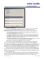
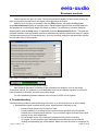
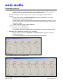
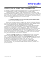
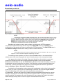
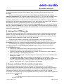
eela-audio
Broadcast products
Page 2 of 20
Copyright: RBKG & TRC
eela-audio
Broadcast products
TABLE OF CONTENTS
CONFIGURATION CAPS 2 DJIN RETRANSMISSION ............................................................ 4
1. Introduction ........................................................................................................................ 4
2. System requirements......................................................................................................... 5
3. General settings of DJin CAPS 2 Retransmission configuration ....................................... 6
4. Configuring playback and retransmission.......................................................................... 6
4.1. Configuring the insert player ....................................................................................... 6
4.2. Configuring the reserve player .................................................................................... 7
4.3. Configuring the basic retransmission channel ............................................................ 7
4.4. Configuring additional retransmission channel ........................................................... 9
4.5. Configuring switching parameters (mixing parameters).............................................. 9
4.6. Supporting of ASIO technology................................................................................. 12
5. Checking of settings ........................................................................................................ 12
6. Troubleshooting ............................................................................................................... 13
7. Switching under the schedule, pattern and DTFM-command.......................................... 15
8. Setting of the DTFM-decoder .......................................................................................... 17
9. Reserve switching. Detector of phone busy tones........................................................... 17
10. Technology of work in DJIN Retransmission configuration ........................................... 19
Copyright: RBKG & TRC
Page 3 of 20
eela-audio
Broadcast products
CONFIGURATION CAPS 2 DJIN RETRANSMISSION
1. Introduction
DJin “Retransmission” configuration is intended for automation of retransmission and inserting of
own programs at a regional radio station. Audio signal from one of inputs of an audio card
is driven to its output. Thus the inserting of regional program (commercials, news) takes place in
manual or automatic mode (under the schedule). The moment of starting of regional block playing
back can be either fixed or set under condition. Start per pattern recognized in the input signal is
also possible.
The configuration features reserve player providing broadcasting of a reserve signal
on output in case of absence of retransmission signal on input, the schedule editing window and
Jingle-machine for live programs support. Voice tracks handling, import of the schedule from
external scheduling system (for example, musical duplicator, traffic - manager, etc.) are also
available. Own broadcasting mode disables the switcher and only the signal from an internal player
is given to an output. Besides, the application supports routing of signals from 2 inputs
of an audio card to 1 output. It allows to insert the signal submitted not only by built - in player, but
also from own studio (local broadcasting). And due to the implemented support of ASIO technology,
switching can be made without a hardware delay.
DJin “Retransmission” configuration can work on any audio card. Switching of audio source
can be carried out both by hardware and software. Hardware switching gives the best quality
of audio and happens without delays, but requires good professional audio cards aligned for needs
of broadcasters. Actually this sector is represented by products of Digigram and Marian. In both
cases special approach is used for cards handling implemented individually by means
of API, given by developers of cards. If to estimate subjectively, cards of French firm Digigram give
better quality (although they are more expensive).
Hardware-software adjustment means use of standard Microsoft Windows interface for setting
of the signal level. Thus the level change command is directed through Microsoft Windows API to
the driver of an audio card which performs level setting (usually sending
a command directly to audio card). Quality of adjustment thus essentially depends on the
manufacturer of a card and of the quality of the card itself. Usually with low price products quality is
rather low; clicks, cracks and other artifacts are audible during switching. Besides, often the card
accessible through standard mixer Microsoft Windows, has no necessary regulators, or has
regulators with non-controllable level. The most qualitative and reliable variant for such application
is Marian TracePRO and Digigram VX222 cards. Also Terratec DMX6fire with external 5”25 breakout box, Creative Audigy ZS Platinum and Creative SBLive! are tested by us and can support the
needed tasks. While using ASIO 2.0 drivers also Marian MarcX, LynxOne and other cards can be
used.
Software adjustment of audio level means software preprocessing of audio data directly
before loading them in an audio card. Correspondingly a delay of about 1/10 seconds appears
Page 4 of 20
Copyright: RBKG & TRC
eela-audio
Broadcast products
at dynamic adjustment of level. On the other hand, quality of the processed signal will be higher
than quality of audio provided by any inexpensive audio card. Switching is also carried out
by the software - through recording with subsequent playback. Thus no hardware adjustments are
made, and the signal is simply recorded in the application buffer and played back through playback
device with a delay about one second.
Thus, you need to understand precisely which method of switching and levels adjustment you
are going to use. We can also add, that software switching and adjustment can be used with any
audio card (the only condition is availability of audio device in the list of Microsoft Windows audio
devices).
2. System requirements
The CAPS 2 software operates under the Microsoft Windows XP operating system (file system
NTFS) on Intel-compatible computers. The computer system performance requirements are
following:
RAM: + 128 / 256 MB (depending on software configuration of CAPS 2).
HDD: 50 Mb hard disk space are required for installation and start of work.
Current requirement are put proceeding from a final software configuration
of broadcasting automation system CAPS 2. The capacity of disk memory necessary for
storage of recorded sound in MPEG format is approximately calculated under the following
formula:
Volume (Mb) ≈ (Bit rate / 128) * 1300 * Number of storage days,
where Bit Rate is the parameter determining the level of signal MPEG-compression,
expressed in kilobits per second. The given formula results with 2% precision (in error to a
smaller extent) and does not depend on format of recording (mono, stereo) and sampling
frequency. Result of calculation represents the capacity of disk memory, necessary for audio
storage of the specified number of days expressed in Mbytes. For example, for storage of
month of audio with compression 128 kilobits / sec you need to have:
1 * 1300 * 30 = 39000 MB ≈ 40 GB
At audio recording without compression the memory capacity is approximately calculated as
follows:
Volume (GB) = 15 * Number of days * (Sampling frequency / 44100) * (Number of channels /
2),
where Sampling frequency is the frequency used for sampling; number of channels - 2 for
stereo and 1 for mono.
The given formula results with 1% precision (in error to a smaller extension).
Thus, for storage of one day of audio in format 44100 stereo 16 bits approximately
15 GB are required, for storage of a month - 450 GB.
Processor: they are different for different automation system components. Minimal
requirements are the same as for the operating system. It is recommended to use higher
figures for work of editing stations and loggers.
LAN with 100 Mb/s capacity (in a case if more than one workstation are used).
USB-ports must be available.
Keyboard and mouse must be available.
CAPS 2 software interface is designed for the screen resolution beginning from 1024x768
pixels.
Also the drivers of audio devices used in the system should have been installed and operate
normally.
Copyright: RBKG & TRC
Page 5 of 20
eela-audio
Broadcast products
3. General settings of DJin CAPS 2 Retransmission configuration
Here we will list basic moments, not concerning problems of adding of station in a complex, etc.
The program can support basic functions (except for retransmission) right after installation
and loading of configuration, according to default settings. Nevertheless, it is recommended
to perform the following actions:
Select DJin Retransmission configuration right after start of application (further
we suppose, that this step is already done, and the program is restarted).
Select the root directory. From the main menu use Service → Workstation settings →
Base Settings → Root path. After the first copy of the program gets access to this folder,
all necessary files will be automatically created there.
Create base settings. From the main menu use Service → Base Settings (just open the item
of the menu and confirm creating of file of settings using default values).
Select default audio format from the main menu Service → Global settings → Audio
format tab.
Select the PFL device. From the main menu use Service → Settings → PFL tab where one
of accessible PFL playback devices (not SP) can be selected. Selected device should not
be connected to the basic playback device which will be involved
in broadcasting in the future.
Select Jingle-machine device. Make right button click over the header of JM (Jinglemachine) and in the context menu select the Properties item.
4. Configuring playback and retransmission
To provide own broadcasting and retransmission you will have to configure:
Insert player (own program).
Reserve player.
Basic retransmission channel.
Additional retransmission channel (if used).
Switcher settings (mixing parameters).
Note, that CAPS 2 products support ASIO technology. More details on this question are given
in “Support of ASIO technology” section.
4.1. Configuring the insert player
Open Player properties window of the block player by clicking the right button
on a rectangular with a word Program and selecting the Properties command.
Page 6 of 20
Copyright: RBKG & TRC
eela-audio
Broadcast products
Fig. 1. Properties window of the block player
In the opened window specify the necessary playback device (dropdown list with the same
name). Activate Show VU meters, Show total length and Show transport bar checkboxes.
Besides, check both parameters in the Set by default section.
Remote control settings are described in details in CAPS 2 DJin user manual.
4.2. Configuring the reserve player
Configuring the reserve player should be done similarly to configuring of the insert player.
Fig. 2. Opening Properties window of retransmission switcher
4.3. Configuring the basic retransmission channel
For configuring of the retransmission module it is necessary to select (or create) the retransmission
channel. To open Properties window of retransmission switcher press the button
corner of retransmission window (Fig. 2).
Copyright: RBKG & TRC
in a right top
Page 7 of 20
eela-audio
Broadcast products
Fig. 3. Properties window of the retransmission switcher
Select the channel in the opened window (Fig.3) from the list of accessible channels in the
section Main retransmission channel. Initially (right after setting) this list is empty and
it is necessary to create retransmission channels on the basis of accessible hardware.
in the group of parameters Main
To create a retransmission channel press the button
retransmission channel. Also setting of retransmission channels is accessible from the main
menu Service → Hardware devices → Retransmission channel.
In the opened window Retransmission channels settings (Fig. 4) press the button Add. In
the opened window Retransmission channel settings (Fig. 5) specify the name of the channel,
and select record and playback devices from the dropdown lists with the same names. If you are
going to use software switching (for example, in case of recording from one card
to another), it is necessary to set the flag Program data transfer. If Digigram devices (and maybe
some other) are used (except for Digigram VX222), it is necessary to set parameter Keep playback
device open.
Page 8 of 20
Copyright: RBKG & TRC
eela-audio
Broadcast products
Fig. 4. Retransmission channels settings window
Fig. 5. Retransmission channel settings window
4.4. Configuring additional retransmission channel
Configuring additional retransmission channel is completely similar to the configuring of the basic
channel described above. The only difference is that in the Properties window
of retransmission player it is necessary to select the button
Extra retransmission channel.
located in group of parameters
4.5. Configuring switching parameters (mixing parameters)
After creation of retransmission channel you have to specify it as the used channel and also
to specify playback devices of players. After that you have to configure switching.
If you are using Marian cards (with non-wdm drivers) or Digigram cards (non-wdm)
as recording / playback devices, the software will automatically use hardware switching method.
Additional adjustment of Marian and Digigram devices could be done through a subgroup
Copyright: RBKG & TRC
Page 9 of 20
eela-audio
Broadcast products
of parameters Hardware devices of the Service menu. In both cases (audio cards from Marian or
Digigram) you have to specify what virtual devices are connected to busses and what physical
inputs / outputs will be used. In case of Antex audio cards use the software application from Antex
which is called AntexMixer.
If you are using standard devices with possibility to set playback and recording levels through
standard Microsoft Windows mixer, switching will be made by hardware-software method. Thus it is
necessary to specify evidently which mixer regulators are associated with this or that device. You
can do it from the main menu Service → Hardware devices → Audio Mixers (Fig. 6). In the
opened window Mixer controls setup you have to specify on a tab Audio devices and mixers the
regulator of the mixer associated to corresponding input
or output of the card. Unfortunately, there is no possibility to perform that automatically, therefore
this should be made manually.
Fig. 6. Mixer controls setup window
Generally you have to specify two regulators (or more, one for each used device): the first will
adjust the level of retransmitted signal coming to output of the card, and the second will adjust the
level of the signal reproduced by own players of DJIN Retransmission configuration. Besides it is
possible to specify a regulator of the recording device, which could be useful
in some cases.
Page 10 of 20
Copyright: RBKG & TRC
eela-audio
Broadcast products
Fig. 7. Audio device regulator window
First we will specify regulator responsible for transit of a signal to output. Press the Add
button. In the opened Audio device regulator window (Fig. 7) specify the type of the
Retransmission regulator, and then fill in all parameters, moving from the top to the bottom:
In the Audio device name dropdown list select audio playback device specified in the
settings of the Program player (insert player).
In the Audio mixer name list specify regulator associated with the given playback device.
In the Mixer line name list specify the regulator of a mixer responsible for adjustment of
output signal, coming from the input of a card to the output of selected playback device. In
SB family it is usually named Volume control: Line in.
In the Mixer control name list select regulator responsible for setting of signal level; usually
it is only one in the list and it named Line In Volume or simply Volume.
After setting up of parameters press OK button to close the window.
Now you have to specify, which regulator will be used for controlling of the signal of own
player. For this purpose repeat the described procedure starting from pressing of Add button
in the Mixer controls setup window (tab Audio devices and mixers), but specify Playback as the
type of regulator in the Audio device regulator window. In the Audio device name list select the
same device as you have done the first time. Then repeat the procedure described above, filling in
all fields from the top to the bottom. After finishing close the window by pressing OK button.
If you see in the process of settings that some lists are empty, for example, the Audio mixer
name list, this means that, most likely, the card used in your system does not allow signal control
by means of a standard audio mixer. In this case switching and level setting are possible only with
the help of hardware method.
If your card does not have internal mixer, accessible through standard Microsoft Windows
interface, you have to use software retransmission and level control. For this purpose you have to
specify audio devices with SP- prefix in the properties of the insert and reserve player, and
Copyright: RBKG & TRC
Page 11 of 20
eela-audio
Broadcast products
to set the flag Program data transfer in retransmission channel properties (Retransmission
channels settings window). Calibration of mixer regulators is made with the help of the Calibrate
mixer controls tab. Standard Microsoft Windows mixer allows setting level regulators to any value
in a range from 0 up to 65535. Each of the values corresponds to some level on output of the card.
Besides it is considered by default that number 65535 corresponds to the maximal level value, and
0 respectively to the minimal value. The window of mixer regulators calibration allows changing this
conformity: any level value can be compared to any point in the specified range (in dB). If value for
some of intermediate points is not specified,
it is calculated with the piecewise-linear approximation on known values.
4.6. Supporting of ASIO technology
ASIO technology (Audio Stream Input Output) has been created for improvement of work
of multichannel devices, particularly decrease of signal latency. This technology is being constantly
improved. For example, version 2.0 allows simultaneous use of several programs with one device,
support of direct monitoring (with a zero latency) of any input through any output.
Many audio cards manufacturers have implemented support of ASIO technology now.
It is necessary to note, that process of integration of various technologies is not fixed by the
standard, therefore different manufacturers can differently organize compatibility of standard and
ASIO technologies. In this connection it is recommended not to mix various technologies for one
device, and to use one of them: standard or ASIO technology.
For configuring retransmission in CAPS 2 DJin Retransmission through ASIO it is necessary,
that the audio card and drivers support the given technology. Also it is necessary, that the driver of
the used device is started at the start of the application. It is possible to provide that by means of
the menu Service - Hardware devices - ASIO. It is possible to see the list
of used channels in Properties of the loaded driver, and also to add / or remove available
channels, or to forbid using of any of them (without removal). Button Control panel serves for
access to the window of setting of ASIO parameters of the device, developed by the supplier
of the driver. In this window we configure the used recording and playback devices.
After finishing of setting of ASIO-devices it is necessary to set retransmission channels,
entering in the menu Service - Hardware devices - Retransmission Channel and selecting the
ASIO-device as recording and playback devices from the list. Then you have only to select the set
retransmission channel as the basic channel (accessible on pressing of the key with three dots to
the right of an inscription Retransmission in the properties of re-transmitter) and
to specify the ASIO-device in properties of own player.
5. Checking of settings
After performing of all settings we strongly recommend to check up the system performance.
Prior to that increase duration of crossfades of transition from retransmission and back for they will
be audible more clear. For changing of crossfades open the Properties window of retransmission
button in a right top corner of the retransmission window (Fig. 2)),
switcher (press the
represented on Fig. 3 and press Crossfades button.
It is necessary to select immediate return to retransmission at detection of closing jingle
in opened window Crossfades, and in items Fade-out when changing over from retransmission
to local program and Fade-in when changing over from local program to retransmission it is
necessary to set enough large values, for example 2000 ms.
Page 12 of 20
Copyright: RBKG & TRC
eela-audio
Broadcast products
Feed a signal to an input of a card. The signal presence indicator on input should change its
color to green and simultaneously the signal should appear at the output.
Add any file to a player, for example, from the Files window, and press the Play button
or the Retransmission button on transport panel. Retransmitted signal will be smoothly faded out
and playback of a soundfile will begin in a player in parallel. For performing of reverse transition
stop the player with the Stop button or repeatedly press the Retransmission button. There will be
a smooth transition from a playback material to retransmission with the subsequent stop of a player.
If all has taken place how it is described here, you have correctly configured retransmission system
and can start using of the program.
Fig. 8. Setting of crossfades in the window Crossfades
Fig. 9. Retransmission indicator changes its color to green
More detailed description of settings of the retransmission switcher is not in the scope
of the given manual. For example, it is not described here how to calibrate regulator of a mixer for
linear crossfade in dB scale, and also many other things.
For more detailed information address to the manual of CAPS 2 DJin system.
6. Troubleshooting
If there were any problems while performing of the test, try to find their solution in the list below.
Retransmitted signal is absent at the output, signal presence indicator is red.
o Check physical presence of a signal on input.
o Check possibility of recording from the record device specified in the Properties
window of the retransmission switcher. Try to record the signal from this device with
the help of any other application.
o Check whether some of the settings of standard mixer prevent recording
of a signal. For this purpose open standard Microsoft Windows mixer panel by
clicking corresponding sign of the taskbar. Make sure that the mixer is configured for
Copyright: RBKG & TRC
Page 13 of 20
eela-audio
Broadcast products
record from the same input on which you have submitted a signal. The example of
setting of mixer for Avance AC97 Audio card is shown below.
Retransmitted signal does not appear at the output, but the signal presence indicator
is green.
o Check setting of the mixer Retransmission regulator, performed by you earlier.
Probably, your settings are not correct.
o Check whether some of standard mixer settings prevent playback of a signal. For this
purpose open panel of standard Microsoft Windows mixer by clicking corresponding
sign of the taskbar.
o Check connection of the control equipment.
The player does not start playing back.
o The file has incompatible format.
o The program cannot open playback device specified in the settings of insert player.
Switching over is happening, but there is no crossfade.
o Check settings of the mixer Playback and Retransmission regulators. Probably,
they are not correct.
o Your card is not capable to make smooth adjustment of the signal.
Fig. 10. Example of settings of mixer, "Playback" section
Fig. 11. Example of settings of mixer, "Recording" section
Page 14 of 20
Copyright: RBKG & TRC
eela-audio
Broadcast products
7. Switching under the schedule, pattern and DTFM-command
So, the system is configured for performing of smooth switching over between retransmission and
own broadcasting. Now it is possible to check up switching over under the schedule.
Load any audio track into the player. Create the commercial block in the schedule, specify
parameters No sooner and No later in properties by setting airing time for it close to current time of
your computer. Fill it with suitable contents, for example, for a minute duration. Create copies of the
block, for example, 20 pieces every 2 minutes. Remove audio track from a player, it was necessary
only for prevention of loading of partly prepared schedule in a player.
NOTE
This method is necessary only in the demo version of CAPS 2 DJin Retransmission configuration
which does not store the schedule on a disk and has no opportunity to prepare it beforehand; in the fullfunctional version there is no need of such "tricks".
Blocks will be automatically loaded into the player, and start at the specified time. Switching
over will be done with crossfade. Take into account, that the program will not repeatedly play back
blocks already broadcasted even if you will change the computer clock setting.
To use switching over under pattern recognition you have to prepare patterns beforehand fragments of the retransmitted signal, recorded in uncompressed form, that determine points
of switching over to own program or return to retransmission. For this purpose record these
fragments on a hard disk without compression in WAV format. Then you have to divide the pattern
into 3 parts with marks Start and Stop with the help of the marking window: introductory area,
working area of recognition and crossfade area (Fig. 11). The duration of the working area should
be from 1 till 4 seconds. Duration of the first and third area should be not less than 0.3 seconds.
These are requirements of the system of patterns preparation.
Then press the Switcher settings button in the Properties window of the retransmission
in a right top corner of the retransmission window as shown
switcher (press the button
in Fig. 2). In the opened window with the same name press the Add pattern button and select one
of the previously prepared patterns. If modeling of the pattern was done successfully the program
will ask the name of the given pattern and add it in the list. After that you have
to specify what action should be carried out on the given pattern – switching over
to retransmission, or return from it. The pattern is considered as “opening” if On flag is set
in the table of patterns. The pattern with none of On or Off flags set does not participate in the
process of recognition.
Copyright: RBKG & TRC
Page 15 of 20
eela-audio
Broadcast products
Fig. 12. Division of a pattern into three areas
NOTE
The pattern file should have audible part duration from 1 till 4 seconds (format WAV, PCM, 44,1 kHz)
between marks Start and Stop, cutting off intervals approximately for 0,25 seconds from the beginning and
to the end. Marking Information should be stored in a file, therefore the Properties window (and the tab
Marking) need to be opened from the context menu of audio track in the Files module. Clicking the
Marking tab of the player window is not meaningful, because it is stored not
in a file in this case (the data are stored only in the schedule).
Switching can be done not only under a pattern, but also under a DTFM command.
It is possible to add DTFM image with the help of the Add DTFM button in the DTFM window.
In the top line of this window you have to configure the DTFM command. The Edit DTFM button in
the Switcher settings window allows editing of earlier created command.
NOTE
The DTFM command can contain not only figures from 0 up to 9 and letters A, B, C, D, E, F, but also
symbols "*" and "#" which are interpreted, respectively, as E and F.
For switching under a pattern you have to press the Auto button on the retransmission
switcher panel. After that the program will start to search patterns in the retransmitted signal.
Let's prepare the schedule for testing. Remove all blocks from the schedule, create new
sequence of blocks using the same method as described earlier, but do not set attributes
No sooner and No later; set only the Fixed time flag. Blocks will be loaded into player, but will be
broadcasted in a case of detection of a pattern. If the block has not been broadcasted during the
certain time, it will be removed from a player; the removal happens after the time, specified in
Service / Settings / Other / Schedule / Unload blocks.
Combination of broadcasting under a pattern with broadcasting under a time is also possible.
In this case you have to specify time of broadcasting to the block and to set the flag No sooner.
Time of broadcasting in this case is set obviously later than estimated time
of broadcasting, and then the block will be loaded in player beforehand and will stand in a queue
waiting for the playback command. If during this time a pattern will be recognized, the block will
start its playback; if the pattern will not be recognized for some reason (the jingle in the motherstation changed, strong noise or loss of a signal in retransmission line, failure
Page 16 of 20
Copyright: RBKG & TRC
eela-audio
Broadcast products
of recognition system), the block will be started later - at the time which is specified in block
properties.
Reaction on closing jingle depends on settings Return to retransmission if a closing
pattern is recognized of the crossfade settings window (see Fig. 7). In a case of immediate return
for retransmission, the system makes switching immediately after detection of closing DTMFsequence (or the pattern). In case of return for retransmission after finishing of current audio track
the switching over will be made after the element is over, during which the output DTMF sequence
was detected. Return for retransmission before the first musical audio track
is used if the commercial block contains elements of Commercial type, and at the end of the block
there is an element of Music type. Then in case of detecting of DTMF code during playback of the
commercial block, all commercial elements will be played back, and after the last of them the player
returns for retransmission.
8. Setting of the DTFM-decoder
The logic of switching under the DTMF-command is similar to logic of switching under recognized
pattern. The only essential difference is in the fact that the DTMF command can exist both in the
middle of jingle and also in any other its point while switching should be done in the end. For this
purpose the delay of operation is set at each DTMF command.
Configuring the module of recognition of DTFM commands, as well as configuring
of recognition of pattern, is made in the Switcher settings window which is opened from the
Properties window of the retransmission switcher with the help of the button with the same name.
For configuring of the module of recognition of DTMF-commands you have to specify the
following parameters in the DTFM decoder settings window, which is opened on pressing
of the DTFM setup button:
The minimal (maximal) duration of the symbol (pause) which is set 10 ms more (or less)
comparing to duration of a symbol (pause) of receiving signal.
If signals in the left and right channels are not in phase, it is necessary to inform decoder
about it by setting of corresponding parameter.
The level of received signal should be configured in conformity with a level of DTMF pulses.
Usually it is -12 dB.
The Signal to noise ratio sets percentage of DTMF signal in a mix of signal + noise
(in a band of DTMF signals). Limits of change of this parameter are 26 - 99 % (normal value
is 40 %). Excessive reduction of this parameter can lead to "false" operations of the
decoder, and increase of it - to loss of symbols in the message.
9. Reserve switching. Detector of phone busy tones.
Switching between retransmission and own program can take place not only under pattern
recognition and DTFM command, but also in case of loss of a signal on an input. Using of reserve
player is configured by means of separate group of parameters of the Properties window of the
retransmission channel; thus reserve switching can be carried out at the full loss of signal
on an input, and at replacement of input signal with phone busy tones (in a case when a signal from
telephone line is broadcasted).
NOTE
In current implementation the detector of phone rings works only at input signal digitization
frequency of 44100 Hz.
Copyright: RBKG & TRC
Page 17 of 20
eela-audio
Broadcast products
Detector of phone busy tones is a part of the module of signal presence recognition. At the
active Use Ring detector option the module recognizes presence of a signal on an input of the
retransmission channel by combination of two attributes: sufficient level of a signal and absence of
telephone busy tone.
For recognition of tone signal fixed narrow-band filter with a bandwidth 400 - 450 Hz is used
(see Fig. 12). For increase of working reliability of the device the signal is exposed to two-threshold
processing.
Fig. 13. Frequency characteristics of band filter
The decision on presence of busy tone is made if the following conditions are executed
simultaneously:
The signal level in a bandwidth of the filter exceeds the set threshold (setting Minimal ring
signal level (see Fig. 13).
The level of a signal outside of a bandwidth of the filter does not exceed the set threshold
(Maximal background level)).
Thus, if received signal (speech, music) includes the frequency close to frequency of phone
busy tone, detector does not snap into work, as simultaneously also other frequencies are
in a signal.
Page 18 of 20
Copyright: RBKG & TRC
eela-audio
Broadcast products
Fig. 14. The Settings of rings detector window
Except for thresholds, time parameters of phone busy tones are set (period, duration), and
also a mode of snap into operation - on time or on number of tones.
At selecting of snap into operation on time (the parameter (Switch after #ring) is off) the
decision on presence of phone busy tone is accepted with a delay set by the setting Switch on
time. The less is the time of snap into operation, the more is the probability of false switching of
detector. Real time of snap into operation can differ from set time in small range
(0 - 300 ms), if valid parameters of tones (period and duration) do not correspond to set
parameters. The decision that busy tones are stopped is taken after the signal of busy tone was
absent during a certain time (setting Switch off time). It is no need to set this parameter less, than
the maximal pause between tones, in this case detector switching on / off will take place on each
tone.
Described operating mode has one disadvantage: detector will snap into work on any tone
long enough irrespective of long pulses or short. To recognize short busy tones testifying that the
call is broken, the second variant of work of detector is used - with calculation of number
of tones. If for example the snap into operation on 2 tones is set, it means, that detector will give out
a signal about presence of tones upon termination of the second pulse. Thus the allowable limits of
the period and duration of tone are strictly taken into account. If the next pulse does not correspond
to the set options, it is ignored, and the counter of tones of the detector is reset.
As the detector of tones is a component of the detector of loss of a signal, it is necessary
to coordinate its settings with settings of time of switching over to reserve and back.
In modern automatic telephone systems signals of tones vary in their frequencies, therefore
the current version of the detector of tones, designed for a signal 440 Hz, is not universal.
10. Technology of work in DJIN Retransmission configuration
Work in CAPS 2 DJin Retransmission configuration is possible in 2 modes: in the retransmission
mode and in the mode of own broadcasting.
In the retransmission mode the player automatically broadcasts retransmitted signal (from one
of inputs of an audio card, or the local program from the program player, or a reserve from the
reserve player (if the signal on an input is absent). It is considered, that any time window
Copyright: RBKG & TRC
Page 19 of 20
eela-audio
Broadcast products
in the schedule is the retransmission time. If there is some block for set time in the schedule, this
block is loaded in the program player. The block loaded in the player can be broadcasted manually,
can be broadcasted automatically on time (if in block properties the time
of broadcasting is fixed and the method of broadcasting is specified, i.e. parameters No sooner
and No later are set), automatically in a case of pattern recognition in the input signal (the pattern
recognition module should be configured). Loading of blocks in a player occurs automatically before
some minutes up to an estimated time of broadcasting. By default this value is 5 minutes. It is
possible to set it from the main menu Service → Settings → Other → Schedule → Preload
blocks. The unloading of blocks is carried out in some minutes after approximate time of start (if
there is no rigid binding to time by flags No sooner or No later.
It is set in the same place, where loading of blocks is set.
In case there is no signal on input, but under the schedule there should be retransmission
there will be switching to the reserve player. And if commercial blocks have no rigid binding
to time and should be started on jingle, and there is no signal on input, blocks will
be broadcasted in the moment specified in properties of player, as though both flags No sooner
and No later are set.
In a mode of own broadcasting appearance of the block of players becomes simpler,
retransmission channels and reserve player disappear. In this mode only broadcasting under the
schedule is accessible, the control of an input line is not performed. This mode is convenient
in case of long own broadcasting when the logic of players’ interaction only prevents.
Page 20 of 20
Copyright: RBKG & TRC