1
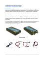
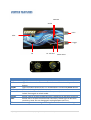
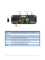
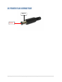
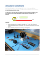
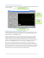
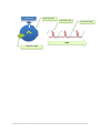
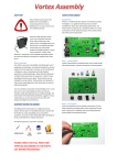
This manual and a proportion of its content is copyright of © Dynex Hobby 2015. All rights reserved. High speed rotors contain enough energy to cause damage to people and property. Manufacturer’s safety precautions MUST be adhered to during testing and operation of devices. Safety goggles must be worn during testing and operation of devices. High speed rotors can expel high velocity debris during an adverse event. WARNING! Never stand in front of or alongside a spinning rotor. Stand behind at a safe distance. Ensure bystanders are well away from the test article at a safe distance. NEVER run a rotor at full speed when balancing. Mounting cradles are not designed to restrain running devices at operational speeds. Run devices at the slowest possible speeds to avoid injury. Do not leave loose items nearby that can be caught by a spinning rotor. Secure all loose cables to prevent being caught in moving parts. Always stop running devices before working on them. Never place a limb in front of a rotor to stop it or slow it down. Fasten devices in secure mounts when operating at full speed. Follow the manufacturer’s instructions for correct device operation. Strobe light may cause seizures. Vortex was not designed for full size vehicles or industrial applications. Before you begin Your safety is your own responsibility, including proper use of equipment and safety gear, and determining whether you have adequate skill and experience. Improper use of modeling gear is dangerous, unless used properly and with adequate precautions, including safety gear. Some illustrative photos do not depict safety precautions or equipment, in order to show operating instructions more clearly. These products are not intended for use by children. These products are intended for radio control model applications and should never be used on industrial equipment. Use of our products and content on DynexHobby.com is at your own risk. It is your responsibility to make sure that your activities comply with applicable laws, including copyright. The United States Fire Administration (USFA) has a guide and many simple steps you can take to prevent the loss of life and property resulting from electrical fires. 1|P a ge © Copyright DynexHobby 2015 Introduction Vortex is a combined dynamic balancer and vibration analyzer for hobbyist. It is capable of balancing rotors and shaft assemblies to reduce wear and improve performance. The vortex system can operate as a stand-alone device or it can be connected to a PC for advanced analysis. This manual outlines the Vortex system and leads the operator through examples on its application. The Vortex system consists of the following parts. The analyzer or “black box” is the central processing unit. It collects and analyses vibration signals for dynamic balancing and spectrum analysis. Vortex is connected to a PC via the “microphone” port using a 3.5mm stereo cable. The system includes an accelerometer for measuring the acceleration levels of vibration. An infra-red detector and strobe light is also supplied for synchronizing the location of corrective weights required for balancing. Vortex Analyzer 3.5mm Stereo Cable 2|P a ge Accelerometer IR Sensor © Copyright DynexHobby 2015 Strobe Light Item Vortex IR Detector Accelerometer (ACC1) STROBE LIGHT 3|P a ge Quantity 9~12 VDC power supply Anodized aluminum case Dimensions (outer): 24mm(0.94")(H)x66mm(2.6")(W)x110mm(4.33")(L) Dimensions: 0.3" x 0.5" x 0.1" Operating voltage: 5.0V Supply current: 25mA Output format: analog voltage Optimal sensing distance: 0.125" (3 mm) Maximum recommended sensing distance: 0.25" (6 mm) Range: +/- 3g Sensitivity: 300 mV/g Small, low-profile package 1.8 V to 3.6 V operating range 10,000g shock survival Excellent temperature stability Output Type: Analog Typical Bandwidth (kHz): o 1.5kHz without capacitor o 50 Hz with capacitor installed Noise Density (µg/rtHz): 300 Intensity 25000~35000 MCD Viewing angle 25 degrees © Copyright DynexHobby 2015 Calibrate Strobe Gain Filter Trigger On Item On PC Transmit Strobe Calibrate Mode Select Trigger Gain Filter 4|P a ge PC Transmit Mode select Function Light illuminates when power is applied to Vortex Light illuminates when Vortex transmits data to PC. Activated by mode button. Light illuminates when Vortex is in Strobe Mode. Activated by mode button. Rotate clockwise/anticlockwise to zero accelerometer Press to active PC or Strobe modes. When pressed, the button remains locked. Press again to unlock mode. Rotate right to increase strobe sensitivity. Rotate left to decrease sensitivity. Rotate left to increase accelerometer sensitivity. Rotate right to decrease sensitivity. Note: Do not change gain setting between test runs. Rotate right to increase signal filtering. Rotate left to decrease filtering. © Copyright DynexHobby 2015 Filter Switch PC Connector Power Polarity S + - External Devices Item Power PC Connector Filter switch STR IR CAL ACC1 ACC2 Polarity 5|P a ge Function DC power supply. Recommended supply of 9 ~12 VDC. Center pin is “+” Stereo cable socket. This connects to PC sound card at “microphone input” Turn signal filtering on or off. Connection for LED Strobe Light Connection for infra-red reference detector Connection for accelerometer calibration Connection for accelerometer “ACC1”. For accelerometers that use 3V power supplies. ACC1 is supplied in the standard kit. Connection for accelerometer “ACC2”. For accelerometers that use 5V power supplies. This port currently not used. Black wire of connector always faces downward. © Copyright DynexHobby 2015 The diagram below illustrates the typical connections for the Vortex system. STEREO CABLE: Vortex communicates to a PC via 3.5mm stereo cable which is connected to the microphone input of the PC sound card. The stereo cable can be connected at any time, however the cable must be connected when performing balancing or vibration spectrum analysis. The cable is not required for the “Strobe Balancing Method”. ACCELEROMETER: Must be connected to ACC1. Port ACC2 is not currently used. ACC2 is reserved for future development of sensors. Warning! Do not connect the accelerometer to ACC2 as this could damage the sensor. IR SENSOR: Must be connected to the IR port. The IR Sensor is used during balancing only. It is not required for the “Strobe Balancing Method”. STROBE LIGHT: Only required for the “Strobe Balancing Method”. Accelerometer IR Detector Strobe Light Vortex is designed to be powered by a 9~12 V DC source (9VDC preferred). Do not use a mains power pack as tests have shown some packs can induce noise in the system. A battery such as a Lithium Polymer or Lithium Ion is recommended as this creates a noise free power source. Please follow manufacturer’s instructions on proper handling of batteries. 6|P a ge © Copyright DynexHobby 2015 Negative Positive 7|P a ge © Copyright DynexHobby 2015 Install the accelerometer on the rotor suspension system. It is best to install it in a horizontal position. The accelerometer can be positioned at any angle as desired, however the full scale deflection can be limited. The side that has the yellow label is positioned downward and glued to the device under test. Experiments have shown that attaching the accelerometer using “Blu-tack” is adequate. This side down Acc1 Sensor Direction CAUTION! 1. Secure any loose cables to the device using “Blu-tack” or tape. This will prevent cables from getting caught in the spinning rotor and reduces mechanical noise during testing. 2. Do not install any part of Vortex to moving or rotating parts. 8|P a ge © Copyright DynexHobby 2015 If you have the latest version of Vortex, ignore this section. The latest version of the hardware is self-calibrating. However if you have the older version, calibration can be performed as follows. To calibrate Vortex for the accelerometer location, follow the steps below: 1. 2. 3. 4. Connect accelerometer to Vortex ACC1 port. Install accelerometer on test article. Power on Vortex. Do not spin rotor. Attach a multimeter to the pins illustrated below. Turn the “calibrate” dial using a flat blade screw driver until the multimeter reads zero (±10mV is fine). 5. The Vortex is now calibrated and ready for use. 9|P a ge © Copyright DynexHobby 2015 Introduction DynexHobby provides analysis tools to determine the balance of rotors. There are two tools available listed below. These can be downloaded from www.dynexhobby.com. Name Dynex Analysis Image Scope Tool 10 | P a g e Application Used for all balance methods. This application runs under Microsoft Windows. Note that .NET 4 must be installed for this application to function. The scope tool can be used as an alternative to the Dynex Analysis package. It has a few additional features such as signal generation and vibration recording. © Copyright DynexHobby 2015 Features of vibration measuring software The following image illustrates the main features of the vibration measurement software (or “Scope” software). Changes Amplitude scale Channel 2: Measures Reference pulse Channel 1: Measures Vibration Changes Time scale How the software measures vibration for balancing The following image illustrates how the software measures vibration amplitude and phase. Vibration amplitude is typically measured by channel 1 in the oscilloscope software. An imbalance appears as a sinusoidal waveform. A marker is applied to the rotor such as a white line or a reflective strip. As the marker passes the IR Sensor, a pulse is registered. This pulse refers to a zero degree reference position on the rotor. The pulse is typically measured by channel 2 in the oscilloscope software. The time difference between the reference pulse and the sinusoidal waveform is referred to as the phase shift. Phase shift usually measured in degrees of rotation. Note: Sometimes a perfect waveform cannot be achieved due to external noise from bearings or loose mechanical connections. Vortex can filter such noise by switching on the filter and adjusting the “filter” dial on the front panel until a suitable waveform is obtained. Once the filter has been set, do not change for the remainder of the balancing operation. Additional filtering can be achieved using the DynexHobby software. 11 | P a g e © Copyright DynexHobby 2015 IR Detector Spinning Rotor Reference pulse M TIME Residual weight 12 | P a g e © Copyright DynexHobby 2015 Vibration Signal DynexHobby Vibration Meter Applications Dynex Hobby provides easy to use vibration meters. The meter was designed to interface directly with the Vortex unit. For simple balancing operations, the vibration meter can substitute for the “scope” software. There are two vibration meters available, an advanced meter and a basic meter which includes phase measurement. 13 | P a g e © Copyright DynexHobby 2015 DynexHobby Advanced Vibration Meter Application The advanced meter has most features that you would see in an oscilloscope. The meter allows the user to visualize the imbalance and IR signals in real time as well as display the frequencies of the imbalance. The advanced meter is a powerful tool for analyzing vibrations. It provides advanced signal filtering to isolate the imbalance signal from noise. Imbalance and IR signal display. Vibration magnitude Signal filtering and meter adjustment “High Frequency” cuts frequencies for Channel 1 above the value entered into the text box. “Low Frequency” cuts frequencies for Channel 1 below the value entered into the text box. “Calibration Factor” scales the magnitude. It also allows the operator to calibrate the vibration readings with an external source. “Max Scale” allows the operator to adjust the scale on the vibration meter. “Averaging” averages the measurements taken across the sample size. The larger the number the more averaging is performed. A larger average helps stabilize the meter dial. “Sample Rate” defines the sample rate of the signal. Units are samples/second. “Settings Box” allows the operator to select the source of the audio device. The audio device measures the vibration level from the Vortex. 14 | P a g e © Copyright DynexHobby 2015 “Tracking Filter” is an advanced feature that automatically filters for the imbalance signal by tracking the RPM. It removes other sources of noise and displays the imbalance signal. “Start” starts measuring and displaying the vibration signal. “Pause” stops measuring and displaying the vibration signal. DynexHobby Basic Phase Meter Application The phase meter automatically measures the phase angle between two signals. To enable the basic phase meter, click on “Basic Phase Meter” in the main menu. A new window will appear. Select the sound card or windows audio device and the sample rate. The software will automatically detect the devices available on your PC. The vibration meter will appear and proceed to record vibration data. No filtering is available with the basic meter. The follow describes the functions of the meter; Rotor running speed based on IR sensor. Sampling period of vibration signal Phase angle between vibration and IR sensor Vibration level “Sound card” button allows the operator to set the sampling rate of the vibration signal. “Start” and “Stop” buttons will start recording data and also pause the on screen readings. 15 | P a g e © Copyright DynexHobby 2015 “-Time” and “+Time” buttons will decrease on increase the sampling period of the vibration signal. “Vibration” level bar graph will indicate if the vibration level exceeds the operational limits of the Vortex unit. 16 | P a g e © Copyright DynexHobby 2015 Introduction Unbalanced rotors have relatively high force effects on bearings. High levels of unbalance can cause vibration, deformation, power degradation, friction and can degrade service life. In the case of a rotating shaft, the unbalance causes periodical forces to the suspension system which corresponds to the rotational speed. In other words it is synchronous with rotational speed (first order). In order to balance the rotor the correct running speed should be selected in the balancing instrument. The test speed is usually much lower than the operational speed for safety reasons. The correct running speed reduces the disturbance caused by the noise, harmonics, bearings and blade frequencies. The unbalance is radial in their line of action and it is a vector quantity. A vector has both magnitude and direction. The direction can be characterized by the phase between the unbalance vector (from the center of the shaft) and a vector to the reference point at the shaft (from the center of the shaft). Static Unbalance The general dynamic unbalance consists of the static (single plane) unbalance. This is when the mass center line is parallel and not coincidental with the rotational axis. This kind of balance exists in disk shape structures. It can be eliminated by a compensating weight. This method is appropriate for balancing ducted fan units, wheels or any disc shaped rotors. Coupled Unbalance The other type of unbalance is when a pair of weights are at two ends of the shaft but on opposite sides to each other (180°). The rotor is in static balance, but the centrifugal forces will produce a moment about the center of mass when the rotor turns. In this case, only a couple unbalance exists. The mass center line crosses the shaft axes at the center of gravity. 17 | P a g e © Copyright DynexHobby 2015 The couple unbalance can be compensated by two weights, which are positioned to counteract the couple unbalance at two planes. The ideal balancing task is to reduce the inhomogeneous mass distribution caused forces by adding or removing weights along the shaft. Suspension System (mounting cradle) The suspension system or the mounting cradle is crucial for balancing. The cradle allows the rotor system to oscillate back and forth near its natural state. The oscillation is important for Vortex to sense vibration and analyze the imbalance. Note: Mounting cradles are not supplied by Dynex Hobby. Cradles can easily be made from components supplied by your local hardware or electronics store. Each suspension system has a natural mode of vibration or natural frequency. If tests are conducted at the natural frequency (a specified RPM that cause’s natural vibration of the system), then the balancing results will be difficult to achieve. To avoid this, the following recommendations should be considered: 18 | P a g e © Copyright DynexHobby 2015 Run balancing at speeds above or below the natural frequency. This would be in a region where phase angle and amplitude are flat in the charts above. Soft suspension construction to provide a low resonance frequency. Allow the cradle to rock smoothly using frictionless supports. Teflon bearings or magnetic supports are ideal. Provide additional damping to reduce overshoot of the cradle. Foam rubber works well. Mechanically isolate the suspension system from the bench. This can be achieved by using a rubber mat. Determining the Suspension System Natural Frequency The following is a simple method for identifying the suspension system natural frequency. Mount rotor in cradle. Run motor incrementally from the lowest possible RPM to the highest safest speed. Please ensure safety when operating the rotor and follow manufacturer’s instructions. Protective gear is recommended. Plot the vibration amplitude and phase angle with incremental RPM. The natural frequency is identified by the peak in the vibration amplitude. A sample of the Vortex suspension system is shown below. The ideal running speed would be above 40Hz. A running speed of 60Hz would provide better results. 19 | P a g e © Copyright DynexHobby 2015 Method of Balancing The Vortex system uses a traditional approach used in industry to balancing. The following outlines the process; 1. Run the rotor at constant RPM. Note that the rotor speed should be kept the same during all tests. 2. Determine the original unbalance of the rotor. This can be measured as a voltage, acceleration, velocity or displacement. Vortex uses voltage. 3. Apply a trial weight and the unbalance is recorded again. This step is important as it creates a shift in the unbalance location. Dynamic balancers use this information to learn about the behavior of the system in order to correct for it. 4. Determine the correction weight required and position. 5. After the correction weight is applied, the unbalance is again measured. The unbalance remaining after balancing is called residual unbalance. 6. If the residual unbalanced is unacceptable then the process is repeated. The following methods are used by Vortex for balancing; 1. 2. 3. 4. Strobe Method Single Plane Balance 4 Point Balance Method 2 Blade Propeller Balance 20 | P a g e © Copyright DynexHobby 2015 When to use this method: A simple balance without relying on a PC. Limitations Accuracy is adequate but limited by user ability. Sensitive to mounting system setup. STEP 1 - Setup Setup device in mounting frame Ensure adequate spring and dampening is set. Ensure accelerometer is calibrated for mounting location. STEP 2 – Original Vibration (No weights) – First Run Run device at test speed. Example 40Hz. Turn Vortex on and press mode button to enter into strobe mode. The Vortex strobe light will flash twice. This indicates that Vortex has entered into the learning circuit mode. The learning circuit records the vibration level during the test for 10 seconds. Once this is completed, the green light will appear on the Vortex panel. Adjust the trigger dial until it produces a single solid line on the rotor. Record the vibration trigger level. Example trigger level for the first run was 4. Record the phase angle position (the angle the strobe line appears relative to the zero reference position). Draw the phase angle and trigger level on a balance sheet for the first run. See figure below. Balance sheet is available in the appendix. Direction of rotation 21 | P a g e © Copyright DynexHobby 2015 STEP 3 – Trial unbalance – Second Run Apply a test weight at the zero reference position. Example 0.3 gram. Run device at test speed. Example 40Hz. Adjust the trigger dial that produces a solid single line on the rotor. Record the vibration trigger level. Example trigger level for the second run was set to 5. Record the phase angle position (the angle the strobe line appears to the zero reference position). Draw the phase angle and trigger level on a balance sheet for the second run. STEP 4 – Calculate correction weight Draw a vector (line) from the second run to the first run. Measure the included angle between the correction vector and the first run. Example 66 degrees. Calculate the required correction weight as follows; Correction weight = First run trigger level / Correction vector length x Trial weight = 4 / 5 x 0.3 gram = 0.24 gram (approx.) The correction weight is applied in the opposite direction to the second run vector shift. For example, the second run vector shifted clockwise relative to the first run. The correction weight of 0.24 gram is then applied 66 degrees counter clockwise from the zero degree reference position. STEP 5 – Check balance Run device at test speed. Example 40Hz. Adjust the trigger dial that produces a solid single line on the rotor. Record the vibration trigger level. Example trigger level was set to 2. Since the trigger level is less than the original 4 then an adequate balance has been achieved. Note: It may not be possible to achieve a trigger level much less than this due to the sensitivity of the circuit. 22 | P a g e © Copyright DynexHobby 2015 When to use this method: Generally can be used on most occasions When you want precise balancing with minimal residual unbalance Strobe Method doesn’t provide adequate results. Recommended method as vibration phase, amplitude and residual imbalance can be calculated. Limitations Excessive vibration beyond Vortex capabilities Extreme levels of coupled unbalance Note this example uses the Scope software to illustrate vibration measurement. The Dynex advanced vibration meter can be used in the same way. Setup Setup device in mounting frame Ensure adequate spring and dampening is set. Ensure accelerometer is calibrated for mounting location. Connect Vortex to PC. Determine running speed that produces a nice sine wave on the oscilloscope display. STEP 1 – Original Vibration (no weights) Run device at test speed. Example 40Hz. Record vibration amplitude. Example 175.8mV Peak to Peak. Enter this value in Vortex Analysis Tool. Note: Do not change gain setting between test runs. 23 | P a g e © Copyright DynexHobby 2015 Measure phase shift. Example 265.8 degrees from start of reference pulse to first peak of sine wave. Enter this value in Vortex Analysis Tool. TIP A calculator has been provided in the Vortex Analysis Tool. Simply enter the time between the peaks of the reference pulse in the first cell. The second cell has the time between the first refence pulse and the first sine wave peak. The phase is calculated automatically between the two signals. 24 | P a g e © Copyright DynexHobby 2015 265.8 deg 175.8mV STEP 2 – Trial Unbalance Place a trial weight at the zero degree position. Example 0.29 gram at zero degrees positioned 23mm from axis of rotation. Run device at test speed. Example 40Hz. Record vibration amplitude. Example 245.5mV Peak to Peak. Enter this value in Vortex Analysis Tool. Measure phase shift. Example 192.7 degrees from start of reference pulse to first peak of sine wave. Enter this value in Vortex Analysis Tool. 25 | P a g e © Copyright DynexHobby 2015 STEP 3 – Determine Required Balance weight Required balance weight is read direct from Vortex Analysis Tool. Apply balance weight (example 0.198 gram) to hub at the required radial position (example 23mm). Note: The radial position can be changed to a new distance away from the axis of rotation if desired. 26 | P a g e © Copyright DynexHobby 2015 Radial distance Angular position 27 | P a g e © Copyright DynexHobby 2015 When to use this method: Generally can be used on most occasions When you want precise balancing with minimal residual balance Nonlinear conditions exist. Other methods do not provide adequate results. Limitations Excessive vibration beyond Vortex limits. Setup Setup device in mounting frame Ensure adequate spring and dampening is set. Ensure accelerometer is calibrated for mounting location. Connect Vortex to PC. Determine running speed that produces a nice sine wave on the oscilloscope display. STEP 1 – Original Vibration (No weights) Run device at test speed. Example 40Hz. Record vibration amplitude. Example 171.4mV Peak to Peak. Enter this value in the 4 Point Analysis Tool. Note: Do not change gain setting between test runs. 28 | P a g e © Copyright DynexHobby 2015 STEP 2 – Trial Unbalance 1 Place a trial weight at the zero degree position. Example 0.29 gram at zero degrees positioned 23mm from axis of rotation. Run device at test speed. Example 40Hz. Record vibration amplitude. Example 255.2mV Peak to Peak. Enter this value in the 4 Point Analysis Tool. 29 | P a g e © Copyright DynexHobby 2015 STEP 3 – Trial Unbalance 2 Place a trial weight at the 120 degree position. Example 0.29 gram at 23mm from axis of rotation. Run device at test speed. Example 40Hz. Record vibration amplitude. Example 192.4mV Peak to Peak. Enter this value in the 4 Point Analysis Tool. 30 | P a g e © Copyright DynexHobby 2015 STEP 4 – Trial Unbalance 3 Place a trial weight at the 240 degree position. Example 0.29 gram at 23mm from axis of rotation. Run device at test speed. Example 40Hz. Record vibration amplitude. Example 381.6mV Peak to Peak. Enter this value in the 4 Point Analysis Tool. 31 | P a g e © Copyright DynexHobby 2015 STEP 5 – Determine Required Balance weight Enter coordinates to position the black marker at the location where the red, blue and orange circles intersect. Required balance weight is read direct from the 4 Point Analysis Tool. Example apply 0.262 gram at the 70 degree position located 23mm from axis of rotation. 32 | P a g e © Copyright DynexHobby 2015 STEP 6 – Check final balance Run device at test speed. Example 40Hz. Record vibration amplitude. Example 50.37mV Peak to Peak. This means the final imbalance is 340% better than the original imbalance. 33 | P a g e © Copyright DynexHobby 2015 When to use this method: Generally can be used on most 2 blade propellers When you want precise balancing with minimal residual balance Other methods do not provide adequate results. Limitations Excessive vibration beyond Vortex limits. Setup Setup and secure propeller and motor mount to test stand. Attach accelerometer onto motor mount in direction of maximum vibration. Ensure accelerometer is calibrated for mounting location. Connect Vortex to PC. Determine running speed that produces a nice sine wave on the oscilloscope display (away from system natural frequency). STEP 1 – Original Vibration (No weights) Run device at test speed. Example 65Hz. Record vibration amplitude. Example 75.36mV. Note the value read from the software has been scaled up by 1000 for ease of entry. Enter this value in the 2 Blade Propeller Balance Tool. Note: Do not change gain setting on the Vortex between test runs. 34 | P a g e © Copyright DynexHobby 2015 STEP 2 – Trial Unbalance 1 Place a trial weight at the zero degree position. Example 0.03 gram at zero degrees positioned 70mm from axis of rotation. Run device at test speed. Example 65Hz. Record vibration amplitude. Example 42.72mV. Enter this value in the 2 Blade Propeller Balance Tool. 35 | P a g e © Copyright DynexHobby 2015 STEP 3 – Trial Unbalance 2 Place a trial weight at the 180 degree position. Example 0.03 gram at 70mm from axis of rotation. Run device at test speed. Example 65Hz. Record vibration amplitude. Example 150.5mV. Enter this value in the 2 Blade Propeller Balance Tool. 36 | P a g e © Copyright DynexHobby 2015 STEP 4 – Determine Required Balance weight Required balance weight is read direct from the 2 Blade Propeller Balance Tool. Example apply 0.042 gram at the 0 degree position located 70mm from axis of rotation. 37 | P a g e © Copyright DynexHobby 2015 STEP 5 – Check final balance Run device at test speed. Example 65Hz. Record vibration amplitude. Example 35mV. This means the final imbalance is 214% better than the original imbalance. With more effort the imbalance can be reduced much further by altering the balance weight. 38 | P a g e © Copyright DynexHobby 2015 When to use this method: Generally can be used on most items When you want precise balancing with minimal residual balance Other methods do not provide adequate results. Fine tuning results. Limitations Excessive vibration beyond Vortex limits. Setup Setup and secure propeller and motor mount to test stand. Attach accelerometer onto motor mount in direction of maximum vibration. Ensure accelerometer is calibrated for mounting location. Connect Vortex to PC. Determine running speed that produces a nice sine wave on the oscilloscope display (away from system natural frequency). STEP 1 – Trial Unbalance Place a trial weight at the zero degree position. Example 0.2 gram at zero degrees positioned 23mm from axis of rotation. Run device at test speed. Example 65Hz. Record vibration amplitude. Example 10.5mV. Enter this value in the Clock Balance Tool. Repeat Step 2 for all positions around the clock. The tool will display a linear map of the vibration amplitude as well as a polar map. This will help the user visualize the position of the residual mass. 39 | P a g e © Copyright DynexHobby 2015 STEP 2 – Determine Required Balance weight Required balance weight is read direct from the Clock Balance Tool. Example apply 0.035 gram at the 82.8 degree position located 23mm from axis of rotation. The position is shown on the chart at the right hand side of the window. 40 | P a g e © Copyright DynexHobby 2015 Introduction Vortex is capable of analyzing signals in real time. This can easily be performed using oscilloscope software equipped with this feature. Spectrum analysis is typically used as a fault finding tool when determining the source of unusual vibration. Setup Setup device in mounting frame Ensure adequate spring and dampening is set. Ensure accelerometer is calibrated for mounting location. Remove filter capacitor. Connect Vortex to PC. Switch “Filter” to off. Turn “filter dial” counter-clockwise until it stops. STEP 1 - Measuring Start rotor and run at constant speed. Switch oscilloscope software to “frequency” analysis. Click on the “peak hold” option to start recording data. Main RPM Sub Tones The spectrum analysis holds vast amounts of data of the device under test. The largest peak is normally the running speed of the rotor. Sub tones are typically lower than the main peak. These can be attributed to phenomena such as bearing noise, loose mechanical connections, aerodynamic and lubrication effects. 41 | P a g e © Copyright DynexHobby 2015 Introduction Vortex operates by converting vibration into an electrical signal. These signals are conditioned by onboard circuitry and sent to the PC soundcard. A normal signal when filtered will look like the one below. However when vibration levels exceed Vortex limits, the onboard circuitry will “clamp” the signal down to safe operating limits. This is designed to prevent damage to the PC soundcard. When a vibration signal reaches the physical limits of Vortex, the signal will appear distorted particularly at the signal peaks when viewed in the oscilloscope. A sample of distortion is shown below. Distortion may also appear as a square wave. Should the operator experience signal distortion, immediately turn down the “Gain” dial until the signal appears as a normal sine wave. If the distortion continues, cease operation of Vortex. 42 | P a g e © Copyright DynexHobby 2015 The table below summarizes some common issues observed during test. A great source for learning about vibration spectrum analysis can be found at this website, http://www.vibronurse.com 43 | P a g e © Copyright DynexHobby 2015 First run trigger level (O) Correction vector length (C) Trial weight (W) Correction weight = O / C x W 44 | P a g e © Copyright DynexHobby 2015 TERMS & CONDITIONS PLEASE READ THE FOLLOWING TERMS AND CONDITIONS OF USE CAREFULLY BEFORE USING DynexHobby.com. All users of this site agree that access to and use of this site are subject to the following terms and conditions and other applicable law. If you do not agree to these terms and conditions, please do not use this site. COPYRIGHT The entire content included in this site, including but not limited to text, graphics or code is copyrighted as a collective work under copyright laws, and is the property of DynexHobby.com. The collective work includes works that are licensed to DynexHobby.com. Copyright 2012, DynexHobby.com ALL RIGHTS RESERVED. Permission is granted to electronically copy and print hard copy portions of this site for the sole purpose of placing an order with DynexHobby.com or purchasing DynexHobby.com products. You may display and, subject to any expressly stated restrictions or limitations relating to specific material, download or print portions of the material from the different areas of the site solely for your own non-commercial use, or to place an order with DynexHobby.com or to purchase DynexHobby.com products. Any other use, including but not limited to the reproduction, distribution, display or transmission of the content of this site is strictly prohibited, unless authorized by DynexHobby.com. You further agree not to change or delete any proprietary notices from materials downloaded from the site. TRADEMARKS All trademarks, service marks and trade names of DynexHobby.com used in the site are trademarks or registered trademarks of DynexHobby.com WARRANTY DISCLAIMER This site and the materials and products on this site are provided "as is" and without warranties of any kind, whether express or implied. To the fullest extent permissible pursuant to applicable law, DynexHobby.com disclaims all warranties, express or implied, including, but not limited to, implied warranties of merchantability and fitness for a particular purpose and non-infringement. DynexHobby.com does not represent or warrant that the functions contained in the site will be uninterrupted or error-free, that the defects will be corrected, or that this site or the server that makes the site available are free of viruses or other harmful components. DynexHobby.com does not make any warrantees or representations regarding the use of the materials in this site in terms of their correctness, accuracy, adequacy, usefulness, timeliness, reliability or otherwise. Some states do not permit limitations or exclusions on warranties, so the above limitations may not apply to you. DEFECTIVE MERCHANDISE All defective merchandise from DynexHobby.com must be returned directly to us. An email must be sent to us informing us of defective items. All defective products can be returned for exchange under the following conditions: Merchandise must be returned in its original package within 30 days from the date of purchase. Do not write on the package. We will not exchange or refund any product with the product package having "defective" or anything else written on it. Returned items must be in resale condition, with the original packing material, unopened with all shipped items included. LIMITATION OF LIABILITY DynexHobby.com products are not toys nor intended to be used with a toy. All safety precautions recommended by manufacturers MUST be adhered to. DynexHobby.com shall not be liable for any special or consequential damages that result from the use of, or the inability to use, the materials on this site or the performance of the products, even if DynexHobby.com has been advised of the possibility of such damages. Applicable law may not allow the limitation of exclusion of liability or incidental or consequential damages, so the above limitation or exclusion may not apply to you. TYPOGRAPHICAL ERRORS In the event that a DynexHobby.com product is mistakenly listed at an incorrect price, DynexHobby.com reserves the right to refuse or cancel any orders placed for product listed at the incorrect price. DynexHobby.com reserves the right to refuse or cancel any such orders whether or not the order has been confirmed and your credit card charged. If your credit card has already been charged for the purchase and your order is cancelled, DynexHobby.com shall issue a credit to your credit card account in the amount of the incorrect price. TERM; TERMINATION These terms and conditions are applicable to you upon your accessing the site and/or completing the registration or shopping process. These terms and conditions, or any part of them, may be terminated by DynexHobby.com without notice at any time, for any reason. The provisions relating to Copyrights, Trademark, Disclaimer, Limitation of Liability, Indemnification and Miscellaneous, shall survive any termination. NOTICE DynexHobby.com may deliver notice to you by means of e-mail, a general notice on the site, or by other reliable method to the address you have provided to DynexHobby.com. 45 | P a g e © Copyright DynexHobby 2015 PARTICIPATION DISCLAIMER DynexHobby.com does not and cannot review all communications and materials posted to or created by users accessing the site, and is not in any manner responsible for the content of these communications and materials. You acknowledge that by providing you with the ability to view and distribute user-generated content on the site, DynexHobby.com is merely acting as a passive conduit for such distribution and is not undertaking any obligation or liability relating to any contents or activities on the site. However, DynexHobby.com reserves the right to block or remove communications or materials that it determines to be (a) abusive, defamatory, or obscene, (b) fraudulent, deceptive, or misleading, (c) in violation of a copyright, trademark or; other intellectual property right of another or (d) offensive or otherwise unacceptable to DynexHobby.com in its sole discretion. INDEMNIFICATION You agree to indemnify, defend, and hold harmless DynexHobby.com, its employees, agents, licensors and suppliers (collectively the "Service Providers") from and against all losses, expenses, damages and costs, including reasonable attorneys' fees, resulting from any violation of these terms and conditions or any activity related to your account (including negligent or wrongful conduct) by you or any other person accessing the site using your Internet account. THIRD-PARTY LINKS In an attempt to provide increased value to our visitors, DynexHobby.com may link to sites operated by third parties. However, even if the third party is affiliated with DynexHobby.com, DynexHobby.com has no control over these linked sites, all of which have separate privacy and data collection practices, independent of DynexHobby.com. These linked sites are only for your convenience and therefore you access them at your own risk. Nonetheless, DynexHobby.com seeks to protect the integrity of its web site and the links placed upon it and therefore requests any feedback on not only its own site, but for sites it links to as well (including if a specific link does not work). RETURNS When you using our website, and in a case of returned goods, you have to wrap it and pack it the best as possible, and you will held the responsibility of the package condition when it arrives back to us. We will NOT accept broken goods returned, that was broken while the shipment, or new item returns in a bad condition. We may apply 20% restocking fee for returned goods. 46 | P a g e © Copyright DynexHobby 2015