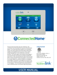
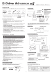
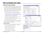
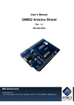
1
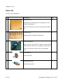
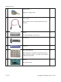
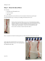
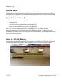
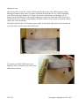
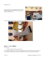
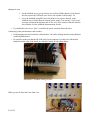
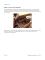
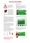
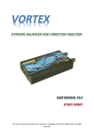
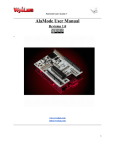
shrimpware.com
The Bread Box
for Raspberry Pi and Arduino AlaMode
Assembly and User Documentation
applies to bread box rev 8
Document Revision 19 May 2013
1 Of 24
Copyright (c) Shrimpware LLC 2013
shrimpware.com
Document History
19 May 2013
2 Of 24
Altered photos to show new potentiometer wiring.
Updated to Rev 10 of the Bread Box
Updated to Rev 5 of the GPIO LED board
Added section on Duemilanove
Copyright (c) Shrimpware LLC 2013
shrimpware.com
TERMS OF USE
Please read the entire agreement. By using this kit you agree to these terms. If you do not agree, please
do not use this kit. If you have any questions or concerns, feel free to contact us.
We are reasonable people, we hope you are too. If you are not, please do not buy or use our products or
our web site.
Safety
Technology and the laws and limitations imposed by manufacturers and content owners are constantly
changing. Thus, some of the projects described may not work, may be inconsistent with current laws or
user agreements, or may damage or adversely affect some equipment.
Your safety is your own responsibility, including proper use of equipment and safety gear, and
determining whether you have adequate skill and experience. Power tools, electricity, and other
resources used for these projects are dangerous, unless used properly and with adequate precautions,
including safety gear. Some illustrative photos do not depict safety precautions or equipment, in order
to show the project steps more clearly.
This project is not intended for use by children.
Use of these instructions and this kit is at your own risk. Shrimpware LLC disclaims all
responsibility for any resulting damage, injury, or expense. When a kit is connected to or used with
another piece of equipment it is your responsibility to make sure that connecting or using this kit will
not harm the other equipment.
It is your responsibility to make sure that your activities comply with applicable laws, including
copyright. Always check the webpage associated with a project before you get started. There may be
important updates or corrections! The United States Fire Administration (USFA) has a guide and many
simple steps you can take to prevent the loss of life and property resulting from electrical fires.
(http://www.usfa.dhs.gov/citizens/all_citizens/home_fire_prev/electrical.shtm)
If you feel uncomfortable or feel unable to safely assemble any project or kit, simply contact us to
return it for a full refund.
Accuracy of Information
We attempt to ensure that information in this document is complete, accurate and current. However we
cannot guarantee that all information is complete or current. You must use your own experience and
judgment as a guide when assembling or using this kit
3 Of 24
Copyright (c) Shrimpware LLC 2013
shrimpware.com
LIABILITY DISCLAIMER
Shrimpware LLC MAKE NO REPRESENTATIONS ABOUT THE SUITABILITY, RELIABILITY,
AVAILABILITY, TIMELINESS, AND ACCURACY OF THE INFORMATION, SOFTWARE,
PRODUCTS, AND SERVICES PROVIDED BY Shrimpware LLC FOR ANY PURPOSE. TO THE
MAXIMUM EXTENT PERMITTED BY APPLICABLE LAW, ALL SUCH INFORMATION,
SOFTWARE, PRODUCTS, AND SERVICES ARE PROVIDED "AS IS" WITHOUT WARRANTY
OR CONDITION OF ANY KIND. Shrimpware LLC AND/OR ITS SUPPLIERS HEREBY
DISCLAIM ALL WARRANTIES AND CONDITIONS WITH REGARD TO THIS INFORMATION,
SOFTWARE, PRODUCTS, AND SERVICES, INCLUDING ALL IMPLIED WARRANTIES OR
CONDITIONS OF MERCHANTABILITY, FITNESS FOR A PARTICULAR PURPOSE, TITLE AND
NON-INFRINGEMENT.
TO THE MAXIMUM EXTENT PERMITTED BY APPLICABLE LAW, IN NO EVENT SHALL
Shrimpware LLC AND/OR ITS SUPPLIERS BE LIABLE FOR ANY DIRECT, INDIRECT,
PUNITIVE, INCIDENTAL, SPECIAL, CONSEQUENTIAL DAMAGES OR ANY DAMAGES
WHATSOEVER INCLUDING, WITHOUT LIMITATION, DAMAGES FOR LOSS OF USE, DATA
OR PROFITS, ARISING OUT OF OR IN ANY WAY CONNECTED WITH THE USE OR
PERFORMANCE OF THE Shrimpware LLC PRODUCTS OR RELATED SERVICES, THE
PROVISION OF OR FAILURE TO PROVIDE SERVICES, OR FOR ANY INFORMATION,
SOFTWARE, PRODUCTS, AND SERVICES OBTAINED FROM Shrimpware LLC, WHETHER
BASED ON CONTRACT, TORT, NEGLIGENCE, STRICT LIABILITY OR OTHERWISE, EVEN IF
Shrimpware LLC OR ANY OF ITS SUPPLIERS HAS BEEN ADVISED OF THE POSSIBILITY OF
DAMAGES. BECAUSE SOME STATES/JURISDICTIONS DO NOT ALLOW THE EXCLUSION
OR LIMITATION OF LIABILITY FOR CONSEQUENTIAL OR INCIDENTAL DAMAGES, THE
ABOVE LIMITATION MAY NOT APPLY TO YOU. IF YOU ARE DISSATISFIED WITH ANY
PORTION OF THE Shrimpware LLC PRODUCTS, SERVICES, OR WEB SITE, OR WITH ANY OF
THESE TERMS OF USE, YOUR SOLE AND EXCLUSIVE REMEDY IS TO DISCONTINUE
USING THE Shripmware LLC products.
4 Of 24
Copyright (c) Shrimpware LLC 2013
shrimpware.com
Introduction
Congratulations on your purchase of the Shrimpware Bread Box for Raspberry Pi and Arduino
AlaMode. You about to embark on a fun filled frenzy of electro mechanical experimentation – all under
software control!
In the old days an experimenter needed a pile of transistors, capacitors, resistors, and a wire wrap gun
to make something. Then came the digital revolution and it could all be done with a system on a chip, a
soldering iron, and a bread board. The introduction of the Arduino microprocessor gave experimenters
the easy ability to sense and control the world using software. Then along came the Raspberry Pi and
everyone could have a real Unix based system in the palm of their hand. These two platforms have
made it easy for a software person to dabble in what used to be a hardware only world. The Raspberry
Pi gives you a Unix system to control. The Arduino gives you a way to talk to the real world of light,
temperature, and motion. The AlaMode circuit board from Wyolum is the perfect way to make these
two platforms dance together.
The typical experimenter's set up is a white bread board with a bunch of holes in it with wires sticking
everywhere. It can be quite intimidating to a person who only knows software. And today's
experimenters don't toil away alone in their basement – they want to take their creations to a friend's
house or a meet-up and show it off. Unfortunately those old bread boards don't travel well. The tangle
of wires easily come loose. At a meet-up you can spend more time figuring out which wire came loose
than you do showing off your great invention.
Experimenters have had a stable software platform for some time. The Bread Box provides a stable
physical platform for your work and introduces a new level of portability to your rig.
The Bread Box kit you have contains a number of servo motors, potentiometers (like a volume control),
and switches that will be wired up and held in place. You can place your finished Bread Box kit into a
real box and take it with you as you go experimenting.
While the Bread Box is designed for use with the Raspberry Pi and Arduino AlaMode, you can
certainly use it with any microprocessors you want. More adventurous experimenters might enjoy the
physical stability the Bread Box offers.
Be sure to check our web site for updates and links to information about the Bread Box:
www.shrimpware.com/breadbox
We hope you enjoy your new toy!
Jim Schrempp
5 Of 24
Copyright (c) Shrimpware LLC 2013
shrimpware.com
Parts List
In your kit you should have:
1.
Description
Qty
Bread Box base
1
It has holes for mounting either a Raspberry Pi or an
Arduino Duemilanove.
The other four holes are used to mount the Bread Box
top.
2.
Bread Box top
1
Mounting holes with labels etched into it.
3.
Micro servo motor
6
Each servo has a collection of “cranks” to mount on the
white shaft and a tiny screw to hold the crank in place.
Each servo also has two little screws to mount the
servo.
4.
Potentiometer
4
Linear 10K ohm
5.
Push button switch
1
Normally Open (off)
6 Of 24
Copyright (c) Shrimpware LLC 2013
shrimpware.com
6.
Toggle switch
1
Single Pole, Single Throw
7.
3-wire cables
3
You'll cut these to use with the potentiometers and
switches.
8.
Spacers
4
0.75 inch, threaded 6-32 each end
9.
6-32 screws
8
10.
Cable ties
4
11.
Wire numbering tags
12
The kit includes a set of them, more than you need.
Each column cuts in half – you only use three printed
numbers on each cable.
12.
Resistor
2
10k ohm axial lead
7 Of 24
Copyright (c) Shrimpware LLC 2013
shrimpware.com
You Will Need to Supply
5 volt Power supply, preferably capable of delivering 2 amps
Microprocessor, preferably a Raspberry Pi and an Arduino AlaMode
If you use a Raspberry Pi, then you might want to get the LED breakout kit from <<LINK HERE>>
Tools You Will Need
Regular Size Philips Screw Driver
Small Philips Screw Driver
Pliers
Wire Cutters
Wire Strippers (or a way to strip a few wires)
Soldering Iron and solder
12 inch ruler
8 Of 24
Copyright (c) Shrimpware LLC 2013
shrimpware.com
Step 1 – Number the Servos
You will need:
•
6 servos
•
Wire numbering tags 3, 5, 6, 9 10, 11
Wrap one wire number around the far end of each servo cable, about one inch from the three pin
connector.
Step 2 – Mount the Servos
You will need
•
6 servos and their little mounting screws
•
Bread Box Top
•
Small Phillips screw driver
Each servo has a number tag on the end of its cable. The top of the Bread Box has a number by each
rectangular hole. Start by placing the servo numbered 3 into the hole numbered D3. The servos go in
from the top so that the little “horns” sit on top of the Bread Box board. You will have to wiggle the
servo a little bit to get it to fit through the hole; a little gentle pressure is all you should need. Use the
mounting screws to secure the servo to the Bread Box top.
Mount the other servos making sure that the numbered servos go in the correspondingly labeled hole.
9 Of 24
Copyright (c) Shrimpware LLC 2013
shrimpware.com
Step 3 – Dress the Servo Wires
You will need
•
Bread Box top with mounted servos
•
Four wire zip ties
•
Wire cutters
This step is optional, but a nicely laid out set of wires makes the kit look more professional.
Turn the Bread Box top over so that you are looking at the bottom of the servos.
Take the cables from the left three servos (9, 10, 11) and gather them together.
Align the connectors so they are all together. Place one wire tie about two inches
from the end of the servo cables. Pull it snug, but don't damage the wires.
“Monkey tight, not gorilla tight” we like to say. See the photo to the left.
Now use the wire cutters to trim the end of the cable tie.
Place a second wire tie about five inches up the wires. Pull it snug and trim the end of the cable tie.
On the right side of the Bread Box top you do the same
thing with the other three servos (3, 5, 6). See the picture of
the finished dressed cables.
10 Of 24
Copyright (c) Shrimpware LLC 2013
shrimpware.com
Step 4 – Cut and Number the 3-conductor cables
You will need:
•
3 of the three conductor cables
•
12 inch ruler
•
Wire cutters
•
Wire numbering tags 1, 2, 3, 4, 5
Stretch the 3 cables out in front of you. For each cable you will need to measure closely, cut the cable
and then place a wire numbering tag on each near the connector. Follow the directions below:
(a) Use the ruler to measure one cable 7.5 inches from the very end. Cut this cable there. Do not
place a numbering tag on it.
(b) Measure another cable 6.5 inches from the very end. Cut this cable there. Put the wire
numbering tag of 1 on this cable.
(c) Measure another cable 6 inches from the very end. Cut it and put the tag 5 on it.
You now have four remaining pieces of cable. Label them as follows:
(d) The longest is about 5.5 inches. Put the wire numbering tag of 2 on it.
(e) The shortest is about 4 inches long. Put the wire tag of 4 on it.
(f) The remaining piece is about 5 inches long. Put the wire tag of 3 on it.
Whew, that was the hardest part!
11 Of 24
Copyright (c) Shrimpware LLC 2013
shrimpware.com
Step 5 – Mount the Switches
You will need:
•
The Bread Box top assembly
•
Push button switch
•
Toggle switch
•
Pliers
Take the toggle switch and remove the nuts on the shaft. Place the switch in the hole for A5. Discard
the split lock washer (or save it for another project!). Put the nut on top of the board and tighten the nut
by hand. Once the nut is snug, align the switch body to the same orientation as the servo bodies. Make
sure the two solder lugs are away from the servos. Now use the pliers to give the nut an extra little twist
to be tight.
Take the push button switch and remove the nuts from the shaft. Place the switch into the hole labeled
A4. Place the nut on the shaft. Tighten it up.
Step 6 – Cable up the Switches
You will need:
•
The Bread Box top assembly
•
The 3-wire cables labeled 4 and 5
•
Wire strippers
•
Wire cutters
•
Soldering Iron and Solder
•
Two resistors
Using the wire cutters, gentle nip between the wires at the cut end of the cable so that you can pull
them apart. Pull them apart for about one inch.
Strip the two outside wires. Do not strip the center wire.
12 Of 24
Copyright (c) Shrimpware LLC 2013
shrimpware.com
Trim both ends of the leads on each resistor so they are about 0.5 inches long.
Twist one end of the resistor together with the BLACK wire from one cable. You can use either end of
the resistor, it doesn't matter. Solder the connection. Do the same to the other cable with the other
resistor.
Taking the number 4 cable, solder the free end of the resistor to one of the lugs on the push button
switch. Solder the other stripped wire (WHITE) to the other lug of the push button.
Do the same for the number 5 cable and the toggle switch.
Step 7 – Mount the Potentiometers
You will need:
•
The Bread Box top assembly
13 Of 24
Copyright (c) Shrimpware LLC 2013
shrimpware.com
•
4 potentiometers
•
Pliers
Remove the nuts and washers from the shaft of each potentiometer. Place one potentiometer in each of
the holes labeled A0 – A3. Note that each potentiometer has a registration tab that fits into the
corresponding rectangular hole.
Place the flat washer and nut on each potentiometer shaft and tighten.
Step 8 – Cable up the Potentiometers
You will need:
•
The Bread Box top assembly
•
The remaining 3-wire cables
•
Wire cutters
•
Wire strippers
•
Soldering Iron and Solder
•
Place the Bread Box top assembly upside down in front of you.
Use wire cutters to gently nip between the wires on the end of each of the cables. Pull the cable wires
apart so that you have about one inch of free wire at the end of each cable.
Strip the ends from all three wires on all four cables.
Start with the cable labeled 3. Locate the potentiometer in the A3 hole. Solder the WHITE wire to the
CENTER lug of the potentiometer. Solder the BLACK wire to the RIGHT lug, as seen from the bottom
of the potentiometer. Finally, solder the RED wire to the LEFT lug.
Do this same process for the other three potentiometers, being sure to use the correctly numbered cable
for each potentiometer.
14 Of 24
Copyright (c) Shrimpware LLC 2013
shrimpware.com
Step 9 – Add Spacers To Bread Box Top
You will need:
•
The Bread Box Top Assembly
•
4 spacers
•
4 screws
•
Regular Size Philips head screwdriver.
Turn the Bread Box Top over so that you see the bodies of the
servos. Place a screw in one of the four mounting holes and
attach a spacer to the other side. Tighten it.
Do the same for the other three mounting holes.
Step 10 – Connect the Top to the Bottom
You will need:
•
The Bread Box Top assembly
•
The Bread Box Bottom assembly
•
4 screws
•
Regular Size Philips head screwdriver
15 Of 24
Copyright (c) Shrimpware LLC 2013
shrimpware.com
Place the Bread Box Bottom on the table in front of you with the etched side up.
Place the Bread Box Top assembly on the Bottom with the cables all coming out towards you between
the two closest spacers.
Place a screw in each mounting hole and attach the top to the bottom securely.
Step 11 – That's it!
You now have a fully assembled and ready to go Bread Box. Following are optional steps which
depend upon which experimental platform you own.
16 Of 24
Copyright (c) Shrimpware LLC 2013
shrimpware.com
Optional Steps
Your BreadBox is now complete! You can hook it up to whatever microprocessor suits your fancy. If
you happen to use a Raspberry Pi or an Arduino AlaMode, these steps show you how to hook them up.
Option 1 – Your Raspberry Pi
You will need
•
A Raspberry Pi
•
Two screws that fit it, about half an inch long, and nuts
•
Maybe two unthreaded spacers of about one eighth inch
Place a screw in each of the mounting holes for the Raspberry Pi. Put a spacer on each.
Orient your Raspberry Pi to the diagram etched on the Bread Box bottom. Carefully set it on the
protruding screws. Place a nut on each screw and LIGHTLY tighten them. If you tighten the screws too
much you can destroy your RPi.
Option 1a – RPi LED Breakout
You might have purchased the optional LED breakout for your Raspberry Pi. The LEDs for this board
press fit into the holes in the breadbox. This photo shows how the LED board fits the breadbox.
17 Of 24
Copyright (c) Shrimpware LLC 2013
shrimpware.com
These instructions are for Rev 5 of the LED board. Other Revisions of the LED board may require
different orientations of the cable. If you have a different Revision then be very careful in attaching
your LED board to your Raspberry Pi. Doing it incorrectly could damage your Raspberry Pi. In
general, on the LED board you will see that a single trace connects to each of the LEDs. This trace is
Ground and connects to Pin 6 on the Raspberry Pi GPIO connector. You may have to twist the cable to
achieve the correct orientation.
This photo shows the Rev 5 LED board in place with a 26 pin ribbon cable attached. Note that the red
side of the cable is to the center of the LED board.
To connect your GPIO LED board to your
Raspberry Pi you will need to put a twist in the
ribbon cable as shown.
18 Of 24
Copyright (c) Shrimpware LLC 2013
shrimpware.com
This photo shows the assembled breadbox top with the
LED board attached to the GPIO pins exposed by the
Arduino Alamode board.
For your reference this photo shows the twist needed to connect a Revision 4 LED board.
Option 2 – Your AlaMode
You will need:
•
Arduino AlaMode board from Wyolum.com
If you mounted a Raspberry Pi, then place your AlaMode board onto the RPi GPIO pins. Remember to
use the AlaMode rubber bumper on top of the RPi Ethernet connector to keep it from shorting out.
19 Of 24
Copyright (c) Shrimpware LLC 2013
shrimpware.com
If you don't have a Raspberry Pi, then we'll just hook up the AlaMode without mounting it.
When you assemble your AlaMode be sure to
•
Solder in header pins to the Servo Header section
•
Solder in header pins to the Analog Header section
•
Connecting up the servos
•
Take the servo cables labeled 3, 5, 6, 9, 10, 11 and press them each onto the AlaMode servo
header pin sets. Note that the pin set labeled 12 is a mistake on some AlaMode boards; the pin is
actually 11.
Be sure that the light orange control wires are all on the side of the Servo Headers closest to the
Arduino chip. See the photo below.
Illustration 1: AlaMode Servo Headers with Board Power Jumper in place
•
The servos in the Bread Box kit are very low power. You can drive them using AlaMode board
power. You should read the AlaMode documentation on where to place a jumper so that your
servos use board power.
•
If you power your AlaMode via the Raspberry Pi, you might find that you do not have enough
power to drive all the servos at once. The symptom will be that when the servos move the
Arduino, and possibly the Raspberry Pi will reboot. If this happens you have two choices:
20 Of 24
Copyright (c) Shrimpware LLC 2013
shrimpware.com
1. Set the AlaMode to use power from its own on-board USB connector. You should
also buy a powerful USB wall wart. We use one capable of delivering 2.1A.
2. Leave the AlaMode using RPi power but bring in servo power directly to the
AlaMode Servo Header from an external power supply. You can buy a 5vdc power
converter and attach the business end of it to a two wire connector that fits onto the
Servo Header. See the AlaMode documentation for this.
•
If you find that your servos “jitter” it could be the power situation discussed above.
Connecting up the potentiometers and switches.
•
Each potentiometer and switch has a labeled cable. The cables all plug into the Analog Headers
on the AlaMode board.
•
Be careful to make sure that the BLACK lead of each connector is on the side of the header
furthest from the edge of the board; it is labeled Ground. See the photo below.
Illustration 2: AlaMode Analog Headers
When you are all done this is the final view.
21 Of 24
Copyright (c) Shrimpware LLC 2013
shrimpware.com
Option 3 – Arduino Duemilanove
Your Bread Box also has mounting holes for the Duemilanove board. If you use this board we
recommend the Sainsmart Sensor Shield (www.sainsmart.com). This shield will give you header
connectors for the servos and the analog inputs.
22 Of 24
Copyright (c) Shrimpware LLC 2013
shrimpware.com
Option 3 – Put It In Your Own Box
You may find the kit so much fun for demonstrations that you'll want to take it to every meet-up. Of
course the careful maker will want to protect her kit – and also travel in style. Searching the internet
will uncover a number of cool wooden boxes to hold your Bread Box. I found one in my basement, and
here it is. Sweet!
Shrimpware now offers The Box for your Breadbox as a kit. The laser cut, cabinet grade plywood is the
perfect fit for your new toy. It is light weight, sturdy, and a real crowd pleaser. Check it out at
www.shrimpware.com/theboxkit
23 Of 24
Copyright (c) Shrimpware LLC 2013
shrimpware.com
Using Your Bread Box
The Arduino IDE comes with a number of sketches (C programs) that demonstrate reading from the
analog inputs and controlling servo motors.
Here's an example of controlling a servo motor to sweep as you turn a potentiometer:
http://arduino.cc/en/Tutorial/Knob
<<ADD LINKS TO MY SITE WITH SAMPLE PROGRAM AND INSTRUCTIONS>>
24 Of 24
Copyright (c) Shrimpware LLC 2013