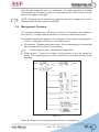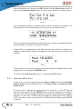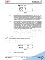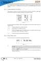
1
TEX502LCD TEX702LCD USER MANUAL VOLUME1 Manufactured by R.V.R ELETTRONICA S.p.A. Italy File Name: TEX502_702-LCD_GREEN-LINE_ING_1.0.indb Version: 1.0 Date: 29/11/2012 Revision History Date Version 29/11/2012 1.0 Reason First Version Editor J. H. Berti TEX502LCD TEX702LCD - User Manual Version 1.0 © Copyright 2012 R.V.R. Elettronica SpA Via del Fonditore 2/2c - 40138 - Bologna (Italia) Telephone: +39 051 6010506 Fax: +39 051 6011104 Email: [email protected] Web: www.rvr.it All rights reserved Printed and bound in Italy. No part of this manual may be reproduced, memorized or transmitted in any form or by any means, electronic or mechanic, including photocopying, recording or by any information storage and retrieval system, without written permission of the copyright owner. TEX502/702LCD Table of Contents 1. 2. 3. 3.1 3.2 4. 4.1 4.2 4.3 4.4 4.5 4.6 5. 5.1 5.2 5.3 5.4 5.5 6. 6.1 7. 7.1 7.2 7.3 7.4 7.5 7.6 7.7 7.8 Preliminary Instructions Warranty First Aid Treatment of electrical shocks Treatment of electrical Burns General Description Unpacking Features Frontal Panel Description Rear Panel Description Connectors Description Technical Description Quick guide for installation and use Preparation First power-on and setup Operation Management Firmware Optional Function Identification and Access to the Modules Identification of the Modules Working Principles Panel board Main board Telemetry board Power supply Power amplifier Control board Low pass filter card Bias card User Manual Rev. 1.0 - 29/11/12 1 1 2 2 2 3 3 3 5 6 7 9 11 11 13 15 17 22 25 25 26 26 26 27 27 27 28 28 28 TEX502/702LCD This page was intentionally left blank ii Rev. 1.0 - 29/11/12 User Manual TEX502/702LCD IMPORTANT The symbol of lightning inside a triangle placed on the product, evidences the operations for which is necessary gave it full attention to avoid risk of electric shocks. The symbol of exclamation mark inside a triangle placed on the product, informs the user about the presence of instructions inside the manual that accompanies the equipment, important for the efficacy and the maintenance (repairs). Make sure both are properly connected. 1. Preliminary Instructions Operation of this equipment in a residential area may cause radio interference, in which case the user may be required to take adequate measures. • General Warnings This equipment should only be operated, installed and maintained by “trained” or “qualified” personnel who are familiar with risks involved in working on electric and electronic circuits. “Trained” means personnel who have technical knowledge of equipment operation and who are responsible for their own safety and that of other unqualified personnel placed under their supervision when working on the equipment. “Qualified” means personnel who are trained in and experienced with equipment operation and who are responsible for their own safety and that of other unqualified personnel placed under their supervision when working on the equipment. The specifications and data contained herein are provided for information only and are subject to changes without prior notice. R.V.R. Elettronica S.p.A. disclaims all warranties, express or implied.While R.V.R. Elettronica S.p.A. attempts to provide accurate information, it cannot accept responsibility or liability for any errors or inaccuracies in this manual, including the products and the software described herein. R.V.R. Elettronica S.p.A. reserves the right to make changes to equipment design and/or specifications and to this manual at any time without prior notice. WARNING: Residual voltage may be present inside the equipment even when the ON/OFF switch is set to Off. Before servicing the equipment, disconnect the power cord or switch off the main power panel and make sure the safety earth connection is connected. Some service situations may require inspecting the equipment with live circuits. Only trained and qualified personnel may work on the equipment live and shall be assisted by a trained person who shall keep ready to disconnect power supply at need. This product is a radio transmitter suitable for frequencymodulation audio radio broadcasting. Its operating frequencies are not harmonised in designated user countries. Before operating this equipment, user must obtain a licence to use radio spectrum from the competent authority in the designated user country. Operating frequency, transmitter power and other characteristics of the transmission system are subject to restrictions as specified in the licence. R.V.R. Elettronica S.p.A. shall not be liable for injury to persons or damage to property resulting from improper use or operation by trained/untrained and qualified/unqualified persons. WARNING: The equipment is not water resistant. Any water entering the enclosure might impair proper operation. To prevent the risk of electrical shock or fire, do not expose this equipment to rain, dripping or moisture. Please observe local codes and fire prevention rules when installing and operating this equipment. WARNING: This equipment contains exposed live parts involving an electrical shock hazard. Always disconnect power supply before removing any covers or other parts of the equipment. Ventilation slits and holes are provided to ensure reliable operation and prevent overheating; do not obstruct or cover these slits. Do not obstruct the ventilation slits under any circumstances. The product must not be incorporated in a rack unless adequate ventilation is provided or the manufacturer’s instructions are followed closely. WA R N I N G : T h i s e q u i p m e n t c a n r a d i a t e radiofrequency energy and, if not installed in compliance with manual instructions and applicable regulations, may cause interference with radio communications. WARNING: This equipment is fitted with earth connections both in the power cord and for the chassis. User Manual • Notice concerning product intended purpose and use limitations. 2. Warranty La R.V.R. Elettronica S.p.A. warrants this product to be free from defects in workmanship and its proper operation subject to the limitations set forth in the supplied Terms and Conditions. Please read the Terms and Conditions carefully, as purchase of the product or acceptance of the order acknowledgement imply acceptance of the Terms and Conditions. For the latest updated terms and conditions, please visit our web site at WWW.RVR.IT. The web site may be modified, removed or updated for any reason whatsoever without prior notice. The warranty will become null and void in the event the product enclosure is opened, the product is physically damaged, is repaired by unauthorised persons or is used for purposes other than its intended use, as well as in the event of improper use, unauthorised changes or neglect. In the event a defect is found, follow this procedure: 1 Contact the seller or distributor who sold the equipment; provide a description of the problem or malfunction for the event a quick fix is available. Sellers and Distributors can provide the necessary information to troubleshoot the most frequently encountered problems. Normally, Sellers and Distributors can offer a faster repair service than the Manufacturer would. Please note that Sellers can pinpoint problems due to wrong installation. 2 If your Seller cannot help you, contact R.V.R. Elettronica S.p.A. and describe the problem; if our staff deems it appropriate, you will receive an authorisation to return the equipment along with suitable instructions; 3 When you have received the authorisation, you may return the unit. Pack the unit carefully before shipment; use the original packaging whenever possible and seal the package perfectly. The customer bears all risks of loss (i.e., R.V.R. shall not be liable for loss or damage) until the package reaches the R.V.R. factory. For this reason, we recommend insuring the goods for their full value. Returns must be sent on a C.I.F. basis (PREPAID) to the address stated on the authorisation as specified by the R.V.R. Service Manager. Rev. 1.0 - 29/11/12 / 28 TEX502/702LCD Units returned without a return authorisation may be rejected and sent back to the sender. 4 Be sure to include a detailed report mentioning all problems you have found and copy of your original invoice (to show when the warranty period began) with the shipment. Please send spare and warranty replacement parts orders to the address provided below. Make sure to specify equipment model and serial number, as well as part description and quantity. 3.1.2 R.V.R. Elettronica S.p.A. Via del Fonditore, 2/2c 40138 BOLOGNA ITALY Tel. +39 051 6010506 3. First Aid All personnel engaged in equipment installation, operation and maintenance must be familiar with first aid procedures and routines. 3.1 Electric shock treatment 3.1.1 If the victim is unconscious Lay the victim down on his/her back on a firm surface. • the neck and tilt the head backwards to free Do not stop chest compressions while giving artificial breathing. • Call for medical help as soon as possible. If the victim is conscious • Cover victim with a blanket. • Try to reassure the victim. • Loosen the victim’s clothing and have him/her lie down. • Call for medical help as soon as possible. 3.2 Treatment of electric burns 3.2.1 Large burns and broken skin Follow the first aid procedures outlined below. • • • Cover affected area with a clean cloth or linen. • Do not break any blisters that have formed; remove any clothing or fabric that is stuck to the skin; apply adequate ointment. • Administer adequate treatment for the type of accident. • Get the victim to a hospital as quickly as possible. • Elevate arms and legs if injured. If medical help is not available within an hour, the victim is conscious and is not retching, administer a solution of table salt and baking soda (one teaspoon of table salt to half teaspoon of baking soda every 250 ml of water). the airway system (Figure 1). Have the victim slowly drink half a glass of solution for four times during a period of 15 minutes. Stop at the first sign of retching. Do not administer alcoholic beverages. Figure 1 • If needed, open the victim’s mouth and check for breathing. • If there is no breathing, start artificial respiration without delay (Figure 2) as follows: tilt the head backwards, pinch the nostrils, seal your mouth around the victim’s mouth and give four fast rescue breaths. 3.2.2 Minor burns • Apply cold (not ice cold) strips of gauze or dress wound with clean cloth. • Do not break any blisters that have formed; remove any clothing or fabric that is stuck to the skin; apply adequate ointment. • If needed, have the victim change into clean, dry clothing. • Administer adequate treatment for the type of accident. • Get the victim to a hospital as quickly as possible. • Elevate arms and legs if injured. Figure 2 • / 28 Check for heartbeat (Figure 3); if there is no heartbeat, begin chest compressions immediately (Figure 4) placing your hands in the centre of the victim’s chest (Figure 5). Figure 3 Figure 4 Figure 5 • One rescuer: give 2 quick rescue breaths after each 15 compressions. • Two rescuers: one rescue breath after each 5 compressions. Rev. 1.0 - 29/11/12 User Manual TEX502/702LCD 4. General Description TEX502LCD and TEX702LCD, manufactured by R.V.R. Elettronica SpA, are transmitters for Frequency Modulated audio broadcasting in a frequency modulation able to transmit in the band between 87.5 and 108 MHz, in step of 10 KHz, with an RF output power adjustable up to a maximum of 500 and 700 W respectively into a 50 Ohm standard load. TEX502LCD and TEX702LCD are designed to being contained into a 19” rack box of 2HE. 4.1 Unpacking The package contains: 1 TEX502LCD or TEX702LCD 1 User Manual 1 Mains power cables The following accessories are also available from Your R.V.R. Dealer: • Accessories, spare parts and cables 4.2 Features The overall efficiency of TEX502LCD and TEX702LCD is better than 70% across the bandwidth, for this reason are part of RVR Green Line family. This performance characteristic is guaranteed in a range between +0.25 dB and -3 dB (+5% and -50%) referred to the nominal power of the equipment: for example from 250W to 525W in case of TEX502LCD or from 350W to 735W in case of TEX702LCD; outside these limits the equipment is able to work properly but can not guarantee an efficiency of 70%. These transmitters contain a low-pass filter that reduces the harmonic emission to provided for by international standards (CCIR, FCC or ETSI) and can be connected directly to the antenna. Two major features of TEX502LCD and TEX702LCD are compact design and user-friendliness. Design is based on a modular concept: the different functions are performed by modules that, for the most part, are connected through male and facilitates maintenance and module replacement. The RF power section of the TEX502LCD and TEX702LCD features a LD-MOSFET module delivering up to 800W output power. User Manual Rev. 1.0 - 29/11/12 / 28 TEX502/702LCD Operating frequency stability is ensured by a temperature-compensated reference oscillator and is maintained by a PLL (Phase Locked Loop) system. The transmitters will go into frequency lock within 30 seconds after power-on. The TEX502LCD and TEX702LCD can operate throughout the frequency bank with no need for calibration or set-up. An LCD on the front panel and a push-button board provide for user interfacing with the microprocessor control system, which offers the following features: • Output power setup. • Operating frequency setup. • Power output enable/disable. • Power Good feature (User-selectable output power alarm threshold). • Measurement and display of transmitter operating parameters. • Communication with external devices such as programming or telemetry systems via RS232 serial interface or I2C. Four LEDs on the front panel provide the following status indications: ON, LOCK, FOLDBACK and RF MUTE. The transmitter management firmware is based on a menu system. User has four navigation buttons available to browse submenus: ESC , , , ed ENTER. The rear panel features the mains input connectors, as well as audio input connectors and RF output connector, telemetry connector, protection fuses and two inputs for signals modulated onto subcarriers by suitable external coders, such as RDS (Radio Data System) signals commonly used in Europe. / 28 Rev. 1.0 - 29/11/12 User Manual TEX502/702LCD 4.3 Frontal Panel Description [1] [2] [3] [4] AIR FLOW ON LOCK FOLDBACK [5] R.F. MUTE [6] CONTRAST [7] ESC [8] [9] [10] ENTER [11] DISPLAY [12] POWER User Manual Air flow for the forced ventilation. Green LED, lit when the transmitter is working. Green led, lit when the PLL is locked on the working frequency. Yellow LED, lit when the foldback function is operating (automatic reduction of the delivered RF power). Yellow LED, lit when the transmitter’s power output is inhibited by an external interlock command. Display contrast adjusting trimmer (on the top of the equipment). Push button to exit from a menu. Push button to move in the menu system and to modify the parameters. Push button to move in the menu system and to modify the parameters. Push button to confirm a parameter and to enter in a menu. Liquid crystals display. ON/OFF switch. Rev. 1.0 - 29/11/12 / 28 TEX502/702LCD 4.4 Rear Panel Description [1] [2] [3] [4] [5] [6] PLUG VENTOLA R.F. OUTPUT 24 VDC IN- 24 VDC IN- INTERLOCK OUT [7] FWD EXT. AGC [8] RFL EXT. AGC [9] REMOTE [10]GSM ANT [11]PHASE ADJ [12]MODE/MPX IMP [13]SCA/RDS [14]MPX [15]MPX ADJ [16]SCA/RDS ADJ [17]RIGHT ADJ [18]RIGHT [19]FUSE BLOCK [20]R.F. TEST [21]MODEM [22]I2C BUS [23]RS232 [24]SERVICE [25]EXT REF 10MHz [26]PREEMPHASIS / 28 VDE plug for mains supply. Fan for the forced ventilation of the transmitter. RF output connector, N-type, 50Ω. Not used. Not used. Connettore BNC di interlock in uscita: quando l’eccitatore entra in modalità stand-by, il conduttore centrale, normalmente flottante, viene posto a massa Trimmer for the control of the delivered power in function of the FWD fold input. Trimmer for the control of the delivered power in function of the RFL fold input. DB15 connector for telemetry of the machine. Reserved for Future Uses - SMA connector for GSM Antenna. Pilot tone phase adjustment trimmer. Dip-switch to set the operation mode (STEREO or MONO) and the MPX input impedance, 50Ω or 10kΩ. BNC connector, SCA/RDS unbalanced input. BNC connector, MPX unbalanced input. Adjustment trimmer for MPX input. Adjustment trimmer for SCA/RDS input. Adjustment trimmer for the Right channel input. XLR connector, balanced Right channel input. Fuse carrier.Use a screwdriver to access the fuse. RF test output, approx. 13 dBm wrt the RF output power level. Not suitable for spectral analysis. DB9 connector connected to GSM modem (only with telemetry option). Normally not used, or used for customized functions (only with telemetry option). DB9 connector for direct serial communication or modem (only with telemetry option). DB9 connector for interconnection with other devices and for factory parameters programming (only for factory programming). Fine regulation trimmer for frequency transmission. Optionally, Sync signal input BNC connector for external devices. Dip-switch to set the preenphasys at 50 or 75 μs. The preenphasys setting is relevant only for the Left and Right inputs in stereo mode and for the mono input in mono mode, while MPX input is unaffected by this setting. Rev. 1.0 - 29/11/12 User Manual TEX502/702LCD [27]19 kHz PILOT OUT [28]SCA2 [29]SCA2 ADJ [30]LEFT-MONO ADJ [31]LEFT-MONO [32]IMPEDANCE BNC output for the 19 kHz pilot tone. This can be used for external devices (e.g. RDS coders) synchronization. BNC connector, SCA2 unbalanced input. Adjustment trimmer for SCA2 input. Adjustment trimmer for Left-Mono channel input. XLR connector, balanced Left-Mono channel input. Dip-switch to set the balanced input impedance, 600Ω or 10kΩ. 4.5 Connectors Description 4.5.1 RS232 Type: Female DB9 1 2 3 4 5 6 7 8 9 NC SDA SCL NC GND NC NC NC NC 4.5.2 Service (for programming of factory parameters) Type: Female DB9 1 2 3 4 5 6 7 8 9 NC TX_D RX_D Internally connected with 6 GND Internally connected with 4 Internally connected with 8 Internally connected with 7 NC 4.5.3 I2C Bus Type: Male DB9 1 2 3 4 5 6 7 8 9 User Manual NC TX_D RX_D Internally connected with 6 GND Internally connected with 4 Internally connected with 8 Internally connected with 7 NC Rev. 1.0 - 29/11/12 / 28 TEX502/702LCD 4.5.4 Left (MONO) / Right Type: Female XLR 1 2 3 GND Positive Negative 4.5.5 Remote Type: Female DB15 Pin Name Type 1 Interlock IN 2 Ext AGC FWD IN 3 GND 4 SDA IIC I/O 5 VPA Tlm ANL OUT 6 FWD Tlm ANL OUT 7 Power Good DIG OUT 8 GND 9 GND 10 Ext AGC RFL IN 11 SCL IIC I/O 12 IPA Tlm ANL OUT 13 RFL Tlm ANL OUT 14 On cmd DIG IN 15 OFF cmd DIG IN / 28 Rev. 1.0 - 29/11/12 Meaning By passes power if closed at GND Ext. signal,1-12V, for power limitation (AGC) Ground IIC communication serial data PA power supply voltage 3,9V F.S. Forward power 3,9V F.S. Open collector, enabled whenpower exceeds the set threshold Ground Ground Ext. signal.,1-12V, for power limitation (AGC) IIC communication clock PA power supply current 3,9V F.S. Reflected power 3,9V F.S. One grounded pulse (500 ms) enables power supply One grounded pulse (500 ms) disables power supply User Manual TEX502/702LCD 4.6 Technical Description TEX502LCD Parameters GENERALS U.M. Value Frequency range MHz 87.5 ÷ 108 Rated output power W Modulation type Operational Mode AC Supply Voltage DC Supply Voltage Active Power Consumption Overall Efficiency Input device Display Phisical Dimensions Ambient working temperature Frequency programmability Frequency stability Modulation capability Pre-emphasis mode Spurious & harmonic suppression Asynchronous AM S/N ratio Synchronous AM S/N ratio MONO OPERATION S/N FM Ratio Frequency Response Total Harmonic Distortion Intermodulation distortion Transient intermodulation distortion MPX OPERATION Composite S/N FM Ratio Frequency Response Total Harmonic Distortion Intermodulation distortion Transient intermodulation distortion Stereo separation STEREO OPERATION Stereo S/N FM Ratio Frequency Response Total Harmonic Distortion Intermodulation distortion Transient intermodulation distortion Stereo separation Main / Sub Ratio SCA OPERATION Frequency response Crosstalk to main or to stereo channel AUDIO INPUTS MPX balanced/Left Right MPX unbalanced/RDS SCA/RDS OUTPUTS RF Output Mains input voltage range Backup Input Voltage VAC VDC W % Notes 87.5 ÷ 108 500 700 Direct carrier frequency modulation Mono, Stereo, Multiplex 115 / 230 ±15% Direct carrier frequency modulation Mono, Stereo, Multiplex 80 ÷ 260 (*) 910 Typical 70 4 pushbutton Alphanumerical LCD - 2 x 16 483 2 525 -10 to + 50 From software, with 10 kHz steps ±1 150 Stereo, 180 Mono/MPX 0, 50 (CCIR), 75 (FCC) <75 (80 typical) ≥ 65 (typical 70) Front panel width Front panel height Overall depth mm HE mm °C WT from -10°C to 50°C ppm kHz μS dBc dB 650 Typical 70 4 pushbutton Alphanumerical LCD - 2 x 16 483 2 525 -10 to + 50 From software, with 10 kHz steps ±1 150 Stereo, 180 Mono/MPX 0, 50 (CCIR), 75 (FCC) <75 (80 typical) ≥ 65 (typical 70) dB ≥ 50 (typical 60) ≥ 50 (typical 60) dB > 78 (typical 83) > 80 (typical 85) dB >71 >73 dB >67 >68 dB % better than ± 0.5 dB (typical ± 0.2) < 0.1 (Typical 0.07%) better than ± 0.5 dB (typical ± 0.2) < 0.1 (Typical 0.07%) Referred to 100% AM, with no de-emphasis Referred to 100% AM, FM deviation 75 kHz by 400Hz sine, without de-emphasis RMS @ ± 75 kHz peak, HPF 20Hz - LPF 23 kHz, 50 μS de-emphasis Qpk @ ± 75 kHz peak, CCIR weighted, 50 μS de-emphasis Qpk @ ± 40 kHz peak, CCIR weighted, 50 μS de-emphasis 30Hz ÷ 15kHz THD+N 30Hz ÷ 15kHz Measured with a 1 KHz and 1.3 KHz tones, 1:1ratio, at FM 75 kHz Measured with a 3.18 kHz square wave and a 15 kHz sine wave at 75 kHz FM RMS @ ± 75 kHz peak, HPF 20Hz - no LPF, 50 μS de-emphasis 30Hz ÷ 53kHz 53kHz ÷ 100kHz THD+N 30Hz ÷ 53kHz THD+N 53kHz ÷ 100kHz Measured with a 1 KHz and 1.3 KHz tones, 1:1, modulation at FM 75 kHz Measured with a 3.18 kHz square wave and a 15 kHz sine wave at 75 kHz FM 30Hz ÷ 53kHz RMS @ ± 75 kHz peak, HPF 20Hz - LPF 23 kHz, 50 μS de-emphasis, L & R demodulated Qpk @ ± 75 kHz peak, CCIR weighted, 50 μS de-emphasis, L & R demodulated Qpk @ ± 40 kHz peak, CCIR weighted, 50 μS de-emphasis, L & R demodulated 30Hz ÷ 15kHz THD+N 30Hz ÷ 15kHz Measured with 1 KHz and 1.3 KHz tones, 1:1 ratio, modulation at FM 75 kHz Measured with a 3.18 kHz square wave and a 15 kHz sine wave at 75 kHz FM 30Hz ÷ 15kHz 40kHz ÷ 100kHz RMS, ref @ ± 75 kHz peak, no HPF/LPF, 0μS de-emphasis, with 67 kHz tone on SCA input @ 7,5kHz FM deviation RMS, ref @ ± 75 kHz peak, no HPF/LPF, 0μS de-emphasis, with 92 kHz tone on SCA input @ 7,5kHz FM deviation Connector Type Impedance Input Level /Adjust Connector Type Impedance Input Level Connector Type Impedance Input Level / Adjust Connector Type Impedance Input Level / Adjust RF Monitor Connector Impedance Connector Impedance Output Level Pilot output Connector MPX Monitor Impedance Output Level Connector Impedance Output Level AUXILIARY CONNECTIONS % < 0.02 < 0.02 % < 0.1 (typical 0.05) < 0.1 (typical 0.05) dB > 78 (typical 83) > 80 (typical 85) dB dB % % ± 0.2 ± 0.5 < 0.1 < 0.15 ± 0.2 ± 0.5 < 0.1 < 0.15 % < 0.05 < 0.05 % < 0.1 (typical 0.05) < 0.1 (typical 0.05) dB > 50 dB (typical 60) > 50 dB (typical 60) dB > 71 (74 typical) > 75 (78 typical) dB > 65 dB > 65 dB dB > 58 dB > 58 dB dB % ± 0.5 < 0.05 ± 0.5 < 0.05 % ≤ 0.03 ≤ 0.03 % < 0.1 (typical 0.05) < 0.1 (typical 0.05) dB dB > 50 (typical 55) > 40 (typical 45) > 50 (typical 55) > 40 (typical 45) Meets or exceeds all FCC and CCIR rules selectable by rear panel dip switches Meets or exceeds all FCC and CCIR rules ± 0.5 > 75 (typical 78 ) dB > 78 (typical 80 ) > 78 (typical 80 ) XLR F balanced or externally unbalanced 10 k or 600 -13 to +13 XLR F balanced or externally unbalanced 10 k or 600 -13 to +13 Selectable by rear panel dip switches continuosly variable XLR F balanced or externally unbalanced 10 k or 600 -13 to +13 XLR F balanced or externally unbalanced 10 k or 600 -13 to +13 Selectable by rear panel dip switches continuosly variable BNC unbalanced 10 k or 50 *-13 to +13 BNC unbalanced 10 k or 50 *-13 to +13 Selectable by rear panel dip switches for 75 KHz FM, externally adjustable 2 x BNC unbalanced 10 k *-8 to +13 2 x BNC unbalanced 10 k *-8 to +13 for 7,5 KHz FM, externally adjustable N type 50 BNC 50 approx. -60 N type 50 BNC 50 approx. -60 BNC BNC >5 k 1 >5 k 1 Ohm dBu dB dB Ohm dBu dB dB Ohm dBu dB dB Ohm dBu dB dB Ohm Ohm dB Ohm Vpp Referred to the RF output For RDS and isofrequency synchronizing purpose Ohm dBu 2 x BNC 2 x BNC DB9 F DB9 F Remote Interface Connector DB15F DB15F 115 / 230 ±15% (**) 653 650 0,998 VDE IEC Standard 80 ÷ 260 (*) 912 910 0,998 VDE IEC Standard On Mains Whithout condensing ± 0.5 Connector DC Power Input 19" EIA rack > 75 (typical 78 ) Connector User Manual (*) Full range (**) Internal switch dB Service AC Supply Voltage AC Apparent Power Consumption Active Power Consumption Power Factor Connector DC Supply Voltage DC Current Continuously variable by software from 0 to maximum dB Interlock POWER REQUIREMENTS AC Power Input FUSES Conditions TEX702LCD VAC VA W VDC ADC Rev. 1.0 - 29/11/12 Input and output for remote power inhibition (short is RF off) Factory reserved for firmware program IIC + 5 analog / digital inputs, 5 analog / digital outputs (*) Full range (**) Internal switch / 28 (*)max 25W (**) max 140W 1 External fuse F 16 A - 5x20 mm 1 External fuse F 16 A - 5x20 mm SCA/RDS Connector Type Impedance Input Level / Adjust TEX502/702LCD OUTPUTS RF Monitor RF Output Connector Impedance Connector Impedance Output Level Pilot output Connector MPX Monitor Impedance Output Level Connector Impedance Conditions Output Level Parameters GENERALS AUXILIARY CONNECTIONS Frequency range Interlock Rated output power Service Modulation type Remote Interface Operational Mode POWER REQUIREMENTS AC Supply Voltage ACSupply PowerVoltage Input DC Active Power Consumption Overall Efficiency Input device Display DC Power Input Phisical Dimensions FUSES On Mains Ambient working temperature On programmability services Frequency On PA Supply Frequency stability On Driver Supply Modulation capability MECHANICAL DIMENSIONS Pre-emphasis mode Phisical Dimensions Spurious & harmonic suppression Asynchronous AM S/N ratio Synchronous AM S/N ratio MONO OPERATION Weigh S/N FM Ratio TELEMETRY / TELECONTROL Remote connector inputs Frequency Response Remote connector outputs Total Harmonic Distortion Intermodulation distortion Transient intermodulation distortion Remote connector others MPX OPERATION VARIOUS Composite S/N FM Ratio Cooling Frequency AcousticResponse Noise Total Harmonic Distortion Intermodulation distortion Transient intermodulation distortion Stereo separation STEREO OPERATION Stereo S/N FM Ratio Frequency Response Total Harmonic Distortion Intermodulation distortion Transient intermodulation distortion Stereo separation Main / Sub Ratio SCA OPERATION Frequency response Crosstalk to main or to stereo channel AUDIO INPUTS MPX balanced/Left Right MPX unbalanced/RDS SCA/RDS OUTPUTS RF Output Connector Ohm Ohm dB Ohm Vpp Mains input voltage range AC Supply Backup InputVoltage Voltage AC Apparent Power Consumption Active Power Consumption Power Factor Connector DC Supply Voltage Front panel width DCpanel Current Front height Overall depth WT from -10°C to 50°C Front panel width Front panel height Referred to 100% AM, with no de-emphasis Overall Referred to 100% AM, depth FM deviation 75 kHz by 400Hz sine, without de-emphasis Chassis depth RMS @ ± 75 kHz peak, HPF 20Hz - LPF 23 kHz, 50 μS de-emphasis Analogical level Qpk @ ± 75 kHz peak, CCIR weighted, 50 μS Analogical level de-emphasis pulse Qpk @ ± 40 kHz peak, CCIR weighted, 50 μS pulse de-emphasis ON/OFF level 30Hz ÷ 15kHz Analogical THD+N 30Hz ÷level 15kHz level Measured withAnalogical a 1 KHz and 1.3 KHz tones, Analogical 1:1ratio, at FMlevel 75 kHz level Measured withAnalogical a 3.18 kHz square wave and OFF level a 15 kHz ON sine/ wave at 75 kHz FM RMS @ ± 75 kHz peak, HPF 20Hz - no LPF, 50 μS de-emphasis 30Hz ÷ 53kHz 53kHz ÷ 100kHz THD+N 30Hz ÷ 53kHz THD+N 53kHz ÷ 100kHz Measured with a 1 KHz and 1.3 KHz tones, 1:1, modulation at FM 75 kHz Measured with a 3.18 kHz square wave and a 15 kHz sine wave at 75 kHz FM 30Hz ÷ 53kHz RMS @ ± 75 kHz peak, HPF 20Hz - LPF 23 kHz, 50 μS de-emphasis, L & R demodulated Qpk @ ± 75 kHz peak, CCIR weighted, 50 μS de-emphasis, L & R demodulated Qpk @ ± 40 kHz peak, CCIR weighted, 50 μS de-emphasis, L & R demodulated 30Hz ÷ 15kHz THD+N 30Hz ÷ 15kHz Measured with 1 KHz and 1.3 KHz tones, 1:1 ratio, modulation at FM 75 kHz Measured with a 3.18 kHz square wave and a 15 kHz sine wave at 75 kHz FM 30Hz ÷ 15kHz 40kHz ÷ 100kHz RMS, ref @ ± 75 kHz peak, no HPF/LPF, 0μS de-emphasis, with 67 kHz tone on SCA input @ 7,5kHz FM deviation RMS, ref @ ± 75 kHz peak, no HPF/LPF, 0μS de-emphasis, with 92 kHz tone on SCA input @ 7,5kHz FM deviation Connector Type Impedance Input Level /Adjust Connector Type Impedance Input Level Connector Type Impedance Input Level / Adjust Connector Type Impedance Input Level / Adjust Connector Impedance Connector Impedance Output Level Pilot output Connector MPX Monitor Impedance Output Level Connector Impedance Output Level 2 x BNC unbalanced 10 k *-8 to +13 2 x BNC unbalanced 10 k *-8 to +13 N type 50 BNC 50 approx. -60 N type 50 BNC 50 approx. -60 BNC BNC >5 k TEX502LCD >5 k TEX702LCD 1 Value MHz 87.5 ÷ 108 2 x BNC 500 DB9 F Direct carrier frequency modulation DB15F Mono, Stereo, Multiplex 115 / 230 ±15% 115 / 230 ±15% (**) 653 650 650 70 Typical 0,998 4 pushbutton VDE IEC Standard Alphanumerical LCD - 2 x 16 87.5 ÷ 108 2 x BNC 700 DB9 F Direct carrier frequency modulation DB15F Mono, Stereo, Multiplex 80 ÷ 260 (*) 80 ÷ 260 (*) 912 910 910 70 Typical 0,998 4 pushbutton VDE IEC Standard Alphanumerical LCD - 2 x 16 Input and output for remote power inhibition (short isby RFsoftware off) Continuously variable from 0 to maximum Factory reserved for firmware program IIC + 5 analog / digital inputs, 5 analog / digital outputs (*) Full range (**) Internal switch (*) Full range (**) Internal switch 483 2 525 1 External fuse F 16 A - 5x20 mm -10 to + 50 From software, with 10 kHz steps ±1 150 Stereo, 180 Mono/MPX 0, 50 (CCIR), 75 (FCC) 483 (19") <75 (80 typical) 132 3HE ≥ 65 (typical 70) 525 ≥ 50 (typical 60) 501 19" EIA rack (*)max 25W (**) max 140W ppm kHz μS mm dBc mm dB mm dB mm 483 2 525 1 External fuse F 16 A - 5x20 mm -10 to + 50 From software, with 10 kHz steps ±1 150 Stereo, 180 Mono/MPX 0, 50 (CCIR), 75 (FCC) 483 (19") <75 (80 typical) 132 3HE ≥ 65 (typical 70) 525 ≥ 50 (typical 60) 501 kg dB about 24 > 78 (typical 83) about 24 > 80 (typical 85) FWD fold >71 REF fold RF ON RF>67 OFF better than ± Interlock 0.5 dB (typical ± 0.2) FWD 0.07%) < 0.1 (Typical REF <VPA 0.02 IPA < 0.1 (typical 0.05) Power Good I2Cbus FWD fold >73 REF fold RF ON RF>68 OFF better than ± Interlock 0.5 dB (typical ± 0.2) FWD 0.07%) < 0.1 (Typical REF <VPA 0.02 IPA < 0.1 (typical 0.05) Power Good I2Cbus > 78 (typical 83) Forced, with internal fan ±<75 0.2 ± 0.5 < 0.1 < 0.15 > 80 (typical 85) Forced, with internal fan ±<75 0.2 ± 0.5 < 0.1 < 0.15 W VAC VAC VDC VA W W % VDC mm ADC HE mm °C dB dB dB % % % dB dB dBA dB % % Notes % < 0.05 < 0.05 % < 0.1 (typical 0.05) < 0.1 (typical 0.05) dB > 50 dB (typical 60) > 50 dB (typical 60) dB > 71 (74 typical) > 75 (78 typical) dB > 65 dB > 65 dB dB > 58 dB > 58 dB dB % ± 0.5 < 0.05 ± 0.5 < 0.05 % ≤ 0.03 ≤ 0.03 % < 0.1 (typical 0.05) < 0.1 (typical 0.05) dB dB > 50 (typical 55) > 40 (typical 45) > 50 (typical 55) > 40 (typical 45) ± 0.5 > 75 (typical 78 ) dB > 78 (typical 80 ) > 78 (typical 80 ) XLR F balanced or externally unbalanced 10 k or 600 -13 to +13 XLR F balanced or externally unbalanced 10 k or 600 -13 to +13 Selectable by rear panel dip switches continuosly variable XLR F balanced or externally unbalanced 10 k or 600 -13 to +13 XLR F balanced or externally unbalanced 10 k or 600 -13 to +13 Selectable by rear panel dip switches continuosly variable BNC unbalanced 10 k or 50 *-13 to +13 BNC unbalanced 10 k or 50 *-13 to +13 Selectable by rear panel dip switches for 75 KHz FM, externally adjustable 2 x BNC unbalanced 10 k *-8 to +13 2 x BNC unbalanced 10 k *-8 to +13 for 7,5 KHz FM, externally adjustable N type 50 BNC 50 approx. -60 N type 50 BNC 50 approx. -60 BNC BNC >5 k 1 >5 k 1 Ohm dBu dB dB Ohm dBu dB dB Ohm dBu dB dB Ohm dBu dB dB Ohm Ohm dB Ohm Vpp Referred to the RF output For RDS and isofrequency synchronizing purpose Ohm dBu 2 x BNC DB9 F DB9 F On Mains On services On PA Supply for remote power inhibition (short is RF off) max 5 Vcc max 5 Vcc max 5 Vcc max 5 Vcc open collector ± 0.5 2 x BNC DC Power Input For P.A. A.G.C. purpose, min 0,5 Vcc For P.A. A.G.C. purpose, min 0,5 Vcc > 75 (typical 78 ) Connector 10 / 28 Meets or exceeds all FCC and CCIR rules selectable by rear panel dip switches 19" EIA rack Meets or exceeds all FCC and CCIR rules convertire in pollici compresi i connettori , compreso il pannello, escluse le maniglie, convertire in pollici escluso il pannello, esclusi i connettori, convertire in pollici dB Connector Connector AC Supply Voltage AC Apparent Power Consumption Active Power Consumption Power Factor Connector DC Supply Voltage DC Current Whithout condensing dB Service Remote Interface Referred to the RF output For RDS and isofrequency synchronizing purpose 1 Interlock POWER REQUIREMENTS AC Power Input for 7,5 KHz FM, externally adjustable Ohm U.M. dBu Connector RF Monitor AUXILIARY CONNECTIONS FUSES Connector Ohm dBu dB dB VAC VA W DB15F DB15F 115 / 230 ±15% (**) 653 650 0,998 VDE IEC Standard 80 ÷ 260 (*) 912 910 0,998 VDE IEC Standard 1 External fuse F 16 A - 5x20 mm 1 External fuse F 16 A - 5x20 mm Rev. 1.0 - 29/11/12 VDC ADC Input and output for remote power inhibition (short is RF off) Factory reserved for firmware program IIC + 5 analog / digital inputs, 5 analog / digital outputs (*) Full range (**) Internal switch User Manual (*)max 25W (**) max 140W TEX502/702LCD 5. Quick guide for installation and use This section provides a step-by-step description of equipment installation and configuration procedure. Follow these procedures closely upon first power-on and each time any change is made to general configuration, such as when a new transmission station is added or the equipment is replaced. Once the desired configuration has been set up, no more settings are required for normal operation; at each power-up (even after an accidental shutdown), the equipment defaults to the parameters set during the initial configuration procedure. The topics covered in this section are discussed at greater length in the next sections, with detailed descriptions of all hardware and firmware features and capabilities. Please see the relevant sections for additional details. IMPORTANT: When configuring and testing the transmitter in which the equipment is integrated, be sure to have the Final Test Table supplied with the equipment ready at hand throughout the whole procedure; the Final Test Table lists all operating parameters as set and tested at the factory. 5.1 Prepation 5.1.1 Preliminary checks Unpack the transmitter and immediately inspect it for transport damage. Ensure that all connectors are in perfect condition. The main fuse can be accessed from the outside on the rear panel. Extract the fuse carrier with a screwdriver to check its integrity or for replacement, if necessary. The fuse to be used is this type: @ 230 ±15% Vac TEX502/702LCD @ 230 Vac/115 Vac (1x) 8A tipo 5x20 Table 5.1: Fuses Provide for the following (applicable to operating tests and putting into service): √ Single-phase 230 ±15% Vac mains power supply for TEX502/702LCD, with adequate earth connection. √ For operating tests only: dummy load with 50 Ohm impedance and adequate capacity (500W for TEX502LCD or 700W for TEX702LCD as a minimum). √ Connection cable kit including: • Mains power cable • Coaxial cable with BNC connectors for interlock signal connection User Manual Rev. 1.0 - 29/11/12 11 / 28 TEX502/702LCD • RF cable for output to load / antenna (50 Ohm coaxial cable with N-type connector) • Audio cables between transmitter and audio sources. 5.1.2 Connections Connect the RF output of the transmitter to the antenna cable or a dummy load capable of dissipating amplifier output power. To begin with, set transmitter to minimum output power and switch it off. Connect the transmitter INTERLOCK IN input to the matching INTERLOCK OUT output fitted on R.V.R. Elettronica equipment to act as hybrid couplers. If your equipment is a different brand, identify an equivalent output. Connect the RF output to an adequately rated dummy load or to the antenna. WARNING: Electric shock hazard! Never handle the RF output connector when the equipment is powered on and no load is connected. Injury or death may result. Ensure that the POWER switch on the front panel of TEX502/702LCD is set to “OFF”. The transmitter has two switches: one is embedded in VDE socket for mains power cord and interrupts all mains power supply of the machine, while the second is on the front panel and acts by inhibiting the switching power supply of the machine. Connect the mains power cable to the MAINS connector on the rear panel. Note: the mains must be equipped with adequate earth connection properly connected to the equipment. This is a pre-requisite for ensuring operator safety and correct operation. Connect the audio and RDS/SCA signals from user’s sources to the transmitter input connectors. 12 / 28 Rev. 1.0 - 29/11/12 User Manual TEX502/702LCD 5.2 First power-on and setup Perform this procedure upon first power-up and each time you make changes to the configuration of the transmitter this component is integrated into. Note : Standard factory settings are RF output power off (Pwr OFF) and regulated output power set to upper limit (unless otherwise specified by customer). 5.2.1 Power-on When you have performed all of the connections described in the previous paragraph, power on the transmitter using the suitable power switch on the front panel. 5.2.2 Power check Ensure that the ON LED turns on. Equipment name should appear briefly on the display, followed by forward power and modulation readings. If the RF output is disabled, those readings will be zero. When the PLL locks to operating frequency, the LOCK LED will turn on. 5.2.3 How to enable the RF output Check output power level and set it to maximum level (unless it has already been set) from the Power Setup menu that you will have accessed by pressing the following sequence of key: ESC (opens Default Menu) ⇒ ENTER (hold down for 2 seconds) ⇒ SET ⇒ use keys to set bar to upper limit (figure 5.2 - menu 2). Check the state of the Pwr output power by the Fnc menu. If it is set to OFF, press ENTER to bring the selection to ON. 5.2.4 Output power level control Note: The transmitter incorporates Automatic Gain Control (AGC) and output power is modulated based on the power level set by the user and actual operating conditions, such as temperature, reflected power and other parameters. Please read section 5.3 for more details of RF power modulation. Access the Power Setup Menu pressing the following keys in the order: ESC (opens Default Menu) ⇒ ENTER (hold down for 2 seconds) User Manual Rev. 1.0 - 29/11/12 13 / 28 TEX502/702LCD Use the keys and in the SET menu to set transmitter output power; the setting bar at the side of SET provides a graphic indication of power setting; please consider that the forward power readout provided on the display (FWD: xxxx W) reflects actual output power reading, which may be lower than regulated power supply when Automatic Gain Control is running in power supply limitation mode (please read section 5.3 about RF power supply modulation for more details). Note: Output power may be set using the Pwr OFF control. In this condition, the output power readout (Fwd) on the display will read 0 (zero); the SET bar will reflect any adjustments you make using the keys and provides a graphic indication of how much power supply will be delivered the moment you return to Pwr On state. 5.2.5 Changing the Power Good alarm threshold Change Forward Power Good alarm setting PgD from the Fnc menu as desired (factory setting is 50%). 5.2.6 Setting equipment I2C address Change the IIC address in the MIX (Miscellaneous) menu as desired (factory setting is 01). 5.2.7 Adjustments and calibration The only manual adjustments are the level adjustments and the audio mode adjustment. The rear panel holds the trimmers for all transmitter inputs. Trimmer identification is printed on the rear panel. Input sensitivity can be set within the limits set out in the tables below through the trimmers: Input sensitivity: Input SCA1/ RDS SCA2 MPX Left/ Mono Right 14 / 28 Figure 6.2 Trimmer Sensitivity [13] [16] - 8 ÷ +13 dBu [28] [14] [29] [15] - 8 ÷ +13 dBu -13 ÷ +13 dBu [31] [30] -13 ÷ +13 dBu [18] [17] -13 ÷ +13 dBu Rev. 1.0 - 29/11/12 Notes Input level for 7,5 kHz overall deviation (- 20 dB) Input level for 75 kHz overall deviation (0 dB) User Manual TEX502/702LCD When setting input sensitivity, please consider that the default menu reports instantaneous modulation level and an indicator provides a 75 kHz reading. To ensure correct adjustment, apply a signal with the same level as user’s audio broadcast maximum level and then adjust using the trimmer until instantaneous deviation matches the 75 kHz reading. To set subcarrier input levels, you may use the same procedure and option “x10” available in the Fnc menu. With this option, modulation level is multiplied by a factor of 10, which means that default menu bar meter reflects a 7.5 kHz deviation. A special menu with separate indications of Left and Right channel levels and relating indicators of nominal levels for maximum deviation (75 kHz) is provided. • Preemphasis: ON 1 ON 2 3 4 50 ms 1 2 3 4 75 ms • L and R (XLR type) input impedance: ON 1 Switch 1: R XLR input impedance, ON = 600 W, OFF = 10 kW 2 Switch 2: L XLR input impedance, ON = 600 W, OFF = 10 kW • MPX input operation mode/impedance: ON 1 Switch 1: Mode of operation ON = Mono, OFF = Stereo 2 Switch 2: MPX input impedance, ON = 50 W, OFF = 10 kW 5.3 Operation NOTE: For better clarity, only the typical screens of TEX702LCD are reported below. TEX502LCD screens look the same except that full scale values are different. 1) Power on the transmitter and ensure that the ON light turns on. Equipment name should appear briefly on the display, quickly followed by modulation and forward power readings (Menu 1), provided that the transmitter is delivering output power. Menu 1 1b) To modify power level setting, hold down the ENTER button until opening the power setup menu. The edit screen will look like this: User Manual Rev. 1.0 - 29/11/12 15 / 28 TEX502/702LCD Menu 2 Next to SET indication, a bar provides a graphic display of preset output power. The filled portion of the bar is proportional to set power level. Example 100% output power 25% output power Full Bar 1/4 bar ≅ 700W in output (mod.TEX702LCD) ≅ 500W in output (mod.TEX502LCD) ≅ 175W output (mod.TEX702LCD) ≅ 125W output (mod.TEX502LCD) The bottom line provides instantaneous power reading (700W for TEX702LCD shown here), press button to increase level, press to decrease it. When you have achieved the desired level, press ENTER to confirm and exit the default menu. Please note that the setting is stored automatically; in other words, if you press ESC or do not press any keys before the preset time times out, the latest power level set will be retained. NOTE: This feature prevents the equipment from delivering maximum power as soon as output is enabled from menu 4, or in the event the equipment is already set to ON when you energise it. 2) Ensure that the equipment is not in a locked-out state. Press ESC to call up the selection screen (menu 3). Highlight Fnc and press ENTER to confirm and access the selected menu (menu 4). If PWR is set to OFF, i.e. power output is disabled, move cursor to PWR. Press ENTER and label will switch to ON, i.e. power output is enabled. Press ESC twice to go back to the default menu (menu 1). 3) Fine tune power setting from menu 2 (see description of item 1b) until achieving the desired value. WARNING: Equipment is capable of delivering more than rated output power (500/700 W for TEX502/702LCD respectively); however, never exceed the specified power rating. NOTE: If power is set to 0 W in the Power Setup Menu, the INTERLOCK OUT contact is activated and any external appliances connected to it are immediately inhibited. Next, you can review all operating parameters of the equipment through the management firmware. 16 / 28 Rev. 1.0 - 29/11/12 User Manual TEX502/702LCD Normally, the equipment can run unattended. Any alarm condition is handled automatically by the safety system or is signalled by the LED indicators on the panel or by display messages. NOTE: Standard factory settings are output power set to upper limit (unless otherwise specified by customer) and OFF. 5.4 Management Firmware The equipment features an LCD with two lines by 16 characters that displays a set of menus. The figure below provides an overview of equipment menus. The symbols listed below appear in the left portion of the display as appropriate: (Cursor) - Highlights selected (i.e. accessible) menu. (Filled arrow) - Editable parameter marker. This symbol appears in menus that take up more than two lines to aid browsing. (Three empty arrows) - Parameter is being edited. (Empty arrow) - Current line marker; the parameter in this line cannot be edited. This symbol appears in menus that take up more than two lines to aid browsing. Menu2 Menu1 Predefined menu Power Adjustment Menu Menu3 Selection Menu Menu4 Operation Menu Menu5 Power Menu Menu6 Power Amplifier Menu Menu7 Settings Menu Menu8 Miscellaneous Menu Menu9 Versions Menu Menu10 Channels Menu Figure 5.2 When the display is off, touching any key will turn on backlighting. User Manual Rev. 1.0 - 29/11/12 17 / 28 TEX502/702LCD When the display is on, pressing the ESC button from the default menu (menu 1) calls up the selection screen (menu 3), which gives access to all other menus: Menù 3 If the temperature alarm is enabled and the alarm threshold is exceeded, the following screen will be displayed (only if you are in the default screen): State 1 As soon as operating conditions are restored, power output is re-enabled with the same settings in use prior to the alarm condition. Under 20kHz, no modulation occurs. After a preset time of about 5 minutes (not editable), a NO AUDIO condition is indicated in the main screen, but power is not inhibited. State 2 To gain access to a submenu, select menu name (name is highlighted by cursor) using button or and press the ENTER button. To return to the default menu (menu 1), simply press ESC again. 5.4.1 Operation Menu (Fnc) In this menu, you can toggle transmitter power output On/Off, set deviation display mode and the threshold rate for Forward (PgD) or Reflected (PgR) Power Good. To edit an item, highlight the appropriate line using the and buttons and then press and hold the ENTER button until the command is accepted. This way, Pwr setting is toggled between On and Off and Mod setting is toggled between “x1” and “x10”. To edit the Power Good rate, simply select item “PgD” or “PgR” and edit its value using the UP and DOWN buttons; finally, press ENTER to confirm. 18 / 28 Rev. 1.0 - 29/11/12 User Manual TEX502/702LCD Menu 4 Pwr Enables (ON) or disables (OFF) transmitter power output. Mod Modifies modulation display (toggles between “x1” and “x10”). In “x10” mode, instantaneous deviation indication is multiplied by a factor of 10, and the bar meter on the default menu will reflect 7.5 kHz instead of 75 kHz. This display mode is convenient when you wish to display low deviation levels, such as those caused by pilot tone or subcarriers. PgD Modifies Power Good threshold for forward power. The Power Good rate is a percent of equipment rated power (500/700 W for TEX502/ 702LCD respectevely), not of forward output power. This means that this threshold set at 50% will give 250/350 W, respectively, regardless of set power level. The Power Good feature enables output power control and reporting. When output power drops below set Power Good threshold, the equipment changes the state of pin [7] of the DB15 “Remote” connector located on the rear panel. PgR Modifies Power Good threshold for reflected power. The Power Good rate is a percent of equipment rated power (50/70 W for TEX502/ 702LCD respectevely), not of reflected output power. This means that this threshold set at 5% will give 2,5/3,5 W, respectively, regardless of set power level. The Power Good feature enables output power control and alarm management. NOTE: This alarm does not trip any contacts in the DB15 “Remote” connector and is only available in systems equipped with telemetry. 5.4.2 Power menu(Pwr) This screen holds all readings related to equipment output power: Menu 5 Fwd Rfl User Manual Forward power reading. Reflected power reading. Rev. 1.0 - 29/11/12 19 / 28 TEX502/702LCD Note that these are readings, rather than settings, and cannot be edited (note the empty triangle). To change power setting, go to the default menu as outlined earlier. 5.4.3 Power Amplifier (P.A) Menu This screen is made up of four lines that can be scrolled using the buttons and shows the readings relating to final power stage: and Menu 6 Note that these are readings, rather than settings, and cannot be edited (note the empty arrow). VPA IPA Voltage supplied by amplifier module. Current draw of amplifier module. Eff Efficiency based on ratio of forward power to amplifier module power, in percent ( FWD PWR/(Vpa x Ipa) % ). Tmp Equipment internal temperature reading. 5.4.4 Setup Menu (Set) This menu lets you view and set operating frequency. Menu 7 F1 20 / 28 Operating frequency setup. Set a new frequency value and then press the ENTER button to confirm your selection; the transmitter unlocks from current frequency (the LOCK LED turns off) and will lock to the new operating frequency (LOCK turns back on again). If you press ESC or let the preset time time out, the previous frequency setting is retained. Rev. 1.0 - 29/11/12 User Manual TEX502/702LCD 5.4.5 Miscellaneous Menu (Mix) This menu lets you set equipment address in an I2C bus serial connection: Menu 8 IIC I2C address setting. The I2C network address becomes significant when the transmitter is connected in an RVR transmission system that uses this protocol. Do not change it unless strictly required. 5.4.6 Version Menu (Vrs) This screen holds equipment version/release information: Menu 9 Note that these are readings, rather than settings, and cannot be edited (note the empty arrow). Rel Dat Tab Firmware release information. Release date. Shows table loaded in the memory. 5.4.7 Channels Menu (L&R) Right and left channel input levels are displayed as horizontal bars as shown in the figure below. The bar meter reflects the level corresponding to a 100% deviation for each channel and provides a convenient reference when setting audio channel input levels. Menù 10 L R User Manual Left channel Vmeter. Right channel Vmeter. Rev. 1.0 - 29/11/12 21 / 28 TEX502/702LCD 5.5 Optional Function A range of options is available for the product to add certain functions and/or modify existing functions. Outlined below are the functions available at the moment, which must be specified on order. 5.5.1 FSK Option The FSK function generates periodic carrier frequency shifts to generate a Morsecoded station ID code. NOTE: This function is typically used in the USA. The factory setting for frequency shift is +10KHz and code repetition period is 60 minutes (please contact R.V.R. Elettronica if you need different settings), whereas station identified may be programmed by the user following the indications provided in section below. When the FSK option is fitted, an FSK submenu is added to the selection menu. Menu 11 Press the ENTER key when FSK is highlighted in the selection menu to access the FSK submenu: Menu 12 22 / 28 FSK Enables / disables FSK code transmission. Cod Shows the Morse code sent normally. Rev. 1.0 - 29/11/12 User Manual TEX502/702LCD 5.5.1.1 Changing the ID code User may change the FSK code used as a station identifier at any time. This procedure requires: • 1 RS232 male-female cable; • Hyper Terminal interface (make sure it has been installed together with Windows®) or equivalent serial communication software. A brief description of the procedure is provided below: • Connect the PC serial port COM to the SERVICE connector on the rear panel of TEX502/702LCD using a standard Male DB9 - Female DB9 serial cable. • Power on the transmitter; • Launch the serial communication software; • Set communication parameters as follows: Baud Rate: 19200 Data Bit: 8 Parity: None Stop Bit: 1 Flow control: None; • Activate Caps-Lock through the communication software and send string CODE followed by the 6-character station ID code followed by Enter. NOTE: To be treated as valid, the code must be made up of 6 alphanumeric characters and must contain no blank spaces; if acknowledged as valid, code is echoed back to the terminal, illegal codes are not echoed. 5.5.2 Power UP/DOWN Option The Power UP/DOWN option modifies the signal receive function for the signals present at the telemetry connector. RF section on / off control signals are treated as control signals for RF output power level to allow for UP/DOWN setting. The UP or DOWN command is provided by switching the corresponding signal at the connector to ground for at least 500mS (pin features internal pull-up to power supply). Configuration of DB15F telemetry connector (Remote): User Manual Rev. 1.0 - 29/11/12 23 / 28 TEX502/702LCD Pin Standard Function UP/DOWN Power Function 14 On cmd Up cmd Increases the RF power supply Enables the RF power supply 15 Off cmd Down cmd Reduces the RF power supply Disables the RF power supply 5.5.3 RDS Option Built-in RDS system with standard basic functions. NOTE: For further informations, read WINRDS manual 5.5.4 Internet Telemetry Option Telemetry system via the Internet. NOTE: For further informations, read /TLW manual 5.5.5 Telemetry Option with built-in modem Telemetry system via internal GSM modem. Battery and battery changer included. NOTE: For further informations, read /TLM manual 5.5.6 Telemetry Option without built-in modem Internal telemetry system without modem. 24 / 28 NOTE: For further informations, read /TLC manual Rev. 1.0 - 29/11/12 User Manual TEX502/702LCD 6. Identification and Access to the Modules 6.1 Identification of the Modules The TEX502/702LCD is made up of various modules linked to each other through connectors so as to make maintenance and any required module replacement easier. 6.1.1 TEX502/702LCD Upper view The figure below shows the equipment upper view with the various components pointed out. figure 6.1 [1] [2] [3] [4] [5] [6] Main Board & Stereo Coder Card Driver Card Panel Card Telemetry Card Bias Card, Control Card, Low Pass Filter Card & Power Amplifier Power Supply User Manual Rev. 1.0 - 29/11/12 25 / 28 TEX502/702LCD 7. Working Principles 7.1 Panel board The panel board contains the microcontroller (PIC18F452) that implements the equipment control software, the display and the other components needed to interface with the user. The board is connected with the other machine modules, both for power supply distribution and for the control and measures. 7.2 Main board The main board carries out the following functions: • Audio and SCA input treatment • Generation of carrier frequency • Modulation • R.F. amplification (Driver) The board also features a stereophonic coder. 7.2.1 Audio input section The audio input section contains the circuits that perform the following functions: • Input impedance selection • 15 kHz filtering of the left and right channel • Stereophonic Coding • Mono channel preemphasis • Mono, MPX and SCA channel mixing • Clipper (limits the modulating signal level so that the frequency deviation does not exceed 75 kHz) • Modulating signal measurement 7.2.2 PLL/VCO section This board section generates the modulated radiofrequency signal. It is based on a PLL scheme that uses an integrated MB15E06 type. 26 / 28 Rev. 1.0 - 29/11/12 User Manual TEX502/702LCD 7.2.3 Driver section Before passing to the final power amplifier, the RF signal is preamplified in this section by an BFG35 and an PD57006 transistor. When the transmitter is placed on stand-by, the driver is by-passed. 7.3 Telemetry board This board is designed to inform the user of the equipment operation state. All input and output signals are available on the DB15 connector. The same board also features the “INTERLOCK” BNC connector for disabling the device. By grounding the central pin, the output power is reduced to zero until the connection is removed. When an R.V.R. amplifier is used, this connector is linked to the power amplifier REMOTE or INTERLOCK by means of a BNC-BNC connection. In case of amplifier faults, the central conductor is grounded thus forcing the machine to enter in stand-by mode. 7.4 Power supply The TEX502/702LCD power supply unit is a switching-type unit whose +45 V main stabilizers for generating continuous +5 V, +18 V and -18 V voltages for supplying the other equipment circuits. Note that the power supply is a “direct from mains” type, or rather it is without a transformer, and it can be connected to any voltage between 90 and 260 V without any adjustments or manual settings. 7.5 Power amplifier The final power stage is enclosed in a totally shielded metal container fastened in the centre of the device. The RF signal coming from input power connectors, is measured by input directional coupler card and is then sent to the final stage that sees to its final amplifications up to 500W (for TEX502LCD model) or up to 700W (for TEX702LCD model). The amplification stage consists of two main blocks. In addition to the actual RF amplification, this circuit carries out the following functions: • Control of the power level in output, depending on the setting • Reduction of the power supplied when in presence of high-level reflected power • Measures of the current absorbed by the power amplifier • Measures of the temperature User Manual Rev. 1.0 - 29/11/12 27 / 28 TEX502/702LCD This board also features an RF sampling of approximately -44dB RF (for TEX502LCD model) / -46dB RF (for TEX702LCD model) with respect to the output, which is available on a BNC connector below the transmitter output connector. This sample is useful for verifying the characteristics of the carrier, but not for verifying those of the upper harmonics. 7.6 Control board The main function of this board is to check and correct the MOSFET polarization voltage of the RF amplifier section. It also provides the measurement of the absorbed current and contains a circuit for signaling power supply unit faults. If no alarms are present, the voltage is adjusted only depending on the set output power, with a feedback mechanism based on the reading of the power really delivered (AGC). The voltage is also affected by other factors, such as: • Excess of reflected power. • External AGC signals (Ext. AGC FWD, Ext. AGC RFL). • Excess of temperature. • Excess of absorbed current from the RF module. 7.7 Low pass filter card This card provide the low-pass filtering of the RF signal in output and measure the reflected and forward power output. 7.8 Bias card This card controls the bias voltage and contains AGC networks for forward power, reflected power, temperature, current and EXT AGC. 28 / 28 Rev. 1.0 - 29/11/12 User Manual ______________________________________________________________________________ ______________________________________________________________________________ ______________________________________________________________________________ ______________________________________________________________________________ ______________________________________________________________________________ ______________________________________________________________________________ ______________________________________________________________________________ ______________________________________________________________________________ ______________________________________________________________________________ ______________________________________________________________________________ ______________________________________________________________________________ ______________________________________________________________________________ ______________________________________________________________________________ ______________________________________________________________________________ ______________________________________________________________________________ ______________________________________________________________________________ ______________________________________________________________________________ ______________________________________________________________________________ ______________________________________________________________________________ ______________________________________________________________________________ ______________________________________________________________________________ ______________________________________________________________________________ ______________________________________________________________________________ ______________________________________________________________________________ ______________________________________________________________________________ ______________________________________________________________________________ ______________________________________________________________________________ ______________________________________________________________________________ ______________________________________________________________________________ ______________________________________________________________________________ ______________________________________________________________________________ ______________________________________________________________________________ ______________________________________________________________________________ ______________________________________________________________________________ ______________________________________________________________________________ ______________________________________________________________________________ ______________________________________________________________________________ ______________________________________________________________________________ ______________________________________________________________________________ ______________________________________________________________________________ ______________________________________________________________________________ ______________________________________________________________________________ ______________________________________________________________________________ ______________________________________________________________________________ ______________________________________________________________________________ ______________________________________________________________________________ ______________________________________________________________________________ ______________________________________________________________________________ ______________________________________________________________________________ ______________________________________________________________________________ ______________________________________________________________________________ ______________________________________________________________________________ ______________________________________________________________________________ ______________________________________________________________________________ ______________________________________________________________________________ ______________________________________________________________________________ ______________________________________________________________________________ ______________________________________________________________________________ ______________________________________________________________________________ ______________________________________________________________________________ ______________________________________________________________________________ ______________________________________________________________________________ ______________________________________________________________________________ ______________________________________________________________________________ ______________________________________________________________________________ ______________________________________________________________________________ ______________________________________________________________________________ ______________________________________________________________________________ ______________________________________________________________________________ ______________________________________________________________________________ ______________________________________________________________________________ ______________________________________________________________________________ ______________________________________________________________________________ ______________________________________________________________________________ ______________________________________________________________________________ R.V.R Elettronica S.p.A. Via del Fonditore, 2 / 2c Zona Industriale Roveri · 40138 Bologna · Italy Phone: +39 051 6010506 · Fax: +39 051 6011104 e-mail: [email protected] ·web: http://www.rvr.it ISO 9001:2000 certified since 2000 The RVR Logo, and others referenced RVR products and services are trademarks of RVR Elettronica S.p.A. in Italy, other countries or both. RVR ® 1998 all rights reserved. All other trademarks, trade names or logos used are property of their respective owners.