1
Advance / Advance Plus
User manual
Introduction
This manual is intended for the user of the device and
contains important information about safe and correct
use, maintenance and troubleshooting of the appliance.
The installer is responsible for installing and
commissioning the ventilation unit.
The following definitions are used in this manual to draw
attention to hazards, instructions or indications related to
people, products, installations and/or the surroundings.
ä Warning!
Indicates a hazard that can cause injury and/or severe
damage to the product, system or surrounding area.
ä Caution!
Instructions important for the installation, functioning,
operation or maintenance of the product. Failure to
observe these instructions can result in minor injury
and/or severe damage to the product, system or
surrounding area.
Note
Instructions important for the installation, functioning,
operation or maintenance of the product. Failure to
observe these instructions can result in minor damage
to the product, system or surrounding area.
Tip
Instructions that may be important for the installation,
functioning, operation or maintenance of the
product, but are not related to injury or material
damage.
3
Tip
Do not forget to register the product via the Heatrae
Sadia website. (www.heatraesadia.com/
warranty_registration)
Although this manual has been drawn up with the utmost
care, no rights may be derived from this document.
Heatrae Sadia reserves the right to modify products and
manuals without prior notice.
Due to our continuous product improvement process, the
illustrations in this document may not match the
delivered product. The latest version (if available) can be
downloaded from our website via www.heatraesadia.com.
Tip
Please keep the manual in its designated storage slot
on the ventilation unit.
4
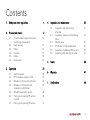
Contents
1.
Safety and other regulations
2.
Product information
12
2.1.
12
2.2.
2.3.
2.4.
2.5.
2.6.
3.
A comfortable living environment
and energy conservation
Heat recovery
Filters
Controls
Grilles
Accessories
6
14
14
14
18
19
Operation
20
3.1.
3.2.
3.3.
3.4.
20
22
24
26
3.5.
3.6.
3.7.
Control options
RF-VI wireless remote control
Wireless control switch with timer
Wireless control switch with
automatic control/timer
Wired three-position switch
Pairing and unpairing RF remote
controls
Pairing and unpairing RF sensors
4.
Inspection and maintenance
32
4.1.
32
4.2.
4.3.
4.4.
4.5.
4.6.
Inspection and maintenance
schedule
Inspecting, cleaning and replacing
filters
Maintenance
RF remote control maintenance
Inspection of additional RF sensors
Inspecting and cleaning air valves
34
36
36
36
37
5.
Faults
38
6.
Warranty
47
7.
Declarations
48
28
30
31
5
1. Safety and other regulations
ä
●
6
●
Warning!
The specifications and settings
of the ventilation system
comply exclusively with the
standards and statutes of the
country in which the
ventilation system is sold.
Applications outside this
country can lead to very
dangerous situations.
●
The entire system must
comply with the current
regulations as referred to in
this document and other
applicable documents
provided by the manufacturer.
All supplements, amendments
and regulations effective at
the time of installation are
applicable for all regulations.
●
●
●
After installation, no health,
safety or environmental risks
may be present in accordance
with the applicable CE
standards. This also applies to
other products included in the
system.
Do not use the product for
purposes other than those for
which it is intended, as
described in this manual.
Be careful when using
electrical appliances:
Never touch the appliance
with wet hands.
Never touch the appliance
when barefoot.
●
This product and/or system
may be operated safely by
children aged 12 years and
older and by people with
physical, sensory or mental
disabilities or a lack of
experience/knowledge if
under supervision or after
having received instructions
regarding safe use, and if they
are aware of the product
and/or system hazards.
7
●
●
●
8
Cleaning and maintenance by
the user may not be done by
children or people with
physical, sensory or mental
disabilities or a lack of
experience/knowledge
without supervision.
Do not allow children to play
with the product and/or
system.
Do not use the product in the
vicinity of flammable or volatile
substances such as alcohol,
insecticides, petrol etc.
●
●
Work may solely be performed
on the system by Heatrae
Sadia or recognised installers
in accordance with the
provisions laid down in this
manual. Only original
accessories and parts
produced by the manufacturer
may be used for these
purposes.
The system includes parts
which may be live. The installer
should take the following
steps before carrying out work
on an open system:
-
-
-
Disconnect power to the
appliance or system by
unplugging the power cord
at the wall socket.
Secure the appliance or
system against being
switched on accidentally.
The appliance includes
moving parts. When the
plug is removed from the
wall socket, these parts will
continue moving for a few
seconds. Therefore, you
should wait a minimum of
10 seconds before opening
the appliance after
removing the plug.
ä
●
●
●
●
Important!
The safety instructions must be
followed in order to prevent
physical injury and/or damage
to the product.
Maintenance instructions must
be followed to prevent
damage and excessive wear
and tear.
The product may not be
modified.
The product is only suitable for
use with a 230 V, 50 Hz AC
power supply system.
9
●
●
●
●
10
Ensure that the electrical
system to which the product is
connected meets the
necessary conditions.
Do not expose the product to
the elements.
Do not place any objects on
top of the device.
Inspect the product regularly
for faults. In the event of faults,
immediately contact your
installer or Heatrae Sadia.
●
●
●
●
Switch the product off if:
The product is not working
properly.
You want to clean the
outside of the product.
Ensure that the electrical
circuit does not become
damaged.
Do not use the device to
extract air from boilers,
heating systems etc.
Ensure that the device drains
into a sewer system which
leads outside, and is suitable
and installed for this purpose.
●
●
Ensure that air valves and
grilles are not obstructed, and
that they are clean.
Watch out for sharp and
protruding duct sections
during periodic cleaning of air
valves and grilles.
11
2. Product information
2.1. A comfortable living environment
and energy conservation
A comfortable living environment and energy
conservation are becoming increasingly important in
housing construction. The insulation of modern dwellings
is getting better all the time, but unfortunately good
insulation often comes at the expense of the indoor
climate. Without good ventilation, there is nothing to
stop damp, mould and dust mites, and the air in the
dwelling can quickly start to feel stale due to the
increasing CO2 (carbon dioxide) levels. Heatrae Sadia
develops appliances which manage the indoor climate
and take account of requirements for comfort and energy
consumption in homes.
The Advance and Advance Plus ventilation systems from
Heatrae Sadia are examples of these advanced
appliances.
12
The Advance and Advance Plus are balanced ventilation
systems with heat recovery. These ventilation units have
separate air streams for supply air and exhaust air.
The units ventilate several rooms in the dwelling. Stale or
humid air is extracted from the kitchen, bathroom, toilet,
and any indoor storage spaces or washrooms ("wet
rooms") through ducts.
The living room, bedrooms and hallway can also be
connected with ductwork, but in these areas there is no
air exhausted, just fresh air supplied.
To ensure good air distribution, the extraction and supply
points in the ventilated rooms are fitted with extractor
valves and supply grilles.
The Advance and Advance Plus help to reduce humidity
in your bathroom, keep the toilet smelling fresh and
remove cooking odours from the kitchen.
13
2.2. Heat recovery
2.3. Filters
Before the stale air is discharged outside, it is filtered and
passes through the heat exchanger. The fresh outside air
is also filtered and passes through the heat exchanger
before entering the dwelling. In the heat exchanger, the
two air streams pass alongside each other but are not
mixed together. This allows heat from the exhaust air to
be transferred to the fresh supply air, so this energy is not
lost.
The Advance and Advance Plus have two filters, one for
each air stream. Both filters are positioned in the
ventilation unit so that they protect the exchanger against
soiling. In addition, the filter in the air supply channel
protects the user against dust and other impurities found
in the air drawn in from outside. Various types of filter are
available for the ventilation units.
This heat recovery process is very efficient. On average,
around 90% of the extracted heat is returned to the
dwelling. This means that only around 10% of the heat is
lost.
During the product's lifetime the filters will become dirty,
which reduces the capacity of the ventilation unit. It is
therefore essential that the filters are cleaned regularly
and replaced when necessary. For more information, see
Inspecting, cleaning and replacing filters on page 34.
Note
2.4. Controls
Despite the heat exchange process whereby Supply
air from outside is pre-heated, the balanced
ventilation system may not be regarded as a heating
system. It is a ventilation system that contributes to a
comfortable and healthy living environment in a
dwelling.
The Advance and Advance Plus come as standard with
three-position control which allows the flow rates at low
and high speed to be adjusted as desired with the
potentiometers on the unit. It is also possible to pair RF
sensors with the ventilation unit for automatic ventilation
control. In addition, the ventilation units have some
controls that operate continuously in the background.
14
The Advance Plus also has a bypass control which
controls the bypass valve (see Bypass control on
page 17).
2.4.1. Optional sensors
A number of optional RF sensors are available for the
Advance and Advance Plus. When the ventilation unit is
in Auto mode, the capacity is adjusted continuously and
automatically.
RF CO2 sensor
To ensure a healthy indoor climate and to prevent the air
in the dwelling from becoming stale, it is important that
the CO2 (carbon dioxide) concentration does not
become too high.
The sensor can be placed in any room (except the
bathroom), but should preferably be placed in the living
room or bedroom.
The sensor measures the CO2 concentration in the room.
It translates this CO2 concentration into a ventilation
demand and communicates this wirelessly to the
ventilation unit paired with the sensor. This allows
ventilation to be continuously and automatically adjusted,
and it ensures that a good indoor climate is achieved in
the most effective and energy efficient manner.
This sensor can be used for "living area control", which
causes the ventilation capacity to be increased gradually
in response to a rising CO2 concentration. A "sleeping
area control" is also available. In this mode the ventilation
capacity is increased more quickly in the event of rising
CO2 concentration because the extraction points are
generally further away from the sleeping area.
In addition, the user can choose between ECO or
COMFORT mode on the sensor. In COMFORT mode the
system starts increasing the capacity at relatively low CO2
concentration, resulting in more ventilation.
Once the CO2 concentration has fallen sufficiently, the
capacity is automatically decreased.
RF-RH sensor
To ensure a healthy indoor climate and to prevent
patches of damp and mould in the dwelling, it is
important that the relative humidity does not stay high for
too long.
The RF-RH sensor can be placed in any room, but
preferably in the bathroom and/or washroom.
15
This sensor measures the relative humidity in the room.
The sensor translates this relative humidity value into a
ventilation demand and communicates this wirelessly to
the ventilation unit with which the sensor is paired, or to a
DF/QF controller with the room where it is registered.
This allows ventilation to be continuously and
automatically adjusted, and it ensures that a good indoor
climate is achieved in the most effective and energy
efficient manner.
This sensor can be used for "bathroom control", which
causes the ventilation capacity to be increased quickly
when there is a sudden rise in relative humidity (for
example during showering). Another option is
"washroom control", which causes the ventilation
capacity to increase gradually in response to rising
relative humidity.
As soon as the relative humidity has fallen sufficiently, the
capacity is automatically decreased.
RF-PIR sensor
To ensure a healthy indoor climate and to prevent
unpleasant odours in the dwelling, it is important that
there is enough ventilation when people are present.
16
The RF-PIR sensor can be placed in any room, for
example in the toilet or in a bathroom with a toilet.
The sensor detects the presence (or absence) of people
in the room and communicates this wirelessly to the
ventilation unit with which it is paired. If the ventilation
unit is in Auto mode, the capacity is continuously and
automatically adjusted.
If the sensor detects movement, the ventilation system
runs at increased capacity for a defined period. If the
sensor detects continuous occupancy of the room, the
capacity will be increased even more. If the motion
sensor does not detect any movement within a set
period, the capacity will automatically be decreased
again.
This allows ventilation to be continuously and
automatically adjusted, and it ensures that a good indoor
climate is achieved in the most effective and energy
efficient manner.
2.4.2. Bypass control
2.4.3. Frost control
Solely the Advance Plus is equipped with a bypass valve
in the exhaust air line. This makes it possible to control
what happens to the (warm) exhaust air from the
dwelling.
The Advance and Advance Plus have an automatic
control which protects the heat exchanger against
freezing. If the measured outside air temperature is lower
than -1°C, the fan is gradually slowed down and
eventually brought to a standstill. In this case, the unit will
still respond to the timer (see "Operation"). The
ventilation unit also checks whether the temperature has
risen sufficiently for the fan to be switched back on.
When the valve is in the normal position (closed), the
exhaust air from the dwelling passes through the heat
exchanger and exchanges heat with the cold supply air
from outside.
If the valve is opened, the exhaust air no longer passes
through the heat exchanger, so there is no heat
exchange. Although the outside air still passes through
the exchanger, the supplied outside air is not warmed.
This is desirable when it is warmer inside than outside in
the summer.
If in the summer it is cooler inside than outside, it is
desirable to cool the incoming air ("cold recovery"). In
this case, the valve is closed so that the relatively cool
indoor air again passes through the exchanger.
Note
If the ventilation unit must continue running when the
outside temperature is lower than -1°C in order to
ensure sufficient ventilation, Heatrae Sadia advises
using an external heater in the supply duct for outside
air. The temperature setpoint for this must be -1°C.
The position of the bypass valve is automatically
determined using the measured outdoor temperature
and the measured exhaust air temperature.
17
2.4.4. Dirty filter control
2.5. Grilles
The control of the Advance and Advance Plus uses a
smart counter to keep track of when the filters need to be
cleaned or replaced. This counter takes into account air
quality, the service life of the filter and the fan speed. If
the system detects that a filter is dirty, the ventilation unit
sends a wireless message to this effect. This message can
be displayed on specific paired devices, such as the RFTL or the RF-VI (ventilation interface).
The quantity of air that must be extracted is legally
regulated, and the quantity of air supplied must stand in
proportion to this. This means that the same amount of
air must be supplied as is extracted. The minimum air
quantity per room is also legally regulated. The quantities
have been selected to ensure that no unnecessary energy
is wasted whilst still achieving an optimal indoor climate.
This is why the air extraction and supply valves differ in
size between rooms. Each of the extraction and supply
grilles therefore has a specific fixed position and setting.
Note
It is very important that you do not adjust the grilles
in any way, to ensure proper operation of the entire
ventilation system. Grilles and air valves should not
be swapped around.
18
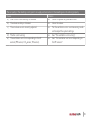
2.6. Accessories
Accessories
Item no.
Type
RF-VI
95970200
95970003
95970204
95970002
95970201
95970203
95970202
TRANSMITTER
RFTTRANSMITTER W
RFT-AUTO CO2
HRS-3I C
Description
Wireless RF-VI remote with LED signals, three
modes and timer function
Wireless RF control switch with three settings and
a timer function (White)
RF control switch with two positions, automatic
and timer functions
Conventional wired switch with three settings
RF-CO2
230 V RF CO2-sensor
RF-RH [BAT]
RF-RH battery-powered sensor
RF-PIR
RF-PIR battery-powered presence sensor
19
3. Operation
3.1. Control options
The ventilation unit has several pre-programmed modes.
A number of control switches are available for actively
setting the correct mode/ventilation capacity:
●
Wireless RF-VI remote control with LED indicator for
status and ventilation functions
●
Wireless RF control switch with three settings and a
timer function
●
Wireless RF control switch with two settings, an
automatic setting and a timer function
●
Conventional wired switch with three settings
●
A combination of the above options.
For pairing or unpairing a wireless RF remote control
with/from the unit, consult Pairing and unpairing RF
remote controls on page 30
Note
Do not attach wireless control switches to metal
surfaces. This can interfere with the wireless control
switch or cause it to stop working entirely.
Note
The wireless control switches have a range of 100
metres in free space (no obstacles). The distance at
which the switch can function properly is reduced
depending on the obstacles interfering with the
signal.
Note
When using a wireless control switch in the bathroom,
it should not be located in zone 0 (floor of the shower
base) or zone 1 (up to 2.5 metres above the shower
base) due to the effects of moisture.
20
ä Caution!
If the fan runs at high speed when low speed is
selected or at low speed when high speed or timer
mode is selected, the ventilation unit is faulty.
See Faults on page 38 for possible causes of problems
and potential solutions.
21
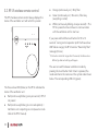
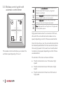
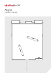
3.2. RF-VI wireless remote control
This RF-VI wireless remote control always displays the
status of the ventilation unit with which it is paired.
●
Orange (continuously on) = Dirty filter
●
Green (continuously on) = No errors, filter okay
(everything in order)
●
White (continuously blinking once per second) = The
RF-VI is paired but has not been in communication
with the ventilation unit for one hour
RF - VI
If you press and hold the touch button for 10 to 12
seconds * during normal operation (until the three-colour
LED flashes orange), the RF-VI sends a "Reset dirty filter"
message (3 times).
*
If the button is held for longer than 12 seconds, the three-colour
LED will go dark and nothing will happen.
The user can switch between ventilation modes by
pressing the touch button. Each time it is pressed, the
mode switches to the next one in the cyclical order shown
below. The corresponding LED is lit (green).
The three-colour LED (Status) on the RF-VI indicates the
status of the ventilation unit.
●
Red (continuously blinking once per second) = RF-VI
not paired
●
Red (continuously blinking in error code pattern) =
Ventilation unit is reporting an error (see error code
table in the RF-VI manual)
22
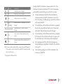
LED
Activity
On
On
Ventilation unit in Mode 1
On
Ventilation unit in Auto Mode
On/
blinking
Ventilation unit is in Mode 3 or Timer
Above signals off
On
On
Meaning
Ventilation unit in Mode 2
●
If the touch button is held for 5 seconds during
normal operation (the RF-VI has been on for more
than 2 minutes), all LEDs will go out and the interface
will be switched off.
Mode *
Ventilation unit is in Not at Home
Mode
●
If the interface is off and the touch button is pressed
briefly, the active LEDs will light up for 10 seconds,
after which the interface will switch off again.
Frost control of the ventilation unit is
active
●
If the interface is off and the touch button is pressed
for 5 seconds, the interface will switch on again and
the ventilation unit information will be displayed.
●
Error messages and the dirty filter message are
always displayed, regardless of whether the interface
is on or off.
●
The interface setting (on or off) is recorded in the
memory of the RF-VI.
Bypass control of the ventilation unit is
active **
* When timer mode is selected, the corresponding LED blinks for
10 seconds in a particular pattern (see RF-VI manual) and then
stay lit continuously
**
Usually, the RF-VI interface is always switched on. The
interface can also be switched off for normal operation,
and all LEDs automatically go out after this is done.
Only applies to Advance Plus
23
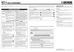
3.3. Wireless control switch with timer
Level 1, low speed; when one person is present during
the day or night, or when no-one is present.
Level 2, medium speed; during the day or night when
more than one person is present.
Level 3, high speed; during cooking, showering or
bathing, or when a lot of people are present.
Timer; high speed for switching the unit to high speed
for an adjustable period.
This wireless RF control switch can easily be placed in any
room by applying double-sided tape to the back of the
switch.
High speed remains active for a maximum of 24 hours,
after which the unit switches back to medium or low
speed, depending on which of these was selected last.
Once the timer has run out, the unit switches back to the
last selected speed before the timer was started, unless
that was high speed. In that case the unit switches back
to medium or low speed, depending on which of these
was selected last.
The duration of the timer can be set as follows:
This wireless control switch allows you to select the
ventilation speed (capacity) of the unit:
24
●
Press the timer button once: 10 minutes at high
speed
●
Press the timer button twice: 20 minutes at high
speed
●
Press the timer button three times: 30 minutes at
high speed.
The timer can be stopped at any time by pressing the
button for low, medium or high mode.
25
3.4. Wireless control switch with
automatic control/timer
Auto setting, automatic mode; sensor-based control
(CO2, RV and/or PIR). The capacity is regulated
between low and high.
Level 1, low speed; when one person is present during
the day or night, or when no-one is present.
Level 3, high speed; during cooking, showering or
bathing, or when a lot of people are present.
Timer; high speed for switching the unit to high speed
for an adjustable period.
High speed remains active for a maximum of 24 hours,
after which the unit switches back to medium or low
speed, depending on which of these was selected last.
This wireless control switch allows you to select the
ventilation speed (capacity) of the unit:
Once the timer has run out, the unit switches back to the
last selected speed before the timer was started, unless
that was high speed. In that case the unit switches back
to medium or low speed, depending on which of these
was selected last.
The duration of the timer can be set as follows:
26
●
Press the timer button once: 10 minutes at high
speed
●
Press the timer button twice: 20 minutes at high
speed
●
Press the timer button three times: 30 minutes at
high speed.
The timer can be stopped at any time by pressing the
button for low speed, high speed or automatic mode.
Note
If sensors have been paired with the ventilation unit,
low speed or high speed will remain active for a
maximum of one day, after which automatic mode
will be activated.
27
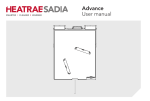
3.5. Wired three-position switch
This control switch is connected directly using connecting
wires. The wired control switch can be combined with
one or more wireless control switches.
1
2
3
Level 1, low speed; when one person is present during
the day or night, or when no-one is present.
Level 2, medium speed; during the day or night when
more than one person is present.
Level 3, high speed; during cooking, showering or
bathing, or when a lot of people are present.
High speed remains active for a maximum of 24 hours,
after which the unit switches back to medium or low
speed, depending on which of these was selected last.
Note
Using the wired three-position switch, the unit can be put
into three different ventilation modes (capacities) by
turning the switch:
28
If the wired control switch is combined with a wireless
control switch, there is a risk that the ventilation unit
may be set to high by the wired switch and then to
low by the wireless switch. In this case, the wired
switch will indicate high speed when the ventilation
unit is actually running at low speed.
In order to re-activate the wired control switch in this
situation, you should first switch it to another speed.
Note
For ventilation units with which sensors have been
paired (CO2, RV and/or PIR), Mode 2 operates as an
automatic mode.
Note
If sensors have been paired with the ventilation unit,
low speed or high speed will remain active for a
maximum of one day, after which automatic mode
will be activated.
29
3.6. Pairing and unpairing RF remote
controls
3.6.1. Pairing an RF-VI remote control
Consult the manual supplied with the RF-VI for
information on pairing this wireless remote control.
3.6.2. Pairing RF remote controls
3.6.3. Unpairing an RF-VI remote control
Consult the manual supplied with the RF-VI for
information on unpairing this wireless remote control.
3.6.4. Unpairing RF remote controls
It is best to unpair wireless RF remote controls from a
ventilation unit in the vicinity of that unit.
a)
Disconnect power to the ventilation unit.
It is best to pair wireless switches with a ventilation unit in
the vicinity of that unit.
b)
Wait for at least 15 seconds.
c)
Restore power to the ventilation unit.
a)
Disconnect power to the ventilation unit.
d)
b)
Wait for at least 15 seconds.
c)
Restore power to the ventilation unit.
Within two minutes after powering up the ventilation
unit, press the four buttons on the control switch at
the same time.
d)
Within two minutes after powering up the ventilation
unit, press two diagonally opposite buttons on the
RF control switch at the same time.
The control switch is paired, and the ventilation unit
briefly changes the motor speed to confirm the pairing.
The ventilation unit is now ready to be operated using
the wireless control switch.
30
The ventilation unit will now no longer respond to the
wireless control switch(es). Unpairing one control switch
automatically unpairs all control switches, controls and RF
sensors.
Note
If several wireless switches, controls and/or RF
sensors were paired with the unit in question, they
must be individually re-paired after being unpaired.
3.7. Pairing and unpairing RF sensors
3.7.1. Pairing RF sensors
Pair wireless sensors with the ventilation unit as follows:
a)
Disconnect power to the ventilation unit.
b)
Wait for at least 15 seconds.
c)
Restore power to the ventilation unit.
d)
Ensure that a pairing message is sent from the RF
sensor within two minutes after power to the
ventilation unit is switched on. For more information,
consult the documentation for the relevant sensor.
Note
If several wireless switches, controls and/or RF
sensors were paired with the unit in question, they
must be individually re-paired after being unpaired.
The RF sensor is paired, and the ventilation unit briefly
changes the motor speed to confirm the pairing. The
ventilation unit is now ready to respond to the signals of
the wireless sensor.
3.7.2. Unpairing RF sensors
RF sensors can only be unpaired at the same time as an
RF remote control. For more information, see the
procedure Unpairing an RF-VI remote control or
Unpairing RF remote controls on page 30.
31
4. Inspection and maintenance
Proper functioning of the ventilation unit, its effectiveness
and its service life can only be assured if the system is
inspected and maintained in accordance with the
provisions below. These provisions are based on normal
operating conditions.
ä Caution!
If the ventilation system is being used under harsh
operating conditions or in a very dirty environment,
extra maintenance may be required.
4.1. Inspection and maintenance
schedule
Inspection schedule Advance and Advance Plus
Check for unusual noises coming from the
ventilation unit, air valves and ducts
Filter G3
Filter G4
Check for soiling
Filter F7
Ventilation unit
Check for soiling and condensation leakage
Motor module
Check for soiling/imbalance
Check functioning and for soiling
Bypass valve *
Air valves
Check for soiling
Ducts
Check for soiling
Noise
32
User
Installer
6 months
1 year
1 week
9 months
6 months
6 months
—
—
3 months
—
—
1 year
1 year
1 year
1 year
1 year
1 year
4 years
*
Only applies to Advance Plus
Maintenance schedule for Advance and Advance Plus
Filter G3
Filter G4
Filter F7
Ventilation unit
Motor module
Bypass valve*
Air valves
Ducts
Battery for RF remote
control
*
Only applies to Advance Plus
Clean (first 3 months)
Replace (with G4 or F7)
Clean
Replace
Clean
Replace
Clean outside
Clean condensate hose
Clean
Clean
Clean
Clean
Replace
User
Installer
1 week
Where necessary
3 months
9 months
18 months
6 months
12 months
3 months
—
—
—
3 months
—
Where necessary
Where necessary
Where necessary
Where necessary
Where necessary
1 year
1 year
4 years
1 year
1 year
8 years
Where necessary
Where necessary
Note
It is not possible to remove the heat exchanger from
the ventilation unit. Under normal conditions, and if
the correct filters are used, it should not be necessary
to clean the heat exchanger.
33
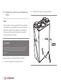
4.2. Inspecting, cleaning and replacing
filters
Note
The ventilation unit comes with G3 filters as standard.
These filters are very suitable for use as "construction
dust filters" after initial completion of the dwelling.
After around three months, these filters should be
replaced with G4 or F7 filters.
ä Caution!
G4 and F7 filters can be cleaned once, after which
they must be replaced at the next maintenance
interval.
Inspect and clean or replace the filters as follows:
a)
34
Disconnect power to the ventilation unit.
b)
Pull both filter caps out of the front panel.
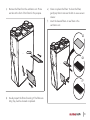
c)
Remove the filters from the ventilation unit. There
are tabs at the front of the filters for this purpose.
e)
Clean or replace the filters. To clean the filters,
gently tap them to remove the dirt or use a vacuum
cleaner.
f)
Insert the cleaned filters or new filters in the
ventilation unit.
G3
G4
F7
d)
Visually inspect the filters for soiling. If the filters are
dirty, they must be cleaned or replaced.
35
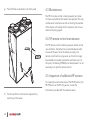
g)
Put both filter covers back in the front panel.
4.3. Maintenance
The RF-VI remote control is mains powered, so it does
not have any batteries that need to be replaced. The only
maintenance to be done consists of cleaning the outside
of the device with a damp cloth if necessary. Do not use
chemical cleaning agents.
4.4. RF remote control maintenance
The RF remote control is battery powered. Under normal
use conditions, the battery has an estimated service life
of around 10 years. Once the battery is empty, the
remote control will no longer work, and it will no longer
be possible to manually operate the ventilation unit. At
this point, the battery (CR2032) must be replaced. It is not
necessary to re-pair the remote control.
4.5. Inspection of additional RF sensors
For inspection and maintenance of the RF-RH sensor, the
RF-PIR sensor or the RF CO2 sensor, consult the
information provided with the relevant sensor.
h)
36
Put the ventilation unit back into operation by
switching on the power.
4.6. Inspecting and cleaning air valves
Check the air valves regularly (around once every three
months) for soiling. If the air valves are dirty, they must be
cleaned.
ä Caution!
When removing or replacing air valves and grilles,
watch out for protruding duct sections. These can be
very sharp.
ä Caution!
When cleaning, do not adjust the air valve settings,
and replace the valves in their original ducts.
37
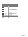
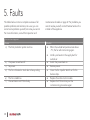
5. Faults
The tables below contain a complete overview of all
possible problems and solutions. As a user, you can
correct some problems yourself, but some you cannot.
For more information, consult the Inspection and
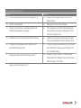
The fan has stopped
Cause
a) The frost protection system is active.
maintenance schedule on page 32. For problems you
cannot resolve yourself, contact Heatrae Sadia or the
installer of the appliance.
Solution
●
When the outside temperature rises above
-1°C, the fan will start running again.
●
b)
c)
d)
The power is switched off.
No power.
The fan is blocked or stuck due to heavy soiling.
●
●
●
e)
f)
The fan is defective.
The ventilation unit PCB is faulty.
●
●
38
Install a pre-heater in the supply duct for
outside air.
Switch the power back on.
Restore power.
Clean the fan impeller. Watch out for the
balance clips.
Replace the entire motor module.
Replace the PCB and carry out the
commissioning procedure again.
The ventilation unit is noisy
Cause
a) The fan is blocked or stuck due to heavy soiling.
b)
c)
The fan is imbalanced.
The unit is mounted on a wall/ceiling/floor with
insufficient load-bearing capacity.
d)
The ducts are not correctly connected to the unit.
e)
The second condensate drain is open and not
connected (hissing sound).
f)
The bypass valve is blocked (rattling noise). (*)
*
Solution
●
Clean the fan impeller. Watch out for the
balance clips.
●
Replace the entire motor module.
●
If the ventilation unit cannot be relocated, try
using vibration dampers to decouple it from
the wall, ceiling or floor.
●
Check the connections and ensure that fixed
ducts are clamped to the wall, ceiling or floor.
●
Close the second condensate drain by folding
back the tab with the plug and clicking it into
the condensate drain.
●
Inspect the valve. Clean it if it has become
blocked with dirt. Replace the valve if there is a
different cause of the fault.
Applies exclusively to Advance Plus
39
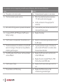
The ventilation unit is not responding to the RF sensors (PIR sensor, 230 V CO2 sensor, RV sensor)
Cause
a) The system is not in Auto mode.
b) The frost protection system is active.
Solution
●
If desired, place the system in Auto mode.
●
When the outside temperature rises above
-1°C, the fan will start running again.
●
c)
With a 230 V RF-CO2 sensor: no power to the sensor.
●
d)
If using an RF-RH or RF-PIR sensor: the RF sensor
battery is empty.
●
e)
The RF sensor is not paired with the ventilation unit.
●
f)
The distance between the ventilation unit and the RF
sensor is too large, or there are too many obstacles
interfering with the signal.
The OEM codes of the RF sensor and the ventilation
unit are different.
●
g)
●
●
h)
The RF sensor is faulty.
●
i)
The ventilation unit PCB is faulty.
●
40
Install a pre-heater in the supply duct for
outside air.
Check whether power has been switched off or
interrupted. Restore power.
Replace the battery.
Restart the commissioning procedure and pair
the RF sensor.
Try pairing the devices again. If this does not
work, move the RF sensor to a location where
there are fewer obstacles.
Replace the RF sensor with one that has the
correct OEM code.
Replace the motor module PCB with a PCB
that has the correct OEM code.
Replace the RF sensor and re-pair it with the
unit.
Replace the PCB and carry out the
commissioning procedure again.
The ventilation unit is not responding to the RF remote controls
Cause
Solution
a) The frost protection system is active.
●
When the outside temperature rises above
-1°C, the fan will start running again.
●
b)
c)
The battery of the RF remote control is empty.
The RF remote control is not paired with the
ventilation unit.
●
●
d)
The distance between the ventilation unit and the RF
remote control is too large or there are too many
obstacles interfering with the signal.
●
e)
The OEM codes of the RF remote control and the
ventilation unit are different.
●
●
f)
The ventilation unit PCB is faulty.
●
Install a pre-heater in the supply duct for
outside air.
Replace the battery.
Restart the commissioning procedure and pair
the RF remote control.
Try pairing the devices again. If this does not
work, move the RF remote control to a location
where there are fewer obstacles to interfere
with it.
Replace the RF remote control with one that
has the correct OEM code.
Replace the motor module PCB with a PCB
that has the correct OEM code.
Replace the PCB and carry out the
commissioning procedure again.
41
The fan runs at high speed when low speed is selected and at low speed when high speed or timer mode is selected
Cause
Solution
a) One of the RF sensors has a problem.
●
See table "The ventilation unit is not
responding to the RF sensors".
b) One of the ventilation unit's internal temperature
●
Replace the faulty temperature sensor.
sensors is faulty.
The fan suddenly starts running much faster or slower (for no apparent reason)
Cause
Solution
a) After using the timer function, the ventilation unit
●
If desired, change the system setting.
switches back to the last selected speed before the
timer was started.
b) If sensors have been paired with the ventilation unit, it
●
If desired, change the system setting.
switches back to automatic mode 24 hours after
being set to low or high speed.
c) The RF remote control from a neighbouring property
●
Disconnect power to the ventilation unit for 15
is paired with this ventilation unit.
seconds. Unpair any paired RF remote controls
(and any RF sensors) and re-pair the remote
controls (and any RF sensors).
42
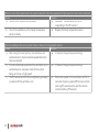
The ventilation unit is not responding to the three-position switch
Cause
Solution
a) The frost protection system is active.
●
When the outside temperature rises above
-1°C, the fan will start running again.
●
b)
c)
d)
e)
The power is switched off.
No power.
The switch wires of the three-position switch are
connected incorrectly.
The ventilation unit PCB is faulty.
The ventilation unit is leaking water
Cause
a) The condensate drain is not connected.
b) The condensate drain is blocked.
c)
The second condensate drain is open and not
connected (hissing sound).
●
●
●
●
Install a pre-heater in the supply duct for
outside air.
Switch the power back on.
Restore power.
Connect the switch wires correctly (see wiring
diagram).
Replace the PCB and carry out the
commissioning procedure again.
Solution
●
Connect one of the two condensate drains.
●
Unblock the condensate drain and try to
identify the cause of the problem.
●
Close the second condensate drain by folding
back the tab with the plug and clicking it into
the condensate drain.
43
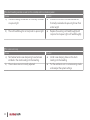
The ducts leading outside are wet (on the outside) and/or are leaking water
Cause
Solution
a) The ducts leading outside are not thermally insulated
●
Ensure that the ducts that lead outside are
or vapour-tight.
thermally insulated and vapour-tight over their
entire length.
b) The roof feedthrough is not rainproof or vapour-tight.
●
Replace the existing roof feedthrough(s) with
rainproof and vapour-tight roof feedthrough(s).
The valves are noisy
Cause
a) No Heatrae Sadia noise dampening hose has been
installed in the ducts leading into the dwelling.
b) The air valves are not correctly adjusted.
44
Solution
●
Install noise damping hoses on the ducts
leading into the dwelling.
●
Put the ventilation unit in commissioning mode
and readjust the system settings.
The air quality in the dwelling is not good / air supply and extraction in the dwelling are not working properly
Cause
Solution
a) One or both filters are dirty or blocked.
●
Clean or replace dirty/blocked filters.
b) The valves are dirty or blocked.
●
Clean the valves.
c) The air valves are not correctly adjusted.
●
Put the ventilation unit in commissioning mode
and readjust the system settings.
d) The fan is not running.
●
See "The ventilator is not running".
e) The ventilation unit is not responding to the RF
●
See "The ventilation unit is not responding to
sensors (PIR sensor, CO2 sensor, RV sensor).
the RF sensors".
45
Cold air is being supplied to the dwelling
Cause
a) The filter in the extraction outlet is blocked.
b) The air valves are not correctly adjusted.
c)
d)
The bypass valve is in bypass mode when it should
not be. (*)
One of the temperature sensors is faulty.
Solution
●
Clean or replace the filter in the air outlet.
●
Put the ventilation unit in commissioning mode
and readjust the system settings.
●
Clean the bypass valve if it is dirty.
●
●
●
*
46
Only applies to Advance Plus
Replace the entire bypass valve if it is
defective. (*)
If the supply air temperature sensor is faulty,
replace the wiring harness with the
temperature sensor in the motor module.
If the exhaust air temperature sensor is faulty,
replace the entire bypass module. (*)
6. Warranty
The warranty is valid for 2 years after the installation date.
Disclaimer
This warranty does not apply to:
●
Disassembly and assembly costs.
●
Faults which are caused by incorrect treatment.
●
Negligence or accident.
●
Faults that have been caused by repairs by third
parties without authorisation from Heatrae Sadia.
If the appliance does not function correctly or develops a
fault please contact Heatrae Sadia immediately.
Ensure that only genuine spares are used for repairs.
47
7. Declarations
Inbouwverklaring | Déclaration d'incorporation |
Einbauerklärung | Declaration of incorporation
Heatrae Sadia
Hurricane Way
Norwich NR6 6EA
United Kingdom
Verklaart dat het product | Déclare que le produit |
Erklärt dass das Produkt | Declares that the product:
48
-
Ventilation unit with heat recovery
Advance – 95060001
-
Ventilation unit with heat recovery
Advance Plus – 95060007
Must be considered as a partly completed machine and may not
be put into service until the end machine into which it will be
integrated has been declared as being in conformity with the
provisions of the Machinery Directive 2006/42/EC |
Doit être considéré comme une machine non terminée et ne peut
pas être mise en service tant que la machine finale, installée à son
emplacement définitif, n'est pas déclarée conforme aux
dispositions des directives relatives aux machines 2006/42/CE |
Voldoet aan de bepalingen gesteld in de richtlijnen |
Répond aux exigences des directives |
Entspricht den Anforderungen in den Richtlinien |
Complies with the requirements stated in the directives:
-
Low Voltage Directive 2006/95/EC
-
Electromagnetic Compatibility (EMC) Directive
2004/108/EG
-
Directive 2011/65/EU (RoHS)
Voldoet aan de geharmoniseerde Europese normen |
Répond aux normes Européennes harmonisées |
Entspricht den harmonisierten europäischen Normen |
Complies with the harmonized European standard:
●
EN 60335-1:2012 | EN 60335-2-80:2003/A1:2004
EN 60335-2-80:2003/A2:2009
●
EN 60730-1:2012
●
EN 55014-1:2007 | EN 55014-1:2007/C1:2009
EN 55014-1:2007/A1:2009 | EN 55014-1:2007/A2:2010
EN 55014-2:1998 | EN 55014-2:1998/C1:1998
EN 55014-2:1998/A1:2002 | EN 55014-2:1998/IS1:2007
EN 55014-2:1998/A2:2008
●
EN 61000-3-2:2006/A1:2009 | EN 61000-3-2:2006/
A2:2009
EN 61000-3-3:2013 | EN 61000-6-1:2007
EN 61000-6-3:2007/A1:2011 | EN 61000-6-3:2007/AC:
2012
Norwich, December 1, 2014.
49
HEATRAE SADIA HEATING
Hurricane Way, Norwich NR6 6EA
www.heatraesadia.com
SERVICE
01603 420100
EMAIL
[email protected]
HS | 36006181 issue 03
01-00112-001 | ID 2015-01-28-1626