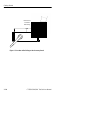
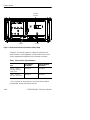
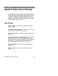
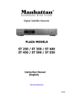
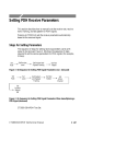
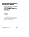
1
Getting Started
This section provides a description of the CTS850, a list of standard
and optional accessories, and explains how to operate the CTS850
for the first time.
Product Description
The Tektronix CTS850 SDH/PDH Test Set is a rugged, portable test
set designed for installing and maintaining telecommunications
networks. The CTS850 is an SDH analyzer that combines bit error
rate test capabilities with overhead testing, payload mapping, and
demapping in one unit. The CTS850 features the following
capabilities:
H STM-0E, STM-0, STM-1E, STM-1, STM-4, 2 Mb/s, 8 Mb/s,
34 Mb/s, and 140 Mb/s transmit and receive
H Optical interface available at 1310 nm and 1550 nm
H Bit Error Rate testing
H BER test of VC4 4c concatenated payloads at 622 Mbit/s
H 45 Mbit/s mapping and demapping into SDH (optional)
H BIP error monitoring and analysis
H 2, 8, 34 and 140 Mbit/s PDH multiplexing/demultiplexing
(MUX/DEMUX) with N/Mx64 kbit/s testing
H Payload mapping and demapping
H Jitter generation and analysis
H Wander generation and measurement (Real Time Wander
Analyst PC application software for TDEV/MTIE)
H Unique timing quality measurement
H Pointer generation, including sequences and analysis
H Alarm generation and analysis
CTS850 SDH/PDH Test Set User Manual
1 1
Getting Started
H TU error monitoring and analysis
H Performance monitoring per G.821, G.826, M.2100 and
M.2101.1 on all layers simultaneously
H Automatic Protection Switching (APS) testing
H DCC and user channel access
H Programmable via IEEE 488.2 and RS-232
The CTS850 meets the needs of the craftsperson and the network
engineer. The CTS850 meets the requirements of those working in
network installation and maintenance by providing the capability to
perform:
H Network integrity testing
H In-service performance monitoring
H Stimulus and response testing
H Stress testing
H Overhead testing
H Automated jitter conformance testing
H G.821, G.826, M.2100 and M.2101.1 performance measurement
Accessories
Some accessories are included with the CTS850 SDH/PDH Test Set.
If you wish to purchase optional accessories or additional standard
accessories, see a Tektronix products catalog or contact your local
Tektronix field representative.
Standard Accessories
H CTS850 SDH/PDH Test Set User Manual, Tektronix part number
070-9988-XX
H CTS850 SDH/PDH Test Set Reference Manual on CD ROM,
Tektronix part number 063 3013 XX
1 2
CTS850 SDH/PDH Test Set User Manual
Getting Started
H CTS 850 SDH/PDH Test Set Programmer Manual, Tektronix part
number 070-9990-XX
H Instrument Front Cover, Tektronix part number 200-3232-XX
H 75
loopback BNC cable, Tektronix part number 012-1338-XX
H Pouch (to hold printer, user manual, etc.) Tektronix part number
016-1266-XX
Optional Accessories
H CTS 850 SDH Test Set Service Manual (Tektronix part number
070-9991-XX)
H Electrical STS 0E/1E and STM 1 Plug in (Standard)
H FC, SC or ST Optical Connectors
H 1.6/1.5 connectors for all 75 Ohm BNC front panel connectors
H 2,8,34, 140 Mbit/s, VC 12, TU 3 Add/Drop Test
H Universal European: 220 V, 50 Hz power cord
H UK: 240 V, 50 Hz power cord
H Australian: 240 V, 50 Hz power cord
H North American: 240 V, 60 Hz power cord
H Switzerland: 220 V, 50 Hz
H Hard Transit Case, Tektronix part number 016-1157-XX
H Soft Carrying Bag, Tektronix part number 016-1158-XX
H Optical Connector Kit, Tektronix part number 020-1885-XX
CTS850 SDH/PDH Test Set User Manual
1 3
Getting Started
Navigation CTS 850 Paper basedManual & CD ROM
The following table shows you where to quickly find the section that
answers your particular test & measurement questions.
In order to get you going as fast as possible with the CTS 850 test
set, the paper based user manual focuses solely on Getting Started
information.
Everything else appears in the reference manual on CD ROM,
including all information contained in the paper based user manual.
Table 1 1:Where to Find Information in this User Manual
Look in this part of the
manual:
If you want to know how to:
Use the basic functions of the test set, including
Controls, indicators, connectors; Elements of
front panel display; Menu structure; Online help;
Connecting signals; Selection and editing of
choices; Disk drive operation
Functional Overview,
Chapter 2
Tutorial
Tutorial, Chapter 2
Setup and use the test set for network and
equipment test applications, including
* Network continuity checking
* Transmission signal quality testing
* Fault tolerance testing
* Performance monitoring
* Jitter and wander testing
* Video timing quality testing
Basic Test Procedures,
Chapter 3
(paper basedand
reference manual on CD)
(paper basedand
reference manual on CD)
Set TX (SDH, PDH)
(reference manual on CDonly)
Set transmit rate; specify the AU under test; set
the payload mapping and content; and set the
overhead bytes for SDH signals
Setting SDH Transmit
Parameters, Chapter 3
Set transmit rate, transmit clock, line clock offset, Setting PDH Transmit
payload, framing, test pattern, active channel and Parameters, Chapter 3
background pattern for PDH signals
1 4
CTS850 SDH/PDH Test Set User Manual
Getting Started
Table 1 1:Where to Find Information in this User Manual (Cont.)
If you want to know how to:
Set RX (SDH, PDH)
(reference manual on CDonly)
Look in this part of the
manual:
Set receive line rate; specify the AU under test;
set payload mapping and content; check
received optical signal power; view overhead
bytes for SDH
Setting SDH Receive
Parameters, Chapter 3
Set the receive rate, receive level, framing and
test pattern for PDH signals
Setting PDH Receive
Parameters, Chapter 3
Jitter/Wander Set TX/RX, Work with Test
Setups, Calibrate
(paper basedand reference manual on CD)
Setting Jitter/Wander
Parameters, Chapter 3
Set & Test Alarms, Errors, Pointers, Timing,
APS
(reference manual on CDonly)
Generate error conditions, set alarms, and
simulate network failures
Setting Alarms and Inserting
Errors, Chapter 3
Generate Automatic Protection Switching (APS)
commands and view the network response
Testing Automatic
Protection Switching,
Chapter 3
Set the duration for a test, the resolution of test
history, start and stop a test
Setting Test Control
Parameters, Chapter 3
Save and recall instrument setups; Create and
run pass/fail tests
Working with Test Setups,
Chapter 3
Change date and time settings, printer settings,
GPIB, RS 232parameters. Run a self test
Changing Instrument
Settings, Chapter 3
View, Print, Save & Recall Measurements
(reference manual on CDonly)
Monitor input signal for alarms, errors and
Checking Signal Status,
failures, indicating current signal status, history of Chapter 3
signal status
View, save, recall, and print test results
CTS850 SDH/PDH Test Set User Manual
Viewing Results, Chapter 3
1 5
Getting Started
Table 1 1:Where to Find Information in this User Manual (Cont.)
Look in this part of the
manual:
If you want to know how to:
Appendices
(reference manual on CDonly)
Review available menu choices; Navigate menus Menu Maps, Appendix A
1 6
Interpret Status & Error Messages
Status & Error Messages,
Appendix B
Review Default Factory Settings
Default Factory Settings,
Appendix C
Check all Specifications
Specifications, Appendix D
Verify the test set functions properly
Incoming Inspection Test,
Appendix E
Check examples of instrument setups, test
results and pass/fail tests that can be loaded into
the test set
Example Disk Contents,
Appendix F
Explain Rear PanelConnectors
Rear PanelConnectors,
Appendix G
Change Optical Port Connectors
Changing Optical Port
Connectors, Appendix H
Pack for Shipment
Packing for Shipment,
Appendix I
Review telecommunications
technology used by the test set
Telecommunications
Technology, Appendix J
Look up word meanings in Glossary; review
ITU Tstandards used by the test set
Glossary and ITU T
Standards
CTS850 SDH/PDH Test Set User Manual
Getting Started
First Time Operation
This section describes how to set up the CTS850 for the first time.
Installing the Accessory Pouch
The CTS850 ships with an accessory pouch that mounts on top of the
instrument. The pouch is not installed at the factory. To install the
accessory pouch:
1. Place the CTS850 on a table or work bench with the front facing
toward you.
2. Center the pouch plate and insert the rear edge of the plate in the
space between the cabinet top and the rear panel trim (see part A
of Figure 1 1).
3. Move the pouch sideways as necessary to line up the key slots in
the pouch plate with the keys on the rear panel (the plate is
centered when it is aligned) and push the plate all the way in (see
part B of Figure 1 1).
4. While keeping the pouch plate pushed under the rear panel trim,
reach under the pouch plate and carefully remove the backing
from the Velcro strip to expose the adhesive on the Velcro strip.
The Velcro should remain attached to the pouch plate.
5. Grasp the pouch plate assembly with both hands near the front of
the assembly.
CTS850 SDH/PDH Test Set User Manual
1 7
Getting Started
Rear Panel Trim Gap
Pouch
Plate
Pouch Plate
Velcro Strip
Rear
Panel
Trim
(Top View)
A. Push the pouch plate into the rear panel trim gap.
Key Slots Under
Rear Panel Trim
B. Center the pouch plate to align with key slot under the rear panel trim.
Figure 1 1:Installing the Accessory Pouch
1 8
CTS850 SDH/PDH Test Set User Manual
Getting Started
CAUTION. In the next step, use only enough force to clear the front
panel trim with the plate front edge. Excessive force will cause a
permanent bow in the plate.
6. Push back on the pouch plate and press down with the heels of
your hands to bow the plate enough to slide the front of the plate
into the space between the cabinet top and the front panel trim
(see Figure 1 2).
7. Move the front of the pouch as needed to line up the slots in the
plate with the keys on the front panel.
8. Release the pressure on the plate to allow it to return to its normal
flat shape.
9. Press down firmly to secure the Velcro strip to the top of the
cabinet top.
Velcro Strip
Figure 1 2:Inserting the Pouch Under the Front Panel Trim
CAUTION. Do not use the D-ring (see Figure 1 3) on the pouch plate
to lift the CTS850. Using the D-ring to lift the CTS850 can pull the
accessory pouch off the CTS850, resulting in damage to the
CTS850.The purpose of the D ring is to provide extra support when
the test set is placed in an upright position.
CTS850 SDH/PDH Test Set User Manual
1 9
Getting Started
DO NOT LIFT
Instrument
With D-Ring
Figure 1 3:Location of the D-Ring on the Accessory Pouch
1 10
CTS850 SDH/PDH Test Set User Manual
Getting Started
Setting Up the CTS850
Before you use the CTS850, ensure that it is properly set up and
powered on.
To properly set up the CTS850, do the following:
1. Be sure that the environment in which you will operate the
CTS850 is within instrument specifications. Specifications for
temperature, relative humidity, altitude, vibrations, and emissions
are included in the Appendix.
2. Leave space around the CTS850 for cooling. Verify that the air
intake and exhaust holes on the sides of the cabinet (where the
fan operates) are free of any airflow obstructions. Leave at least
5 cm (2 in) free on each side.
WARNING. To avoid electrical shock, be sure that the power cord is
disconnected before checking the fuse.
3. Check the fuse to be sure it is the proper type and rating (see
Figure 1 4). The CTS850 works with one of two fuses,
depending on the AC supply. Each fuse requires its own cap (see
Table 1 2). The CTS850 is shipped with the UL-approved fuse
installed.
CTS850 SDH/PDH Test Set User Manual
1 11
Getting Started
AC Power
Connector
Ground
AC Fuse
Figure 1 4:Rear-Panel Controls and Connectors Used in Setup
See page 2 4 in the next chapter for a labeling of what each rear
panel connector is. See the appendix on Rear Panel Connections for
a more comprehensive explanation of the rear panel connectors.
Table 1 2:Fuse and Fuse Cap Part Numbers
Fuse Tektronix
Part Number
Fuse Cap Tektronix
Part Number
0.25 in × 1.25 in
(UL 198.6, 3AG): 8 A
FAST, 250 V
159-0046-XX
200-2264-XX
5 mm × 20 mm *
(IEC 127): 6.3 A, 250 V
159-0381-XX
200-2265-XX
Fuse
* If it is necessary to use the extra 5 mm x 20 mm fuse included in
the fuseholder, the fuse cap must be removed.
1 12
CTS850 SDH/PDH Test Set User Manual
Getting Started
4. Check that you have the proper electrical connections. The
CTS850 power requirements are listed in Table 1 3.
Table 1 3:Power Requirements
Voltage Range
Frequency Range
90 132V
50/60 Hz
180 250V
50/60 Hz
100 132V
400 Hz
5. Connect the proper power cord from the rear-panel power
connector (see Figure 1 4) to the power system.
Turning On the CTS850
To properly turn on the CTS850:
1. Press the front panel ON/STBY button (see figure 1 5).
The ON/STBY button controls power to all instrument circuits.
The CTS 850 performs an internal self test each time it is turned
on. When turned on, it displays a screen that states whether or not
it passed the self test. (If the self test passes, the status display
screen is removed after a few seconds.)
2. Check the self test results.
If the self test fails, contact your local Tektronix Service Center
for assistance.
CTS850 SDH/PDH Test Set User Manual
1 13
Getting Started
CTS850 SDH Test Set
ON/STBY
Button
Figure 1 5:ON/STBY Button
Turning Off the CTS850
Press the ON/STBY button to turn off the CTS850.
1 14
CTS850 SDH/PDH Test Set User Manual