1
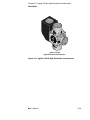
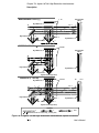
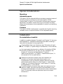
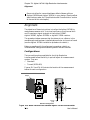
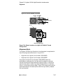
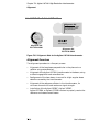
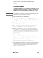
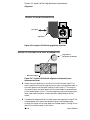
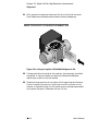
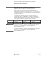
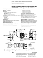
7H
Agilent 10716A High-Resolution
Interferometer
Chapter 7H Agilent 10716A High-Resolution Interferometer
Description
Description
The Agilent 10716A High Resolution Interferometer (see Figure 7H-1)
offers twice the resolution of conventional plane mirror interferometers
and has the same excellent thermal characteristics as the
Agilent 10706B interferometer (typically, only 0.04 micron of drift per
degree C). Measurement drift is typically 1/12 of that exhibited by a
conventional plane mirror interferometer. These features result in
improved accuracy, repeatability, and positioning capability.
Although the Agilent 10716A interferometer is larger than the
conventional plane mirror interferometer and the slew rate is halved,
the finer resolution of this optic allows laser measurement system
measurement resolution of 2.5 nanometers (0.1 microinch) with most
Agilent laser electronics.
The Agilent 10716A interferometer can be used in the same
applications as other Agilent plane mirror interferometers, but with
different alignment techniques. A turned configuration
(Agilent 10716A-001) is available to turn the beam 90 degrees, thereby
eliminating the need for a beam bender. Like other plane mirror
interferometers the Agilent 10716A uses plane mirror reflectors such
as the Agilent 10724A Plane Mirror Reflector or a suitable
user-supplied plane mirror.
Figure 7H-2 shows the optical schematic of the Agilent 10716A High
Resolution interferometer. The unit consists of a cube corner, a plane
mirror converter, a retroreflector, a high-stability adapter, and a
polarizing beam splitter.
7H-2
User’s Manual
Chapter 7H Agilent 10716A High-Resolution Interferometer
Description
E
Hig
h
St
ab
orn
er
10
ilit
y
ETER
cu
be
c
OM
R
FE
R
HIGH RE
UTIO
SOL N INT
71
6A
Agilent 10716A
High Resolution Interferometer
Figure 7H-1. Agilent 10716A High Resolution Interferometer
User’s Manual
7H-3
Chapter 7H Agilent 10716A High-Resolution Interferometer
Description
MEASUREMENT PATH (ffA)
Measurement
Mirror
λ Plates
λ/4
High Reflector
fA± ∆ f
fA
fA±4 ∆ f
fA±4 ∆ f
fA
fA±3 ∆ f
fA±3 ∆ f
∆
fA±2 ∆ f
fA±2 ∆ f
High Reflector
fA± ∆ f
∆
High Reflector
f ±3 ∆ f
Cube Corners
REFERENCE PATH (fB)
λ/4 Plates
Measurement
Mirror
High Reflector
fB
fB
High Reflector
High Reflector
Cube Corners
Agilent 10716A (Top View)
COMPOSITE (ffA and fB)
λ/4 Plates
High Reflector
Measurement
Mirror
fA± ∆ f
fB
fA
fA±4 ∆ f
fA 3 ∆ f
±2 ∆ f
fA± ∆ f
fA±3 ∆ f
fA±2 ∆ f
fA±2 ∆ f
High Reflector
f
fA ± ∆
High Reflector
fA±3 ∆ f
Cube Corners
Agilent 10716A (Top View)
LEGEND
= fA
=
= fB
fA and fB
Rounded corners are used to help you trace paths.
Figure 7H-2. Agilent 10716A High Resolution Interferometer, optical schematic
7H-4
User’s Manual
Chapter 7H Agilent 10716A High-Resolution Interferometer
Special Considerations
Special Considerations
Mounting
Adjustable mounts
The Agilent 10711A Adjustable Mount provides a convenient means of
mounting, aligning, and securely locking the Agilent 10716A
interferometer in position. Since the mount allows some tilt and yaw
adjustment, the need for custom fixturing is minimized. The mount
allows the interferometer to be rotated about its centerline, simplifying
installation.
Fasteners
The Agilent 10716A interferometer is supplied with English mounting
hardware, which is required to fasten it to its adjustable mount.
Installation
Pre-installation checklist
In addition to reading chapters 2 through 4, and Chapter 15, “Accuracy
and Repeatability,” complete the following items before installing a
laser positioning system into any application.
Complete Beam Path Loss Calculation (see “Calculation of signal
loss” in Chapter 3, “System Design Considerations,” of this manual).
You must supply the plane mirror reflectors if the Agilent 10724A
Plane Mirror Reflector will not work for your installation. See
Chapter 15, “Accuracy and Repeatability,” Chapter 6,
“Beam-Directing Optics,” or Chapter 7, “Measurement Optics,” in
this manual for mirror specifications.
Determine the direction sense for each axis, based on the
orientation of the laser head, beam-directing optic, and
interferometer. Enter the direction sense for each axis into the
measurement system electronics. (See Chapter 5, “Laser Heads,”
Chapter 14, “Principles of Operation”, and Chapter 15, “Accuracy
and Repeatability,” in this manual.
Provide for aligning the optics, laser head, and receiver(s) on the
machine. (Ideally, you want to be able to translate beam in two
directions and rotate beam in two directions for each interferometer
input. This typically takes two adjustment optics with proper
orientations.)
User’s Manual
7H-5
Chapter 7H Agilent 10716A High-Resolution Interferometer
Alignment
Be sure to allow for transmitted beam offset of beam splitters
(Agilent 10700A and Agilent 10701A) in your design. (See the offset
specifications under the “Specifications and Characteristics” section
at the end of this subchapter.)
Alignment
The objective of these instructions is to align the Agilent 10716A to
make measurements with 1) minimal cosine error and thermal drift
and 2) maximum signal strength at the Agilent 10780C,
Agilent 10780F, Agilent E1708A, or Agilent E1709A receiver.
The procedure below assumes that the plane mirror reflector is the
movable optic and has been installed perpendicular to the axis of travel
(see the Agilent 10724A installation procedure for details.).
Before proceeding with the alignment procedures, details on
interferometer configurations and alignment aids are covered.
Configurations
The two configurations available for the High Resolution
Interferometer allow flexibility in optical layout of a measurement
system. They are:
•
Standard
•
Turned (10716-001)
Figures 7H-3 and 7H-4 illustrate the location of the measurement
beams for each configuration.
AGILENT 10716A BEAM LOCATIONS
TION INTER
LU
High
ROMETER
FE
H RES
HIG
O
Adapter
Stability
cube corner
10716A
12.7 mm
(0.50)
Standard Configuration
Figure 7H-3. Beam Locations for standard Agilent 10716A Interferometer
7H-6
User’s Manual
Chapter 7H Agilent 10716A High-Resolution Interferometer
Alignment
Agilent 10716A-001 BEAM LOCATIONS
8.1 mm
(0.32)
12.7 mm (0.50)
Adapter
METER
ERO
RF
Opt. 001 HIGH
TIO
SOLU N INT
E
RE
High
Stability
cube corner
10716A
Turned Configuration
Figure 7H-4. Beam Locations for Agilent 10716A-001 Turned
Configuration
Alignment Aids
The Agilent 10716A High Resolution Interferometer is supplied with
two of the alignment aids shown in Figure 7H-5.
•
Alignment Aid, Agilent Part Number 10706-60001
•
Alignment Aid, Agilent Part Number 10706-60202
Alignment Aid Agilent Part Number 10706-60202 eases the
autoreflection alignment for the high stability adapter to achieve
minimal thermal drift and maximum signal strength. It contains a
quarter-wave plate to reflect the reference beam back on itself and
return it to the laser without offset. Figure 7H-8 shows how the aid is
positioned between the beam splitter and the high stability adapter
during alignment.
User’s Manual
7H-7
Chapter 7H Agilent 10716A High-Resolution Interferometer
Alignment
ALIGNMENT AIDS FOR AGILENT 10716A
Alignment Aid
Insert between Beam Splitter
and High Stability reflector
during autoreflection.
Caution: Fragile
GET
REMOVE TAR
NG
AFTER ALIGNI
logies
Agilent Techno
P/N 10706-60202
Alignment Aid
P/N 10706-60001
Alignment Aid
P/N 10706-60202
Figure 7H-5. Alignment Aids for the Agilent 10716A Interferometer
Alignment Overview
The alignment procedure is a five-part process.
•
Alignment of the laser beam perpendicular to the plane mirror
reflector using autoreflection.
•
Alignment of the Agilent 10716A Interferometer to the beam, using
a reflective gage block and autoreflection.
•
Realignment of the laser beam, to correct for slight angular beam
deviation caused by the interferometer.
•
Alignment of the reference reflector in the interferometer, for
minimum thermal drift and maximum signal strength.
•
Installation of the Agilent 10780C, Agilent 10780F,
Agilent E1708A, or Agilent E1709A receiver to properly receive the
reference and measurement beams.
7H-8
User’s Manual
Chapter 7H Agilent 10716A High-Resolution Interferometer
Alignment
Alignment Procedure
This alignment procedure is for the “Standard Configuration”, with the
laser beam entering the interferometer in aperture B. The alignment
procedure for the “Turned Configuration” is similar, except it is more
sensitive to angular alignment of the interferometer.
NOTE
Either aperture A or B of the interferometer may be used as the input
aperture. The remaining aperture is the output.
1 Select the small aperture on the laser head.
2 The laser beam for each axis should be aligned perpendicular to the
measurement mirror. This is done by autoreflecting off this mirror and
adjusting the laser head or beam bender until the reflected beam is
centered in the small aperture on the laser head.
3 Move the interferometer so the laser beam enters the input aperture
(aperture B, in this example).
4 Place a rectangular gage block over the input aperture so the laser
beam is reflected back toward the laser. (See Figure 7H-6.)
5 Adjust the interferometer in pitch and yaw until the laser beam is
autoreflected back into the laser head, ensuring proper alignment. It
may be necessary to move the interferometer again to center the laser
beam on the input aperture. Use a piece of translucent tape to help
observe the beam.
6 Remove the gage block.
Note that the autoreflection procedure above is used only to reduce
clipping, and is not as critical as the autoreflection procedure used to
reduce cosine error. As long as the four beams are not clipped, the
alignment of the interferometer is adequate.
The next steps refine the alignment to reduce cosine error.
7 Place the alignment aid (Agilent Part Number 10706-60001) over the
output aperture (plane mirror converter) on the interferometer such
that the measurement beam passes through the aperture on the
alignment aid. (See Figure 7H-7.)
User’s Manual
7H-9
Chapter 7H Agilent 10716A High-Resolution Interferometer
Alignment
AGILENT 10716A WITH GAGE BLOCK
HIGH RESO
TION INTER
LU
High
ETER
ROM
FE
Laser Beam
Stability
cube corner
10716A
Gage Block
Figure 7H-6. Agilent 10716A with gage block attached
AGILENT 10716A USING 10706-60001 ALIGNMENT AID
RE
AF MOV
TE E
T
R
AL ARG
IG
NIN ET
Te
G
ch
no
log
ies
Alignment Aid
Part Number 10706-60001
Ag
ile
nt
Measurement Beam
Figure 7H-7. Agilent 10716A with alignment aid attached over
measurement beam
8 Select the small aperture on the front turret of the laser head. The
return beam from the moving plane mirror may not autoreflect back to
the small aperture of the laser head as it did in step 5. This must be
corrected. Adjust the laser beam until the laser beam is perpendicular
to the measurement mirror. This step requires pitching and yawing the
laser head, beam benders, or beam splitters, depending on optical
layout.
9 If substantial adjustment of the laser beam was required in step 8, the
interferometer will have to be repositioned so that the beam goes
through the center of the input aperture. Repeat steps 1 through 5 and
secure the interferometer to its mount.
7H-10
User’s Manual
Chapter 7H Agilent 10716A High-Resolution Interferometer
Alignment
NOTE
The Agilent 10716A High Resolution Interferometer is now aligned for
minimum cosine error. The final steps (10 through 23) will align the
reference reflector for minimum thermal drift coefficient and
maximum signal strength.
10 Remove the Plane Mirror Converter assembly (i.e., the quarter-wave
plate) from the measurement side of the interferometer by loosening
one cap screw and removing the other.
11 Block the measurement beam and select the small aperture on the
laser head.
12 Insert the Alignment Aid (Agilent Part Number 10706-60202) between
the now-exposed glass beam splitter and the reference reflector (the
one with the four adjustment cap screws and two springs). See
Figure 7H-8. This will allow the reference beam to autoreflect back
toward the small aperture on the laser head.
13 Return light will now be visible from this reflector near the laser
output aperture.
14 Now adjust TWO of the small cap screws on the housing so that this
return beam autoreflects back into the small output aperture of the
laser.
15 GENTLY snug the other two cap screws while observing the return
beam on the output aperture. Preserve the beam alignment.
16 Remove the alignment aid (Agilent Part Number 10706-20202) and
replace the Plane Mirror Converter.
17 Unblock the measurement beam.
18 Verify autoreflection of the measurement beam by attaching the
magnetic alignment aid to the output (measurement) side of the
interferometer and observing the autoreflected beam on the laser
aperture. Remove the magnetic alignment aid.
19 Verify that you now see four unclipped spots in a rectangular pattern
on the face of the measurement plane mirror. (The room lights may
have to be dimmed to see these weak spots of scattered light.)
20 Install the Agilent 10780C or Agilent 10780F Receiver so that light
from the top aperture (“A” aperture) of the interferometer enters the
center of the lens, parallel to the optical axis of the lens.
User’s Manual
7H-11
Chapter 7H Agilent 10716A High-Resolution Interferometer
Alignment
21 With a piece of translucent tape over the lens, verify that the spots
from Reference and Measurement beams overlap adequately.
USING THE AGILENT 10706-60202 ALIGNMENT AID
EL
SU
RO
OTLIU
H
ES
O
R
HIG
107
ta
S
e
ty
ili
b
b
cu
C
A
ER
6
70
RT
MEE
er
rn
o
10
NERTEFERRFOERMOE
NTI
T
I
IO
h
ig
1H6
IA
TN
H
GH
Ali
g
nm
Ins
en
e
an rt b
tA
d H etw
du ig ee
id
h
rin
S n
Ca g au tabi Beam
uti tor lity S
on efle ref plit
: F cti lec ter
rag on. tor
ile
Figure 7H-8. Using the Agilent 10706-60202 Alignment Aid
22 If these spots do not overlap at the receiver, the alignment should be
rechecked. It may be necessary to adjust the Reference Reflector
adjustment screws to improve overlap.
23 Select the large aperture at the output of the laser head and traverse
the full travel at the machine. Verify that the LED indicator on the
receiver is lighted through the full travel and the voltage measured at
the receiver test point is between 0.6 and 1.3 Vdc.
7H-12
User’s Manual
Chapter 7H Agilent 10716A High-Resolution Interferometer
Specifications and Characteristics
Specifications and Characteristics
Specifications describe the device’s warranted performance.
Supplemental characteristics (indicated by TYPICAL or NOMINAL)
are intended to provide non-warranted performance information useful
in applying the device.
Using electronic resolution extension, the system resolution is
increased significantly. Depending on the system, an additional
resolution extension factor of 32 (for Agilent 10885A and 10895A) or
256 (for Agilent 10897B and 10898A) is usually available.
Interferometer
Fundamental Optical
Resolution
System Resolution 1
(see NOTE)
System Resolution 2
(see NOTE)
Agilent 10716A
λ /8 (79.1 nm, 3.1 µin)
λ /256 (2.5 nm, 0.1 µin)
λ /2048 (0.31 nm, 0.012 µin)
NOTE
The system resolution 1 is based on using 32X electronic resolution
extension. This is available with the Agilent 10885A and
Agilent 10895A electronics.
The system resolution 2 is based on using 256X electronic resolution
extension. This is available with the Agilent 10897B and
Agilent 10898A electronics.
User’s Manual
7H-13
Chapter 7H Agilent 10716A High-Resolution Interferometer
Specifications and Characteristics
Agilent 10716A High Resolution Interferometer (and
10716A-001 Turned Configuration) Specifications
Weight: 502 grams (1.11 pounds)
Typical values are:
Dimensions: see figure below
6 minutes for 152 mm (6 inches)
Materials Used:
3 minutes for 305 mm (12 inches)
Housing: 416 Stainless Steel and 6061 Aluminum
2 minutes for 508 mm (20 inches)
Spacers: Nylon
MEASUREMENT MIRROR RECOMMENDATIONS
Optics: Optical Grade Glass
Reflectance: 98% for 633 nanometers at normal incidence
Adhesives: Low Volatility (Vacuum Grade)
Optical Efficiency: (including a 98% efficient plane mirror reflector and Flatness: Depending on the application and accuracy
the Reference Mirror)
requirements of the application, mirror flatness may range from
λ /4 to λ /20; i.e., 0.16 to 0.03 µmeters (6 to 1.2 µinches).
Typical: 30%
Worst Case: 25%
Thermal Drift Error:
Optical Surface Quality: 60 - 40 per Mil-0-13830
(Change of indicated distance per degree C temperature change):
0.05 micron/°C (1.6 µinch/°C) typical
NOTE: Flatness deviations will appear as measurement errors
Fundamental Optical Resolution: λ /8
kinematic so as not to bend mirror. If accuracy requirements
Non-linearity Error: ±1 nanometer (0.04 microinch)
demand it, mirror flatness might be calibrated (scanned and
Maximum Transmitted Beam Deviation: 30 minutes of arc
stored in the system controller) to be used as a correction
Maximum Mirror Pitch/Yaw Tolerance:*
factor.
Depends on distance between mirror and interferometer.
*Misalignment of interferometer to measurement mirror will
degrade the Thermal Drift Coefficient.
when the mirror is translated across the beam. Mount should be
90.2 mm
(3.55)
See Note
12.7 mm
(0.50)
38.9 mm
(1.53)
LU
TION INTER
High
Stability
OMETER
HIGH RE
S
O
R
FE
B
12.7 mm
(0.50)
SYM @ Center Line
85.9 mm
(3.38)
32.0 mm
(1.26)
10716A
8.1 mm
(0.32)
23.9 mm
(0.94)
6-32 UNC (4 Places)
Thru Clearance
For No. 4 or 2 5 mm
28.4 mm
(1.12)
32.0 mm
(1.26)
To/From Mirrors
From Laser
12.7 mm
(0.50)
38.1 mm
(1.50)
28.4 mm
(1.12)
Note
To Receiver
14.0 mm
(0.55)
For 10716A-001, this dimension
is 100.1mm (3.94).
Figure 7H-9. Agilent 10716A High Resolution Interferometer (and Agilent 10716A-001
Turned Configuration)
7H-14
User’s Manual
Product specifications and descriptions in this
document subject to change without notice.
Copyright (C) 2002 Agilent Technologies
Printed in U.S.A. 07/02
This is a chapter from the manual titled:
Laser and Optics User's Manual
For complete manual, order:
Paper version: p/n 05517-90045
CD version: p/n 05517-90063
This chapter is p/n 05517-90115


![1] n T169](http://vs1.manualzilla.com/store/data/005696581_1-b5b272b0c99ea5fca956b563015d9b67-150x150.png)