1
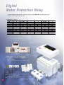
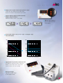
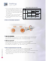
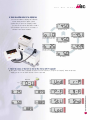
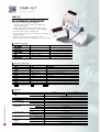
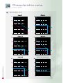
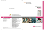
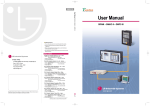
DIGITAL EMPR
Meta-MEC Series
Digital Motor Protection Relay
Digital
Motor Protection Relay
General digital type motor protection relays using MCU(Micro Controller Unit)
-Real time processing and high precision
Multiple protection
Protection
Wiring
Over current
Under current
Stsll
Lock
Phase failure
Revers phase
Asymmetry
Grount fault
�-S
DMP�
�-SZ
DMP�
�
�
�
�
�
�
�
Screw type
�
�
�
�
�
�
�
�
�-SI
DMP�
Short circuit
�
�
�
�
�
�
�
�
Install the Unit /Extension type in one body
The display part may be seperated from the body
You can check the values and the causes of the
fauit without opening the distrioution panel door
�Fig. (D-EMPR in the MCC unit)
Both screw type and tunnel type
wirings are available in a DMP-E
Type D-EMPR
Simply detach the screw terminal, you can use it by
the tunnel type reiay
Standard: IEC60947-1, IEC60947-4-1, IEC60947-5-1,
UL508, KSC4504
2
Certification & approval: CE, UL, cUL, Lloyd register,
Korea legister, KS, ISO 14001,
ISO 9001(Including proceedings)
�-T
DMP�
�-TZ
DMP�
�-T
DMP�
�
�
�
�
�
�
�
Tunnel type
�
�
�
�
�
�
�
�
�
�
�
�
�
�
�
�
M e t a - M E C
S E R I E S
Display the causes of the fault and the values
Prompt A/S by looking the LED panel which
displays the causes of the fauit and the values
3phase digital ampere-meter function
(Digital ampere-meter)
Additional ampere-meter is not needed
Motor load rate(%)
Easy to check the motor
load condition
R phase current value
S phase current value
T phase current value
Selectable either the inverse time or definite time
characteristics
Inverse time characteristics
Defiinite time characteristics
Applicable to inverter contol circuit
LG DMPR has high performance under the
harmonic noise and can be used in the
Inverter control circuit (20~200Hz)
Elegant design
High class product image
by the elegant design
3
Specifications of D-EMPR
Digital E M P R
DMP�-S
Model No.
Wiring
Panel mount
Operation time
Protection
Over current
Phase failure
Reverse phase
Asymmetry
Stall
Lock
Under current
Ground fault
Short circuit (Note2)
Alarm
Current setting range (A)
Motor capacity
220~240V
(kW)
380~440V
Time setting Definate Delay in starting
range (sec) time
Delay in operating
Inverse time
Reset
Tolerance
Current
Time
Operating power (Note3)
Voltage
Frequency
Aux. contact OL
2-SPST
AL
SPST
Insulation resistance
Surge impulse voltage(IEC1000-4-5)
Fast transient burst(IEC1000-4-4)
Environment Temperature Operation
Storage
Humidity
Display
7-Segment
Bar-Graph
Mounting type
DMP�-T
DMP06-S
DMP60-S
Screw type
DMP06-T
DMP60-T
Tunnel type
Unit or Extension(Note1)
Select either reverse time characteristics or definate time characteristics
According to the setting time
3 sec.
Within 0.1 sec.
5 sec.
5 sec.
Within 0.5 sec.
3 sec.
Within 0.05~1 sec. Selectable (0.05~1.0sec)
Within 50ms
Variable (60~110% of the setting current)
0.5~6
5~60
0.5~6
0.09~0.75
1.1~11
0.09~0.75
0.12~1.5
2.2~22
0.09~1.5
0~60sec
0~30sec
0~60sec
Manual reset
±5%
±5% (or±0.5sec)
AC 190~250V
60Hz (50Hz)
3A/250Vac Resistive load
3A/250Vac Resistive load
Over DC 500V 100㏁
1.2×50㎲ 6kV (Apply standard wave form)
2.5kV/5min
-25~70℃
-30~80℃
30~90% RH (No freezing)
3 phase current, cause of a fault
60~110% of real load current
35mm Din-rail/Panel
5~60
1.1~11
2.2~22
Note1) In extension type, the digital EMPR is calibrated with combining the display past and mainbody so, please cautious not to
combine the display part and main body with different part No.
Note2) Instantaneous short circuit protection is optional
Note3) Operational voltage of AC 110V and 50Hz is optional
4
Setting
M e t a - M E C
S E R I E S
Digital E M P R
Before operating a motor, set the D-EMPR as follows
1. C h e c k t h e o p e r a t i o n o f t h e T e s t / R e s e t b u t t o n
� Check the operation when it is tripped
1) Check the wiring method (Refer to P13~14)
2) Press the Test/Reset button and then test is
displayed on the LED and the DMPR is tripped
3) Press the Test/Reset button again and then
it is reset
Note) In order to avoid the trip fault, the push
operation of Test/Reset is not avaiable
when a motor is rotating
R phase
Digital display
Bar graph
S phase
T phase
Display button
Test/Reset button
FUNC button
Sel button
Current knob
Time knob
2. Shift the mode by pressing the FUNC key and then select the values by press the Sel key
� You can finish the setting by pressing the Sel key in the Sto mode
� To protect the operation under the motor rotating, setting is allowed only in the test mode
FUNC
Sel
Functions
Note
Inverse or definite time
characteristics
Default is inverse time
characteristics
Set the O-time
(Definite time only)
For D-time setting,
use the time knod
Reverse phasse protection
Default is ”Off”
Under current protection
Default is ”Off”Note1)
Alarm function
(With pre-alarm function)
Default is ”Off”
Ground fault and
Setting the operating time
Default is ”Off”
(Z type)
Stall function
Default is ”Off”
Lock function
Default is ”Off”
CT ratio
Default is 1:1
Phase failure
Default is ”On”
to store
Store
Push the SEL button
to store
Note2)
Note1) Set the under current value from above 350mA
Note2) Do not change the CT ratio in 60 type (Dafault is 10:1)
1) First shift to the test mode by press the ”Test/Reset”button and then set the functions
by press the ”FUNC”button
2) Each time you press the ”FUNC”button, the function mode switches from 1.CHA mode to Sto mode.
When the mode that you want to change is displayed, push the ”Sel”button to select the value you want.
After you select the value, press the ”FUNC”button to finish the settings and it displays the next mode
3) If no button is pressed in the selection mode, it remains in that mode
4) If you select the inverse time characteristics it skips the mode 2 (Definite O-time) and go to the
mode 3 (Reverse phase)
5
Setting
Digital E M P R
Alarm signal (Alert function)
5) 5. Alt is the alert setting mode. It displays the load rate
of the current setting value by the bar LED (60~110%)
- If the current is higher than the setting value, the bar
LED is swieched on and off and the AL relay(07-08) make
close and open in 1sec interval unitl the EMPR is tripped
(Pre-alarm function)
- If the 5. Alt mode is set to off, the AL relay make close
after the EMPR is tripped (Normal open contact)
6) To finish the settings you have to press the ”Sel”button
in the Sto mode
5.A Lt
On
AL(07-08) contact operation
1
0
1
0
Off
Normal
Alarm
Alert setting
value
Trip
Trip setting
value
3. Adjust the operating time by the time knod
▶ Inverse time characteristics
1) Select the inverse time in the 1. CHA mode, the default operating time is 600% of the rated current
2) The setting range of the operating time is 0~60sec. Set the time by considering the motor start time
3) When it is over the setting time, the EMPR operate in accord with the hot curve
▶ Definite time characteristics
1) Select the definite in the 1. CHA mode, it is operated by the definite time characteristics
2) D-time means the time that delays the operating time when the motor is starting
3) The setting range of the operating time is 0~60sec. Set the time by considering the motor start time
4) Set the O-time at the setting mode 2. dEF and the range is 0~30sec
4. Adjust the operating current by the current knob
1) Set the operating current based on the rated current that is discribed in the name plate.
Gennerally set the 110~115% of the real load current in the normal load condition
2) There ara 2 CT types according to the current range (0.6 / 60). When you use the external CT you can see
the real current by set the CT ratio (In 60CT type the defaut CT ration is 10:1)
3) You can easily set the current value by refer to the load rate which is displayed on the bar-graph
(Approx. 90% load rate)
6
M e t a - M E C
S E R I E S
5. Check the setting state by the display key
1) In normal condition it display the maximum
current among the three phase current
2) Each time you press the“Display”button
you can see the current and values as PIG X
3) If no button is pressed for 3~4 seconds. it
returned to the normal condition
R phase current
Set the O-time to 10sec
S phase current
(Display only in definite time)
Normal condition
T phase current
Set the D-time to 10sec
(Set the motor starting time)
5A setting
6. Check the causes of the fault by look at the display unit (7-segment)
� The causes of the fault is switched on and off for 0.5sec interval. If you press the“Display”button at this time,
display you can see the values and the causes of the fault
Overload
Turn on
ex)
Turn
on& off
Under current
Phase fail
Stall
Lock
Reverse phase
Ground fault
Short circuit
7
Dimensions
Digital E M P R
Type
Mounting dimensions
Dimensions
0.7kg
※Aux. contact wire size
:below 8[mm2]
※Torque : 0.5N
DMP�-S
DMP�-SZ
0.64kg
DMP�-S
DMP�-SZ
&
Extension
cable
Panel mounting
8
Panel cutting size
M e t a - M E C
Type
S E R I E S
Mounting dimensions
Dimensions
0.56kg
※Wire size to penetrate a CT
:below 22[mm2]
DMP�-T
DMP�-TZ
0.5kg
DMP�-T
DMP�-TZ
&
Extension
cable
Panel mounting
Panel cutting size
Note1) In extension type, the digital EMPR is calibrated with combining the display unit and mainbody
so, pleose cauyious not to combine the display unit and mainbody with different part No.
Note2)The 07-08 contacts ara the ZCT input terminal (Digital EMPR with ground fault function)
9
DMP-S/T
Digital E M P R
DMP- S/ T
Over-current/Under current/Phase failure/Asymmetry
Stall/Lock/Instantaneous short circuit protection
�Unit type or extension type is available
- Extension type:Remotely mounts the display unit
on the panel surface
�3 phase ampere meter function:Check the 3 phase
current and setting value by press the display button
�Select the inverse time or definite time
�Easy to operate:Set the most function by the operation
button and knod
�Display the causes of the fault and the values
�Alarm setting:Load ratio is displayed up to setting current
Protect function
Over current
Depend on setting time
Selectable the inverse/definite
Phase loss
Within 3seconds
Over 70% of the rate of unbalance
Phase unbalance
Within 5seconds
Over 50% of the rate of unbalance
Phase reverse
Within 0.1seconds
Function enable
Stall
Within 5seconds
Over 180% of the setting current
Lock
Within 0.5seconds
Setting 200~900% of rated current
Under current
Within 3seconds
Setting 30~70% of rated current
☞ Lock protection is operated after setting D-time in case of definite time type
Function selection
FUNC
1. CHA
2. dEF
3. r.P
4. Und
5 . A lt
6. S t l
7. Loc
8. Ct
9. P.F
Sto
☞
Sel
Inv/dEF
0~30(S)
oFF/on
oFF/30~70(%)
oFF/60~110(%)
oFF/on
oFF/200~900(%)
1~120
on/oFF
Sto
Description
Operating characteristics setting(Inverse/definite time type)
Setting the operating time(In definite type)
Phase reverse enable
Under current enable and setting
Alerting enable and setting
Stall enable
Lock enable and setting
CT ratio setting
Phase fault enable
Store
2.dEF is only displayed when dEF is selected in a 1.CHA mode
Ratings
Model
Type
10
Wiring method
Panel mount
Operating characteristics
Alerting function
Current range(A)
DMP06-�
DMP60-�
Setting time
Definite Delay(D-T)
Operating(O-T)
Inverse
Reset type
Operating voltage
Voltage
Frequency
Aux. contacts
OL
2-SPST(95~98)
AL
SPST(07-08)
Indicate
7-segment
Bar-LED arrys
Mounting
D M P � -S
Screw
D M P � -T
Tunnel
Unit or Extension
Inverse/definite type
Variable between 60 and 110%
0.5~6
5~60
0~60seconds
0~30seconds
0~60seconds
Manual reset
AC 190~250V
60Hz (50Hz)
3A/250Vac resistive load
3A/250Vac resistive load
3-phase current value, fault cause
Load ratio (60~110%)
35mm Din-rail/Panel
M e t a - M E C
Wiring method
S E R I E S
1 Phase motor
Note1)
Operational
power
External CT combination
Note1) Please turn off the reverse phase function when it is used for 1 phase motor
11
DMP-SZ/TZ
Digital E M P R
DMP-SZ/ TZ
Over-current/Under current/Phase failure/Asymmetry
Stall/Lock/Ground-fault
�Unit type or extension type is available
- Extension type:Remotely mounts the display unit
on the panel surface
�3 phase ampere meter function:Check the 3 phase
current and setting value by press the display button
�Select the inverse time or definite time
�Easy to operate:Set the most function by the operation
button and knod
�Display the causes of the fault and the values
�Ground fault protect function is added
Protect function
Over current
Phase loss
Phase unbalance
Phase reverse
Stall
Lock
Under current
G r o u n d f a u l t (Note1)
Depend on setting time
Selectable the inverse/definite
Within 3seconds
Over 70% of the rate of unbalance
Within 5seconds
Over 50% of the rate of unbalance
Within 0.1seconds
Function enable
Within 5seconds
Over 180% of the setting current
Within 0.5seconds
Setting 200~900% of rated current
Within 3seconds
Setting 30~70% of rated current
Selectable
Grounded current setting by dip s/w
0.05~1.0seconds
(100~2500mA)
☞ Lock protection is operated after setting D-time in case of definite time type
Function selection
FUNC
1. CHA
2. dEF
3. r.P
4. Und
5. g-F
6. S t l
7. Loc
8. Ct
9. P.F
Sto
☞
☞
Sel
Inv/dEF
0~30(S)
oFF/on
oFF/30~70(%)
oFF/0.05~1.0(S)
oFF/on
oFF/200~900(%)
1~120
on/oFF
Sto
Description
Operating characteristics setting(Inverse/definite time type)
Setting the operating time(In definite type)
Phase reverse enable
Under current enable and setting
Ground fault enable and setting
Stall enable
Lock enable and setting
CT ratio setting
Phase fault enable
Store
2.dEF is only displayed when dEF is selected in a 1.CHA mode
Ground fault sensitive current selection : Refer to page 15
※ 2.dEF : Refer to page 10
Ratings
Model
Type
Operating characteristics
Alerting function
Current range(A)
Setting time
Operating voltage
Aux. contacts(2a, 2b, 1a1b)
Indicate
12
Mounting
Wiring method
Panel mount
DMP06-�
DMP60-�
Definite Delay(D-T)
Operating(O-T)
Inverse
Reset type
voltage
Frequency
ZCT input (07-08)
OL, GR
2-SPST(95~98)
7-segment
Bar-LED arrays
DMP �-SZ
Screw
DMP� -TZ
Tunnel
Unit or Extension
Inverse/definite type
Variable between 60 and 110%
0.5~6
5~60
0~60seconds
0~30seconds
0~60seconds
Manual reset
AC 190~250V
60Hz (50Hz)
200mA/110mV(ZCT)[30ф, 50ф, 65ф, 80ф]
3A/250Vac resistive load
3-phase current value, fault cause
Load ratio (60~110%)
35mm Din-rail/Panel
M e t a - M E C
S E R I E S
Wiring method
External CT combination
13
Characteristics curve
Digital E M P R
Characteristics curve
Definite time characteristics
14
Ordering
M e t a - M E C
S E R I E S
Digital E M P R
DMP06 - SZ 220
Current setting range
Option
Wiring method
Operational power
06
0.5~6A
S
Screw
- Standard
220
AC220V
60
5~60A
T
Tunnel
Z Ground fault
110
AC110V
�The standard length of a extension cable is 1.5m,
2m, 4m cable is optional
�For ground fault protection, ZCT (30�,50�,65�,80�)made by
LG is optionally required
1) Detach the screw terminal
2) Select the ground fault sensitive current
Remove the 3 screws either in the line side or
the load side and pull out the bus bar.
If you remove the screw terminal, you can
use it as a tunnel type digital EMPR,
assemble it to the opposite sequence
Dip s/w
Sensitive current
(mA)
1
2
3
4
100
�
�
�
�
200
1
�
�
�
500
�
1
�
�
1000
�
�
1
�
1500
�
�
�
1
2000
�
�
1
1
2500
1
1
1
1
Note) High sensitive current(30~300mA)
is optional
ZCT( Zero-phase Sequence Current Transformer)
Ratings
ZCT,
ZCT,
ZCT,
ZCT,
Type
D30, DMP-Z
D50, DMP-Z
D65, DMP-Z
D80, DMP-Z
Diameter(A)
30
50
65
80
Ratio
200mA/100mV
Weight(kg)
0.5
0.7
0.9
1.5
Model
LZT-030
LZT-050
LZT-065
LZT-080
Dimension
Unit (m/m)
Model
A
B
LZT-030
30
25
LZT-050
50
25
LZT-065
65
LZT-080
80
C
D
E
F
G
H
ф
108 100 114
7
32
32
6
131 100 122
7
32
36
6
26
143 114 133
7
39
37
6
34
174 160 180
7
40
40
6
15
2003-09
Safety Instructions
For your safety, please read user’s manual thoroughly before operating.
Contact the nearest authorized service facility for examination, repair,
or adjustment.
Please contact qualified service technician when you need maintenance.
Do not disassemble or repair by yourself!
Any maintenance and inspection shall be performed by the personnel having
expertise concerned.
[email protected]
LG Industrial Trading (Shanghai) Co., Ltd
China
Address: Room1705-1707, 17th Floor Xinda
Commerical Building No 318, Xian Xia Road Shanahai
Tel: 86-21-6252-4291
Fax: 86-21-6278-4372
e-mail: [email protected]
Room 303, 3F
LG Industrial Systems Shanghai Office
China
Address: Room1705-1707, 17th Floor Xinda Commerical Building
No 318, Xian Xia Road Shanahai, China
Tel: 86-21-6278-4370
Fax: 86-21-6278-4301
[email protected]
LG Industrial Systems Guangzhou Office
China
Address: Room 303, 3F, Zheng Sheng Building, No 5-6, Tian He
Bei Road, Guangzhou, China
Tel: 86-20-8755-3410
Fax: 86-20-8755-3408
[email protected]
Specifications in this catalog are subject to change without notice due to
continuous product development and improvement.
DMPR 2002.10 / (02) 2003.09 Printed in Korea STAFF