1
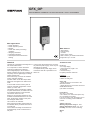
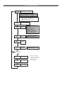
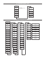
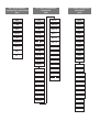
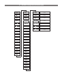
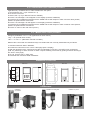
GFX_OP
PROGRAMMING TERMINAL FOR GEFLEX RANGE / GFX4 / GFXTERMO4
Main applications
•
•
•
•
Plastic extruders
Plastic injection presses
Blowers
Plastic and rubber processing
machines
• Wrapping machines
• Packaging machines
• Thermal processes with electric
heating
Main features
• Triple Display
• 6 function keys
• 14 LEDs
• Power supply 24Vdc
• Built-in memory to load/download Geflex
configuration up to 10 units
TECHNICAL DATA
PROFILE
Terminal for configuration and diagnosis of
the whole Geflex series.
It is composed of a lexan membrane
(ensuring an IP65 front protection).
Three 4-digit displays, two of which to
display variables (PV process variable, SP
set point), and a 2-digit display to identify
Geflex queried node.
Six function keys to access the software
menus and make settings.
Fourteen LEDs: six for the output status
diagnosis, and eight for the status instrument.
It comes with a built-in memory able to
save the complete configuration of each
Geflex, up to ten units.
This feature makes it particularly suitable
for plant maintenance, as Geflex units can
be configured directly on site and data
can then be stored on a PC.
Moreover, the opposite operation is also
available: download data from a PC to the
GFX_OP terminal, operate on the plant
and configure Geflex units.
Two versions are available:
back-of-board mounting: the terminal can
be installed directly on Geflex heat sink or
on a DIN rail;
front-of-board mounting: the terminal can
be fixed directly on the control board of
the plant.
In both cases the terminal does not need
any external power supply, as this is provided directly by Geflexs.
A complete 24Vdc power supply and a
connection cable kit is provided for use
with a PC.
FACEPLATE
4+4+2 digit display,
7 green segments, height 7 mm
14 red LEDs,
6 mechanical keys
Faceplate protection with lexan.
Installation
To faceplate panel.
Installed on DIN guide.
SERIAL LINE
- RS485 interface for connection to the
GEFLEX modules.
- RS232 interface for connection with PC for
WINSTRUM software.
(see Geflex accessories)
POWER SUPPLY
24V ±25%, max. 80mA
A 90...260Vac, 50...60Hz mains power supply is available as accessory.
It is not necessary when the terminal is connected to an already powered GEFLEX
module.
AMBIENT CONDITIONS
Working temperature range: 0...50°C
Storage temperature range: -20...70°C
Humidity: 20...85% Ur non condensing
WEIGHT
90g.
1 • DESCRIPTION FACEPLATE
A - Indication of active outputs - Display state Out1,...,Out6
B - Indication of status instrument
RUN, ERR repetition of state of LEDs on Geflex
TUNE on if selftuning or autotuning is active
MAN on and control in manual state
REM on if remote set point is enabled
SP2 on if setpoint 2 is selected
DIG on if digital input is active
AL on if at least one alarm is active
N
C - PV Display: indication variable / parameter code
D - SV Display: indication variable value
A
C
D
E
B
F
G
H
L
I
M
E - Display of queried node
Meaning of flashing decimal points on ID display:
Both decimal points flash = serial dialog running
Only "ones" point flashes = data transfer to Geflex after "Load"
command
Only "tens" point flashes = first data read from Geflex at first
selection
Both decimal points off = serial communication absent (due to lack of
connection or incorrect ID address). In this case, the PV and SV
values are replaced by four segments “ - - - - “
F - “Lower” and “Raise” keys
Press to increment (decrement) any numerical parameter ••
Increment (decrement) speed is proportional to time key stays
pressed oo The operation is not cyclic: once the maximum (minimum)
value of a field is reached, the value will not change even if the key
remains pressed
G - “Function” key
Gives access to the various configuration phases
Confirms change of set parameters and browses next or previous
parameter (if Auto/Man key is pressed)
H - “Load” button reads a configuration (loads configuration of GFX-OP
in GEFLEX) / Operator button 1
I - “Store” button saves configuration / Operator button 2
L - Configurable button / Operator button 3
M - Geflex Serial Cable
N - Winstrum Serial Cable
2 • OPERATING NOTES
N..B.: the GFX_OP terminal becomes the master when connected to Geflexes, and becomes the slave when connected to the Winstrum.
Recognition is at switch-on if it is connected to one of the two serial cables.
At power-up, the GFX_OP terminal turns on and tries to connect with the Geflex at the displayed ID address.
In the absence of a connection to display PV and SV, the indication “ - - - - " appears.
The parameters that can be displayed and/or set (Cod, BAu, PAr, Pro, but) reside in the terminal's EEPROM
memory.
When the connection is active (both decimal points on the ID display flashing), the data is automatically updated
with those contained in the connected Geflex.
Set the ID field with the "up" and "down" keys; if this corresponds to a Geflex in line, the connection will activate
with display of the process variable and setpoint, together with updating of the state by means of the faceplate
LEDs.
N.B.: the “LoAd” and “Stor” or “Operator button” functions are active only in level 1 display when process variable
“PV” and active setpoint “SP” are displayed and when the “bOP” parameter equals 0.
Description of "LoAd" function (GFX_OP -----> Geflex)
It activates when the “L” key is pressed, and asks confirmation of the configuration number, one of the 10 possible
numbers (codes 0-9) that you want to load in the Geflex; code 10 = exit.
The display will show the message "LoAd" with the proposed number corresponding to the least significant digit in
the ID field: for example, if the ID is 15, the number of the proposed configuration is 5.
Press key "F" to proceed.
During updating of the data in Geflex, only the "ones" point will flash on the ID display.
In master mode (connected to Geflex), correspondence of the software version is checked when the message
“LoAd” appears and a saved configuration is selected. If the version differs from that in the Geflex in dialog, the
configuration number will flash; if it is the same, the number will not flash.
The configuration number also flashes if it has never been used to save data.
In slave mode (connected to Winstrum), the configuration number does not flash.
Description of "Stor" function (Geflex -----> GFX_OP)
It activates when the “S” key is pressed, and asks confirmation of the configuration number, one of the 10 possible
numbers (codes 0-9) that you want to save the configuration; code 10 = exit.
The display will show the message "Stor" with the proposed number corresponding to the least significant digit in
the ID field: for example, if the ID is 23, the number of the proposed configuration is 3.
Press key "F" to proceed.
Description of “Operator button” functions
These are present only with GFX4 or GFXTERMO4 and are active with the “bOP” parameter other than 0. They
deactivate the “LoAD” and “Stor” functions of the configurations and display the state of keys “L” and “S” on the
supervisor terminals or PLCs connected to serial port 2 of the GFX4. In “4 GEFLEX simulation” mode (GFX4 dip
switch 7 ON), they are active only if you display the first zone of the GFX4 or GFXTERMO4 in level 1 display condition with PV + Set Point.
bOP = 1: “Operator buttons with momentary action.” Pressing the “L” key forces to 1 bit 0 of the variable for the
MODBUS 685 address in the first zone; pressing the “S” key forces bit 1 to 1. Release the key to force
to 0 the bit for the previously pressed key.
bOP = 2: Operator buttons with alternate action.” Pressing the “L” key forces to 1 bit 0 of the variable for the
MODBUS 685 address in the first zone; pressing the “S” key forces bit 1 to 1. Releasing the key does
not change bit state; press the key again to force to 0 the bit for the previously pressed key.
The “FbOP” (Operator buttons) parameter can be used to prevent “rebounds” when keys are pressed. The parameter is settable in tenths of a second, which is the minimum pressing time of the key before the state of the corresponding bit is forced. By setting the “bUt” parameter to 10 or 11 you get the same functions with the “Configurable button,” which forces to 1 bit 2 of the variable for the MODBUS 685 address in the first zone.
3 • AUTOMATIC SCROLLING” FUNCTION”
1. Description
If the function is on (parameter OP.t = 1), the operator terminal automatically runs “scrolling” of the connected
Geflexes from a set first ID code “FST” to a set last code “LST”.
When the “LST” code is reached, the scan restarts.
The initial reading of configuration parameters takes place with each new ID code, followed by continuous reading
of state variables (PV, SSP, POWER, main function state).
A single Geflex is monitored for a settable time “CYC.”
If a Geflex (ID) is not present, or does not communicate in Modbus, switching to the next one is almost immediate
(after a brief wait needed to confirm non-communication state).
During scrolling, you can manually switch to another ID code at any time with the Raise and Lower keys.
Scrolling resumes after time CYC from the newly set code.
Press any key to suspend scrolling. In this way, you can display or change the configuration of a single Geflex, run
LOAD and SAVE procedures, or activate enabled functions with the configurable key.
After time CYC has lapsed without any key having been activated, the cycle resumes from the current ID code.
4 • PROGRAMMING and MENU CONFIGURATION
LEVEL 1 MENU
P.V.
Process variable
spa
Active Setpoint
- sp
Local Setpoint
SP.1
Setpoint 1
SP.2
Setpoint 2
In2
Auxiliary input value
I.tA1
Ammeter input value
I.tA2
Ammeter input value
I.tA3
Ammeter input value
I.tU1
Voltmetric input value
I.tU2
Voltmetric input value
I.tU3
Voltmetric input value
al.1
Alarm point 1 (scale points)
al.2
Alarm point 2 (scale points)
al.3
Alarm point 3 (scale points)
al.4
Alarm point 4 (scale points)
a.xb1
Heater break alarm point
(scale points of ammeter input)
a.xb2
Heater break alarm point
(scale points of ammeter input)
a.xb3
Heater break alarm point
(scale points of ammeter input)
Control output value (+Heat / -Cool)
0V.P
(parameter settable only if Geflex is in
manual mode [MAN LED on])
The automatic return to PV/SV display is
disabled when “manual valve control” is
active
INFO
Information display
I.tAP
Peak ammeter input during phase
softstart ramp for zone
FrEq
Voltage frequency in tenths of Herz
for zone
I.U21
Linked voltage V21
I.U32
Linked voltage V32
CFG
Custom menu
SEr
Serial communication
InP
Input settings
I.U13
Linked voltage V13
Out
Output settings
(oS.F
Power factor in hundredths for zone
PAS
Password
Ld.P
Power on load for zone
Ld.P.t
Power on 3-phase load
Ld.I
Impedance on load for zone
Ld.I.t
NO
Voltage on load for zone
Ld.U.t
Voltage on 3-phase load
Pro
Protection code
Hrd
Hardware configuration
Lin
Input linearization
Ld.A
Current on load for zone
Ld.A.t
Current on 3-phase load
xb.tr
HB alarm setpoint based on power
on load for zone
U.CA
Release the F key
to select the
displayed menu.
Press the F key to
access the
parameters.
PAS = 99
Impedance on 3-phase load
Ld.U
Keep the F key
pressed to scroll
the menus.
User calibration
Keep the F key
pressed to exit any
menu.
Keep F + Auto/Man
keys pressed for 2
sec. on any menu
to go immediately
to level 1 display
You can immediately go to the
previous parameter
by pressing the
Auto/Man + F keys
on any menu.
If Inc, Dec, F keys are not pressed within 15 sec,
display returns automatically to P.V. value
N.B.: Once a particular configuration is entered, all unnecessary parameters are no longer displayed
The displayed parameters depend on the firmware release of the selected Geflex..
For the list and meaning of parameters shown in different menus, please refer to the Geflex user manual.
4.1 • Protection code (Pro)
Pro
Protection code
Pro
0
1
2
Display
SP, In.tA, In.tU, alarms, OuP, INFO
SP, In.tA, In.tU, alarms, OuP, INFO
SP, In.tA, In.tU, OuP, INFO
+4
+8
+16
+64
+128
to disable InP, Out
to disable CFG, Ser
to disable SW “power-up / power-down” from key
to disable manual power modification
access to all parameters in unconditional mode
(standard + valve + hot run ecc...)
U.0P
0
Modification
SP, alarms
SP
Display software version of
GFX-OP terminal
but
Configurable
function key
b0P
Function keys
“L” and “S”
Fb0P
Operator
buttons filter
(0.0...1.5sec)
OP.t
Automatic
scrolling option
0
1
2
3
4
5
6
8
9
10
11
no function (key disabled)
MAN/AUTO
LOC/REM
HOLD
Alarms memory reset
SP1/SP2 selection
Software On/Off
START/STOP Selftuning
START/STOP Autotuning
Operator buttons 3 “momentary”
Operator buttons 3 “alternate”
0
1
2
“Load” and “Stor” configurations
Operator buttons “momentary”
Operator buttons “alternate”
0
1
Manual scrolling
Automatic scrolling
OP.t
1
FSt
First ID code
(0...99)
Note: the “Fst” and “Lst”
parameters are used to set
both the “code” automatic
scrolling and manual
LSt
Last ID code
(0...99)
(y(
Display delay
(10...30 sec)
browsing ranges
4.2 • Information registers (InFo)
InFo
d.1.d
= 192 for Geflex
= 198 for GFX4 / GFXTERMO4
= 212 for GFX4-IR
(.xd
upd
(.xd1
err
UPd.F
er.2
(od.F
FUSE
bAu.F
4.3 • Controller configuration parameters (CFG)
A.rs
PF.t
Xd.5
Enable trigger mode
for zone
h.pb
ffd
SP.s
PS.t. M
Duration of phase softstart ram
for zone
h.it
sof
So.P
PS.tA
Max. peak current limit during
phase softstart ram
for zone
h.dt
Xy.i
-at-
Fv.tA
Max. rms current limit at speed
for zone
h.p.x
Xy.2
t lo
bF.(y
Min. number of cycles of BF mode
for zone
h.p.l
Xy.3
t - xi
dL.t
Delay triggering (first trigger only)
for zone
(.ME
Xy.4
t.on
dL.oF
Min. non-conduction time to
reactivate delay triggering
for zone
c.sp
xb.t
t.off
xb.P
Percent HB alarm setpoint based
on power on load
for zone
c.pb
lb.t
-db-
c.it
lb.p
riF
c.dt
fa.p
(or
c.p.x
g.sp
PS.oF
c.p.l
g.s2
PS.x1
rst
b.st
P.rs
b.Pf
-
-
S.tv
-
(FG
4.4 • Serial interface
configuration parameters
(Ser)
4.5 • Input configuration
parameters
(InP)
4.6 • Output configuration
parameters
(Out)
Ser
InP
x.tA2
Out
(od
sp.r
G.TA3
a1.r
bav
typ.
x.tA3
a2.r
bav.2
tP.2
o.tA1
a3.r
par
flt
o.tA2
a4.r
par.2
fld
o.tA3
a1.t
s.in
dp.s
x.tU1
a2.t
s.0v
lo.s
x.tU2
a3.t
S.L1
xi.s
x.tU3
a4.t
ofs.
o.tU1
xb.f
ft.ta
o.tU2
rl.1
ft.tU
o.tU3
rl.2
LS.2
lo.l
rl.3
xS.2
xi.l
rl.4
FLt.2
rl.5
dP.2
rl.6
oFS.2
(t.1
x.tA1
(t.2
G.TA2
rel
RAP
at.ty
4.7 • Hardware configuration parameters (Hrd)
xrd
ovt.1
xd.6
Enable feedback mode
for zone
hd.1
ovt.2
(or.U
Max. voltage feedback correction
for zone
(tr
ovt.3
(or.I
Max. current feedback correction
for zone
al.n
ovt.4
(or.P
Max. power feedback correction
for zone
dig.
ovt.5
riF.U
Voltage feedback reference
for zone
dig.2
ovt.6
riF.I
Current feedback reference
for zone
ld.St
ovt.7
riF.P
Power feedback reference
for zone
ld.2
ovt.8
ld.3
ovt.9
ld.4
ovt.10
ld.5
SPU
ld.6
hd.2
ld.7
dG.t
ld.8
dG.F
AI.2
dG.P
xOT
hd.3
I.xEU
hd.4
I.xEt
P.0n.t
0FF.t
4.8 • Custom linearization for PV
main input PV (Lin)
4.9 • User calibration
Lin
U.(A
s.00
= 1 potentiometer input
(GEFLEX)
......
s.32
s.33
s.34
s.35
=1
=2
=3
=4
+16
+32
+64
20mA In.1 zone 1 (TYP = 46)
60mV In.1 zone 1 (TYP = 48)
PT100 In.1 zone 1 (TYP = 50)
In.TA zone 1
for zone 2
for zone 3
for zone 4
(GFX4)
4.10 • Potentiometer input calibration procedure
Applicable only on Multifunction or Valve models with "P0" option.
1. Set parameter AI.2 = 4 (for valves tP.2 = 5)
2. Go to the U.CA menu
3. Select code 1 (0 if you DO NOT want to calibrate)
4. Press F: the message C.LO will appear on the display (minimum calibration)
5. Press the UP or DOWN keys assigned to the OPEN and CLOSE outputs to reach minimum valve position,
position the potentiometer at minimum
6. Press F: the message C.HI will appear on the display (maximum calibration)
7. Press the UP or DOWN keys assigned to the OPEN and CLOSE outputs to reach maximum valve position,
position the potentiometer at maximum
8. Press F to return to the main menu (level 1)
4.11 • Manual valve control procedure
Configure parameters: “hd.1 = +16” (open/close in valve control)
“At.ty = +8” (manual valve control)
“diG = 1” or “but = 1” (Man/Auto controller condition)
Manual valve control with the raise/lower keys is activated and then correctly deactivated only as follows:
1. Activate instrument state in MANUAL.
2. Position the instrument on the "Out P" video page (level 1 display).
3. With the raise/lower keys, open/close the valve as indicated by LED Out 1 and LED Out 6, respectively.
(N.B.: any switching to "Auto" and then to "Man" requires resetting of the state by quitting and then returning to
the "Out P" video page).
4. To end, quit the "Out P" video page.
5. Deactivate the instrument state in MANUAL.
DIMENSIONS and CUT-OUT
GFX-OP-D
GFX-OP-P
44.5
10
55
91.5
34.0
ø 3.5
92
25.5
ø 3.5
ø 22.0
5.0
44.0
33.0
CONNECTIONS
Installation
on heatsink
Installation on DIN guide
Installtion on panel
ORDER CODE
Programming terminal for Geflex (installation on DIN guide or on heatsink), complete with connection
cable to Geflex (L=0,2m)
Note: see cable section for other cable lengths
GFX-OP-D
Programming terminal for Geflex (installation on faceplate)
Note: see cable section for connection cable
GFX-OP-P
Kit consists of:
power supply, connection cable PC <--> GFX-OP-D (L=1,5 m),
power adapter for the Geflex
GFX-OP-K
ACCESSORIES
Connection cable for GFX-OP <-> Geflex or for Geflex Slave <-> Geflex Slave
CV-1
complete with connectors, length 1m
Connection cable for GFX-OP <-> Geflex or for Geflex Slave <-> Geflex Slave
CV-2
ccomplete with connectors, length 2,5m
Connection cable for GFX-OP <-> Geflex or for Geflex Slave <-> Geflex Slave
complete with connectors, length 5m
CV-5
Stabilized power supply (24 Vdc,12W) complete with power adapter for Geflex
PWS24
3-terminal connector (J2) for Geflex Slave to an output
CSIG-3
7-terminal connector (J1) for Geflex Master/Slave inputs/power supply
CSIG-7
8-terminal connector (J2) for 3-output Geflex Master/Slave
CSIG-8
• WARNING
!
WARNING: this symbol indicates danger.
Read the following warnings before installing, connecting or using the device:
• follow instructions precisely when connecting the device.
• the instrument must be used exclusively with the Geflex product as specified on the connection diagram.
• the device has no ON/OFF switch: it switches on immediately when power is turned on.
• if the device is used in applications where there is risk of injury to persons and/or damage to machines or materials, it MUST
be used with auxiliary alarm units. You should be able to check the correct operation of such units during normal operation of
the device.
• before using the device, the user must check that all device parameters are correctly set in order to avoid injury to persons
and/or damage to property.
• the device must NOT be used in inflammable or explosive environments. It may be connected to units operating in such env
ronments only by means of suitable interfaces in conformity to local safety regulations.
• the device contains components that are sensitive to static electrical discharges. Therefore, take appropriate precautions when
handling electronic circuit boards in order to prevent permanent damage to these components.
Read the warnings in the instruction manual regarding installation conditions for the Geflex device.
GEFRAN spa will not be held liable for any injury to persons and/or damage to property deriving from tampering, from
any incorrect or erroneous use, or from any use not conforming to the device specifications.
CE MARKING: EMC conformity (electromagnetic compatibility) with EEC Directive EMC 2004/108/CE with reference to the
generic Standard EN61000-6-2 (immunity in industrial environments) and EN61000-6-3 (emission in residential environments).
BT (low voltage) conformity respecting the Directive EN 2006/95/CE.
MAINTENANCE: Repairs must be done only by trained and specialized personnel.
Cut power to the device before accessing internal parts. Do not clean the case with hydrocarbon-based solvents (Petrol,
Trichlorethylene, etc.). Use of these solvents can reduce the mechanical reliability of the device. Use a cloth dampened in ethyl
alcohol or water to clean the external plastic case.
SERVICE: GEFRAN has a service department. The warranty excludes defects caused by any use not conforming to these
instructions.
GEFRAN spa via Sebina, 74 - 25050 Provaglio d’Iseo (BS)
Tel. 03098881 - fax 0309839063 - Internet:
http://www.gefran.com
DTS_GFX-OP_0709_ENG


![Régulateurs (PDF/1,26Mo) [F]](http://vs1.manualzilla.com/store/data/006367628_1-d11067c6e30136a71de027b5803c5ae5-150x150.png)