1
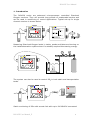
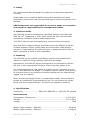
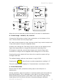
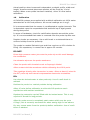
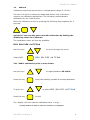
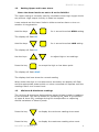
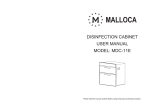
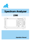
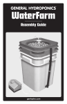
DO102X* Series Dissolved O2 Monitor/Controller User Manual * Note: Software functionality covers 1020-1022 & 1024-1026 variants http://www.ohdesigns.co.uk [email protected] O&H Designs 35 Barton Rd Barlestone Warwickshire CV13 0ER England Tel 01455 290 620 This document is the property of O&H Designs and may not be reproduced nor stored on any data processing system, either in part or whole, without the written permission of O&H Designs. DO102X User Manual Contents PG Introduction 3 Safety 4 Electrical Safety 4 Mounting 4 Specifications 4 Abbreviations 5 Initial Usage DO1020 5 Initial Usage DO1021,22,24-26 6 Probe Placement 6 Calibration 7 Method 8 Setting Upper & Lower Alarms 9 Minimum & Maximum readings 9 Setting Atmospheric Pressure 10 Setting Salinity 11 Platinum Resistance Probe 12 Probe Temperature Coefficient 12 Service & Warranty 13 DO102X User Manual_E 2 DO102X User Manual 1. Introduction The DO102X series are advanced microprocessor controlled Dissolved Oxygen monitors. They will provide long periods of unattended service and can be used in monitoring or control applications. Typical set-up for single channel versions is shown below. Measuring Dissolved Oxygen levels in tanks, ponds and lakes and turning on the installed aeration system when it’s actually required thus saving energy. The system can also be used to control DO2 in both static and transportation tanks. Static monitoring of DO2 with remote link with up to 24 DO102X connected. DO102X User Manual_E 3 DO102X User Manual 2. Safety The manufacturer has designed this product to be safe when operated correctly. Please take care to read any safety instructions as these have been designed to protect the user from personal injury and the equipment from damage. O&H Designs are not responsible for errors in usage or connection and accept no responsibility for consequential losses. 3. Electrical Safety The DO102X should be installed by a qualified electrician familiar with IEEE ed. 18th regulations or VDE. Users should be fully trained in safe operational conditions of mains based equipment. 12/24VDC versions can be installed with minimal electrical training. Note that all IP integrity ratings quoted are when the DO102X units are screwed together and all mating seals are compressed. O&H Designs accepts no responsibility for personal injury or equipment failure due to water ingress as a result of poor installation. 4. Mounting The DO102X can be used as a standalone system and installed both indoors or outdoors using customer preferred mountings. Alternatively, the DO102X series is designed to be mounted to a 65mm OD pole or with appropriate fixings to a wall using the ‘option B’ kit. For remote applications, the ‘option A’ system can be connected to a P.C up to 2 kms distance via RS485. The display & power switch can therefore be mounted near to the probe and remote readings can be obtained and logged onto a computer. When monitoring Oxygen levels in transportation tanks, ensure that the probes are continually immersed during use. Do not position the probe direct over the Oxygen diffusers. The same rule applies to aerators. 5. Specifications Conformity.......................... EN61010, EN61326-1, 97/23/EC CE marked Environmental Temperature (Electronics)................................................. -10°to 40°C Storage.......................................................................... -20° to 50°C Sealing..................................................................................... IP65 Weight (approximate)...DO102X.............................................. 450gms Weight (approximate)...DO1024............................................. 1100gms DO102X User Manual_E 4 DO102X User Manual Dimensions DO1020 Width................................................................................... 100 mm Height.................................................................................... 60mm Depth................................................................................... 100mm Dimensions DO1024 Width................................................................................... 213 mm Height.................................................................................. 119 mm Depth.................................................................................. 185 mm Power supply Mains (factory set).......................................................... 110/230 VAC Power consumption................................................................. 2 watts Low voltage option (factory set).......................................... 12-24 VDC Battery Versions NimH internal battery........................................................... 7.2VDC Consumption....................................................................... 1.4 watts Battery life at 20°C .................................................................7 hours Measurement parameters Probe type..................................................................Sealed Galvanic Probe lead length (max).............................................................. 25m Probe operating temperature range ..................................... 0° to 40°C DO2 range ....................................................................... 0 to 40mg/l DO2accuracy (instrument minus probe)........................ 3% rdg ±0.1mg/l DO2display resolution ............................................................. 0.1mg/l Maximum Probe Depth........................................................... 2.5 mtrs 6. Abbreviations Note: Abbreviations are the same in singular or plural. DO2 AC RTD °C Kms gms mm/Hg Dissolved Oxygen Alternating Current Resistive Temperature Device Degrees Celsius Kilometers grammes millimeters of mercury LED DC mg/l P.C IP KCL mb LightEmtting Diode Direct Current milligrams per litre Personal Computer Ingress Protection Potassium Chloride millibar 7. Initial Usage - D01020 When connecting the DO1020 to the power source, observe the input voltage setting for either 110VAC, 230VAC or 12-24VDC. Observe the fuse rating for the unit of T500mA 20mm size 3. If supplied, connect the power switch or O2 control valve to the 5 pin connector 1 on the side of the DO1020. Connect the DO2 probe to the 6 way connectors 2 on the side of the 5 DO1020. Connection is only fitted with option ‘A’ RS485. Remove the cover from the power switch and connect the mains device to the relevant output via the terminal blocks 4 High or Low. DO102X User Manual_E 5 DO102X User Manual 5 2 1 3 4 Fuses T10A 4 When the unit is powered up allow at least 5 minutes for stabilisation. 8. Initial Usage - DO1021, 22, 24 & 26 Connect the DO2 probes to the 6 way connectors on the bottom of the unit. Ensure these are only finger tight. If a valve control system is used, connect to the 8 way control socket and 2 way valve power using the supplied cables. If fitted, fuse ratings are T2A 20mm size for fuses on the display boxes. Cigar style plugs have an integral 8A automotive cartridge fuse. If charging is required, connect the charger port via the Cigar style connector or charge via the supplied mains charger for 12-14 hours. Pressing the power switch will turn the unit on and the system will go through a self test. The default display units are now shown in mg/l of DO2. Pressing the key will give a probe temperature reading in °C This will remain on the display for 5 seconds then revert back to DO2 9. Probe Placement Ensure that the clear protective sealing cap is removed prior to deployment. During operation, place the probe in a vertical position with the probe tip facing downwards. This is indicated on the side of the Probe housing. When positioning the probe in the water to be monitored. Take care to locate away from the direct influence of aerators/Oxygen diffusers. DO102X User Manual_E 6 DO102X User Manual Actual position when immersed is dependant on depth profile, width and length, therefore actual placement postion will be found by ‘in-situ’ testing. When a new probe has been installed, allow 30 mins before calibration. 10. Calibration All DO102X systems are supplied with a default calibration at 100% water saturated air at 1013mb pressure. All normal readings are in mg/l. It is recommended that the sensor is recalibrated at regular intervals. This is dependant upon the suspended solids and build up of algal growth during that period. In areas of hardwater, check for calcification deposits around the probe tip. It’s recommended that water is removed from the probe tip after use. Regular checks are necessary. Use a soft brush or moistened tissue to remove buildup from the probe tip. The probe is a sealed Galvanic type and thus requires no KCL solution for filling. Life expectancy in normal use is approx 30 months. DO NOT: Direct high-pressure water jets onto the probe tip as this could damage the membrane. Use abrasive wipes on the probe membrane. Clean the probe with chemicals such as Isopropyl Alcohol. Allow contact with the membrane whilst calibrating the 100% point. Take readings directly after immersion in water. Allow at least 10 mins for the DO2 probe tip and internal compensation electronics to stabilise. DO: Use clean de-ionised water to clean probe tip. Use of a soft brush is advised. Position the probe in a vertical position during calibration. Allow 10 mins before calibration to allow the DO2 probe to reach equilibrium with ambient conditions. Replace the protective cap half filled with de-ionised water. This is only required if stored for long periods. Allow for probe errors in completely static water which may be up to 0.5mg/l, this is normally accounted for when setting high or low alarms. Dry any excess water from the probe tip before calibration. Use of a soft tissue is advised. DO102X User Manual_E 7 DO102X User Manual 11. Method Calibration should be carried out in a temperature range of 15-25°C The zero 0% point is extremely stable and factory set, it therefore requires no calibration adjustment. The following method details calibration for the *100% point. Enter the calibration menu by pressing the following keys together for 3 seconds: Quick Cal: You can also get to the DO2 calibration by holding the middle key down for 5 seconds The calibration menu will now be available: DO2 SAL PrES rtd TC End Use the keys Select DO2 to scroll through the menu DO2 SAL PrES rtd TC End The *100% calibration point is now shown. Use the keys Press the key to adjust between 95-105% when the reading is stable to accept calibration to select DO2 SAL PrES rtd TC End To quit, use Press the key to quit The display will now read the calibrated value in mg/l. * Usually calibrate at 105% to allow for localised O2 consumption DO102X User Manual_E 8 DO102X User Manual 12. Setting Upper and Lower alarm Note: the alarm levels are set to 0 on the DO1021 The upper setting is normally used for circulators when high oxygen levels are present. High output circuitry is fitted on request. Lower outputs set the lower limits to either sound an alarm or turn on aeration or oxygenation. Hold the keys for 1 second to select HIGH setting The display will flash HI Hold the keys for 1 second to select LOW setting The display will flash LO Use the keys Press the key to adjust high or low settings. to accept the high or low alarm point. The display will flash dOnE The display shall now show the normal reading When either the High or Low alarms are exceeded, the display will flash and the appropriate power switch or valve connected will operate until the readings return to a normal level. 13. Minimum & Maximum readings The minimun & maximum feature allows upper & lower trends in readings to be recorded. This can be usefull for collecting DO2 data. E.g collection of upper & lower DO2 readings during fish transportaion or capturing diurnal variations in lakes & ponds. Press the key to display the minimum reading since reset. Press the key to display the maximum reading since reset. DO102X User Manual_E 9 DO102X User Manual To reset, press to High & Low will now be reset. The display will flash rSt 14. Setting Atmospheric Pressure If large swings in atmospheric pressure occur due to either altitude or weather variations, readings can be corrected for maximum accuracy. Table 1 (pg11) illustrates the relative corrections that can be applied. Enter the calibration menu by pressing the following keys together for 3 seconds: The calibration menu will now be available: DO2 SAL PrES rtd TC End Use the keys Select PrES to scroll through the menu DO2 SAL PrES rtd TC End The display will show the default of 760 mm/Hg Use the keys Press the key to adjust if required to accept the pressure reading The display will flash dOnE Use the keys Press the key DO102X User Manual_E to select End to quit to normal reading 10 DO102X User Manual The effects of adjustment of pressure are shown below. The DO102X will apply the relevant correction factors. Table 1 (m)height 0 100 200 300 400 500 15. Pressure (mmHg) 760 750 741 732 723 714 Factor 1 1.01 1.03 1.04 1.05 1.06 Setting Salinity If the instrument is usaed in brackish or seawater then a salinity correction factor can be applied to obtain maximum accuracy. Table 2 (pg12) illustrates the relative corrections that can be applied Enter the calibration menu by pressing the following keys together for 3 seconds: The calibration menu will now be available DO2 SAL PrES rtd TC End Use the keys Select SaL to scroll through the menu. DO2 SAL PrES rtd TC End The display will show the default of 0 parts per thousand(ppt) Use the keys Press the key to adjust if required. to accept the salinity reading. The display will flash dOnE DO102X User Manual_E 11 DO102X User Manual Use the keys to select End. Press the key to quit to normal reading The table below shows the effects of salinity on the readings and the factor the DO102X will appply. Table 2 Salinity ppt 0 5 10 15 20 25 30 35 16. Factor 1 0.97 0.94 0.91 0.88 0.85 0.83 0.8 Platinum Resistance probe The platinum resistance probe (RTD) provides an accurate temperature reading used for correcting for DO2 probe variations. This is shown as rtd in the calibration menu. DO2 SAL PrES rtd TC End This reading is normally factory calibrated and should not require recalibration during normal service life of the probe. Contact O&H Designs for details of re-calibration Pressing the key will give a probe temperature reading in °C This will remain on the display for 5 seconds then revert back to DO2 17. Probe Temperature Coefficent This is shown as TC in the calibration menu. DO2 SAL PrES rtd TC End Do not adjust this value as the probe will display incorrect readings at differing temperatures. Defaults values are typically -1.6. DO102X User Manual_E 12 DO102X User Manual The reading is factory calibrated and should not require re-calibration during normal service life of the probe. Contact O&H Designs for details of re-calibration 18. Service & Warranty For more information on the DO102X, contact us directly or an approved agent. O&H Guarantees the unit to be free of defects for a period of 12 months from date of manufacture. This does not cover damage to the probe tip caused by unreasonable use. This warranty excludes incidental or consequential damages arising from the use of this product O&H Designs provides a service capability for their products. Replacement probes and other spare parts are available direct. O&H Designs also offers a recalibration service for all environmental parameters. This can be on any interval as required by the customer. 2011 O&H Designs http://www.ohdesigns.co.uk [email protected] DO102X User Manual_E O&H Designs 35 Barton Rd Barlestone Warwickshire CV13 0ER England Tel 01455 290 620 13